Embed Size (px)
Citation preview

LUND UNIVERSITY
PO Box 117221 00 Lund+46 46-222 00 00
Effect of water-cement ratio, air content and age on the risk of frost damage ofconcrete : some experimental studies
Fagerlund, Göran
2012
Link to publication
Citation for published version (APA):Fagerlund, G. (2012). Effect of water-cement ratio, air content and age on the risk of frost damage of concrete :some experimental studies. (Report TVBM; Vol. 3163). Division of Building Materials, LTH, Lund University.
Total number of authors:1
General rightsUnless other specific re-use rights are stated the following general rights apply:Copyright and moral rights for the publications made accessible in the public portal are retained by the authorsand/or other copyright owners and it is a condition of accessing publications that users recognise and abide by thelegal requirements associated with these rights. • Users may download and print one copy of any publication from the public portal for the purpose of private studyor research. • You may not further distribute the material or use it for any profit-making activity or commercial gain • You may freely distribute the URL identifying the publication in the public portal
Read more about Creative commons licenses: https://creativecommons.org/licenses/Take down policyIf you believe that this document breaches copyright please contact us providing details, and we will removeaccess to the work immediately and investigate your claim.

LUND INSTITUTE OF TECHNOLOGY LUND UNIVERSITY ___________________________________________________________________
Division of Building Materials
Effect of water-cement ratio,
air content and age on the risk of frost damage of concrete Some experimental studies Göran Fagerlund
Report TVBM-3163 Lund 2012 _____________________________________________________________________

ISRN LUTVDG/TVBM--12/3163--SE(1-96)
ISSN 0348-7911 TVBM
Lund Institute of Technology Telephone: 46-46-2227415
Division of Building Materials Telefax: 46-46-2224427
Box 118 www.byggnadsmaterial.lth.se
SE-221 00 Lund, Sweden

1
SUMMARY The effect of water-cement ratio, air content and degree of hydration on the critical moisture content with regard to freeze-thaw, and on the capillary water uptake was studied. Nine different (micro-) concrete mixes were used in the investigation. 3 concretes were non-air-entrained, 6 were air-entrained. 3 different water-cement ratios were included with target values 0,40, 0,60 and 0,70. Real values of air content and w/c-ratio are shown in the table below. Concrete number w/c Air content of hardened concrete (%)
Non-air-entrained Air-entrained
11 0,42 2,8 -
21 0,43 - 5,4
31 0,43 - 6,4
12 0,64 6,2 -
22 0,64 - 10,3
32 0,61 - 17,8
13 0,70 6,3 -
23 0,73 - 8,9
33 0,74 - 11,4
The concretes were pre-cured for 5, 12, 26 or 89 days. The pre-curing procedure is described in Figures 2, 3, 4. Directly after terminated pre-curing the specimens were subject to the following measurements:
1. Determination of degree of hydration. 2. Determination of porosity, density, and air content. 3. Determination of the critical moisture content. 4. Determination of short-term and “long-term” capillary water uptake.
By combination of the critical moisture content and the capillary water uptake curve the risk of frost damage, and a “potential service life” was evaluated. Concrete properties (Chapter 3) Degree of hydration Degree of hydration was determined by ignition at +1000°C of pre-dried specimens. Determinations were made both before freeze-thaw and after terminated freeze-thaw. The hydration curves are shown in Figure 5. The spread in results for the different mixes with the same w/c-ratio is small. As expected, the final degree of hydration after 89 days curing depends on the w/c-ratio. It is lowest for w/c≈0,40 (66%) and highest for w/c≈0,70 (78%).
Early hydration at 5 days was about the same for all w/c-ratios (50%). For the concrete with exceptionally high air content (number 32) hydration was strongly retarded, probably an effect of the high amount of air-entraining admixture. The degree of hydration was the same at determination after terminated as before freeze-thaw. This shows that no significant hydration took place during freeze-thaw. All results are shown in APPENDIX 2, Table A2.1.

2
Density, porosity and air content The porosity and bulk density of each concrete type and age was determined on the same type of specimens as used for freeze-thaw. 4 specimens were used for each concrete and age. The mean value is supposed to be representative for all freeze-thaw and water absorption specimens. The determination was made immediately before freeze-thaw and before capillary water uptake. For some concretes the values were also determined after terminated freeze-thaw. The difference between pre-freezing and post-freezing values was none or very small. Bulk density was calculated from dry weight (drying at +105°C) and specimen volume. The volume was calculated from the difference in weight of specimen weighed in air and immersed in water. The density values are considered to be correct since the only major source of error, drying at +105°C, is expected to be complete due to the long drying time and small specimens. Bulk densities for all concretes are given in APPENDIX 3, Table A3.1. Porosity was intended to be calculated from the difference in weight of saturated and dry specimens. For some concrete series, water saturation was insufficient, however, which gave too small calculated porosity. The real (“true”) porosity was therefore calculated by Eq. (9) in which the true density is used. This was calculated from the mix proportions and the degree of hydration using Eq. (10). True porosities for all concretes are given in APPENDIX 3, Table A3.5. The true air content was calculated as the difference between the true porosity and the sum of capillary and gel porosity. The latter was calculated by Eq. (11). The air content is given in APPENDIX 3, Table A3.6. Critical moisture content (Chapter 4) 13 specimens from each concrete series and age (36 test series, and 468 specimens in total) were used for determination of the critical moisture content. The specimen size was 40x40x160 mm. Each specimen was adjusted to the pre-selected moisture content by drying it from an almost saturated condition to a pre-determined weight. The method of calculating this is shown in APPENDIX 6. Drying was made at +50°C. In this way a spectrum of moisture contents was obtained for each concrete type and age. However, since individual values of the porosity was not known in advance for each individual specimen, the moisture spectrum aimed at was not always reached. This caused some difficulties in evaluation of the freeze-thaw results, which is discussed in paragraph 4.7. After moisture adjustment and determination of the dynamic E-modulus, the specimens were moisture sealed and exposed to three freeze-thaw cycles between +5°C and-20°C. After the last cycle, the residual E-modulus and the dry weight (+105°C) were determined. The result can be summarized as follows:
1. Despite the low number of freeze-thaw cycles severe damage was detected for all 36 testes series (except 4) provided the moisture content was above a certain critical value, which was different for different test series. In 4 of the 36 test series damage did not occur in any of the 13 specimens since the moisture content in all specimens became too low during the moisture adjustment before freezing.

3
For some test series, the critical moisture content is clear; e.g. see Figure 13. For other series, an interval was found within which the critical moisture content is located, e.g. Figure 15. Test results for all series are plotted in diagrams in APPENDIX 4. The critical moisture contents expressed in terms of moisture ratio and degree of saturation are listed in Table 2.
For all series, the critical moisture content is higher than the moisture content that corresponds to the situation where all gel and capillary pores are water-filled, “the capillary moisture content”. Examples of this are shown in Figure 18. This means that a certain fraction of the air-pore system has to be water-filled if frost damage shall occur. The comparison between the critical and capillary moisture content for all specimens are shown in APPENDIX 5.
The fraction of the air-pore system that has to be water-filled for damage to occur is higher the higher the air content. This is seen in Figure 19. Therefore, since water absorption in air-pores is a very slow process, frost resistance increases with increased air content.
For a given concrete, the critical residual air content seems to be rather independent of the total air content, see Figure 20. The critical residual air content corresponding to the critical moisture content is of the order 20 litres/m3 for w/c≈0,40, 30-40 litres/m3 for w/c ≈0,60 and 35-50 litres/m3 for w/c ≈0,70.
Increased air content means that the total water content in the concrete is increased, since also a considerable fraction of air-pores contain water at the critical moisture condition. Despite this, the critical residual air content is fairly independent of the air content, which might seem un-logical. A plausible explanation is illustrated by Figure 22.
The critical residual air content is higher than the minimum needed to take care of the 9% volume increase when water freezes; see Figure 21. This means that water in concrete is not frozen as in a “closed container”, but that expelled water has to move to air-filled spaces, which creates internal stresses in the concrete. The difference between the theoretical minimum air content and the real required minimum residual air content increases with increasing water-cement ratio. For w/c=0,40 the difference is rather small.
Capillary water absorption (Chapter 5) 4 specimens from each concrete series and age (36 test series in total) were used for determination of capillary water absorption. The specimen size was normally 20x40x160 mm obtained by cutting the 40x40x160 mm prism. The flat saw-cut side (40x160 mm) was used as absorption surface. Each specimen was placed in a water tray with one side in contact with water. The tray was covered by an impermeable lid in order to avoid evaporation from the top surface of the specimen; Figure 23. The specimen was allowed to take up water for 2 days. The weight gain was measured at intervals varying from a few minutes to many hours. After terminated water uptake the specimens were dried at +105°C so that the water uptake as function of time could be calculated. Examples of water uptake curves are shown in Figure 24. Absorption curves for all test series are shown in APPENDIX 7.

4
Absorption is divided in two stages; Figure 25. In Stage 1, the water front is rising in the specimen. Absorption is described by Eq. (27) and (31). In Stage 2, water is entering the air-pore system. Absorption is approximately described by Eq. (34). Change from Stage 1 to Stage 2 is given by the intersection between the two absorption curves. At the intersection all pores except the air pores are water-filled. Therefore, the intersection can be used for determination of the true air content when the total porosity is known. The good relation between air content determined by capillary absorption and air content used at evaluation of the critical moisture content (which is calculated by Eq. (12)) is shown in Figure 26. All data from the absorption experiments including coefficients defining the two absorption curves in Stages 1 and 2 are given in APPENDIX 7, Table A7.1. Frost damage risk. Potential service life (Chapter 6) Short periods of water uptake The capillary absorption curve during Stage 1 can be used for calculating the risk of frost damage after short periods of absorption, like a short rain hitting a concrete façade. Then, one can expect that the moisture content corresponds to the intersection between the absorption curves; Figure 29. This moisture content is compared with the critical moisture content. The comparison shows that the risk diminishes with increased air content. The effect of water-cement ratio and concrete age is fairly small; Figure 30, 31, 32. Long periods of water uptake The absorption curve during Stage 2 can be used for estimation the frost damage risk after long periods of water uptake. The absorption curve is extrapolated using Eq. (34). A “potential service life” can be calculated by Eq. (40) where the extrapolated absorption curve is compared with the critical moisture condition. The analysis shows that the service life is increased with increased air content. The effect of increased air seems to be higher for
concrete with the lowest water-cement ratio (0,40). See Figure 34.

5
CONTENTS SUMMARY 1 LIST OF SYMBOLS 7 1. AIM 9 2. CONCRETE 11 2.1 Concrete types 11
2.2 Specimens 11 2.3 Curing and treatment of specimens 12
2.3.1 Specimens used for freeze-thaw 12 2.3.2 Specimens used for water absorption 12 2.3.3 Specimens used for structure analysis 13 3. PROPERTIES OF CONCRETE 14 3.1 Degree of hydration 14
3.2 Density. Porosity. Air content 16 3.2.1 Bulk density 16 3.2.2 Porosity 18 3.2.3 Air content 21 4. DETERMINATION OF THE CRITICAL MOISTURE CONTENT 23
4.1 Principles 23 4.2 Pre-conditioning specimens for the freeze-thaw test 24 4.3 Freeze-thaw 25 4.4 Treatment after freeze-thaw 25 4.5 Determination of the true moisture content 25 4.6 Results 26 4.7 Discussion of results 30
5. DETERMINATION OF THE CAPILLARY MOISTURE ABSORPTION 39 5.1 Specimens 39 5.2 Test method 39 5.3 Results and evaluation of results 40 5.4 Comments to the coefficients m and C 44 6. THE FROST DAMAGE RISK 47 6.1 Short periods of water uptake 47 6.2 Long periods of water uptake-the potential service life 50 REFERENCES 52 APPENDIX 1: Mix composition of the concrete 53 APPENDIX 2: Degree of hydration 55 APPENDIX 3: Density and porosity 57 APPENDIX 4: The critical moisture content 67 APPENDIX 5: Relation between the critical degree of saturation and 77 the capillary degree of saturation APPENDIX 6: Adjustment of moisture in specimens for freeze-thaw 83 APPENDIX 7: Capillary absorption 87

6

7
LIST OF SYMBOLS
A water absorption surface (m2) B coefficient in long-term water absorption curve, Eq. (34) (kg/kg) C coefficient in long-term absorption curve, Eq. (34) C cement content in concrete (kg/m3) D exponent in long-term water absorption curve, Eq. (34) F safety against frost damage, Eq. (38, 39) H specimen thickness (m) P total porosity (m3/m3) Pair true air-porosity of the hardened concrete (m3/m3) Pair,fresh air-porosity of the fresh concrete (m3/m3) Pcap,eff empty capillary pore space at start of water absorption (m3/m3) Pgel+capillary sum of gel+capillary porosity (m3/m3) Pmeasured experimentally determined total porosity (m3/m3) Ptheory,fresh theoretically calculated total porosity (m3/m3) Ptrue true (real) total porosity (m3/m3) QA weight of aggregate in concrete (kg/m3) QC weight of cement in concrete (kg/m3) Qw weight of mixing water in concrete (kg/m3) Qw Water uptake Eq. (29) (kg/m2) S degree of saturation (-) SA,CR the critical degree of saturation of the air-pore system (-) SCR the critical degree of saturation (-) S0 the degree of saturation when only gel and capillary pores are water-filled (-) Sn degree of saturation at the intersection of absorption curves, Figure 25 (m3/m3) VA volume of aggregate in concrete (m3/m3) Va,CR the critical air-pore volume (l/m3) Vair volume of air-pores in concrete (m3/m3) Vair,true true volume of air-pores in concrete (m3/m3) Vair,fresh volume of air-pores in the fresh concrete (m3/m3) VC volume of cement in concrete (m3/m3) Vw volume of mixing water in concrete (m3/m3) Vw,cap the amount of capillary pore water at saturation (l/m3) Vw,CR the critical absorption in air-pores (l/m3) a air content of fresh batch (% of concrete volume) aeff air content calculated from intersection of absorption curves (m3/m3) atrue true air porosity (% of concrete volume)
k capillary coefficient (kg/m2s½)
m coefficient describing the resistance to water uptake (s/m2) q1 weight of specimen during freeze-thaw (g) q105 weight of specimen after drying at +105°C (g) q1000 weight of specimen after ignition at +1000°C (g) qabs water absorption of specimen during water storage (g) qbatch,dry weight of concrete batch when completely dry (kg) qd weight of dry specimen (g)

8
qs weight of specimen corresponding to degree of saturation S (g) qsat,air weight of water saturated specimen, weighed in air (g) qsat,water weight of water saturated specimen, weighed in water (g) qspec weight of specimen when removed from bath before freeze-thaw (g) qw weight of water in specimen (g) qwn weight of chemically bound water in the batch (kg) r radius of air bubble (m) t water absorption time (s or min) tn time at the intercept between absorption in Stage 1 and Stage 2, Figure 25 (s) u moisture ratio (kg/kg) uCR the critical moisture ratio (kg/kg) u0 moisture ratio at start of water absorption (kg/m3) un moisture ratio at the intercept between absorption in Stage 1 and Stage 2 (s) v specimen volume (cm3) vA volume of aggregate in concrete batch (l) vair volume of air pores in concrete batch (l) vbatch volume of batch (l) vC volume of cement in concrete batch (l) vp pore volume in specimen (cm3) vspec volume of a specimen (cm3) vw volume of mixing water in concrete batch (l) w/c water-cement ratio (-) we pore-water in specimen (cm3 or g) wf the amount of freezable water (kg/m3 or l/m3) wn chemically bound water (g or kg) wn/c relation between chemically bound water and cement (kg/kg) relation between amount of chemically bound water at complete hydration of
cement (kg/kg) x capillary rise (m) α degree of hydration (-)
d bulk density of dry specimen (g/cm3)
measured experimentally determined bulk density (kg/m3)
theory theoretically calculated bulk density (kg/m3)
a loss in air porosity during casting and compaction (% of concrete volume)
P over-pressure in air bubble (Pa) ΔPair loss in air porosity during casting and compaction (m3/m3) Δq chemically bound water in cement and aggregate at time of mixing (g)
true density of concrete (kg/m3)
A true density of aggregate (kg/m3)
C true density of cement (kg/m3)
w wet density of specimen when removed from bath (g/cm3)
surface tension air-water (N/m)

9
1. AIM Previous experiments have clearly indicated that a porous brittle material, like concrete, is unharmed by frost provided the water content, in the material, is below a certain critical value; (1,2,3). It has also been observed that the critical value is almost independent on the rate of freezing and number of freeze-thaw cycles, provided the specimen is moisture sealed during freezing; (4,5). The aggravating effect of increased number of freeze-thaw cycles often observed in tests during which the specimen is allowed to absorb water, and which is normally claimed to be an effect of fatigue, is instead a consequence of a gradual increase in the water content during each cycle. After a certain number of cycles the critical moisture content is transgressed and the material is harmed; (6). The critical moisture content is a pure material property that is almost independent of the outer climatic conditions. It can be compared with the fracture load in structural design. The real moisture content in the material in the practical situation is depending on the outer moisture and temperature conditions. It can be compared with the actual load in structural design. A measure of the safety against frost damage, F, can be described as the difference between the critical moisture level, wcr, and the maximum moisture level appearing in the material in practice, wact:
Principally, this equation can be used for estimation of the service life of the structure. This is ended when the critical moisture condition in a critical section of the structure (e.g. in the reinforcement anchorage zone) is transgressed for the first time in combination with low freezing temperature. The actual moisture condition varies with time in a manner that is impossible to predict. As substituting property, the true moisture content wact is replaced by the moisture content reached at uninterrupted capillary suction, wcap. This can be approximately found by the time extrapolation of the water absorption curve obtained in a laboratory experiment, (7). An approximate extrapolation curve is approximately described by: ( )
Where B, C and D are material coefficients derived from the test. Thus, a potential service life is:
(
)
Principally, also the value of wcr might be time-dependent. The aim of the present investigation was:
to further verify the existence of critical moisture content of concrete of various composition.

10
to verify that the critical moisture content can be determined by a few (3) freeze-thaw cycles.
to study the effect of water-cement ratio on the critical moisture content.
to study the effect of degree of hydration of the cement on the critical moisture content.
to study the critical air-pore absorption and the critical air-pore volume for concrete with different air content, different water-cement ratio, and different age.
to investigate the short-term and long-term capillary absorption in concrete with different water-cement ratio, age and air content.
to calculate the frost damage risk and the potential service life as function of the air content for concrete with different water-cement ratio and different air content.

11
2. CONCRETE
2.1 Concrete types Nine micro-concrete types with three different water-cement ratios, each with three different air contents, were produced. The different types or series are named according to Table 1. Table 1: Concrete types and names.
“Nominal” air content (%)
“Nominal” w/c-ratio
0,40 0,60 0,80
2 11 12 13
4 21 22 23
6 31 32 33
By “nominal” is meant the values aimed at. Difficulties in achieving the specified air content caused the w/c-ratio to be somewhat different from the value aimed at. The mix composition of the concretes is given in APPENDIX 1.
2.2 Specimens The following specimens were cast from each concrete batch, see Figure 1:
Specimens for freezing: 52 prisms 40x40x160 mm.
Specimens for water absorption: 8 prisms 40x40x160 mm. Each prism was divided in two pieces. Thus, the total number of water absorption specimens was 16.
Specimens for determination of density, porosity and degree of hydration: 8 prisms 40x40x160 mm. Each prism was divided in two pieces with size 40x40x80 mm. Thus, the total number of specimens was 16.
Figure 1: Specimens made from each concrete batch.
52 Freeze-specimens 40x40x160 mm
16 Water absorption specimens 19x40x160 mm
(40x40x79 mm for series 32, 23, 33)
16 Structure analysis specimens 40x40x79 mm

12
2.3 Curing and treatment of specimens 2.3.1 Specimens used for freeze-thaw The 52 specimens used for freeze-testing were divided in four groups of 13 specimens each. One group was tested when it was 5 days old, one when it was 12 days old, one when it was 26 days old, and one when it was 89 days old. From casting until 3 days before freeze-testing, each specimen group was stored in water. Then, it was dried for two days in a desiccator with a drying agent (silica-gel). Air in the desiccator was stirred by a fan. The day before freeze-testing the specimens were vacuum-saturated at first, and then put in an oven at +50°C in order to dry to the moisture content aimed at. Each specimen in the group was dried to the pre-determined moisture content, so that a spectrum of water contents (or degrees of saturation) was obtained. Immediately after drying, each specimen was placed in a sealed plastic bag and stored at room temperature over-night. The sealed specimens were subjected to three freeze-thaw cycles during two days. Each cycle had duration of 16 hours, divided by 8 hours freezing to -20°C, and 8 hours thawing at
about +5C. After the last cycle, the specimens were dried for 1 week at +105°C in order to obtain the dry weight. The dynamic E-modulus of each specimen was determined immediately before the first freeze-thaw cycle and immediately after the last freeze-thaw cycle.
Figure 2: Curing and treatment of freeze-thaw specimens. 4 groups tested after 5, 12, 26 and 89 days. 13 specimens in each group.
2.3.2 Specimens used for water absorption
The 16 specimens used for the water absorption experiment were divided in four groups with four specimens in each. All groups were cured for 2, 9, 23 or 86 days in water followed by drying in air at room temperature until start of the absorption test. Drying was performed in a closed box with silica-gel and a CO2-absorbent. After drying for the specified time, the water absorption test started. It lasted for about 2 days. The short suction time was used in order to limit continued hydration during the test. The curing procedure is shown in Figure 3.

13
Figure 3: Curing and treatment of water absorption specimens. 4 groups tested after 5, 12, 26 and 89 days. 4 specimens in each group.
2.3.3 Specimens used for structure analysis The specimens were stored in the same manner as specimens for freezing until the day before these were frozen. Then, they were saturated by vacuum. After 1 day in water two specimens were weighed wet (saturated) and immersed in water. From these data the pore volume and the specimen volume before freezing could be calculated. Then, the specimens were dried at +105°C for two days, followed by weighing. Thus, the porosity and dry density could be calculated. The specimens were ignited at +1000°C in order to obtain the amount of chemically bound water. The other two specimens were freeze-tested in a moisture condition below critical in order to avoid frost damage. After thawing they were vacuum saturated and weighed in water and
air, dried at +105C and then ignited at 1000C. From these data the porosity, dry density and degree of hydration was calculated.
Figure 4: Curing and treatment of specimens for analysis of porosity and chemically bound water. Upper part: Tests before freeze-thaw. 2 specimens for each concrete age. Lower part: Tests after freeze-thaw. 2 specimens for each concrete age.
Casting
Water curedDried in air
over blue-gel
Vacuum saturation
2, 9, 23, 86 days 2 days 1 day
Weighed in
air and water
Dried at
+105°C
2 days
Weighed
+1000°C
1 day
Weighed
In
water
Casting
Water curedDried in air
over blue-gel
Vacuum adaptation
to S<SCR
2, 9, 23, 86 days 2 days 1 day
Weighed in
air and water
In freezer
2 days
Weighed
Dried at
+105°C
7 days
Weighed
In
water +1000°C
Weighed
1 day

14
3. PROPERTIES OF CONCRETE
3.1 Degree of hydration The degree of hydration was determined for all specimens immediately before they were freeze-tested. Curing of the specimens was exactly as for the specimens used for determination of critical degree of saturation, c.f. Figure 2 and 4. For the two short curing times (5 and 12 days) the degree of hydration was also determined after terminated freezing. The difference between the values before and after freeze-thaw is always small which means that, even for young concrete, almost no hydration took place during the two days of freeze-thaw. The amount of chemically bound water is calculated as the difference between the specimen
weight after drying at +105C and after ignition at +1000C. Corrections are made for loss on ignition of cement and aggregate. The amount of chemically bound water wn (g) was related to the cement content in the specimen, c (g); wn/c. Degree of hydration α is defined:
(1)
Where
is the chemically bound water in cement when this is fully hydrated. It is assumed
to be 0,25. The results of all determinations of degree of hydration are given in Table A2.1 in APPENDIX 2. The amount of chemically bound water is found by multiplying the table values by the factor 0,25C. The data from the table are also plotted in Figure 5. Series 32 has much slower development of hydration than the other concrete types. The reason is not known. This concrete also has very high air content depending on an unusually high dosage of air-entraining agent. Maybe the air-entraining agent has retarded the cement reaction. For the other concrete types the air-entraining agent has no, or very small, effect on hydration. The hydration rate is a bit higher, the higher the w/c-ratio, which is to be expected. The following values are valid:
1. 5-days hydration w/c =0,42: α≈0,48 w/c=0,64-0,73: α≈0,52 (series 23 excluded)
2. 86-days hydration w/c=0,42: α≈0,66 w/c=0,64: α≈0,73

15
w/c=0,73: α≈0,78
Figure 5: Degree of hydration as function of curing time.
0
0,1
0,2
0,3
0,4
0,5
0,6
0,7
0,8
0 20 40 60 80 100
1222
32
Degree of hydration
Curing time, days

16
3.2 Density, porosity, air content Total porosity and density of the dry concrete was determined before and after freeze-thaw. It was made for the same specimens as were used for determination of degree of hydration; see Figure 4. 3.2.1 Bulk density The water-stored specimens were dried for two days over blue gel at room temperature. Then they were vacuum-saturated at a residual air-pressure of 0,25 kPa (2 mm Hg). After storage in water for one day the specimens were weighed when immersed in water and in air. The specimen volume vspec (cm3) is calculated by:
(2)
Where qsat,air (g) is the weight of the saturate specimen in air and qsat,water (g) is the weight when it is immersed in water. Weight is transformed to volume by using the density of water 1 g/cm3.
Finally, the specimens were dried at +105C for 2 to 7 days in order to obtain the dry weight,
qd (g). The measured bulk density (kg/m3) (including pore volume) is calculated by:
( )
Thus, the density is calculated from three measured weights. The error in these is considered small. Therefore, one can assume that the measured bulk densities are nearly correct. All measured values are presented in Table A3.1 in APPENDIX 3. They are also plotted in APPENDIX 3, Figures A3.1-A3.3. Bulk density expressed in the unit kg/m3 can also be calculated theoretically from the concrete recipe using the following equation:
(4)
Where QA is the weight of aggregate in concrete (kg/m3), QC is the weight of cement (kg/m3),
α is the degree of hydration. The factor 0,25αQC is the weight of chemically bound water (kg/m3). QA and QC are given in Table A1.1 in APPENDIX 1. α is given by Table A2.1 in APPENDIX 2. 1 m3 of concrete is calculated by:
( )
Where VA is the volume of aggregate (m3), VC is the volume of cement (m3), Vw is the volume
of mixing water (m3), w/c is the water-cement ratio, A is the density of aggregate (2700
kg/m3), C is the density of cement (3160 kg/m3), and Vair is the volume of air-pores in

17
concrete (m3). This equation was used for calculating the mix proportions for each batch in 1 m3 of concrete. The theoretically calculated bulk density for all concrete series and all ages using Eq. (4), and the measured bulk densities are listed in Table A3.1 and plotted in Figure A3.1-A3.3 in APPENDIX 3. Thus, a direct comparison could be made between the measured and theoretical densities. One example of such a comparison is shown in Figure 6.
Figure 6: Calculated and measured bulk density for Series 11. The figure shows that the measured bulk density is a bit higher than the theoretical.
Example: Series 11, age 12 days:
The measured value is:
(APPENDIX 3, Table A3.1).
The difference between measured and theoretical density might depend on four factors:
1. The assumed density of aggregate at calculation of the aggregate content per m3 of concrete (2700 kg/m3) is not correct.
2. The assumed density of cement (3160 kg/m3) is not correct. 3. The air content used for calculation of the concrete volume, viz. the measured air
content of the fresh concrete, is higher than the real air content due to air-loss during compaction.
4. The specimen had some contraction in its green stage due to chemical contraction of chemically bound water.
The most plausible error is in the air content. The theoretical density should agree with the measured if the true air content is:
( ) ( )
1500
1600
1700
1800
1900
2000
2100
2200
0 20 40 60 80 100
Den
sit
y,
kg
/m3
Age, days
Series 11
Theory
Measurement

18
Where Vair,true is the true air content (m3/m3) and Vair,fresh is the measured air content of the fresh concrete (m3/m3). The data for fresh air content are given in Table A1 in APPENDIX 1.
Example (the same as above): Series 11, age 12 days:
( )
( )
i.e., the air content of the hardened concrete is 2,4 %. The air content of the fresh concrete is 3,5%, i.e. about 1% air was lost during compaction.
The calculated true air content for all series is calculated below and shown in Table A3.6 in APPENDIX 3. 3.2.2 Porosity The water-stored and partially dried specimens were saturated by vacuum and then weighed in air and when immersed in water. The procedure is illustrated by Figure 4. The specimen volume V (cm3) is calculated from the difference in the two weights using Eq. (2).
Finally, the specimens were dried at +105C and weighed. The measured porosity of the specimen Pmeasured (cm3/cm3 or m3/m3) could then be calculated by:
(7)
Where qd is the dry weight (g). Measured porosity for all series is given in Table A3.3 in APPENDIX 3. There might be some errors in determination of porosity depending on difficulties to completely water-fill the entire pore system during the vacuum-absorption process. Thus, one might assume that the wet weight qsat,air is too small, and consequently also the total porosity calculated by Eq. (7) too small. Indications of errors in the measured porosity are seen in Figure 7. There are some anomalies, viz. (1) the dip in porosity at 12 days curing for series 11, 21, 31; (2) the unexpected low 89 days porosities for series 12, 22, 32.

19
Figure 7: Measured porosity as function of the curing time. The measured porosity Pmeasured (m3/m3) can be compared with the theoretically calculated. This is given by the following well-established formula:
[ (
)]
(8)
Where C is the cement content in concrete (kg/m3), w/c is the water-cement ratio, α is the degree of hydration, and Pair,fresh is the air porosity in the fresh concrete (m3/m3). The factor 1000 is the density of water (kg/m3). The cement content and the degree of hydration are

20
known quantities; see Table A1.1 and Table A2.1. The air content of the fresh concrete is tabulated in Table A1.1. An example of the difference between measured porosity and porosity theoretically calculated by Eq. (8) is shown in Figure 8.
Figure 8: Example of the difference between theoretically calculated porosity and measured porosity. The theoretical porosity is based on the air content of the fresh concrete. The real air content might be somewhat different from the fresh air content. Therefore, Eq. (8) will not give the correct total porosity. Instead the true porosity Ptrue (m3/m3) is calculated by the following equation:
(9)
Where measured is the measured bulk density (kg/m3), and is the true density of the solid material (kg/m3). This is calculated by:
( )
Where QA is the aggregate content in concrete (kg/m3), QC the cement content (kg/m3), A
the density of aggregate (2700 kg/m3), C the density of cement (3160 kg/m3). The term
0,25αQC is the weight of chemically bound water (kg/m3), the term 0,19αQC is the volume of chemically bound water (litres/m3). The factor 1000 is litres of water in 1 m3. The bulk density value is assumed to be correct since it is determined from the dry weight and the specimen volume. Both these values are assumed to be correct. The density values
A and C might be afflicted by some errors, but these are considered small. The calculated true density for the different series is given in Table A3.2 in APPENDIX 3.
0,18
0,2
0,22
0,24
0,26
0 20 40 60 80 100
Po
ros
ity
Age, days
Series 11
Theory
Measurement
21
Porosity calculated by Eq. (9) differs from porosity calculated by Eq. (8) since the real air content in the hardened concrete differs from the air content of the fresh concrete. The calculated true porosity is listed in Table A3.5 in APPENDIX 3. An example is shown in Figure 9 that can be compared with Figure 8.
Figure 9: Example of the difference between the true porosity calculated from bulk and true density using Eq. (9), and the measured porosity. 3.2.3 Air content Air content based on calculated true porosity, Ptrue Normally, air is lost during compaction. For some series the air content is increased. The change in air content between the fresh and hardened concrete is found by comparing porosity calculated by Eq. (8) including all air-pores in the fresh concrete and Eq. (9) based on air-pores in the hardened concrete. The porosity when air is omitted is calculated by, see Eq. (8):
[ ( )]
( )
Where C is the cement content (kg/m3), Pgel+capillary is the sum of gel pores and capillary pores (m3/m3). The volume of air pores in the hardened concrete in m3/m3 (the “air porosity”) is:
( )
The air loss ΔPair (m
3/m3) is:
( )
The hardened air porosity and the air loss calculated by Eq. (12) and (13) are given in Table A3.6 in APPENDIX 3.
0,18
0,2
0,22
0,24
0,26
0,28
0,3
0 20 40 60 80 100
Po
ros
ity
Age, days
Series 11
From density
Measurement

22
The relation between the fresh and hardened air content (the true air content) is plotted in Figure 10. Except for three concrete types the fresh air content is higher than the calculated hardened air content. For the concrete with the highest air content there is a considerable gain in air. Theoretically this can be explained by an unstable air-pore system due to growth of coarse air-bubbles, (9).
Figure 10: Relation between the air content of the fresh concrete and the air content of the hardened concrete. The calculated true air content should not depend on what concrete age is used for its calculation. This is confirmed by the values in Table A3.6. The reason for the small differences observed could be that different specimens were used for different age. Thus, natural spread in concrete might cause a variation in measured density which affects the calculated true air content. Air content based on capillary absorption tests A measure of the air content can also be obtained experimentally from the capillary absorption test described in Chapter 5. The method is described in paragraph 5.3, Eq. (36). Calculated values of air content and air loss are shown in Table A3.6 in APPENDIX 3. A comparison of the two ways of determining the true air content is shown in Figure 26. The capillary uptake experiment normally gives somewhat higher air content. The reason might be that all air-pores are not water-filled at the intersection point, Sn or un, defining capillary saturation, see Figure 25.
0
2
4
6
8
10
12
14
16
18
20
0 2 4 6 8 10 12 14 16
Tru
e a
ir c
on
ten
t, %
Fresh air content, %
true air=fresh air

23
4. Determination of the critical moisture content
4.1 Principles Each of the 13 specimens used for determination of the critical moisture content was adjusted to an individual value of moisture content. Thereafter, the dynamic E-modulus was determined by measurement of the fundamental frequency of transverse vibration. The specimen was immediately moisture sealed. Thereafter, the specimen was exposed to three
freeze-thaw cycles to -20C, each with the duration 16 hours. After terminated freeze-thaw
the E-modulus was determined once again. Finally the specimen was dried at +105C. From the dry weight and the weight before freeze-thaw the moisture content in the specimen during freeze-thaw could be calculated. Moisture content could be expressed in terms of moisture ratio, u, which is:
( )
Where qw is the weight of water in the specimen (g), and qd is the dry weight of the specimen (g). Both these values were determined experimentally for all specimens by weighing of the specimen in wet and completely dry condition. The critical moisture content can also be expressed in terms of degree of saturation, S, defined:
( )
Where we (cm3) is the volume of water in the specimen, vp (cm3) is the total pore volume. The relation between S and u is (provided the unit cm3 and g are used):
( )
Where is the dry density of the specimen (g/cm3) and P is the total porosity (cm3/cm3). From measurements of E-modulus and moisture content a value of the critical moisture content could be estimated. The principles are shown in Figure 11 and 12. The critical value can be defined in two ways depending on how damage has occurred:
1. Alt 1: As the intersection between lines for undamaged and damaged specimens in a diagram where the residual E-modulus is plotted versus the moisture content. Damage is supposed to occur where the loss in E-modulus is less than about 5 %. This definition is illustrated by Figure 11. It is used in cases where a clear intersection point can be identified.
2. Alt 2: As the range between the highest moisture contents of undamaged and the lowest value of damaged specimens. This definition is illustrated by Figure 12. It is used in cases where no clear intersection point is found.

24
Figure 11: Definition of the critical moisture content; Alt 1.
Figure 12: Definition of the critical moisture content; Alt 2.
4.2 Pre-conditioning specimens for the freeze-thaw test After terminated water storage for 2, 9, 23 or 86 days the wet weight of the specimens was determined; Figure 2. This weight was used for calculating the specimen weight that should correspond to the moisture content aimed at during freeze-thaw of the specimen. Since the exact pore volume was not known for each specimen before freezing, preliminary values of the degree of saturation and the desired specimen weight corresponding to this were calculated using the equations presented in APPENDIX 6, section A6.1. In this way a spectrum of desired moisture contents was obtained for the 13 specimens that were used for freeze-thaw. The adjustment to the desired specimen weight was made in the following way, see Figure 2:
1. All specimens were dried for 2 days in air in a vessel containing silica gel (blue gel). Air in the vessel was stirred by a fan.
2. After this drying, the specimens were moved to a vacuum chamber which was evacuated to less than 2 mm Hg during a couple of hours. Thereafter, water was let in, and atmospheric pressure was applied. By this procedure, the specimens became almost completely saturated.

25
3. The specimens were placed in an oven at +50C where each specimen was dried to its desired weight.
Note: The relative humidity in the oven at +50°C corresponds to about 15%. Due to this relatively high RH, no damage is assumed to have been done to the internal structure of the concrete.
4. After drying, the specimens were immediately placed in dense plastic bags in which they were cooled to room temperature. During cooling, a certain re-distribution of moisture within the specimen took place. A certain moisture gradient might however remain during the first freeze-thaw cycle. To what extent is not known.
5. After being cooled in the bags, the specimens were taken out and the dynamic E-modulus determined. They were once again placed in the bags and moved to the freezing cabinet.
4.3 Freeze-thaw Freeze-thaw was made in air. The cycle consisted of 8 hours freezing from specimen
temperature +5C to -20C and 8 hours thawing to about +5C. 3 cycles were performed which is sufficient to identify the critical moisture content, see (7). Temperature was determined by thermocouples in air and in the center of one of the specimens in each series.
4.4 Treatment after freeze-thaw After terminated freeze-thaw, the residual dynamic E-modulus was determined. The
specimens were then dried for 7 days in an oven at +105C. The dry weight was determined.
4.5 Determination of the true moisture content The true moisture ratio u (g/g) for each specimen during freeze-thaw was calculated from the specimen weight during freeze-thaw and the dry weight of the specimen using Eq. (17):
(17)
Where qw (g) is the amount of water in the specimen, q1 (g) is the specimen weight during freeze-thaw, and qd (g) is the dry weight. For calculation of the degree of saturation the true pore volume must be known. This is calculated from general data over density and porosity determined for specimens discussed in paragraph 3.2, and presented in APPENDIX 3. The degree of saturation is calculated by the following equation, the same as Eq. (A5.15) in APPENDIX 6:
(18)
Where Ptrue (cm3/cm3) and measured (g/cm3) are mean values of porosity and bulk density for
the actual concrete series and age. Values of Ptrue and measured are listed in Tables A3.5 and A3.1 in APPENDIX 3.

26
4.6 Results
Despite the fact that the specimens were only exposed to 3 freeze-thaw cycles severe damage occurred when the moisture content was too high. For some concrete types, a rather distinct value of the critical moisture content could be observed; i.e. the definition according to Alt 1 could be used; see Figure 11. One example is shown in Figure 13. The moisture ratio u for each specimen is calculated and plotted versus the residual E-modulus. The intersection point in the diagram is calculated by the method of least squares for damaged specimens. The critical moisture ratio becomes: ucr=10,6%=0,106 kg/kg
Figure 13: Residual E-modulus versus the moisture ratio for concrete type 13 and age 89 days. The degree of saturation for each specimen is calculated by Eq. (18) using data for mean
density and mean porosity from Table A3.1 (measured=2,006 kg/litre, Ptrue=0,250). The result is plotted in Figure 14. SCR becomes: SCR=0,85 The same value can be directly calculated from uCR using Eq. (18):
0
0,1
0,2
0,3
0,4
0,5
0,6
0,7
0,8
0,9
1
1,1
7 8 9 10 11 12 13
En/E
0
u, %
Concrete 13; 89 days
10,6 %

27
Figure 14: Residual E-modulus versus degree of saturation for concrete type 13 and age 89 days. For other concrete types and concrete ages definition according to Alt 2, shown in Figure 12, must be used. One example is shown in Figure 15.
Figure 15: Residual E-modulus versus degree of saturation for concrete type 33 and age 89 days.
The critical moisture ratio is within the range: Lowest value: uCR=13,2 % or 0,132 kg/kg Highest value: uCR=13,7 % or 0,137 kg/kg
The critical degree of saturation is within the following range (measured=1,909 kg/litre. Ptrue=0,287):
0
0,1
0,2
0,3
0,4
0,5
0,6
0,7
0,8
0,9
1
1,1
0,6 0,65 0,7 0,75 0,8 0,85 0,9 0,95 1
En/E
0
S
Concrete 13; 86 days
0,85
0
0,1
0,2
0,3
0,4
0,5
0,6
0,7
0,8
0,9
1
1,1
8 9 10 11 12 13 14 15
En/E
0
u, %
Concrete 33; 89 days
13,2-13,7%

28
Lowest value:
Highest value:
Results of the determination of critical moisture ratio for all concrete series and concrete ages are shown in APPENDIX 4. The critical moisture level for all series is listed in Table 2. Critical moisture defined by Alt. 1 according to Figure 11 is determined by the method of least squares for damaged specimens (specimens with more than 5% loss in E-modulus). There is a certain difference between the two alternatives of determination of the critical moisture content. The selected values shown in bold face in the table are used in further analysis of test results performed in paragraph 4.7.

29
Table 2: The critical moisture content defined by Alt 1 according to Figure 7 and by Alt 2 according to Figure 8. Data from Figure A4.1-A4.9 in APPENDIX 4. Concrete Age
days uCR
% SCR
Alt 1 Alt 2 Alt 1 Alt 2 Selected value
11 w/c 0,42 3,5% air
2)
5 - 10,1-10,2 - 0,90-0,91 0,91
12 - >9,61)
- >0,901)
-
26 - 9,4-9,5 - 0,91-0,92 0,91
89 9,3 9,3-9,5 0,92 0,92-0,94 0,92
21 w/c 0,42 6,6% air
5 11,2 11,2-11,5 0,93 0,93-0,95 0,93
12 - >10,71)
- >0,911)
-
26 10,1 10,1-10,3 0,86 0,86-0,88 0,86
89 10,0 - 0,92 - 0,92
0,31 w/c 0,42 8,0% air
5 - 11,4-11,8 - 0,90-0,93 0,91
12 - 10,8-10,9 - 0,91-0,92 0,91
26 10,6 10,0-10,6 0,91 0,86-0,91 0,91
89 10,2 - 0,91 - 0,91
12 w/c 0,64 7,1% air
5 11,4 10,6-11,4 0,87 0,81-0,87 0,87
12 11,3 11,6 0,85 0,87 0,86
26 11,0 11,1-11,5 0,84 0,85-0,88 0,84
89 10,6 10,6-11,0 0,83 0,83-0,86 0,83
22 w/c 0,64 11,5% air
5 13,3 12,7-13,3 0,85 0,81-0,85 0,85
12 - 12,7-13,0 - 0,85-0,87 0,86
26 13,3 13,4-13,8 0,89 0,90-0,92 0,89
89 12,2 12,2-12,5 0,84 0,84-0,86 0,84
32 w/c 0,61 15,0% air
5 - 18,1-18,5 - 0,86-0,88 0,87
12 - >19,8 - >0,95 -
26 - 17,8-18,6 - 0,88-0,92 0,90
89 17,7 - 0,88 - 0,88
13 w/c 0,70 5,7% air
5 10,3 10,7-10,8 0,74 0,77 0,77
12 11,1 - 0,82 - 0,82
26 11,3 - 0,88 - 0,88
89 10,6 - 0,85 - 0,85
23 w/c 0,73 10,4% air
5 12,6 12,8-13,2 0,83 0,85-0,87 0,86
12 - 13,5-13,8 - 0,92-0,94 0,93
26 - 13,1-13,3 - 0,92-0,93 0,92
89 11,7 11,6-12,2 0,83 0,83-0,87 0,85
33 w/c 0,74 11,0% air
5 13,7 - 0,87 - 0,87
12 - >14,81)
- >0,941)
-
26 13,6 13,7-14,1 0,89 0,90-0,92 0,90
89 - 13,2-13,7 - 0,88-0,91 0,89
1) No specimen had moisture content high enough to cause damage. 2) Air content of the fresh concrete.

30
4.7 Discussion of results For all 36 concrete series, except 4, severe damage occurred when a certain moisture level was transgressed. This confirms previous observations that only one or a couple of freeze/thaw cycles are sufficient to damage concrete when the moisture content transgresses a critical value; see (7). For the four concretes for which almost no damage took place, the moisture content reached at pre-conditioning of the specimens was too low. For some series it is not possible to detect a distinct value of the critical moisture content as defined according to Alternative 1 in Figure 11. Instead an interval within which the critical value is located is observed, i.e. Alternative 2 according to Figure 12 has to be used. For some concrete series there are outliers with higher moisture content than the selected critical. One example is series 11, at 5 days age. One specimen in this series is seemingly almost unharmed despite its moisture ratio is 10,8% while the critical moisture ratio is estimated to be about 10,2 %. The reason why it is sometimes difficult to observe a distinct value of the critical moisture content is twofold:
1. The number of freeze/thaw specimens is limited. Therefore, the difference in moisture content between individual specimens is rather big. The reason is that, since the dry weight and the porosity was not known for each specimen before test, it was not possible to reach exactly the desired moisture content at pre-conditioning of the specimens before freezing.
2. The number of freeze/thaw cycles was only 3. Therefore, for some specimens damage was probably limited despite the fact that the moisture content was above critical, which had been observed had the number of cycles been increased by a few more cycles.
By comparing the critical moisture content with the moisture content when all pores except the air pores are water filled one will find two important parameters:
1. The critical air-pore absorption; i.e. the amount of water absorption in the air pore system required to damage concrete. The higher the required amount of water absorption in air-pores relative to the entire air-pore volume, the more frost resistant is the concrete.
2. The required “air buffer”; i.e. the air content needed to protect the concrete from frost damage. The air buffer is the amount of air left in the air-pore system when critical water absorption in this has taken place.
These parameters are illustrated by Figure 16. The degree of saturation when all pores except air pores are filled by water, S0, is called the capillary degree of saturation. It is calculated by:
( )
Where Pair is the true air porosity (m3/m3). Its value is calculated by Eq. (12) and is listed in Table A3.6 in APPENDIX 3.

31
The sum of gel and capillary porosity is calculated by Eq. (11). The total pore volume is calculated by Eq. (9). Values of these two porosities are found in Table A3.6 in APPENDIX 3. Calculated values of S0 are shown in Table 3 and plotted in Figure 17. The value of S0 decreases with increased air content, which is obvious from the definition of S0. There is no effect of the water-cement ratio.
Figure 16: The critical air-pore absorption and the required air buffer. Table 3: The capillary degree of saturation, S0. Series True air
Content1) (%)
S0
5 days 12 days 26 days 89 days
11 2,8 0,89 0,87 0,88 0,86
21 5,4 0,79 0,78 0,75 0,78
31 6,4 0,74 0,74 0,74 0,73
12 6,2 0,79 0,76 0,75 0,75
22 10,3 0,65 0,65 0,64 0,63
32 17,8 0,51 0,50 0,51 0,50
13 6,3 0,76 0,76 0,77 0,76
23 8,9 0,69 0,68 0,68 0,68
33 11,4 0,63 0,61 0,61 0,61
1) Mean value from Table A3.6 in APPENDIX 3.
Air-pore
volume
Gel-+ capillary
pore volume
S=SCR
Required air-buffer
Critical air-pore
absorption
S=0
S=1
S=S0

32
Figure 17: The capillary degree of saturation as function of the air content. The values of So and SCR for all concretes and all ages are plotted in APPENDIX 5. Examples are shown in Figure 18 for the three concrete series with the same w/c-ratio of about 0,42, but with different air content. The difference between critical and capillary degree of saturation is bigger the higher the air content. This means that a higher degree of water absorption in the air-pore system is required for frost damage to occur, the higher the air content is. The effect of air content on the risk of frost damage is further discussed in chapter 6.
0
0,1
0,2
0,3
0,4
0,5
0,6
0,7
0,8
0,9
1
0 5 10 15 20
S0
True air content (%)

33
Figure 18: The capillary and critical degree of saturation for concrete series with w/c 0.42. Upper: Series 11, air content 2,8%. Middle: air content 5,4 %. Lower: air content 6,4 %. The critical air-pore absorption as fraction of the air pore volume is calculated by:
( )
Values of SCR and S0 are found in Table 2 and 3. The total critical air-pore absorption Vw,CR expressed in litres per m3 of concrete is calculated by:
0
0,1
0,2
0,3
0,4
0,5
0,6
0,7
0,8
0,9
1
0 20 40 60 80 100
S
Age (days)
Concrete 11
SCR
S
S0
0
0,1
0,2
0,3
0,4
0,5
0,6
0,7
0,8
0,9
1
0 20 40 60 80 100
S
Age (days)
Concrete 21
SCR
S0
0
0,1
0,2
0,3
0,4
0,5
0,6
0,7
0,8
0,9
1
0 20 40 60 80 100
S
Age (days)
Concrete 31
SCR
S0

34
( )
Where Pair is expressed in m3 per m3 of concrete. The value is calculated by Eq. (12). It is listed in Table A3.1 in APPENDIX 3. The critical air-pore volume (“the required air-pore buffer”) Va,CR, i.e. the air pore volume needed for protection of the concrete, is calculated by: ( )
Where VA,CR is expressed in litres per m3 of concrete. Calculated values of the critical air-pore absorption and air-pore volume are shown in Table 4. Table 4: The critical air-pore absorption as fraction of total air-pore volume, Sa,CR. The critical air-pore absorption, Vw,CR. The critical air-pore volume, Va,CR. Series 5 days 12 days 26 days 89 days
Sa,CR Vw,CR (l/m3)
Va,CR
(l/m3) Sa,CR Vw,CR
(l/m3) Va,CR
(l/m3) Sa,CR Vw,CR
(l/m3) Va;CR
(l/m3) Sa,CR Vw,CR
(l/m3) Va,CR
(l/m3)
11 0,18 4,7 21,3 - - - 0,25 6,5 19,5 0,43 12,5 16,5
21 0,67 34,8 17,2 - - - 0,44 26,0 33,0 0,64 32,0 18,0
31 0,65 42,9 23,1 0,65 40,3 21,7 0,65 41,0 22,0 0,67 42,2 20,8
12 0,38 21,3 34,7 0,42 26,9 37,1 0,36 23,0 41,0 0,32 20,5 43,5
22 0,57 59,9 45,1 0,60 60,0 40,0 0,69 71,1 31,9 0,78 80,3 22,7
32 0,73 130,7 48,3 - - - 0,80 140,0 35,0 0,76 133,8 42,2
13 0,42 28,1 38,9 0,25 16,3 48,7 0,48 28,8 31,2 0,38 22,8 37,2
23 0,55 49,5 40,4 0,78 70,2 19,8 0,75 66,8 22,2 0,53 46,6 41,4
33 0,65 72,8 39,2 - - - 0,74 84,4 29,6 0,72 81,4 31,6
The critical air-pore absorption is plotted in Figure 19 as function of the air content. The general trend is that more water absorption is needed for damage to occur, the higher the air content. Water absorption in air-pores is a slow process; (7). Therefore, higher air content means higher frost resistance. The effect of concrete age on the critical air-pore absorption is limited.

35
Figure 19: The critical air-pore absorption, Vw,CR, versus the air content of the hardened concrete, atrue. Results for all concrete series. In Figure 20 the critical air-pore volume is plotted versus the critical air-pore absorption. There is a certain trend that higher air volume is required when the water-cement ratio is increased. This seems reasonable since the amount of freezable water in capillary pores is higher the higher the water-cement ratio. Thus, more air space is needed to take care of the increase in volume when capillary water freezes. This explanation is however contradicted by the fact that the effect of the amount of freezable water in air-pores on the critical air-pore volume is small. An explanation is given below.
Figure 20: The critical air-pore volume, Va ,CR, versus the critical air-pore absorption, Vw,CR. The theoretical minimum critical air content is 9 % by volume of the volume of freezable water, wf. This is the lowest air volume that can take care of the 9% expansion of water when it freezes.
( )
0
20
40
60
80
100
120
140
160
0 5 10 15 20
Cri
tic
al
air
-po
re a
bs
orp
tio
n (
litr
es
/m3)
Hardened air-content (%)
Age26 days89 days5 days
0
10
20
30
40
50
60
0 20 40 60 80 100 120 140 160
Cri
tical
air
-po
re v
olu
me (
l/m
3)
Critical air-pore absorption (l/m3)
w/c 0,4
0,6
w/c 0,7
w/c 0,6

36
The maximum possible amount of freezable water at normal freezing temperatures, wf (l/m3), is:
( )
Where Vw,cap (l/m3) is the volume of water in saturated capillary pores and Vw,CR (l/m3) is the critical absorption in air-pores. Vw,cap is calculated by:
( ) l/m3 (25)
Values of Vw,CR are taken from Table 4. The calculated freezable water is shown in Table 5. Table 5: Capillary pore water Vw,cap and freezable water, wf. (litres/m3). Series 5 days 12 days 26 days 89 days
Vw,cap
l/m3 wf
l/m3 Vw,cap
l/m3 wf
l/m3 Vw,cap
l/m3 wf
l/m3 Vw,cap
l/m3 wf
l/m3
11 152 173 - - 118 125 106 119
21 136 171 - - 111 137 99 131
31 137 180 121 161 110 151 92 134
12 170 191 161 188 151 174 142 163
22 157 217 147 207 140 211 126 206
32 165 296 - - 149 289 147 281
13 174 202 162 178 152 181 138 161
23 169 219 154 224 145 212 138 185
33 161 234 - - 139 223 132 213
The relation between the measured critical air-pore volume and the theoretical minimum air-pore volume calculated by Eq. (23) is plotted in Figure 21. Except for two specimens considerably more air is needed than the theoretical minimum. This depends on the fact that water does not freeze as in a closed single container, but that water expelled from the site of freezing has to be forced through a pore system with low permeability until it reaches an empty air pore. The spread in results is big. There is no clear relation between the amount of freezable water and the required air content needed for protection of the concrete. Certainly, a better relation had been found had the critical degree of saturation been more well-defined. The difference between the theoretical and experimental minimum air content is smallest for concrete with the lowest water-cement ratio (series 11, 21, 31). These concretes had the lowest amount of freezable water in the capillary pore system.

37
Figure 21: Relation between the theoretical minimum critical air content (Eq. 23)) and the experimentally determined critical air content.
The reason that the amount of air in concrete of a given water-cement ratio does not affect markedly the critical air-pore volume (Figure 20) might be explained by the following reasoning, See Figure 22.
Water that is absorbed in air-pores freezes close to 0C.
Water expelled from water-filled air-pores during freezing is transported towards the nearest air-filled air-pore through unfrozen cement paste which therefore has fairly high permeability.
Stresses caused by this water transport are independent on the amount of air-pore water transported, i.e. they are independent of the air content. They are only dependent on the permeability of cement paste, i.e. on the water-cement ratio. Normally the stresses are too low to cause damage.
When temperature is further lowered, capillary water in cement paste starts to freeze. Water transfer through the paste towards air-filled air-pores therefore has to take place through a partly ice-filled cement paste.
The higher the amount of ice formed in the capillary pore system, the lower becomes the permeability of the cement paste and the higher becomes the pressure caused by water flow.
The concrete is damaged when the content of empty pores is lower than a certain critical air-pore volume, as is predicted by the hydraulic pressure theory.
Figure 20 indicates that the critical air-pore volume is fairly independent of the air content, but that more air is needed when the water-cement ratio is increased. The reason probably is that the permeability of the frozen cement paste is lower the higher the amount of capillary pores, i.e. the higher the amount of frozen water. This increases with increased w/c-ratio.
0
10
20
30
40
50
60
0 5 10 15 20 25 30
Ex
pe
rim
en
tal
cri
tica
l air
co
nte
nt,
l/m
3
Theoretical minimum critical air content, l/m3
Series 11Series 21
Series 31
Series 12Series 22
Series 32
Series 23
Series 33
Series 13

38
Figure 22: Ice formation, permeability and flow of expelled water from air pores and cement paste during freezing. Upper: Ice formation and permeability of cement paste. Lower left: Water flow from freezing air-pores. Lower right: Water flow from freezing cement paste.
Amount of ice
Permeability of cement paste
+ 0C -0
Ice in
air-pores
Ice in
capillary pores
+ 0C -
Saturated cement paste
Empty air-pore
Water-filled air por
Water transport to empty
air-pore through unfrozen
cement paste
Low flow resistance

39
5. DETERMINATION OF THE CAPILLARY MOISTURE ABSORPTION
5.1 Specimens The specimens are described in paragraph 2.3.2. For most concrete series the specimens were 16 cm long, 4 cm wide and about 1,9 cm tick. They were produced by cutting 4x4x16 cm prisms along their long axis. The flat saw cut side was used as water absorption surface. For concrete series 32, 23 and 33 the prisms were cut perpendicular to the length axis which gave a specimen with size 4x4x7,9 cm. One of the sides 4x7,9 cm was used as water uptake surface. The degree of hydration, density and porosity at start of the absorption test is the same as for the specimens used for freeze-thaw. See chapter 3 and APPENDIX 2 and 3. The thickness of the specimen (H) is calculated by:
( ) ( )
( ) ( )
( )
Where A is the surface in contact with water. For most specimens, A=6,4·10-3 m2. For 4 cm high specimens, A=3,2·10-3 m2.
5.2 Test method After pre-curing for 5, 12, 26 or 89 days according to Figure 3, the specimen was placed on two supports with one side in contact with the water surface contained in a plastic tray. The tray was covered by an impermeable lid. The test assembly is shown in Figure 23. At different time intervals the specimen was lifted out of the tray, the bottom side wiped against a moist sponge (Wettex cloth), weighed, and directly put back into the tray. The whole procedure took less than ½ minute. The first weighing was made after 5 or 10 minutes. The last weighing after about 48 hours (3 000 minutes).
Figure 23: Water absorption test.

40
5.3 Results and evaluation of results From the weight of the wet specimen and its dry weight determined after terminated water absorption the moisture ratio was calculated. All results are presented in APPENDIX 7. Examples of test results are shown in Figure 24. The time scale is in square root scale, since then the first rapid absorption is well described by a steep line, Eq. (31). Also the slow absorption at longer water absorption time is almost linear with time in square root scale.
Figure 24: Examples of the result of water absorption tests. The age of all three concrete types was 89 days. 4 specimens were tested at each age. Upper: Concrete series 11 (w/c-ratio 0,42). Middle: Concrete series 12 (w/c-ratio ≈0,64). Lower: Concrete series 13 (w/c-ratio ≈0,70).
0
1
2
3
4
5
6
7
8
9
0 10 20 30 40 50 60
uC
AP
(%)
Absorption time, square-root scale (min1/2)
89 days
0,760
0
1
2
3
4
5
6
7
8
9
10
11
0 20 40 60 80 100
uC
AP
(%
)
Absorption time, square-root scale (min1/2)
89 days
0,714
0
1
2
3
4
5
6
7
8
9
10
11
12
0 20 40 60 80 100
uC
AP
(%
)
Absorption time, square-root scale (min1/2)
Age 89 days
0,799

41
The intercept between the two lines in the diagrams corresponds closely to the state when all capillary pores are water-filled and the air-pores start to slowly absorb water. Both lines are calculated by the method of least squares. There are two
1. front is penetrating the specimen. 2. Stage 2 during which the air-pores absorb water by an
air-dissolution/water absorption process.
Figure 25: Stages in the water absorption process. Stage 1: Water absorption during stage 1 can be described by the following equations. Rise of the water front:
( ) Where z (m) is the height of the water front above the water surface after absorption time t (s). m (s/m2) is a material parameter describing the resistance to water absorption.
Note: There is a certain influence on m by the initial water content u0. A theoretical analysis has been performed in reference (8) for a concrete with the w/c-ratio 0,60 assuming the capillary pore system being built up by straight cylinders of different radius, its size distribution calculated from the known pore-size distribution. The calculation indicates that the value of m is 81% and 62% of the value for the initially dry concrete when the initial degrees of saturation are 60% and 70% respectively.
The value of m can be calculated from the intercept between the two absorption curves. This intercept marks the situation where the water front has reached the entire upper surface, since then suction drops to zero. Thus, m is calculated by:
( )
Where tn is the suction time corresponding to the intercept, and H is the specimen thickness. Values of m for all concrete series are shown in Table A7.1 in APPENDIX 7.
Time, t (square-root scale)
Moisture content, u
un
tn
Stage 1 Stage 2
u0

42
The uptake of water Qw (kg/m2) is:
( )
Where 1000 is the density of water (kg/m3), Pcap,eff (m3/m3) is the empty capillary pore volume before water uptake started. Inserting the relation between m and z gives:
( )
Or
( )
Where k (kg/m2·s1/2) is the capillarity coefficient. The equation predicts the linear relation between absorption and square root of time observed in all tests. k is evaluated from the absorption test by the following equation:
( )
( )
Where u0 is the moisture ratio at start of the absorption test (obtained by extrapolation of the absorption curve to time zero). k is not a true material parameter since it is dependent on Pcap, eff, or u0, i.e. on the amount of water in the capillaries when absorption started. Values of k are shown in Table A7.1 for all specimens. The variation is quite big for similar concretes depending on the fact that the moisture content at start of test was different. Stage 2: When the water front was penetrating the specimen air was enclosed in coarser pores. The mechanism is described in reference (7). The enclosed air-bubble is exposed to an over-
pressure P (Pa) described by the Laplace law:
( )
Where r (m) is the radius of the bubble and (N/m) is the surface tension water-air. This over-pressure causes the smallest bubbles to vanish almost instantaneously due to compression of the air.

43
Example: An air-bubble is enclosed in a spherical pore with radius 0,1 m. The air pressure in the bubble makes it reduce its volume by 98% and its radius by 74%. The final air pressure in the bubble is 5,6 MPa. This high pressure makes air in the bubble dissolve rapidly in the surrounding pore water.
When all very small air-bubbles in capillary pores and small air-pores have been dissolved a net-work of bigger air-bubbles remain in the air-pore system. Air-pressure in the bubbles is higher than the outer air pressure. Therefore, the solubility of air in bubbles is higher than normal. Consequently, air in the bubbles is slowly dissolved and transported to bigger air-pores, and finally to the concrete surface. Dissolved air is replaced by water from outside. This is seen as the slow weight gain during stage 2. The mechanism is described in reference (7). The absorption process can be described by the following equation: ( )
Or
( )
( ) Where B, C, C* and D* are material coefficients. un and tn are the moisture ratio and time at the intersection point. In all figures in APPENDIX 7 the exponent D is assigned the value 0,5. For longer absorption times the exponent is normally lower than 0,5. The coefficient B is expressed in weight-%, and time t in minutes. Values of un and tn are calculated from the intersection of the lines for Stages 1 and 2 and are shown in the figures in APPENDIX 7. In Table A7.1 all data from the absorption experiment are listed. Since the intersection is assumed to correspond to the situation where all pores except the air-pores are water-filled it can be used for calculating the “effective” air content in the concrete. ( ) ( )
Sn is calculated from un using Eq. (16). Previously in this report, the air content has been calculated by Eq. (12) using theoretically calculated total porosities. The relation between the two air contents is shown in Figure 26. Mean values for all concrete ages are used for each concrete series. Generally the absorption curve gives somewhat bigger effective air content than that calculated by Eq. (12), especially for concrete with the lowest water-cement ratio. The reason might be that a fraction of the capillaries are not water-filled at the intersection of the two absorption curves. Thus, this does not always exactly correspond to the situation where all capillaries are filled.

44
Figure 26: Relation between the air content calculated by Eq. (12) and obtained from the intersection between the capillary absorption curves, Eq. (36). The relation between the “intersection degree of saturation” Sn and the capillary degree of saturation S0 calculated by Eq. (19) is shown in Figure 27. As expected by Figure 26 the capillary degree of saturation is a bit higher.
Figure 27: Relation between the capillary degree of saturation calculated by Eq. (19) and the degree of saturation at the intersection point between the absorption curves.
5.4 Comments to the coefficients m and C Stage 1, coefficient m According to the data in Table A7.1 there is no clear effect of water-cement ratio, air content and concrete age on the coefficient m. One might have expected a higher value the lower the water-cement ratio and the higher the concrete age, since both factors make the concrete more dense. The reasons for this unexpected result might be:
Four specimens were used for each age. The mean value is used in the analysis. However, the weight, and therefore the thickness, is not the same for all four specimens. This affects the steep line in Stage 1 and therefore the location of the intersection.
The absorption curves during Stage 1, and particularly during Stage 2, are based on few measurement points. The equations for the absorption lines are therefore afflicted with errors. Rather small errors in definition of the lines give big error in the
0
2
4
6
8
10
12
14
16
18
20
0 2 4 6 8 10 12 14 16 18 20
Air
co
nte
nt
ca
lcu
late
d f
rom
cap
illa
ry
su
cti
on
(%
)
Air content calculated by Eq. (12), (%)
Least squares
0
0,1
0,2
0,3
0,4
0,5
0,6
0,7
0,8
0,9
1
0 0,1 0,2 0,3 0,4 0,5 0,6 0,7 0,8 0,9 1
Sn
S0

45
calculated location of the intersection point. If safe results shall be obtained it is important to make many more measurements, particularly during Stage 2.
The moisture content at start of absorption differed quite much. As said, this will affect the absorption curve during stage 1 and therefore the calculated value of m.
Earlier studies have indicated that the coefficient m is a function of the capillary porosity. The following relation has been suggested for initially dry concrete, reference (9):
( )
( )
This relation has been plotted in Figure 28 for the actual concrete types. Measured mean values for all concrete ages have been indicated in the figure by large rings. The general trend is that the measured values of m are too low for low w/c-ratio and high degree of hydration and too high for high w/c-ratio and low degree of hydration.
Figure 28: Theoretical relation, Eq. (37), between the water-cement ratio, concrete age and coefficient m for all concrete types in the test. Measured mean values for all specimens with the same w/c-ratio are marked with large rings. Stage 2, coefficient C The long-term absorption during stage 2 is described by the coefficient C in Eq. (34). The higher the value of C, the more rapid the long-term absorption. This is determined by the rate of diffusion of dissolved air from enclosed air-bubbles in air-pores. Important factors for this transport are:
The air pressure in air bubbles. The smaller the bubble, the bigger the pressure, and the more rapid the air diffusion. Therefore, air-pore systems which are fine-porous ought to be water-filled more rapidly than coarse air-pore systems.
The diffusivity of the cement paste. This ought to be higher the higher the water-cement ratio and the lower the degree of hydration.
For most concrete types few data are available for the long-term absorption. Therefore, it is not possible to find any safe relations between w/c-ratio, degree of hydration and the coefficient C. The following mean values for all concrete ages are obtained:
0
1
2
3
4
5
6
7
0,4 0,45 0,5 0,55 0,6 0,65 0,7 0,75
mx10
-7
vct
89 d
26 d
12 d
5 d
Mean value of all specimens with the same w/c-ratio

46
Series 11, 21, 31: w/c≈0,42: ̅ =5,0·10-3 kg/(kg·s1/2) (std. dev. 1,9 kg/(kg·s1/2)
Series 12, 22, 32: w/c≈0,62: ̅ =3,6·10-3 kg/(kg·s1/2) (std. dev. 1,5 kg/(kg·s1/2)
Series 13, 23, 33: w/c≈0,72: =7,6·10-3 kg/(kg·s1/2) (std. dev. 4,7 kg/(kg·s1/2)
Most interesting for calculation of service life is the C-value for the oldest concrete (26 and 89 days). The values for these concretes are:
Series 11, 21, 31: w/c≈0,42: ̅ =4,1·10-3 kg/(kg·s1/2) (std. dev. 2,5 kg/(kg·s1/2)
Series 12, 22, 32: w/c≈0,62: ̅ =3,2·10-3 kg/(kg·s1/2) (std. dev. 1,4 kg/(kg·s1/2)
Series 13, 23, 33: w/c≈0,72: ̅ =9,7·10-3 kg/(kg·s1/2) (std. dev. 5,8 kg/(kg·s1/2)

47
6. THE FROST DAMAGE RISK
6.1 Short periods of water uptake Concrete which is exposed to short periods of moisture uptake such as a façade exposed to normal rain will rapidly absorb surface water to a level corresponding to the capillary degree of saturation, i.e. S0 according to Eq. (19). This moisture level can also be expressed in terms of moisture ratio, as un defined by Figure 25. The moisture profile before and during short periods of absorption are visualized by Figure 29.
Figure 29: Moisture profile after short period of water absorption. Frost damage will not occur if the critical moisture level is above S0 or un. A measure of the safety against frost damage F can be given by the difference between the critical moisture content and the moisture content at capillary saturation: ( ) ( )
The higher the value of F, the lower the risk of frost damage. The difference between the critical and capillary moisture conditions for all concrete series and ages are shown in APPENDIX 5, Figures A5.1-A5-18. The calculated safety against frost damage as function of the air content is shown in Figures 30 and 31. As expected, the risk of frost damage decreases with increased air content. For concrete without air entrainment there is big risk of frost damage also after a short period of water exposure.
Note: The safety Fu based on moisture ratio is calculate from the values un in the water absorption curve, Figure 25. Thus, it is not calculated from the value u0 corresponding to S0.
S0; un
Moisture profile
before absorption
Moisture profile
during absorption
sCR; uCR

48
Figure 30: Frost resistance Fs as function of air content and concrete age.
0
0,05
0,1
0,15
0,2
0,25
0,3
0,35
0,4
0 2 4 6 8 10 12 14 16 18
Safe
ty m
arg
in,
SC
R-S
0
True air content (%)
5 days26 days
89 days
Concrete series 11, 21, 31
11
21
31
0
0,05
0,1
0,15
0,2
0,25
0,3
0,35
0,4
0 2 4 6 8 10 12 14 16 18
Safe
ty m
arg
in,
SC
R-S
0
True air content (%)
Concrete series 12, 22, 32
5 days12 days26 days89 days
12
22
32
0
0,05
0,1
0,15
0,2
0,25
0,3
0,35
0,4
0 2 4 6 8 10 12 14 16 18
Safe
ty m
arg
in, S
CR-S
0
True air content (%)
5 days12 days26 days89 days
Concrete series 13, 23, 33
13
23 33

49
Figure 31: Frost resistance Fu as function of air content and concrete age.
0
1
2
3
4
5
6
7
8
9
10
0 2 4 6 8 10 12 14 16 18
Safe
ty m
arg
in,
Fu=
uC
R-u
n (w
eig
ht-
%)
True air content (%)
Concrete series 11, 21, 31
5 days
89 days
26 days 1121
31
0
1
2
3
4
5
6
7
8
9
10
0 2 4 6 8 10 12 14 16 18
Safe
ty m
arg
in,
Fu=
uC
R-u
n(w
eig
ht-
%)
True air content (%)
89 days
26 days5 days12 days
Concrete series 12, 22 32
12
22
32
0
1
2
3
4
5
6
7
8
9
10
0 2 4 6 8 10 12 14 16 18
Safe
ty m
arg
in,
Fu=
uC
R-u
n (w
eig
ht-
%)
True air content (%)
Concrete series 13, 23, 33
5 days12 days26 days89 days
13
23
33

50
Relations between concrete age and safety against damage are plotted in Figure 32. The effect of age seems to be small for almost all concrete types. This means that there is no bigger risk for frost damage when concrete is exposed to water at early age than when it is old.
Figure 32: Effect of concrete age on the safety against frost damage.
6.2 Long periods of water uptake – the potential service life The long-term uninterrupted water uptake is supposed to be described by Eq. (34). The rate-determining coefficient C is determined by the method of least squares for the experimental absorption curve during Stage 2. Moisture can be expressed in terms of degree of saturation or in terms of moisture ratio. In the following it is expressed as moisture ratio. For very long absorption times, the coefficient for the oldest concrete (89 days) is of highest interest. It is plotted in Figure 33 as function of the water-cement ratio. The variation in the value is rather big, which probably is an effect of the few measurement points used for defining the long-term absorption curve. Service life is ended when the moisture content reached during absorption reaches the critical moisture condition:
( ) (
)
( )
Where tlife can be regarded a potential service life; i.e. the life before frost damage occurs when the concrete is permanently stored in water. All values of the coefficients B and C are listed in Table A7.1 in APPENDIX 7. Values of uCR are listed in Table 2.
0
1
2
3
4
5
6
7
8
9
0 20 40 60 80 100
Safe
ty m
arg
in,
Su
= u
CR-u
0 (%
)
Concrete age (days)
32
33
23
22
31
12
13
1121

51
Figure 33: Coefficient C in Eq. (34) as function of the water-cement ratio. The potential service life calculated by Eq. (40) is shown in Figure 34. The service life is longer the higher the air content. There is a tendency that concrete with low w/c-ratio (series 11, 21, 31) needs less air in order to achieve a certain potential service life. The concrete with extraordinary high air content (series 32 with 17,8% air) has a calculated service life of about 10 years. Non-air-entrained concrete (especially series 11 and 13) has a potential service life that is about 1 week (series 12) or 3 months (series 11).
Figure 34: The potential service life calculated by Eq. (39) as function of the air content.
Comment
In the calculation of service life it was assumed that the exponent D in Eq. (33) is 0,5. In reality, it might be lower, which increases the potential service life.
0
1
2
3
4
5
6
7
8
9
0,4 0,45 0,5 0,55 0,6 0,65 0,7 0,75 0,8
Co
eff
icie
nt
Cx
10
3
Water-cement ratio
0
50
100
150
200
250
300
350
400
450
0 2 4 6 8 10 12
Po
ten
tial serv
ice l
ife (
days)
True air content (%)
3470
17,8%
Concrete series 11, 21, 31
Concrete series 12, 22, 32
Concrete series 13, 23, 33

52
REFERENCES (1) Fagerlund, G.: Degré critique de saturation. Un outil pour l´estimation de la résistance au
gel des matériaux de construction. Matériaux et Constructions no 23, Vol 4, Septembre-Octobre 1971.
(2) Fagerlund, G.: Significance of critical degrees of saturation at freezing of porous and
brittle materials. In “ ACI Symposium Durability of Concrete”. Ottawa, October 1973. (3) Fagerlund, G.: Internal frost attack – State of the art. In “Frost resistance of Concrete”.
Editors, Setzer, M., Auberg, R. R&F Spon 1997. (4) Klamrowski, G., Neustupny, P.: Untersuchungen zur Prüfung von Beton auf
Frostwiderstand. Bundesanstalt für Materialprüfung. Forschungsbericht 100, Berlin 1984. (5) Fagerlund, G.: Effect of the freezing rate on the frost resistance of concrete. Nordic
Concrete Research, Publ. No 11, Oslo, 1955. (6) Fagerlund, G.: Mechanical damage and fatigue effects associated with freeze-thaw of
materials. In “Frost Resistance of Concrete. From Nanostructure and Pore Solution to Microscopic Behaviour and Testing”. Essen 18-19 April, 2002
(7) Fagerlund, G.: A service life model for internal frost damage in concrete. Div. of Building
Materials, Lund Institute of Technology. Report TVBM-3119, 2004. (8) Fagerlund, G.: Capillarity and permeability. In “Moisture in Concrete”, Swedish Cement
and Concrete Institute, 1976. (In Swedish). (9) Fagerlund, G.: On the capillarity of concrete. Nordic Concrete Research. Nordic Concrete Federation, Publication No 1, 1982. (10) Fagerlund. G.: Air pore instability and its effects on the concrete properties. Nordic Concrete Research, Vol. 9, Oslo 1991.
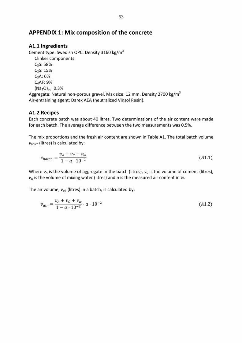
53
APPENDIX 1: Mix composition of the concrete
A1.1 Ingredients Cement type: Swedish OPC. Density 3160 kg/m3 Clinker components: C3S: 58% C2S: 15% C3A: 6% C4AF: 9% (Na2O)eq: 0.3% Aggregate: Natural non-porous gravel. Max size: 12 mm. Density 2700 kg/m3 Air-entraining agent: Darex AEA (neutralized Vinsol Resin).
A1.2 Recipes Each concrete batch was about 40 litres. Two determinations of the air content ware made for each batch. The average difference between the two measurements was 0,5%. The mix proportions and the fresh air content are shown in Table A1. The total batch volume vbatch (litres) is calculated by:
( )
Where vA is the volume of aggregate in the batch (litres), vC is the volume of cement (litres), vw is the volume of mixing water (litres) and a is the measured air content in %. The air volume, vair (litres) in a batch, is calculated by:
( )

54
Table A1: Mix proportions (based on the measured fresh air content). Concrete w/c Weight in batch
kg Volume in batch
litres Weight in concrete
kg/m3
qA qC qw vA vC vw air vbatch QA QC QW
% vair
11 0,424 54,8 25,0 10,6 20,3 7,9 10,6 3,5 1,4 40,2 1363 622 264
21 0,425 53,6 24,0 10,2 19,9 7,6 10,2 6,6 2,7 40,4 1327 594 252
31 0,426 53,4 23,0 9,8 19,8 7,3 9,8 8,0 3,2 40,1 1332 574 244
12 0,644 63,4 16,0 10,3 23,5 5,1 10,3 7,1 3,0 41,9 1513 382 246
22 0,642 69,8 17,3 11,1 25,9 5,5 11,1 11,5 5,5 48,0 1454 360 231
32 0,605 69,2 17,2 10,4 25,6 5,4 10,4 15,0 7,3 48,7 1421 353 214
13 0,701 70,0 15,4 10,8 25,9 4,9 10,8 5,7 2,5 44,1 1587 349 245 23 0,734 69,4 14,8 10,9 25,7 4,7 10,9 10,4 4,8 46,1 1505 321 236 33 0,741 70,5 13,5 10,0 26,1 4,3 10,0 11,0 5,0 45,4 1553 297 220
qA and QA: the weight of aggregate (kg/batch and kg/m3)
qC and QC: the weight of cement (kg/batch and kg/m3)
qw and QW: the weight of mixing water (kg/batch and kg/m3)
vA and VA: the volume of aggregate (l/batch and l/m3)
vC and VC: the volume of cement (l/batch and l/m3)
vw: the volume of mixing water (l/batch) vair: the volume of air (l/batch) vbatch: total volume of batch (l/batch)

55
APPENDIX 2: Degree of hydration The degree of hydration of the concrete before and after freeze-thaw was determined by igniting the pre-dried specimens at +1000°C. The specimen was crushed and ground in ethyl-alcohol in order to stop further hydration. A sample of the powdered specimen was dried at +105°C and weighed. Then, the powder was placed in a crucible which was placed in an oven where it was heated at + 1000°C. The amount of chemically bound water in hydrated cement wn (g) is calculated by: = (A2.1)
Where q105 and q1000 are the weight of the powder after drying and after ignition (g). The degree of hydration is obtained by dividing wn by the parameter 0,25C where C (g) is the cement content in the powder; see Eq. (1) in paragraph 3.1. Δq is the initial bound water in cement and aggregate before mixing. The value of Δq was determined by drying and igniting samples of aggregate and cement. The measured degree of hydration is listed in Table A2.1. Tabell A2.1: Degree of hydration before and after freezing.
Concrete
w/c air %
Degree of hydration, α
5 days 12 days 26 days 86 days
Before After Before After Before After Before After
11 0,424 3,5
0,46 0,47 0,57 0,55 0,60 - 0,65 -
21 0,425 6,6
0,50 0,50 0,56 0,56 0,61 - 0,66 -
31 0,426 8,0
0,48 0,49 0,55 0,56 0,60 - 0,68 -
12 0,644 7,1
0,51 0,51 0,57 0,58 0,64 - 0,70 -
22 0,642 11,5
0,52 0,55 0,60 0,60 0,65 - 0,75 -
32 0,605 15,0
0,35 0,37 0,43 0,41 0,47 - 0,48 -
13 0,701 5,7
0,50 0,54 0,61 0,60 0,68 - 0,78 -
23 0,734 10,4
0,53 0,52 0,64 0,66 0,72 - 0,78 -
33 0,741 11,0
0,51 0,52 0,61 0,63 0,70 - 0,76 -

56

57
APPENDIX 3. Density and porosity A3.1 Bulk density A discussion of the theoretically calculated -by Eq. (4)- and the measured bulk density and the difference between these two values is performed in paragraph 3.2.1. The two densities are given in Table A3.1. The theoretically calculated density is based on the air content of the fresh concrete. Table A3.1: Measured and theoretically calculated bulk density. Series w/c
air (%) Density (kg/m3)
Age
5 days 12 days 26 days 89 days
11 0,424 3,5
Measured Theoretical
2087 2057
2094 2072
2105 2078
2108 2086
21 0,425 6,6
Measured Theoretical
2044 1995
2051 2004
2043 2012
2073 2019
31 0,426 8,0
Measured Theoretical
2022 1975
2045 1985
2048 1992
2061 2007
12 0,644 7,1
Measured Theoretical
1996 1944
1984 1949
1988 1956
1999 1962
22 0,642 11,5
Measured Theoretical
1900 1862
1921 1868
1917 1873
1925 1882
32 0,605 15,0
Measured Theoretical
1732 1806
1734 1811
1751 1816
1752 1834
13 0,701 5,7
Measured Theoretical
1964 1981
1976 1989
1997 1995
2006 2004
23 0,734 10,4
Measured Theoretical
1919 1869
1927 1878
1938 1884
1943 1889
33 0,741 11,0
Measured Theoretical
1899 1888
1891 1896
1904 1902
1909 1906
In Figure A3.1-A3.3 the measured and theoretically calculated bulk density from Table A3.1 is plotted for all 9 concrete types. The bulk density increases with age which depends on the fact that more solid material is formed the higher the degree of hydration. The difference between measured and calculated density depends mainly on differences in the air content of the fresh and the hardened concrete. This is discussed in paragraph 3.2.1.

58
Figure A3.1: Bulk density. Series 11, 21, 31.
Figure A3.2: Bulk density. Series 12, 22, 32.
1500
1600
1700
1800
1900
2000
2100
2200
0 20 40 60 80 100
Den
sit
y,
kg
/m3
Age, days
Series 11
Theory
Measurement
1500
1600
1700
1800
1900
2000
2100
2200
0 20 40 60 80 100
Den
sit
y,
kg
/m3
Age, days
Series 21
Theory
Measurement
1500
1600
1700
1800
1900
2000
2100
2200
0 20 40 60 80 100
Den
sit
y,
kg
/m3
Age, days
Series 31
Theory
Measurement
1500
1600
1700
1800
1900
2000
2100
2200
0 20 40 60 80 100
Den
sit
y,
kg
/m3
Age, days
Series 12
Theory
Measurement
1500
1600
1700
1800
1900
2000
2100
2200
0 20 40 60 80 100
Den
sit
y,
kg
/m3
Age, days
Series 22
Theory
Measurement
1500
1600
1700
1800
1900
2000
2100
2200
0 20 40 60 80 100
Den
sit
y,
kg
/m3
Age, days
Series 32
Theory
Measurement

59
Figure A3.3: Bulk density. Series 13, 23, 33. A3.2 True density
The true density is calculated for all series and all ages using Eq. (10). The result is shown in Table A3.2. The true density decreases with increasing age which depends on the fact that dense cement is partially replaced by less dense hydration products. Table A3.2: Theoretically calculated true density of concrete. Series w/c
air (%) True density, (kg/m
3)
5 days 12 days 26 days 89 days
11 0,424 3,5
2720 2699 2690 2680
21 0,425 6,6
2711 2699 2688 2678
31 0,426 8,0
2715 2701 2691 2675
12 0,644 7,1
2706 2698 2688 2680
22 0,642 11,5
2703 2694 2687 2674
32 0,605 15,0
2727 2719 2712 2710
13 0,701 5,7
2704 2693 2684 2672
23 0,734 10,4
2703 2688 2680 2673
33 0,741 11,0
2705 2693 2684 2677
1500
1600
1700
1800
1900
2000
2100
2200
0 20 40 60 80 100
Den
sit
y,
kg
/m3
Age, days
Series 13
Theory
Measurement
1500
1600
1700
1800
1900
2000
2100
2200
0 20 40 60 80 100
Den
sit
y,
kg
/m3
Age, days
Series 23
Theory
Measurement
1500
1600
1700
1800
1900
2000
2100
2200
0 20 40 60 80 100
Den
sit
y k
g/m
3
Age, days
Series 33
Theory
Measurement

60
A3.3 Porosity The measured porosity for all series is given in Table A3.3. Table A3.3: Measured total porosity. Series w/c
air (%) Porosity, Pmeasured (m
3/m
3)
5 days 12 days 26 days 89 days
11 0,424 3,5
0,233 0,198 0,206 0,204
21 0,425 6,6
0,244 0,209 0,231 0,215
31 0,426 8,0
0,250 0,207 0,229 0,221
12 0,644 7,1
0,262 0,256 0,251 0,207
22 0,642 11,5
0,293 0,275 0,273 0,205
32 0,605 15,0
0,348 0,339 0,333 0,227
13 0,701 5,7
0,272 0,256 0,246 0,247
23 0,734 10,4
0,286 0,273 0,266 0,254
33 0,741 11,0
0,288 0,286 0,273 0,264
The theoretically calculated total porosity (m3/m3) based on the air content of the fresh concrete is shown in Table A3.4. The porosity is calculated by the following equation (the same as Eq. (8)):
(
)
Where C is the cement content (kg/m3), w/c the water-cement ratio, α the degree of hydration, 1000 the density of water (kg/m3) and Ao,fresh air the air content of the fresh concrete (m3/m3). As discussed in paragraph 3.2.2 there might be some errors in determination of porosity, which depends on difficulties to completely water-fill the entire pore system during the vacuum-absorption process. Indications of such errors are given above by Figure 7 and below by Figures A3.4-A3.6 where the effect of age on theoretically calculated porosity and measured porosity is plotted.

61
Table A3.4: Theoretically calculated porosity based on the air content of the fresh concrete. Series w/c
air (%) Ptheory,fresh (%)
5 days 12 days 26 days 89 days
11 0,424 3,5
0,242 0,23 0,226 0,219
21 0,425 6,6
0,26 0,253 0,247 0,242
31 0,426 8,0
0,269 0,261 0,256 0,247
12 0,644 7,1
0,277 0,272 0,267 0,263
22 0,642 11,5
0,307 0,302 0,299 0,292
32 0,605 15,0
0,336 0,332 0,329 0,328
13 0,701 5,7
0,264 0,258 0,253 0,247
23 0,734 10,4
0,304 0,297 0,292 0,289
33 0,741 11,0
0,298 0,292 0,287 0,284
Figure A3.4: Measured and theoretically calculated porosity based on fresh air content. Series 11, 21, 31.
0,18
0,2
0,22
0,24
0,26
0 20 40 60 80 100
Po
rosit
y
Age, days
Series 11
Theory
Measurement
0,2
0,22
0,24
0,26
0,28
0 20 40 60 80 100
Po
rosit
y
Age, days
Series 21
Theory
Measurement
0,2
0,22
0,24
0,26
0,28
0 20 40 60 80 100
Po
rosit
y
Age, days
Series 31
Theory
Measurement

62
Figure A3.5: Measured and theoretically calculated porosity based on fresh air content. Series 12, 22, 32.
Figure A3.6: Measured and theoretically calculated porosity based on fresh air content. Series 13, 23, 33.
0,2
0,22
0,24
0,26
0,28
0,3
0 20 40 60 80 100
Po
rosit
y
Age, days
Series 12
Theory
Measurement
0,2
0,22
0,24
0,26
0,28
0,3
0,32
0 20 40 60 80 100
Po
rosit
et
Age, days
Series 22
Theory
Measurement
0,2
0,22
0,24
0,26
0,28
0,3
0,32
0,34
0,36
0 20 40 60 80 100
Po
ros
ity
Age, days
Series 32
Theory
Measurement
0,24
0,25
0,26
0,27
0,28
0 20 40 60 80 100
Po
rosit
et
Age, days
Series 13
Theory
Measurement
0,24
0,26
0,28
0,3
0,32
0 20 40 60 80 100
Po
rosit
et
Age, days
Series 23
Theory
Measurement
0,26
0,27
0,28
0,29
0,3
0 20 40 60 80 100
Po
rosit
y
Age, days
Series 33
Theory
Measurement

63
The true porosity based on bulk density and true density is calculated by Eq. (9) and is listed in Table A3.5. Table A3.5: True porosity. Series w/c
air (%)
Ptrue (%)
5 days 12 days 26 days 89 days
11 0,424 3,5
0,233 0,224 0,217 0,213
21 0,425 6,6
0,246 0,240 0,240 0,226
31 0,426 8,0
0,255 0,243 0,239 0,230
12 0,644 7,1
0,262 0,265 0,260 0,256
22 0,642 11,5
0,297 0,287 0,287 0,280
32 0,605 15,0
0,365 0,362 0,354 0,354
13 0,701 5,7
0,274 0,266 0,256 0,250
23 0,734 10,4
0,290 0,283 0,277 0,273
33 0,741 11,0
0,300 0,298 0,291 0,287
The relation between the true porosity and the measured is plotted in Figures A4.7-A4.9.
Figure A3.7: Measured and true porosity. Series 11, 21, 31.
0,18
0,2
0,22
0,24
0,26
0,28
0,3
0 20 40 60 80 100
Po
rosit
y
Age, days
Series 11
From density
Measurement
0,2
0,22
0,24
0,26
0,28
0,3
0,32
0 20 40 60 80 100
Po
rosit
y
Age, days
Series 21
From density
Measurement
0,2
0,22
0,24
0,26
0,28
0,3
0,32
0 20 40 60 80 100
Po
rosit
y
Age, days
Series 31
From density
Measurement

64
Figure A3.8: Measured and true porosity. Series 12, 22, 32.
Figure A3.9: Measured and true porosity. Series 13, 23, 33.
0,2
0,22
0,24
0,26
0,28
0,3
0,32
0 20 40 60 80 100
Po
rosit
y
Age, days
Series 12
From density
Measurement
0,2
0,22
0,24
0,26
0,28
0,3
0,32
0 20 40 60 80 100
Po
rosit
et
Age, days
Series 22
From density
Measurement
0,2
0,22
0,24
0,26
0,28
0,3
0,32
0,34
0,36
0,38
0 20 40 60 80 100
Po
rosit
y
Age, days
Series 32
From density
Measurement
0,24
0,26
0,28
0,3
0,32
0,34
0,36
0 20 40 60 80 100
Po
rosit
et
Age, days
Series 13
From density
Measurement0,24
0,26
0,28
0,3
0,32
0,34
0,36
0 20 40 60 80 100
Po
rosit
et
Age, days
Series 23
From density
Measurement
0,26
0,28
0,3
0,32
0,34
0,36
0,38
0 20 40 60 80 100
Po
ros
ity
Age, days
Series 33
From density
Measurement
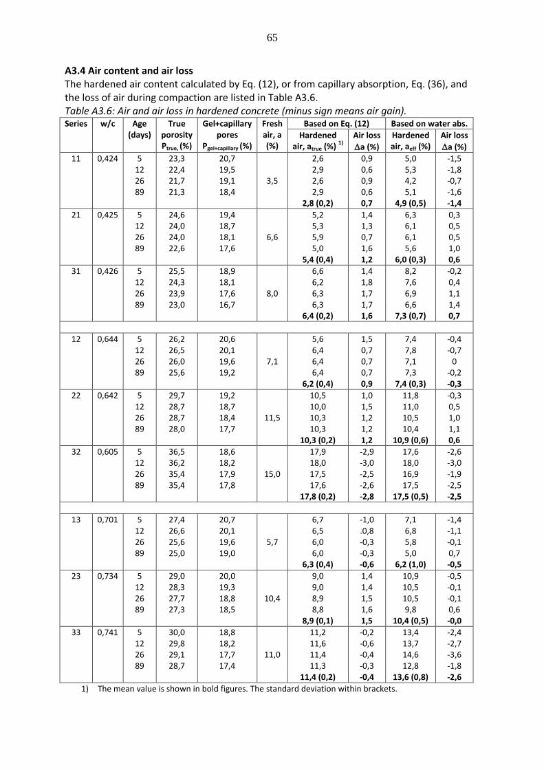
65
A3.4 Air content and air loss The hardened air content calculated by Eq. (12), or from capillary absorption, Eq. (36), and the loss of air during compaction are listed in Table A3.6. Table A3.6: Air and air loss in hardened concrete (minus sign means air gain). Series w/c Age
(days) True
porosity Ptrue, (%)
Gel+capillary pores
Pgel+capillary (%)
Fresh air, a (%)
Based on Eq. (12) Based on water abs.
Hardened air, atrue (%)
1)
Air loss
a (%)
Hardened air, aeff (%)
Air loss
a (%)
11 0,424 5 12 26 89
23,3 22,4 21,7 21,3
20,7 19,5 19,1 18,4
3,5
2,6 2,9 2,6 2,9
2,8 (0,2)
0,9 0,6 0,9 0,6 0,7
5,0 5,3 4,2 5,1
4,9 (0,5)
-1,5 -1,8 -0,7 -1,6 -1,4
21 0,425 5 12 26 89
24,6 24,0 24,0 22,6
19,4 18,7 18,1 17,6
6,6
5,2 5,3 5,9 5,0
5,4 (0,4)
1,4 1,3 0,7 1,6 1,2
6,3 6,1 6,1 5,6
6,0 (0,3)
0,3 0,5 0,5 1,0 0,6
31 0,426 5 12 26 89
25,5 24,3 23,9 23,0
18,9 18,1 17,6 16,7
8,0
6,6 6,2 6,3 6,3
6,4 (0,2)
1,4 1,8 1,7 1,7 1,6
8,2 7,6 6,9 6,6
7,3 (0,7)
-0,2 0,4 1,1 1,4 0,7
12 0,644 5 12 26 89
26,2 26,5 26,0 25,6
20,6 20,1 19,6 19,2
7,1
5,6 6,4 6,4 6,4
6,2 (0,4)
1,5 0,7 0,7 0,7 0,9
7,4 7,8 7,1 7,3
7,4 (0,3)
-0,4 -0,7
0 -0,2 -0,3
22 0,642 5 12 26 89
29,7 28,7 28,7 28,0
19,2 18,7 18,4 17,7
11,5
10,5 10,0 10,3 10,3
10,3 (0,2)
1,0 1,5 1,2 1,2 1,2
11,8 11,0 10,5 10,4
10,9 (0,6)
-0,3 0,5 1,0 1,1 0,6
32 0,605 5 12 26 89
36,5 36,2 35,4 35,4
18,6 18,2 17,9 17,8
15,0
17,9 18,0 17,5 17,6
17,8 (0,2)
-2,9 -3,0 -2,5 -2,6 -2,8
17,6 18,0 16,9 17,5
17,5 (0,5)
-2,6 -3,0 -1,9 -2,5 -2,5
13 0,701 5 12 26 89
27,4 26,6 25,6 25,0
20,7 20,1 19,6 19,0
5,7
6,7 6,5 6,0 6,0
6,3 (0,4)
-1,0 .0,8 -0,3 -0,3 -0,6
7,1 6,8 5,8 5,0
6,2 (1,0)
-1,4 -1,1 -0,1 0,7 -0,5
23 0,734 5 12 26 89
29,0 28,3 27,7 27,3
20,0 19,3 18,8 18,5
10,4
9,0 9,0 8,9 8,8
8,9 (0,1)
1,4 1,4 1,5 1,6 1,5
10,9 10,5 10,5 9,8
10,4 (0,5)
-0,5 -0,1 -0,1 0,6 -0,0
33 0,741 5 12 26 89
30,0 29,8 29,1 28,7
18,8 18,2 17,7 17,4
11,0
11,2 11,6 11,4 11,3
11,4 (0,2)
-0,2 -0,6 -0,4 -0,3 -0,4
13,4 13,7 14,6 12,8
13,6 (0,8)
-2,4 -2,7 -3,6 -1,8 -2,6
1) The mean value is shown in bold figures. The standard deviation within brackets.

66
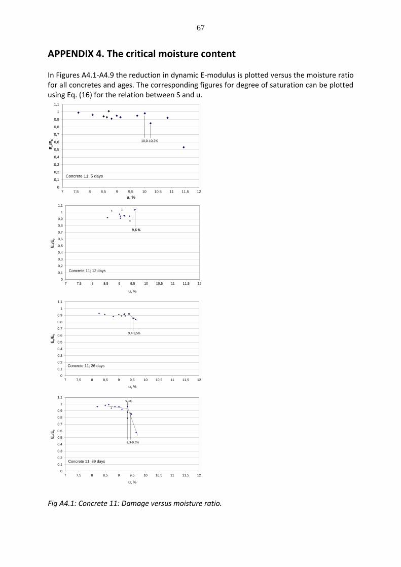
67
APPENDIX 4. The critical moisture content
In Figures A4.1-A4.9 the reduction in dynamic E-modulus is plotted versus the moisture ratio for all concretes and ages. The corresponding figures for degree of saturation can be plotted using Eq. (16) for the relation between S and u.
Fig A4.1: Concrete 11: Damage versus moisture ratio.
0
0,1
0,2
0,3
0,4
0,5
0,6
0,7
0,8
0,9
1
1,1
7 7,5 8 8,5 9 9,5 10 10,5 11 11,5 12
En/E
0
u, %
Concrete 11; 5 days
10,0-10,2%
0
0,1
0,2
0,3
0,4
0,5
0,6
0,7
0,8
0,9
1
1,1
7 7,5 8 8,5 9 9,5 10 10,5 11 11,5 12
En/E
0
u, %
Concrete 11; 12 days
9,6 %
0
0,1
0,2
0,3
0,4
0,5
0,6
0,7
0,8
0,9
1
1,1
7 7,5 8 8,5 9 9,5 10 10,5 11 11,5 12
En/E
0
u, %
Concrete 11; 26 days
9,4-9,5%
0
0,1
0,2
0,3
0,4
0,5
0,6
0,7
0,8
0,9
1
1,1
7 7,5 8 8,5 9 9,5 10 10,5 11 11,5 12
En/E
0
u, %
Concrete 11; 89 days
9,3-9,5%
9,3%

68
Fig A4.2: Concrete 21: Damage versus moisture ratio.
0
0,1
0,2
0,3
0,4
0,5
0,6
0,7
0,8
0,9
1
1,1
7 7,5 8 8,5 9 9,5 10 10,5 11 11,5 12 12,5
En/E
0
u, %
Concrete 21; 5 days
11,2-11,5%
0
0,1
0,2
0,3
0,4
0,5
0,6
0,7
0,8
0,9
1
1,1
7 7,5 8 8,5 9 9,5 10 10,5 11 11,5 12
En/E
0
u, %
Concrete 21; 12 days
10,7 %
0
0,1
0,2
0,3
0,4
0,5
0,6
0,7
0,8
0,9
1
1,1
7 7,5 8 8,5 9 9,5 10 10,5 11 11,5 12
En/E
0
u, %
Concrete 21; 26 days
10,1-10,3%
0
0,1
0,2
0,3
0,4
0,5
0,6
0,7
0,8
0,9
1
1,1
7 7,5 8 8,5 9 9,5 10 10,5 11 11,5 12
En/E
0
u, %
Concrete 21; 89 days
10,0%

69
Fig A4.3: Concrete 31: Damage versus moisture ratio.
0
0,1
0,2
0,3
0,4
0,5
0,6
0,7
0,8
0,9
1
1,1
7 7,5 8 8,5 9 9,5 10 10,5 11 11,5 12 12,5
En/E
0
u, %
Concrete 31; 5 days
11,4-11,8%
0
0,1
0,2
0,3
0,4
0,5
0,6
0,7
0,8
0,9
1
1,1
7 7,5 8 8,5 9 9,5 10 10,5 11 11,5 12 12,5
En/E
0
u, %
Concrete 31; 12 days
10,8-10,9%
0
0,1
0,2
0,3
0,4
0,5
0,6
0,7
0,8
0,9
1
1,1
7 7,5 8 8,5 9 9,5 10 10,5 11 11,5 12 12,5
En/E
0
u,%
Concrete 31; 26 days
10,0% 10,6%
10,6%
0
0,1
0,2
0,3
0,4
0,5
0,6
0,7
0,8
0,9
1
1,1
7 7,5 8 8,5 9 9,5 10 10,5 11 11,5 12 12,5
En/E
0
u, %
Concrete 31; 89 days
10,2%

70
Fig A4.4: Concrete 12: Damage versus moisture ratio.
0
0,1
0,2
0,3
0,4
0,5
0,6
0,7
0,8
0,9
1
1,1
7 7,5 8 8,5 9 9,5 10 10,5 11 11,5 12 12,5 13 13,5 14 14,5 15
En/E
0
u, %
Concrete 12, 5 days
10,6% 11,4%
0
0,1
0,2
0,3
0,4
0,5
0,6
0,7
0,8
0,9
1
1,1
7 7,5 8 8,5 9 9,5 10 10,5 11 11,5 12 12,5 13 13,5 14
En/E
0
u, %
Concrete 12; 12 days
11,6%
11,3%
0
0,1
0,2
0,3
0,4
0,5
0,6
0,7
0,8
0,9
1
1,1
7 7,5 8 8,5 9 9,5 10 10,5 11 11,5 12 12,5 13 13,5 14
En/E
0
u %
Concrete 12; 26 days
11,1-11,5%
11,0%
0
0,1
0,2
0,3
0,4
0,5
0,6
0,7
0,8
0,9
1
1,1
7 7,5 8 8,5 9 9,5 10 10,5 11 11,5 12 12,5 13
En/E
0
u, %
Concrete 12, 89 days
10,6-11,0%

71
Fig A4.5: Concrete 22: Damage versus moisture ratio.
0
0,1
0,2
0,3
0,4
0,5
0,6
0,7
0,8
0,9
1
1,1
6 7 8 9 10 11 12 13 14 15 16
En/E
0
u, %
Concrete 22; 5 days
12,7 - 13,3%
0
0,1
0,2
0,3
0,4
0,5
0,6
0,7
0,8
0,9
1
1,1
7 8 9 10 11 12 13 14 15 16
En/E
0
u, %
Concrete 22; 12 days
12,7-13,0%
0
0,1
0,2
0,3
0,4
0,5
0,6
0,7
0,8
0,9
1
1,1
7 8 9 10 11 12 13 14 15
En/E
0
u, %
Concrete 22; 26 days
13,4-13,8%
13,3%
0
0,1
0,2
0,3
0,4
0,5
0,6
0,7
0,8
0,9
1
1,1
7 8 9 10 11 12 13 14 15 16
En/E
0
u, %
Concrete 22; 89 days
12,2-12,5%

72
Fig A4.6: Concrete 32: Damage versus moisture ratio.
0
0,1
0,2
0,3
0,4
0,5
0,6
0,7
0,8
0,9
1
1,1
10 11 12 13 14 15 16 17 18 19 20 21 22
En/E
0
u,%
Concrete 32; 5 days
18,1-18,5%
0
0,1
0,2
0,3
0,4
0,5
0,6
0,7
0,8
0,9
1
1,1
10 11 12 13 14 15 16 17 18 19 20 21 22
En/E
0
u, %
Concrete 32; 12 days
>19,8 %
0
0,1
0,2
0,3
0,4
0,5
0,6
0,7
0,8
0,9
1
1,1
10 11 12 13 14 15 16 17 18 19 20 21 22
En/E
0
u, %
Concrete 32; 26 days
17,8-18,6%
0
0,1
0,2
0,3
0,4
0,5
0,6
0,7
0,8
0,9
1
1,1
10 11 12 13 14 15 16 17 18 19 20
En/E
0
u, %
Concrete 32; 89 days
17,7%

73
Fig A4.7: Concrete 13: Damage versus moisture ratio.
0
0,1
0,2
0,3
0,4
0,5
0,6
0,7
0,8
0,9
1
1,1
7 8 9 10 11 12 13 14
En/E
0
u,%
Concrete 13; 5 days
10,3%
10,7-10,8%
0
0,1
0,2
0,3
0,4
0,5
0,6
0,7
0,8
0,9
1
1,1
7 8 9 10 11 12 13 14
En/E
0
u, %
Concrete 13; 12 days
11,1%
0
0,1
0,2
0,3
0,4
0,5
0,6
0,7
0,8
0,9
1
1,1
7 8 9 10 11 12 13
En/E
0
u,%
Concrete 13; 26 days
11,3%
0
0,1
0,2
0,3
0,4
0,5
0,6
0,7
0,8
0,9
1
1,1
7 8 9 10 11 12 13
En/E
0
u, %
Concrete 13; 89 days
10,6 %

74
Fig A4.8: Concrete 23: Damage versus moisture ratio.
0
0,1
0,2
0,3
0,4
0,5
0,6
0,7
0,8
0,9
1
1,1
8 9 10 11 12 13 14 15 16
En/E
0
u,%
Concrete 23; 5 days
12,6%
12,8-13,2%
0
0,1
0,2
0,3
0,4
0,5
0,6
0,7
0,8
0,9
1
1,1
9 10 11 12 13 14 15
En/E
0
u, %
Concrete 23; 12 days
13,5-13,8%
0
0,1
0,2
0,3
0,4
0,5
0,6
0,7
0,8
0,9
1
1,1
9 10 11 12 13 14 15
En/E
0
u, %
Concrete 23; 26 days
13,1-13,3%
0
0,1
0,2
0,3
0,4
0,5
0,6
0,7
0,8
0,9
1
1,1
9 10 11 12 13 14 15
En/E
0
u,%
Concrete 23; 89 days
11,6% 12,2%
11,7%

75
Fig A4.9: Concrete 33: Damage versus moisture ratio.
0
0,1
0,2
0,3
0,4
0,5
0,6
0,7
0,8
0,9
1
1,1
8 9 10 11 12 13 14 15 16
En/E
0
u, %
Concrete 33; 5 days
13,7 %
0
0,1
0,2
0,3
0,4
0,5
0,6
0,7
0,8
0,9
1
1,1
8 9 10 11 12 13 14 15 16
En/E
0
u, %
Concrete 33; 12 days
14,8 %
0
0,1
0,2
0,3
0,4
0,5
0,6
0,7
0,8
0,9
1
1,1
8 9 10 11 12 13 14 15 16
En/E
0
u, %
Concrete 33; 26 days
13,7-14,1%
13,6%
0
0,1
0,2
0,3
0,4
0,5
0,6
0,7
0,8
0,9
1
1,1
8 9 10 11 12 13 14 15
En/E
0
u, %
Concrete 33; 89 days
13,2-13,7%

76

77
APPENDIX 5. Relation between the critical moisture content and the moisture content at capillary saturation The capillary degree of saturation, S0, is defined by Eq. (19). It corresponds to a situation where all pores except the air-pores are water-filled. It is always a bit lower than the critical degree of saturation, which indicates that part of the air-pore system has to be water-filled for frost damage to occur. A comparison between So and SCR for all 9 concrete types and all concrete ages is shown in Figures A51-A5.9.
Figure A5.1: So and SCR for concrete series 11.
Figure A5.2: So and SCR for concrete series 21.
Figure A5.3: So and SCR for concrete series 31.
0
0,1
0,2
0,3
0,4
0,5
0,6
0,7
0,8
0,9
1
0 20 40 60 80 100
S
Age (days)
Concrete 11
SCR
S
S0
0
0,1
0,2
0,3
0,4
0,5
0,6
0,7
0,8
0,9
1
0 20 40 60 80 100
S
Age (days)
Concrete 21
SCR
S0
0
0,1
0,2
0,3
0,4
0,5
0,6
0,7
0,8
0,9
1
0 20 40 60 80 100
S
Age (days)
Concrete 31
SCR
S0

78
Figure A5.4: So and SCR for concrete series 12.
Figure A5.5: So and SCR for concrete series 22.
Figure A5.6: So and SCR for concrete series 32.
0
0,1
0,2
0,3
0,4
0,5
0,6
0,7
0,8
0,9
1
0 20 40 60 80 100
S
Age (days)
Concrete 12
SCR
S0
0
0,1
0,2
0,3
0,4
0,5
0,6
0,7
0,8
0,9
1
0 20 40 60 80 100
S
Age (days)
Concrete 22
SCR
S0
0
0,1
0,2
0,3
0,4
0,5
0,6
0,7
0,8
0,9
1
0 20 40 60 80 100
S
Age (days)
Concrete 32
SCR
S0

79
Figure A5.7: So and SCR for concrete series 13.
Figure A5.8: So and SCR for concrete series 23.
Figure A5.9: So and SCR for concrete series 33.
0
0,1
0,2
0,3
0,4
0,5
0,6
0,7
0,8
0,9
1
0 20 40 60 80 100
S
Age (days)
Concrete 13
SCR
S0
0
0,1
0,2
0,3
0,4
0,5
0,6
0,7
0,8
0,9
1
0 20 40 60 80 100
S
Age
Concrete 23
SCR
S0
0
0,1
0,2
0,3
0,4
0,5
0,6
0,7
0,8
0,9
1
0 20 40 60 80 100
S
Age (days)
Concrete 33
SCR
S0

80
The moisture content can also be expressed in terms of moisture ratio. The moisture ratio closely corresponding to capillary saturation un defined by Figure 25 and the critical moisture ratio uCR are plotted in Figures A5.10-A5.19.
Figure A5.10: un and uCR for concrete series 11.
Figure A5.11: un and uCR for concrete series 21.
Figure A5.12: un and uCR for concrete series 31.
0
1
2
3
4
5
6
7
8
9
10
11
0 20 40 60 80 100
Mo
istu
re r
ati
o,
%
Age, days
Concrete 11
U0
UCR
0
1
2
3
4
5
6
7
8
9
10
11
12
0 20 40 60 80 100
Mo
istu
re r
ati
o,
%
Age, days
Concrete 21
U0
UCR
0
1
2
3
4
5
6
7
8
9
10
11
12
13
0 20 40 60 80 100
Mo
istu
re r
ati
o,
%
Age, days
Concrete 31
U0
UCR

81
Figure A5.14: un and uCR for concrete series 12.
Figure A5.15: un and uCR for concrete series 22.
Figure A5.16: un and uCR for concrete series 32.
0
1
2
3
4
5
6
7
8
9
10
11
12
0 20 40 60 80 100
Mo
istu
re r
ati
o, %
Age, days
Concrete 12
U0
UCR
0
1
2
3
4
5
6
7
8
9
10
11
12
13
14
0 20 40 60 80 100
Mo
istu
re r
ati
o, %
Age, days
Concrete 22
U0
UCR
0
2
4
6
8
10
12
14
16
18
20
0 20 40 60 80 100
Mo
istu
re r
ati
o,
%
Age, days
Concrete 32
U0
UCR

82
Figure A5.17: un and uCR for concrete series 13.
Figure A5.18: un and uCR for concrete series 23.
Figure A5.19: un and uCR for concrete series 33.
0
1
2
3
4
5
6
7
8
9
10
11
12
0 20 40 60 80 100
Mo
istu
re r
ati
o,
%
Age, days
Concrete 13
U0
UCR
0
1
2
3
4
5
6
7
8
9
10
11
12
13
14
15
0 20 40 60 80 100
Mo
istu
re r
ati
o,
%
Age, days
Concrete 23
U0
UCR
0
1
2
3
4
5
6
7
8
9
10
11
12
13
14
15
0 20 40 60 80 100
Mo
istu
re r
ati
o, %
Age, days
Concrete 33
U0
UCR

83
APPENDIX 6. Adjustment of moisture in specimens for freeze-thaw
A6.1 Specimen weight before freezing Degree of saturation S is defined:
(A6.1)
Where we is the volume of water in the specimen (cm3), and vp is the pore volume in the specimen (cm3). The pore volume in the specimen is: (A6.2)
Where P is the total porosity (cm3/cm3) and v is the specimen volume (cm3). The exact porosity and specimen volume are not known in advance. Approximate values have to be used. An approximate value of the porosity of the concrete (litre/litre) is calculated by:
(A6.3)
Where vw is the amount of mixing water in the batch (litres), wn is the chemically bound water (kg), vair is the air content in the batch (litres). 0,75 is the specific volume of chemically bound water (l/kg). vbatch is the volume of the concrete batch (litres). No volume change of the specimen caused by hydration or drying is assumed to take place. wn is calculated from the assumed degree of hydration α. (A6.4) Where qc is the cement content in the batch (kg). vbatch is calculated from the mix proportions: (A6.5)
Where va and vC is the volume of aggregate and cement (litres). An approximate value of the volume v of a specimen (cm3) is calculated by:
(A6.6)

84
Where qspec is the wet weight of the specimens when removed from water storage after 2, 9,
26 or 86 days (g); see Figure 2. w is the corresponding wet density (g/cm3). The wet density (kg/litre or g/cm3) is calculated by:
(A6.7)
Where qbatch,dry is the weight of the concrete batch when dried (kg), qw is the amount of mixing water in the batch (kg), qabs is the water sucked in due to the 25% chemical contraction of hydrate water, qwn is the amount of chemically bound water in the batch (depends on degree of hydration) (kg). qbatch,dry is : (A6.8)
Where qA (kg) and qC (kg) are the weight of aggregate and cement in the batch. The specimen weight corresponding to degree of saturation S is: (A6.9)
Where qw is the amount of water in the specimen (g), qd is the specimen weight at total drying (g). It is calculated by: (A6.10)
Where d is the dry density (kg/litre or g/cm3). It is calculated by:
(A5.11)
All data in the equations are known from the mix proportions and from the weight of the water-stored specimen. Example: Required degree of saturation, S=0,80
From mix proportions: qA=54,8 kg vA=20,8 litres qC=25,0 kg vC=7,9 litres
vw=10,0 litres vair=1,40 litres vbatch=20,8+7,9+10,0+1,40=40,1 litres
assumed α=0,54 gives qwn=0,250,5425=3,4 kg qbatch,dry=54,8+25,0+3,4=83,2 kg

85
Specimen: qspec=603,5 g (measured after water storage and before freeze-thaw)
Thus, a certain drying of the water stored specimen (2,5 g) has to take place until S=0,80 is reached.
A6.2 Calculation of the true degree of saturation of each specimen For calculation of the true value of degree of saturation for each specimen made after terminated freeze-thaw, the average values of bulk density and porosity are used. These data are listed in APPENDIX 3. The volume, V (cm3) of each specimen is:
(A6.12)
Where qd (g) is the dry weight of the specimen, and
is the dry density (g/cm3) obtained
from Table A3.1. The pore volume vp (cm3) of each specimen is: (A6.13)
Where P is the porosity (cm3/cm3) obtained from Table A3.5. The water content in the specimen is: (A6.14)
Where q1 (g) is the specimen weight during freeze-thaw.

86
The degree of saturation becomes:
(A6.15)
q1 and qd are determined experimentally for each specimen. P and are mean values for the actual concrete mix. The values are shown in Table A3.5 and A3.1. Example Series 11, 26 days curing:
q1=605,2 g (pre-determined and used value. Expected S=0,82) qd=559,1 g P=0,206 cm3/cm3
=2,105 g/cm3
Instead of the pre-calculated degree of saturation 0,82, the true value became 0,84. The reason is that the porosity was over-estimated and/or the density under-estimated by the formulas in paragraph A6.1.

87
APPENDIX 7. Capillary absorption Capillary absorption curves for all concrete specimens are shown in Figures A7.1-A9.9. In most cases four specimens were tested for all concrete series and age. The lines drawn in the figures are the mean for all specimens. They were calculated by the method of least squares. All results evaluated from the figures are listed in Table A7.1. Values of m, k and C are calculated by equations in paragraph 5.3. Table A7.1: Results of capillary absorption experiment. Concrete Age
days H m
A m
2
tn s
un kg/kg
uo kg/kg
m Eq.(28)
s/m2
k Eq.(32)
kg/m2s
½
B Eq.(34)
%
C Eq.(34)
kg/kgmin½
11
air 2,8%
5 0,019 6,410-3
12480 0,0878 0,0579 3,46107 10,1 8,8 6,210
-3
12 22800 0,0815 0,0591 6,32107 22,9 8,0 6,610
-3
26 17820 0,0833 0,0334 4,94107 14,7 8,3 4,610
-3
89 16800 0,0768 0,0199 4,65107 17,4 7,6 6,910
-3
21
air 5,4%
5 0,019 6,410-3
15960 0,0894 0,0596 4,42107 9,4 8,8 7,910
-3
12 14640 0,0871 0,0453 4,06107 13,8 8,6 3,710
-3
26 22500 0,0874 0,0460 6,23107 10,8 8,7 3,010
-3
89 14040 0,0820 0,0232 3,89107 18,9 8,1 5,210
-3
31
air 6,4%
5 0,019 6,410-3
14460 0,0858 0,0566 4,01107 9,6 8,5 6,110
-3
12 12840 0,0817 0,0411 3,56107 14,0 8,1 4,410
-3
26 24660 0,0831 0,0404 6,83107 10,7 8.3 7,510
-4
89 11700 0,0796 0,0265 3,24107 19,3 7,9 4,110
-3
12
air 6,2%
5 0,019 6,410-3
2220 0,0942 0,0334 6,15106 47,9 9,4 4,110
-3
12 6060 0,0933 0,0219 1,68107 34,3 9,3 6,410
-3
26 8340 0,0949 0,0244 2,31107 28,8 9,4 4,910
-3
89 11100 0,0914 0,0204 3,07107 25,6 9,1 3,710
-3
22
air 10,3%
5 0,019 6,410-3
1980 0,0943 0,0454 5,48106 40,7 9,4 4,110
-3
12 5820 0,0921 0,0261 1,61107 30,9 9,2 4,510
-3
26 8760 0,0949 0,0292 2,43107 24,7 9,5 1,810
-3
89 10620 0,0915 0,0257 2,94107 22,7 9,1 4,110
-3
32
air 17,8%
5 0,019 6,410-3
2220 0,1090 0,0340 6,15106 52,7 10,9 4,210
-3
12 0,04 3,210-3
12360 0,1047 0,0202 7,73106 52,1 10,5 1,210
-3
26 17580 0,1057 0,0098 1,10107 50,9 10,6 1,210
-3
89 33060 0,1021 0,0141 2,07107 33,7 10,1 3,410
-3
13
air 6,3%
5 0,019 6,410-3
840 0,1033 0,0076 2,32106 121,1 10,3 8,910
-3
12 1620 0,1000 0,0089 4,49107 83,1 10,0 4,810
-3
26 5700 0,0963 0,0031 1,58107 45,4 9,5 8,410
-3
89 7200 0,0996 0,0267 1,99107 31,9 9,9 6,810
-3
23
air 8,9%
5 0,04 3,210-3
31200 0,0942 0,0329 1,95107 27,3 9,3 3,510
-3
12 28980 0,0924 0,0153 1,81107 35,3 9,2 4,110
-3
26 37980 0,0889 0,0154 2,37107 29,2 9,7 9,510
-3
89 29100 0,0900 0,0075 1,82107 38,0 8,9 4,510
-3
33
air 11,4%
5 0,04 3,210-3
41220 0,0874 0,0308 2,58107 20,9 8,6 4,110
-3
12 38940 0,0849 0,0146 2,43107 29,0 8,3 7,610
-3
26 51120 0,0759 0,0151 3,20107 21,4 7,0 2,110
-2
89 39060 0,0835 0,0235 2,44107 24,7 8,1 7,910
-3

88
Figure A7.1: Capillary absorption for series 11.
0
1
2
3
4
5
6
7
8
9
10
0 10 20 30 40 50 60
uC
AP
(%
)
Absorption time, square-root scale (min1/2)
Age 5 days
=8,78 %
0,786=208 min
0
1
2
3
4
5
6
7
8
9
10
0 10 20 30 40 50 60
uC
AP
(%)
Absorption time, square-root scale (min1/2)
12 days
0,762
0
1
2
3
4
5
6
7
8
9
10
0 10 20 30 40 50 60
uC
AP
(%)
Absorption time, square-root scale (min1/2)
26 days
0,808
0
1
2
3
4
5
6
7
8
9
0 10 20 30 40 50 60
uC
AP
(%)
Absorption time, square-root scale (min1/2)
89 days
0,760

89
Figure A7.2: Capillary absorption for series 21.
0
1
2
3
4
5
6
7
8
9
10
0 10 20 30 40 50 60
uC
AP
(%)
Absorption time, square-root scale (min1/2)
5 days
%0,743
0
1
2
3
4
5
6
7
8
9
10
0 10 20 30 40 50 60
uC
AP
(%)
Absorption time, square-root scale (min1/2)
12 days
0,744
0
1
2
3
4
5
6
7
8
9
10
0 10 20 30 40 50 60
uC
AP
(%)
Absorption time, square-root scale (min1/2)
26 days
0
1
2
3
4
5
6
7
8
9
0 10 20 30 40 50 60
uC
AP
(%)
Absorption time, square-root scale (min1/2)
89 days
0,752

90
Figure A7.3: Capillary absorption for series 31.
0
1
2
3
4
5
6
7
8
9
10
0 10 20 30 40 50 60
uC
AP
(%)
Absorption time, square-root scale (min1/2)
5 days
0,680
0
1
2
3
4
5
6
7
8
9
0 10 20 30 40 50 60
uC
AP
(%)
Absorption time, square-root scale (min1/2)
12 days
0,688
0
1
2
3
4
5
6
7
8
9
0 10 20 30 40 50 60
uC
AP
(%)
Absorption time, square-root scale (min1/2)
26 days
0,712
0
1
2
3
4
5
6
7
8
9
0 10 20 30 40 50 60
uC
AP
(%)
Absorption time, square-root scale (min1/2)
89 days
=7,96 %0,713
=195 min

91
Figure A7.4: Capillary absorption for series 12.
0
1
2
3
4
5
6
7
8
9
10
11
0 10 20 30 40 50 60
uC
AP
(%)
Absorption time, square-root scale (min1/2)
5 days
0,718
0
1
2
3
4
5
6
7
8
9
10
11
0 10 20 30 40 50 60
uC
AP
(%)
Absorption time, square-root scale (min1/2)
12 days
0,699
0
1
2
3
4
5
6
7
8
9
10
11
0 10 20 30 40 50 60
uC
AP
(%
)
Absorption time, square-root scale (min1/2)
26 days
0,726
0
1
2
3
4
5
6
7
8
9
10
11
0 20 40 60 80 100
uC
AP
(%
)
Absorption time, square-root scale (min1/2)
89 days
0,714

92
Figure A7.5: Capillary absorption for series 22.
0
1
2
3
4
5
6
7
8
9
10
11
0 10 20 30 40 50 60
uC
AP
(%
)
Absorption time, square-root scale (min1/2)
5 days
0,603
0
1
2
3
4
5
6
7
8
9
10
0 10 20 30 40 50 60
uC
AP
(%)
Absorption time, square-root scale (min1/2)
12 days
0,616
0
1
2
3
4
5
6
7
8
9
10
11
0 10 20 30 40 50 60
uC
AP
(%)
Absorption time, square-root scle (min1/2)
26 days
0,634
0
1
2
3
4
5
6
7
8
9
10
0 20 40 60 80 100
uC
AP
(%)
Absorption time, square-root scale (min1/2)
89 days
0,629

93
Figure A7.6: Capillary absorption for series 32.
0
1
2
3
4
5
6
7
8
9
10
11
12
0 10 20 30 40 50 60
uC
AP
(%)
Absorption time, square-root scale (min1/2)
5 days
0,517
0
1
2
3
4
5
6
7
8
9
10
11
12
0 10 20 30 40 50 60
uC
AP
(%)
Absorption time, square-root scale (min1/2)
12 days
0,502
0
1
2
3
4
5
6
7
8
9
10
11
12
0 10 20 30 40 50 60
uC
AP
(%)
Absorption time, square-root scale (min1/2)
26 days
0,523
0
1
2
3
4
5
6
7
8
9
10
11
12
0 20 40 60 80 100
uC
AP
(%
)
Absorption time, square-root scale (min1/2)
89 days
0,505

94
Figure A7.7: Capillary absorption for series 13.
0
1
2
3
4
5
6
7
8
9
10
11
12
0 10 20 30 40 50 60
uC
AP
(%
)
Absorption time, square-root scale (min1/2)
Age 5 days
0,740
0
1
2
3
4
5
6
7
8
9
10
11
0 10 20 30 40 50 60
uC
AP
(%)
Absorption time, square-root scale (min1/2)
12 dygn
Age 12 days
0,743
0
1
2
3
4
5
6
7
8
9
10
11
0 10 20 30 40 50 60
uC
AP
(%)
Absorption time, square-root scale (min1/2)
Age 26 days
0,773
0
1
2
3
4
5
6
7
8
9
10
11
12
0 20 40 60 80 100
uC
AP
(%
)
Absorption time, square-root scale (min1/2)
Age 89 days
0,799

95
Figure A7.8: Capillary absorption for series 23.
0
1
2
3
4
5
6
7
8
9
10
11
0 10 20 30 40 50 60
uC
AP(%
)
Absorption time, square-root scale (min1/2)
5 days
0,623
0
1
2
3
4
5
6
7
8
9
10
0 10 20 30 40 50 60
uC
AP
(%)
Absorption time, square-root scale (min1/2)
12 days
0,629
0
1
2
3
4
5
6
7
8
9
10
0 10 20 30 40 50 60
uC
AP
(%)
Absorption time, square-root scale (min1/2)
26 days
0,622
0
1
2
3
4
5
6
7
8
9
10
0 20 40 60 80 100
uC
AP
(%)
Absorption time, square-root scale (min1/2)
89 days

96
Figure A7.9: Capillary absorption for series 33.
0
1
2
3
4
5
6
7
8
9
10
0 10 20 30 40 50 60
uC
AP(%
)
Absorption time, square-root scale (min1/2)
5 days
0
1
2
3
4
5
6
7
8
9
10
0 10 20 30 40 50 60
uC
AP
(%)
Absorption time, square-root scale (min1/2)
12d days
0,539
0
1
2
3
4
5
6
7
8
9
0 10 20 30 40 50 60
uC
AP
(%)
Absorption time, square-root scale (min1/2)
26 days
0
1
2
3
4
5
6
7
8
9
10
0 10 20 30 40 50 60 70 80 90
uC
AP
(%)
Absorption time, square-root scale (min1/2)
89 days
0,555