Embed Size (px)
Citation preview

Effect of the Boundary Plasma on Plasma-facing Materials
Professor G.R. TynanUC San Diego
Physics 218C Guest Lecture SP21
With Acknowledgement to UC San Diego PISCES Group
& Prof. Renkun Chen Group, UCSDLANL IBML & CINT Groups
SLAC SSRL Light Source Group

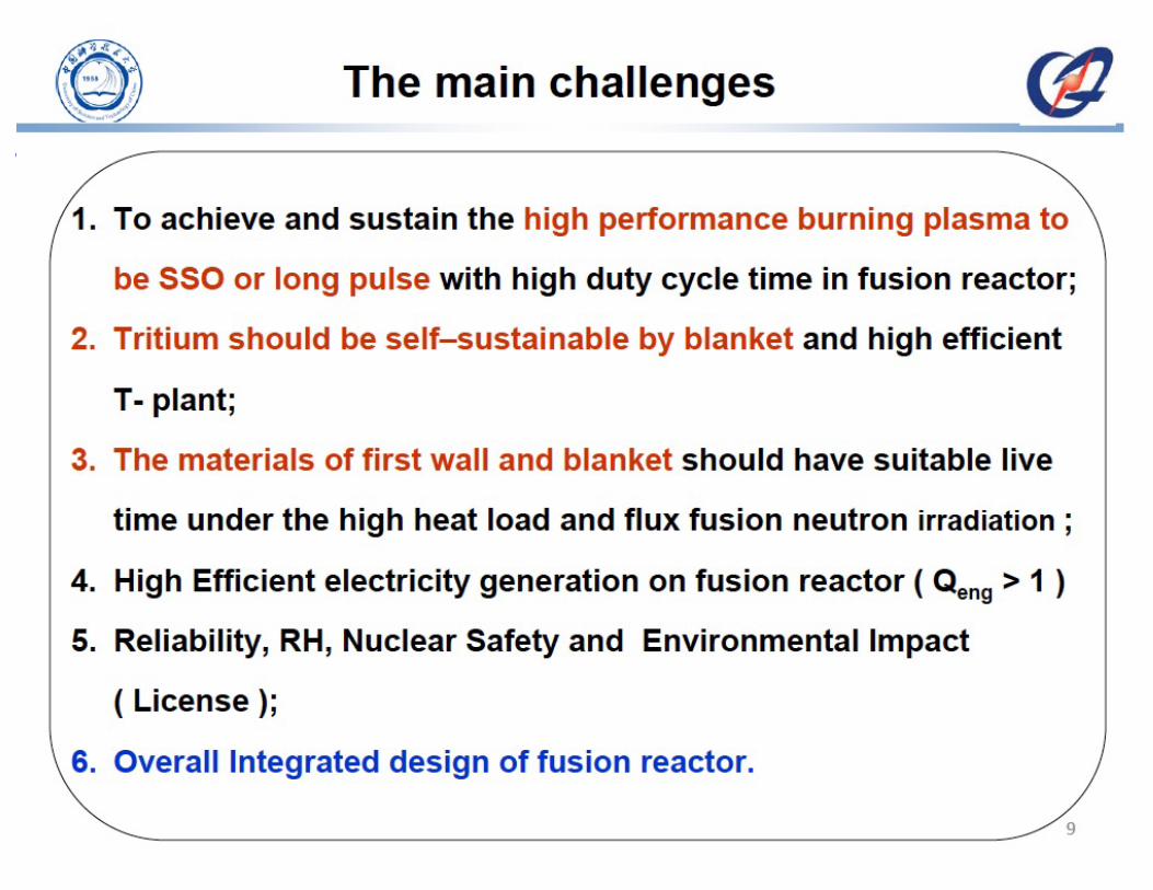
Progress towards fusion energy production
Ref: Greenwald Report, DOE-SC 2007

Overview of Plasma-Material Interactions

BD Wirth, K Nordlund, DG Whyte, and D Xu, MRS Bulletin, 36, 2011
Plasma-Material Interface (PMI) includes plasma physics, materials science, atomic physics…

https://www.euro-fusion.org/jet/
Plasma-materials interactions are one of the key challenges remaining for fusion energy
JET

Outline of Talk
• What is required beyond ITER to get to fusion energy?
• What PMI-related issues emerge from this focus?
• What activities are underway?• What additional efforts are needed?

Outline of Talk
• What is required beyond ITER to get to fusion energy?
• What PMI-related issues emerge from this focus?
• What activities are underway?• What additional efforts are needed?

We are far away from long-duration reactor regime
Kikuchi, Springer 2015
Reactor Regime


PMI Affects
ALL of TheseIssues

Plasma-Material Interactions emphasized as a critical area in several community-generated reports
• US – Research Needs for Magnetic Fusion Sciences, Report of the Research Needs Workshop (ReNeW) : (2009)
• US – FESAC Report on Strategic Planning : (2014)
• EU – A roadmap to the realization of fusion energy : (2014)
• Japan - Report by the Joint-Core Team for the Establishment of Technology Bases Required for the Development of a Demonstration Fusion Reactor : (2014)

Outline of Talk
• What is required beyond ITER to get to fusion energy?
• What PMI-related issues emerge from this focus?
• What activities are underway?• What additional efforts are needed?

PMI Issue Reactor Impact Research Need
Divertor particle & power handling
Dissipate divertorthermal loads ,density control
Edge/SOL transport physics; advanced divertors, transient control
PMI Impact on Confinement
Maintain core plasma performance
Long pulse (1000s seconds) tokamak w/ CFETR relevant wall conditions
Surface Morphology Evolution
Loss of performance at high heat flux; dust generation
Understand mechanisms & manage/avoiddeleterious conditions
Helium Accumulation Effect on D/T Retention, Material performance
In-situ real-time diagnostic for He , D content;
Fuel RetentionProbability ~10-6-10-7
TBR>1 In-situ real-time D, T profiles over <10microns;also need He profiles since He affects retention
Surface Erosion <~1mm/year requires Ynet<10-5
Wall & DivertorReliability & Lifetime
In-situ diagnostics Sensitive to ~100’s nm over 10micron dynamic range
Material Migration & Mixed Material Formation
Minimize & Predictevolution of mixed materials
2D SOL Plasma Flows; in-situ mixed material diagnostics
Rad-damage & Transmutation Effects
New (Degraded?) Materials Properties
Neutron surrogates; neutron irradiation; studies of In-situ retention, material properties
Increasing Timescale

Outline of Talk
• What is required beyond ITER to get to fusion energy?
• What PMI-related issues emerge from this focus?
• What activities are underway?• What additional efforts are needed?

PMI Issue Reactor Impact Research Need
Divertor particle & power handling
Dissipate divertorthermal loads ,density control
Edge/SOL transport physics; advanced divertors, transient effects & control
PMI Impact on Confinement
Maintain core plasma performance
Long pulse (1000s seconds) tokamak w/ CFETR relevant wall conditions
Surface Morphology Evolution
Loss of performance at high heat flux; dust generation
Understand mechanisms & manage/avoiddeleterious conditions
Helium Accumulation Effect on D/T Retention, Material performance
In-situ real-time diagnostic for He , D content;
Fuel RetentionProbability ~10-6-10-7
TBR>1 In-situ real-time D, T profiles over <10microns;also need He profiles since He affects retention
Surface Erosion <~1mm/year requires Ynet<10-5
Wall & DivertorReliability & Lifetime
In-situ diagnostics Sensitive to ~100’s nm over 10micron dynamic range
Material Migration & Mixed Material Formation
Minimize & Predictevolution of mixed materials
2D SOL Plasma Flows; in-situ mixed material diagnostics
Rad-damage & Transmutation Effects
New (Degraded?) Materials Properties
Neutron surrogates; neutron irradiation; studies of In-situ retention, material properties
Increasing Timescale

Divertor heat loads force extreme divertor target designs
Ihli et al, Fus. Eng. Design (2005)
Kukushkin et al JNM 2013

Divertor heat loads force extreme divertor target designs
Ihli et al, Fus. Eng. Design (2005)
Kukushkin et al JNM 2013
With qpeak10 MW/m2
few mm ArmorTinlet=600 CToutlet=680 CTsurf=1200-1500 C

PMI Challenge: Divertor Particle & Heat Loads
• Divertor target must be thin– For qdiv~10MW/m2 ΔT~100
deg-K/mm
• Annual divertor target particle fluence ~1031/m2
• If allow 1mm erosion/yr– NW~6x1028 atoms/m3
– Area density/mm~6x1025/m2
• Allowable net yield Ynet ~ 6x10⁻⁶

PMI Issue Reactor Impact Research Need
Divertor particle & power handling
Dissipate divertorthermal loads ,density control
Edge/SOL transport physics; advanced divertors, transient control
PMI Impact on Confinement
Maintain core plasma performance
Long pulse (1000s seconds) tokamak w/ CFETR relevant wall conditions
Surface Morphology Evolution
Loss of performance at high heat flux; dust generation
Understand mechanisms & manage/avoiddeleterious conditions
Helium Accumulation Effect on D/T Retention, Material performance
In-situ real-time diagnostic for He , D content;
Fuel RetentionProbability ~10-6-10-7
TBR>1 In-situ real-time D, T profiles over <10microns;also need He profiles since He affects retention
Surface Erosion <~1mm/year requires Ynet<10-5
Wall & DivertorReliability & Lifetime
In-situ diagnostics Sensitive to ~100’s nm over 10micron dynamic range
Material Migration & Mixed Material Formation
Minimize & Predictevolution of mixed materials
2D SOL Plasma Flows; in-situ mixed material diagnostics
Rad-damage & Transmutation Effects
New (Degraded?) Materials Properties
Neutron surrogates; neutron irradiation; studies of In-situ retention, material properties
Increasing Timescale

Achieved W divertor erosion rate is too high
Parameter ASDEX-UG1 ALCATOR C-Mod2 Reactor
Exposure time (sec) 2600 3200 3x10⁷
Projected or allowable divertortarget erosion rate (mm/year)
3.6 0.8 1
Measured or allowable W atom erosion/m2
1.5x10²² 1.4x10²¹ 6x1025
Total ion fluence/m2 6x1025 2x1025 3x1031
Effective yield 2.5x10⁻⁴ 7x10⁻⁵ 2x10⁻⁶
Need to reduce Yeff by 30-100xèNeed low Te and/or lower ion flux at target è Advanced Divertor?

Divertor challenge is multifaceted
1. Divertor plate heat flux– Technological limits of ~ 10 MW/m2 , perhaps less at much higher neutron
fluence than ITER
2. Helium pumping– In simulations, degrades very rapidly with power and lower density
3. Plasma erosion of the plate/plasma impurities– High plasma plate temperature/low density greatly increases
sputtering/reduces prompt redeposition
4. Divertor survival of disruptions/ELMs & other transients
Need integrated solution for post-ITER step (CFETR, …)

Research Need: Advanced Divertor
Flux Expansion/Snowflake Super-X Divertor
Kotschenreuther, ReNeW Presentation

PMI Issue Reactor Impact Research Need
Divertor particle & power handling
Dissipate divertor thermal loads ,density control
Edge/SOL transport physics; advanced divertors, transient control
PMI Impact on Confinement
Maintain core plasma performance
Long pulse (1000s seconds) tokamakw/ CFETR relevant wall conditions
Surface Morphology Evolution
Loss of performance at high heat flux; dust generation
Understand mechanisms & manage/avoid deleterious conditions
Helium Accumulation Effect on D/T Retention, Material performance
In-situ real-time diagnostic for He , D content;
Fuel RetentionProbability ~10-6-10-7
TBR>1 In-situ real-time D, T profiles over <10microns;also need He profiles since He affects retention
Surface Erosion <~1mm/year requires Ynet<10-
5
Wall & Divertor Reliability & Lifetime
In-situ diagnostics Sensitive to ~100’s nm over 10micron dynamic range
Material Migration & Mixed Material Formation
Minimize & Predictevolution of mixed materials
2D SOL Plasma Flows; in-situ mixed material diagnostics
Rad-damage & Transmutation Effects
New (Degraded?) Materials Properties
Neutron surrogates; neutron irradiation; studies of In-situ retention, material properties
Increasing Timescale

PMI Challenge: Core-wall integration
Buerskins et al, PPCF 2013 Maggi et al, NF 2015
Wall material choice impacts core plasma viapoorly understood mechanisms…need toUnderstand & predict
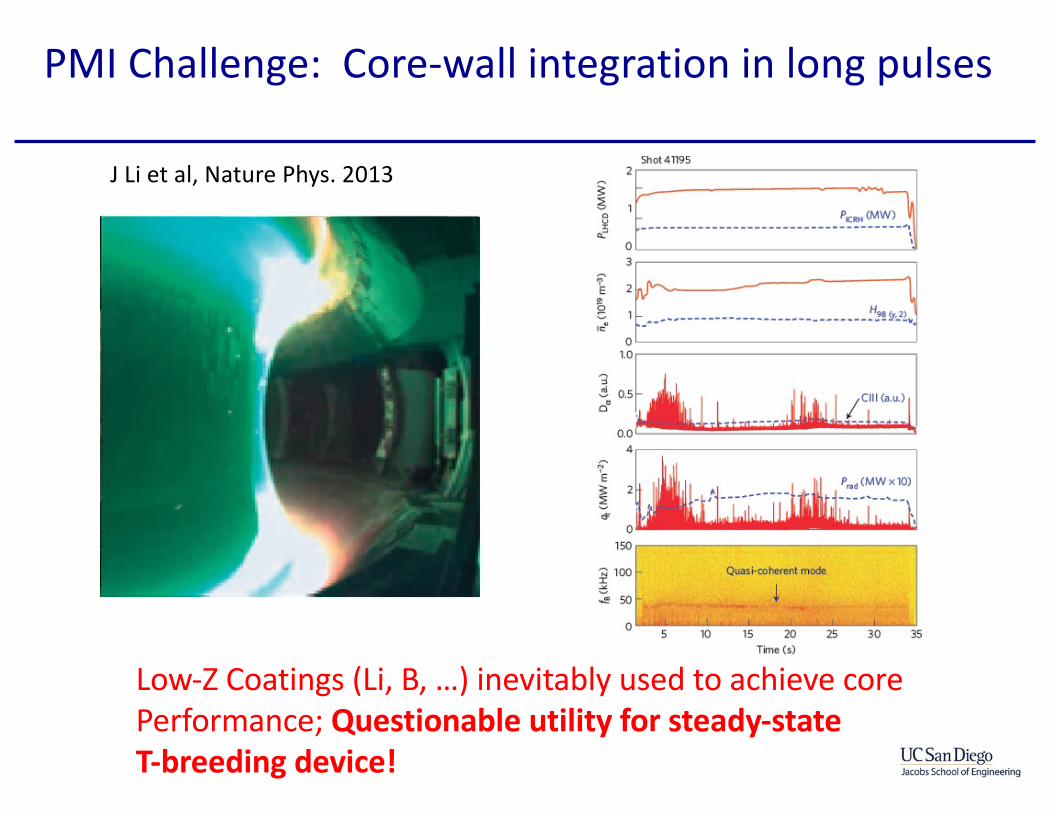
PMI Challenge: Core-wall integration in long pulses
J Li et al, Nature Phys. 2013
Low-Z Coatings (Li, B, …) inevitably used to achieve core Performance; Questionable utility for steady-state T-breeding device!

Research Need:
• Why do low-Z coatings have impact on core plasma performance– Neutral recyling effect?– On Pedestal Fueling?– On Flow Shear?– Something else?
• How to achieve good core performance w/o low-Z coating?
• If not, can low-Z coating be made compatible with requirements of TBR>1, T-inventory control?

PMI Issue Reactor Impact Research Need
Divertor particle & power handling
Dissipate divertor thermal loads ,density control
Edge/SOL transport physics; advanced divertors, transient control
PMI Impact on Confinement
Maintain core plasma performance
Long pulse (1000s seconds) tokamakw/ CFETR relevant wall conditions
Surface Morphology Evolution
Loss of performance at high heat flux; dust generation
Understand mechanisms & manage/avoid deleterious conditions
Helium Accumulation Effect on D/T Retention, Material performance
In-situ real-time diagnostic for He , D content;
Fuel RetentionProbability ~10-6-10-7
TBR>1 In-situ real-time D, T profiles over <10microns;also need He profiles since He affects retention
Surface Erosion <~1mm/year requires Ynet<10-
5
Wall & Divertor Reliability & Lifetime
In-situ diagnostics Sensitive to ~100’s nm over 10micron dynamic range
Material Migration & Mixed Material Formation
Minimize & Predictevolution of mixed materials
2D SOL Plasma Flows; in-situ mixed material diagnostics
Rad-damage & Transmutation Effects
New (Degraded?) Materials Properties
Neutron surrogates; neutron irradiation; studies of In-situ retention, material properties
Increasing Timescale

Linear plasma devices simulate many aspects of fusion PMI science
ITER/tokamak geometry PISCES/linear device geometry

The PISCES-B facility at UCSD
• PISCES-B is located in an air-tight enclosure to allow investigation of Be
• PISCES-A is located outside the Be enclosure to allow easier non-Be investigations and to develop diagnostics for PISCES-B
• The PISCES Program routinely hosts visitors from Japan, EU, China as well as other US Fusion Laboratories

Schematic view
P-B experiments simulateBe erosion from ITER wall,subsequent sol transport and interaction with W bafflesas well as investigation of codeposited materialsusing witness plates

Lab studies give comprehensive plasma, target and impurity diagnostics.
• Plasma impurity concentration – calibrated spectroscopy– magnetically shielded RGA– material surface analysis – LIBS surface contamination
• Erosion yield– weight loss– calibrated spectroscopy– full 3-D modeling
• Ion flux by target bias current and probe measurements
• Sample temperature by IR pyrometers and thermocouples
0
5E+11
1E+12
0 5 10 15axial distance from target (cm)
elec
tron
den
sity
(cm
-3)
0
1
Mac
h nu
mbe
r
He I line ratios
He I absolute intensity
Parallel theory: normalized to probe
Parallel theory: Mach
probe
Plasma density is measured by a reciprocating Langmuir probe, He line ratios, absolute He line intensity and compared to parallel sheath theory.

Laser
Thermal transient (e.g. ELMs) effects on W surfaces
34
Laser heating
• Nd:YAG 1064 nm laser • <2 GW/m2 of absorbed
power density • Pulse width 1 to 10 ms
• Ncycles = 100
2 color pyrometer
Square
Negative ramp
Triangle
Positive ramp
Laser pulse shape canbe controlled. Fourshapes were investigated.

Damage depends on heat pulse shape
35
Tpeak (K)22802600 2780 3130
Pulse shapeSquareNegative RampTrianglePositive Ramp
Square Neg Ramp
Triangle Pos Ramp
100 laser pulses21-56 21-66
21-57 21-67
Tungsten Tmelt = 3695 K, absolute intensity to pyrometeris used to compare surface temperaturedue to different pulse shapes(underestimates temperature)

Damage correlated w peak surface temperature
Melting
It is important to accuratelypredict and model ELMshapes in ITER to understandthe response of the tungstendivertor plates to repetitivethermal cycling.
100 laser pulses

Plasma-implanted D also affects W surface damage
F = 5x10²²/m2
F = 5x10²³/m2
F = 2x1024/m2
Fluence to surface before laser pulse varied
Absorbed Energy Impact~45 MJ/m2 s1/2
(RW (l=1064nm) ~ 70%)
Vbias= -125VG=2x10²²/m2-sec
Te=11eVne=2x1024/m3
Ts ~ 50°C
SAM
PLE
(from K. Umstadter et al., NF 51(2011)053014)

W Temperature Influences PMI Effects
NAGDIS-II: He plasmaD. Nishijima et al. JNM (2004) 329-333 1029• Surface morphology • Shallow depth• Micro-scale
PISCES-A: D2-He plasmaM. Miyamoto et al. NF (2009) 065035600 K, 1000 s, 2.0x1024 He+/m2, 55 eV He+
• Little morphology• Occasional blisters
(b) Under focused (c) Over focused
10nm
10nm
(a) Bright field image (under focused image)
PISCES-B: pure He plasmaM.J. Baldwin et al, NF 48 (2008) 035001
1200 K, 4290 s, 2x1026 He+/m2, 25 eV He+
NAGDIS-II: pure He plasmaN. Ohno et al., in IAEA-TM, Vienna, 20061250 K, 36000 s, 3.5x1027 He+/m2, 11 eV He+
100 nm (VPS W on C) (TEM)
~ 600 - 700 K > 2000 K~ 900 – 1900 K
• Surface morphology • Evolving surface• Nano-scale ‘fuzz’

Fuzz growth consumes W bulk
22000 s, 1120 K60 eV He+
PISCES-Bpure He plasma
~50 ITER shots~6g m-2 (fuzz)
9000 s, 1120 K60 eV He+
PISCES-Bpure He plasma
~20 ITER shots~3g m-2 (fuzz)
2000 s, 1120 K60 eV He+
PISCES-Bpure He plasma
~4 ITER shots~2g m-2 (fuzz) RN
061
5200
7
RN 0
9272
005
RN 0
6182
007
EDX reveals indications of plasma interaction only with top-most fuzzstructures (A). Interface between fuzz and bulk (B) shows no sign of plasma interaction.Fuzz forms from growth, not redeposition. No mass change to samples.

Analytic model captures basic physics
Fuzz
Thic
knes
s
Ion Fluence

PMI Issue Reactor Impact Research Need
Divertor particle & power handling
Dissipate divertor thermal loads ,density control
Edge/SOL transport physics; advanced divertors, transient control
PMI Impact on Confinement
Maintain core plasma performance
Long pulse (1000s seconds) tokamakw/ CFETR relevant wall conditions
Surface Morphology Evolution
Loss of performance at high heat flux; dust generation
Understand mechanisms & manage/avoid deleterious conditions
Helium Accumulation Effect on D/T Retention, Material performance
In-situ real-time diagnostic for He , D content;
Fuel RetentionProbability ~10-6-10-7
TBR>1 In-situ real-time D, T profiles over <10microns;also need He profiles since He affects retention
Surface Erosion <~1mm/year requires Ynet<10-
5
Wall & Divertor Reliability & Lifetime
In-situ diagnostics Sensitive to ~100’s nm over 10micron dynamic range
Material Migration & Mixed Material Formation
Minimize & Predictevolution of mixed materials
2D SOL Plasma Flows; in-situ mixed material diagnostics
Rad-damage & Transmutation Effects
New (Degraded?) Materials Properties
Neutron surrogates; neutron irradiation; studies of In-situ retention, material properties
Increasing Timescale

Near surface He nano-bubbles form in W
[from M. Miyamoto et al., JNM 415(2011)S657]
300ºC 500ºC

These He bubbles act as a diffusion barrier to D
(D-0.25He) Ts= 473 K, Eion= 50 eV (D2) Ts= 473 K, Eion= 50 eV, FD+ = 5-8 x1026 m-2
Single step (D, He) exposure
---
(He) Ts= 473 K, Eion= ~30-50 eVTwo step, He pretreat, D plasma exposure
Mixed D2-He compared to pure D2 Low/High flux He prior to D2, compared
[Miyamoto et al.,NF 49 (2009)]
[Baldwin et al.,NF (2011).
Bubble network provides ‘return pathways’ to PMI surface
interrupting D migration to bulk.
Hebubbles
Nobubbles

3ω method
Thermal Conductivity Measurement of Affected Zone
3ω Au heater
1 2
3 4
Insulation layer(SiO2 or Al2O3 )
Irradiated W layerW substrate
Au heater
1 2
3 4
I(1ω)
• Apply I(ω)• T oscillates at 2ω by Joule heating (Q = I2R)• R oscillates at 2ω (R=Ro+αT)• Can measure T rise from V(3ω)• V3ω = I(ω)R(2ω)
V(3ω)

Cui, Chen, Tynan et al, J Nuc Matl 2017
• κ of plasma-irradiated W (0.7±0.2 W.m-1K-1) is much lower than that of pristine W, presumably due to the defects formed during the irradiation. •Between 300 and 500 K, κ of the plasma-irradiated W is independent of the temperature, also indicating that the electron scattering is dominated by the defects rather than phonon.
M. Miyamoto et al., JNM 415 (2011) S657
300 s 2000 s
Reduced Thermal Conductivity of Nanobubble layer in W

PMI Issue Reactor Impact Research Need
Divertor particle & power handling
Dissipate divertor thermal loads ,density control
Edge/SOL transport physics; advanced divertors, transient control
PMI Impact on Confinement
Maintain core plasma performance
Long pulse (1000s seconds) tokamakw/ CFETR relevant wall conditions
Surface Morphology Evolution
Loss of performance at high heat flux; dust generation
Understand mechanisms & manage/avoid deleterious conditions
Helium Accumulation Effect on D/T Retention, Material performance
In-situ real-time diagnostic for He , D content;
Fuel RetentionProbability ~10-6-10-7
TBR>1 In-situ real-time D, T profiles over <10microns;also need He profiles since He affects retention
Surface Erosion <~1mm/year requires Ynet<10-
5
Wall & Divertor Reliability & Lifetime
In-situ diagnostics Sensitive to ~100’s nm over 10micron dynamic range
Material Migration & Mixed Material Formation
Minimize & Predictevolution of mixed materials
2D SOL Plasma Flows; in-situ mixed material diagnostics
Rad-damage & Transmutation Effects
New (Degraded?) Materials Properties
Neutron surrogates; neutron irradiation; studies of In-situ retention, material properties
Increasing Timescale

Radiation damage processes impact retentionMD Simulation of displacement cascade relaxation (Wirth, private comm.)
• Multiple displacement events create interstitial/vacancy pairs (Frenkel pairs)
• These have deep (>1eV) trap energies and provide sites for trapping D, T, He
• Can use MeV ion beams to replicate some aspects of this physics

D retention in displacement-damaged W
1) Induce Damage w/Heavy Ion Beams
2) Implant D in Linear Plasma Device
3) Measure D profile, content

Wavenumber spectrum of defect sizes in radiation-damaged W
UCSD-LANL-SLAC Collaboration
P. Sun, P. Heimann, Tynan et al, J Nuc Matl’s 2018
XRD Differential scattering cross-section vs defect wavenumber
SSRL

10-50 Angstrom dislocation loops dominant in ion-beam damaged W
Sun, JNM 2018

These defects trap plasma-implanted D
Barton, NF 2016
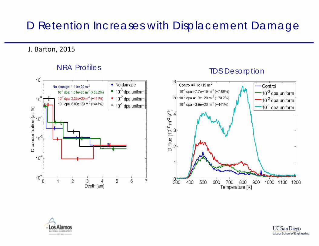
D Retention Increases with Displacement Damage
NRA Profiles TDS Desorption
J. Barton, 2015

These defects can impact T self-sufficiency…
Edge/SOLCore
Edge/SOL
Wall
!mTburn
!MT
inj
!MT
wall (1− R) !MT
wall
Tritium migratingInto wall
Tritium injectedinto plasma
T burnup probability, pburn~0.05
Fueling efficiency, ηfuel~20-30%
Mass balance at wall:
!MT
inj = !mTburn + (1− R) !MT
wall
Mass balance –core plasma:
pburnη fuel!MT
inj = !mTburn
Rate of T inventory build-up:
Δ !mT = (TBR −1) !mTburn
Tynan, Nuc Matls & Energy 2017

PMI Challenge: TBR>1 Imposes severe retention constraint
Edge/SOLCore
Edge/SOL
Wall
!mTburn
!MT
inj
!MT
wall (1− R) !MT
wall
Tritium migratingInto wall
Tritium injectedinto plasma
To avoid impact on TBR, probabilityof trapping T in wall,
ptrap= !MT
trap / !MTwall
ptrap << (TBR −1)(1− R)pburnη fuel
1− pburnη fuel
with TBR ~ 1.05 R ~ 0.99 − 0.999
ptrap <<10−6 −10−7
Tynan, Nuc Matls & Energy 2017

PMI Challenge: In-vessel T Inventory Control
Particle Flux Into Divertor: ~1024/m2-sec
Annual T fluence into divertor: 300 Tonnes-T/yearMaximum allowable mobilizablein-vessel T inventory: O(1kG)
Maximum allowable T retention probability: 3x10⁻⁶
B2-Eirene Simulations, Kikushkin

PMI w/ Radiation damage could limit T self-sufficiency
• He can play a beneficial role, but effect is known to be less efficient in damaged W.
• Sequential damage / PMI on W requires larger fluence ‘cost’.
• Simultaneous plasma-displacement damage effects unknown
• DT fusion energy fundamentally relies on T self-sufficiency, TBR > 1.
• TBR > 1 requires retention probability in FW materials below 10-6.
• In PISCES, D in W retained frac. at 643 K reaches ~10-6 in ~1 week FW fluence.
• At 900 K, <1 h.
Tynan Nuc Matls & Energy 2017, Doerner et al JNM 2019
900 K data*

Control
0.5 K/s ramp rate
1024 D+/cm2
M. Simmonds, 2015
Annealing at high temperature partially heals displacement damage effects in plasma-facing armor materials
RETENTION CAN RECOVER W/ HIGH TEMPERATURE EXPSOSURES

S. Cui, R. Chen et al, J Nuc Matl’s 2018.
Annealing at high temperature partially heals displacement damage effects in plasma-facing armor materials
1E-3 0.01 0.1 1
50
100
150
200
250 Irrad. 300K (Cu ion) Irrad. 573K (Cu ion) Irrad. 773K (Cu ion) Irrad. 1000K (Cu ion) Irrad. 1243K (Cu ion) Irrad. 300K (W ion) Irrad. 1000K(W ion)
Ther
mal
con
duct
ivity
[W/m
-K]
DPA
Pristine W
THERMAL CONDUCTIVITY CAN RECOVER W/ HIGH TEMPERATURE EXPSOSURES

Outline of Talk
• What is required beyond ITER to get to fusion energy?
• What PMI-related issues emerge from this focus?
• What activities are underway?• What additional efforts are needed?

Many PMI issues to study in lab-scale experiments
PMI Issue Science Question Possible Approach
Material Erosion How does high particle flux affect erosion rate?
Implanted depth markers & Ion-beam NRA; Plasma spectroscopy
Material Redeposition How quickly is material being redeposited, and what type of mixed materials are formed?
Ion-beam NRA, LIBS, Plasma Spectroscopy & 2D imaging
Fuel retention in D, D-T, and D-T/He Plasmas
Is D/T retetion low enough for TBR>1?
Ion-beam Rad-damage, NRA, LIBS, Ex-situ TDS
Rad-damage effects on PMI Are there synergistic PMI/Rad-damage effects? Effects on retention? He effects?
Combined plasma/ion beamstudies using He & Heavy Ions; GIXRD
Managing divertor heat flux How do injected divertorimpurities affect material surfaces?
Divertor simulator w/ PMI capabilities

Some critical PMI issues require confinement expts
• Adequate divertor & FW component lifetime– Control plasma erosion rate via divertor plasma physics
(radiative divertor, Super-X, Snowflake, etc…)
• Redeposition, material migration & Fuel retention– Tritium inventory & Closing Fuel Cycle, Safety
• High Performance (Q>>1) Long-pulse (days to weeks) Plasma– Integrate divertor solution w/ core plasma regime
• Demo Adequate reliability, maintainability