Embed Size (px)
Citation preview

Effect of textiles structural parameters on surgical healing; a
case study
Ali Marwa A Spinning and Weaving Engineering Department, Textile Research Division,
National Research Centre, Dokki, Giza, Egypt.
E-mail: [email protected]
Abstract. Medical Textiles is one of the most rapidly expanding sectors in the
technical textile market. The huge growth of medical textiles applications was over the
last 12 years. “Biomedical Textiles” is a subcategory of medical textiles that narrows
the field down to those applications that are intended for active tissue contact, tissue
regeneration or surgical implantation. Since the mid-1960s, the current wave of usage
is coming as a result of new fibers and new technologies for textile materials
construction. “Biotextiles” term include structures composed of textile fibers designed
for use in specific biological environments. Medical Textile field was utilizing
different materials, textile techniques and structures to provide new medical products
with high functionality in the markets. There are other processes that are associated
with textiles in terms of the various treatments and finishing. The aim of this article is
to draw attention to the medical field in each of Vitro and Vivo trend, and its relation
with textile structural parameters, with regard to the fiber material, production
techniques, and fabric structures. Also, it is focusing on some cases studies which
were applied in our research which produced with different textile parameters. Finally;
an overview is presented about modern and innovative applications of the medical
textiles.
1- Introduction
The major challenges in the field of medical textiles are summarized in many items like understanding
the relationship between the structure-property and the novel textile products, tissue engineering
research, scalable and multidisciplinary cooperation [1].
The consumption of Medical Textiles worldwide was 1.5 million tons in 2000 and is growing at an
annual rate of 4.6%. The field of medical textiles is not only included traditional materials, fabric
structures, and manufacturing techniques but also includes all the processes that are associated with
textile in terms of the various treatments, finishing and innovative new materials (see figure1) [2-4].
Figure 1. Procedures for Access to Medical Textiles.
Polymers Fibers Yarns Fabrics Medical Textile Products
Woven, Knitted, Nonwoven, Braided
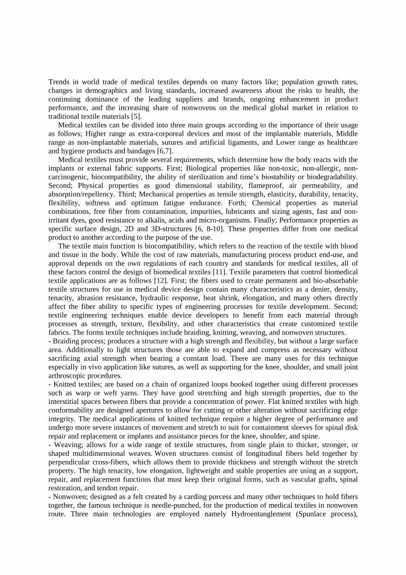
Trends in world trade of medical textiles depends on many factors like; population growth rates,
changes in demographics and living standards, increased awareness about the risks to health, the
continuing dominance of the leading suppliers and brands, ongoing enhancement in product
performance, and the increasing share of nonwovens on the medical global market in relation to
traditional textile materials [5].
Medical textiles can be divided into three main groups according to the importance of their usage
as follows; Higher range as extra-corporeal devices and most of the implantable materials, Middle
range as non-implantable materials, sutures and artificial ligaments, and Lower range as healthcare
and hygiene products and bandages [6,7].
Medical textiles must provide several requirements, which determine how the body reacts with the
implants or external fabric supports. First; Biological properties like non-toxic, non-allergic, non-
carcinogenic, biocompatibility, the ability of sterilization and time’s biostability or biodegradability.
Second; Physical properties as good dimensional stability, flameproof, air permeability, and
absorption/repellency. Third; Mechanical properties as tensile strength, elasticity, durability, tenacity,
flexibility, softness and optimum fatigue endurance. Forth; Chemical properties as material
combinations, free fiber from contamination, impurities, lubricants and sizing agents, fast and non-
irritant dyes, good resistance to alkalis, acids and micro-organisms. Finally; Performance properties as
specific surface design, 2D and 3D-structures [6, 8-10]. These properties differ from one medical
product to another according to the purpose of the use.
The textile main function is biocompatibility, which refers to the reaction of the textile with blood
and tissue in the body. While the cost of raw materials, manufacturing process product end-use, and
approval depends on the own regulations of each country and standards for medical textiles, all of
these factors control the design of biomedical textiles [11]. Textile parameters that control biomedical
textile applications are as follows [12]. First; the fibers used to create permanent and bio-absorbable
textile structures for use in medical device design contain many characteristics as a denier, density,
tenacity, abrasion resistance, hydraulic response, heat shrink, elongation, and many others directly
affect the fiber ability to specific types of engineering processes for textile development. Second;
textile engineering techniques enable device developers to benefit from each material through
processes as strength, texture, flexibility, and other characteristics that create customized textile
fabrics. The forms textile techniques include braiding, knitting, weaving, and nonwoven structures.
- Braiding process; produces a structure with a high strength and flexibility, but without a large surface
area. Additionally to light structures those are able to expand and compress as necessary without
sacrificing axial strength when bearing a constant load. There are many uses for this technique
especially in vivo application like sutures, as well as supporting for the knee, shoulder, and small joint
arthroscopic procedures.
- Knitted textiles; are based on a chain of organized loops hooked together using different processes
such as warp or weft yarns. They have good stretching and high strength properties, due to the
interstitial spaces between fibers that provide a concentration of power. Flat knitted textiles with high
conformability are designed apertures to allow for cutting or other alteration without sacrificing edge
integrity. The medical applications of knitted technique require a higher degree of performance and
undergo more severe instances of movement and stretch to suit for containment sleeves for spinal disk
repair and replacement or implants and assistance pieces for the knee, shoulder, and spine.
- Weaving; allows for a wide range of textile structures, from single plain to thicker, stronger, or
shaped multidimensional weaves. Woven structures consist of longitudinal fibers held together by
perpendicular cross-fibers, which allows them to provide thickness and strength without the stretch
property. The high tenacity, low elongation, lightweight and stable properties are using as a support,
repair, and replacement functions that must keep their original forms, such as vascular grafts, spinal
restoration, and tendon repair.
- Nonwoven; designed as a felt created by a carding porcess and many other techniques to hold fibers
together, the famous technique is needle-punched, for the production of medical textiles in nonwoven
route. Three main technologies are employed namely Hydroentanglement (Spunlace process),

Spunbonding and Melt-blow process [13,14]. Nonwoven structures provide greater surface area than
most other textiles techniques, as well as a unique 3D architecture. The construction of nonwovens
helps to support cellular ingrowth and proliferation for repair functions with carefully designed layers
of entangled fibers and extensive pore size.
Nonwovens are used extensively in the medical field because of relatively high absorption abilities
and allowing sterilization of the fabric at high temperatures. Nonwoven materials with improved
finishes such as liquid repellent, virus proof and bacterial resistance have been developed for
applications such as surgical masks, gowns, drapes, baby diaper/adult incontinence products, wipes,
bacteria–proof cloth...etc (figure2). In general, cellulosic fibers are preferred for their high strength,
pliability, plastic deformation resistance and water insolubility [13,15].
Third; twist and Shape in order to totally take advantage of the characteristics of each manufacturing
technique, structures and processes that can maximize performance to fixed specifications which
contain texturing, twisting, plying, and precision cutting techniques such as a die, laser, ultrasonic, and
staple cutting. Shaping is a finishing method for molding and allows for different geometries shapes
such as tubes, cones, disks, and cylinders for implantation, while blending between two dissimilar
materials into a single structure, lead to creating a heterogeneous material to weaving [12].
2- Materials and methods
Fibers with different materials are used in a variety of applications depending on the characteristics
required, as ineffective repairs of the body like wound closure with sutures or replacements surgery.
Fibers in the medical field include natural fibers like; cotton, wool, silk …etc, and synthetic fibers.
All bioabsorbable fibers are not created equal [6]. Synthetic polymers used widely, they can be
divided into permanent fibers e.g. polyamide, polyester, polyethylene, polypropylene,
polytetrafluoroethylene, polyurethane and carbon fibers which is used for its strength in artificial
ligaments and for its lubricity in orthopaedic cushioning and biodegradable fibers which are mainly
used in sutures and tissue engineering structures e.g. polycaprolactone, polyglycolic acid and
polylactic acid. As well natural biological fibers like chitin, collagen and alginate fibers [2,11].
Different methods are used to evaluate medical textile product suitability for the application. These
methods include many properties that must be present according to the characteristics of textile, yarn
and fibers like; analysis of fiber components, tenacity, softness, tensile strength, elongation,
absorption, dimensional stability, stiffness, abrasion resistance, antistatic resistance, crease recovery,
air permeability, weight and thickness of fabric, porosity, bursting resistance, antimicrobial resistance
and materials components analysis in case of whether the product is subject to treatments or finishing
before it is set to the final use. Additionally; the biological analysis were applied as clinical
examination, x-ray, sonar, blood analysis, immune analysis and histopathological changes.
Currently, researchers are conducting to know the compatible extent between new materials and
different tissues organs in the body live. This is through the planting of different materials with stem
cells, the follow-up to the changes that occur, and analyzing these changes. This enhances the field of
application of new materials outside the human body (Vitro tissue engineering), whether as an
alternative to the application on animals or the next stage of the animal experimental to make sure the
suitability with the human body. It is considered one of the phases, which passes by the application or
medical product before its adoption and set it in the medical market.
Figure 2. Some applications of nonwoven spunlace technology.

3- Results and discussions
3-1 First case based on nonwoven technique.
This study performed by A. Abou-Okeil et al. It had investigated of wound dressing based on
nonwoven viscose fabrics for raising the healing of tissue [16].
Three types of the nonwoven web were produced with a random distribution of fibers. These webs
differ among themselves according to the blend ratios between materials and weights as (100%
Viscose with weight 45g/m2, 30% Viscose: 70 % polyester with weight 30 g/m
2, and 70% Viscose:30
% polyester with weight 45 g/m2). The three types of webs are treated with a chitosan solution ranging
(0.2 - 0.8%), adding polyvinyl alcohol solution ranging between (2-14 ml), then the webs were sunken
in 30 ml of silver micro granules solution, finally were disposed of extra solution and dried [17]. Small
rabbits are used for applying the experimental surgical and divided them into three groups according
to the factors in the study (figure 3); the first group had used three fabrics without treatment, the
second group had used three fabrics treated using chitosan/polyurethane vinyl alcohol, the third group
had used three fabrics treated using chitosan solution/polyvinyl alcohol with silver nanoparticles.
The results that pointed to the 100% viscose sample without treatment achieved the best
consequences of healing cells, and the body absorbed it completely. Whereas, the best sample after
complete treatment was (30%Viscose:70%polyester) after 21 days from the experimental work [16].
3-2 Second case based on woven technique.
This study about woven technique performed by Inas N. El-Husseiny et al. It had investigated of
surgical management of patellar ligament rupture in dogs using a prosthetic woven fabric [18].
A woven fabric produced using a blend of two biomaterials, polyamide 6.6 for weft yarns and
polyester for warp yarns (50:50) %, with plain structure 1/1. Were used monofilament microfibers for
each of the warp and weft yarns, the yarn count for each material is 40 dtex. All samples were used
raw without treatment. Twelve skeletally mature mongrel dogs with no evidence of clinical signs of
lameness were used in the study. Surgical intervention was performed by primary suturing of the
severed patellar ligament ends by diameter 3mm, and applying a synthetic fabric to act as a supportive
internal splint. Satisfactory results were obtained concerning the tendon healing and the return to limb
normal function without complications (figures 4&5). Continued subsistence from three to six months,
then the death by using merciful dies, in order to carry out biological analysis [18].
Figure 3. Wound healing stages during 21 days.
Figure 5. (A) An experimental case just
surgery, (B) after 180 day’s post operation.
B A
Figure 4. (A) The application of the twisted
synthetic fabric, (B) The lateral view of the stifle.
A B

3-3 Second case based on woven technique.
Another study about woven technique performed by Marwa A. Ali et al. It had investigated of grafting
prop for the stomach and duodenum wall with woven fabrics from different materials and structures
[19,20].
Twelve woven samples were produced and weaved with plain 1\1, basket and leno structures. They
were divided into two categories according to raw materials type; first carbon and glass fiber materials
as a synthetic category, and second cotton and flax fibers as a natural category [19, 20]. Sterilization
for the samples was done by autoclave, and then treated with 2% glutaraldehyde solution as
sterilization immediately before surgery [21]. The surgical experiments were carried out to support
stomach and duodenum in different places as (A) subserosa, (B) all through the gastric wall and (C)
ball through the duodenum wall (figure 6). As a medication for some of the problems that afflict the
stomach and duodenum, which require a surgical intervention as chronic erosive gastric, chronic
gastric ulcer, chronic stress erosion, persons are infected with Zollinger-Ellison syndrome and
perforation in the stomach wall [22]. The experimental study was applied on male dogs, and continued
of subsistence 21 days for experimental animals with notation of clinical observation daily, after the
merciful death of animals was performed biological analysis like X-ray, Blood analysis and
Histopathological changes [19, 20]. The results showed the samples produced from carbon fibers
achieved the high significant healing cells; especially the samples formed using plain 1/1 and leno
structures(figures 7) [19]. The cotton sample with leno structure achieved the best result comparing
with flax samples, whereas the flax samples contains another component such as oil, ash, grease and
pectin (figures 8&9) [20].
4- Recent Medical Applications There are many recent applications in the field of surgical healing. These applications include new products that are used in the body reinforcements and supporting for critical external wounds.
4-1 Absorbable Bidirectional Barbed Suture
This type of suture appeared in 1992, it was made of Polydioxanone and doesn’t need to be removed
and doesn’t require knots to make it suture. So it can be used in cosmetics surgery, dermal tissue
approximation, internal wound closure, and tendon repair (figure10). The specification of the
Figure 6. Transplantation places of woven
fabric on the stomach and duodenum wall.
A
B C
Figure7. Healing tissue (A) carbon fibers, (B)
glass fibers with different structures.
A
B
Figure 9. (A) Stomach with plain 1\1 structure weaved
with cotton, (B) Duodenum with leno structure; (a)
shows the normal gastric mucosa.
a
a
A
a
a
B
Figure 8. (A) External healing, (B)
Internal healing of cotton.
B A
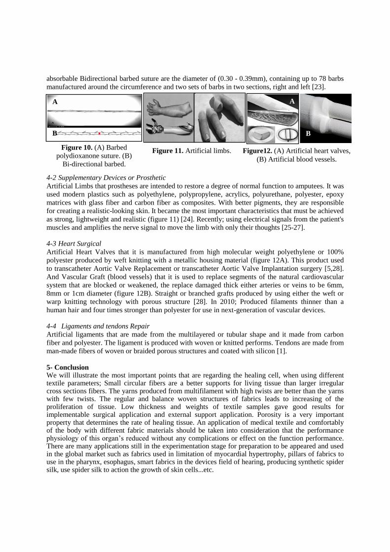
absorbable Bidirectional barbed suture are the diameter of (0.30 - 0.39mm), containing up to 78 barbs
manufactured around the circumference and two sets of barbs in two sections, right and left [23].
4-2 Supplementary Devices or Prosthetic
Artificial Limbs that prostheses are intended to restore a degree of normal function to amputees. It was
used modern plastics such as polyethylene, polypropylene, acrylics, polyurethane, polyester, epoxy
matrices with glass fiber and carbon fiber as composites. With better pigments, they are responsible
for creating a realistic-looking skin. It became the most important characteristics that must be achieved
as strong, lightweight and realistic (figure 11) [24]. Recently; using electrical signals from the patient's
muscles and amplifies the nerve signal to move the limb with only their thoughts [25-27].
4-3 Heart Surgical
Artificial Heart Valves that it is manufactured from high molecular weight polyethylene or 100%
polyester produced by weft knitting with a metallic housing material (figure 12A). This product used
to transcatheter Aortic Valve Replacement or transcatheter Aortic Valve Implantation surgery [5,28].
And Vascular Graft (blood vessels) that it is used to replace segments of the natural cardiovascular
system that are blocked or weakened, the replace damaged thick either arteries or veins to be 6mm,
8mm or 1cm diameter (figure 12B). Straight or branched grafts produced by using either the weft or
warp knitting technology with porous structure [28]. In 2010; Produced filaments thinner than a
human hair and four times stronger than polyester for use in next-generation of vascular devices.
4-4 Ligaments and tendons Repair
Artificial ligaments that are made from the multilayered or tubular shape and it made from carbon
fiber and polyester. The ligament is produced with woven or knitted performs. Tendons are made from
man-made fibers of woven or braided porous structures and coated with silicon [1].
5- Conclusion We will illustrate the most important points that are regarding the healing cell, when using different textile parameters; Small circular fibers are a better supports for living tissue than larger irregular cross sections fibers. The yarns produced from multifilament with high twists are better than the yarns with few twists. The regular and balance woven structures of fabrics leads to increasing of the proliferation of tissue. Low thickness and weights of textile samples gave good results for implementable surgical application and external support application. Porosity is a very important property that determines the rate of healing tissue. An application of medical textile and comfortably of the body with different fabric materials should be taken into consideration that the performance physiology of this organ’s reduced without any complications or effect on the function performance. There are many applications still in the experimentation stage for preparation to be appeared and used in the global market such as fabrics used in limitation of myocardial hypertrophy, pillars of fabrics to use in the pharynx, esophagus, smart fabrics in the devices field of hearing, producing synthetic spider silk, use spider silk to action the growth of skin cells...etc.
Figure 10. (A) Barbed
polydioxanone suture. (B)
Bi-directional barbed.
B
A
Figure 11. Artificial limbs. Figure12. (A) Artificial heart valves,
(B) Artificial blood vessels.
B
A
7- References
[1] Grace S A 2013 GRA - Global Research Analysis. Recent Developments in Medical Textiles
Implantable Devices – An Overview 2 2277 – 8160.
[2] Stephen M W 2014 Textile World Innovation. Biomedical Textiles: A Fast-growing Market.
[3] Robert C 2005 FIBRES & TEXTILES in Eastern Europe. Development of Medical Textile
Market 13.
[4] www.fibre2fashion.com/...article/.../Nonwovens-For-Medical-Textiles.pd
[5] www.wp.tx.ncsu.edu/biomedicaltextiles
[6] www.academia.edu/9791714/Medical_Textiles
[7] www.depart.zzti.edu.cn/foreign/.../Lecture4-TECHNICALTEXTILES-Zhongy.
[8] www.textilelearner.blogspot.com/2012/02/introduction-of-medical-textiles.html
[9] Parveen B K, Subramaniam V and Pradeepa P 2014 International Journal of Current Research.
Non-Implantable Materials in Medical Textiles 6 6120-6123.
[10] www.fibre2fashion.com – fiber fashion news app
[11] www.hw.ac.uk/sbc/BTRC/BTRC/private/Whatare.htm -Textile Innovation
[12] www.mdtmag.com/.../5-key-considerations-working-biomedical-textiles
[13] Chellamani K P, Vignesh Balaji R S and Veerasubramanian D 2013 J. Acad. Indus. Res.
Medical Textiles: The Spunlace process and its application possibilities for hygiene textiles
1 735- 739.
[14] Chinta S K, Landage S M, Abhishek, Sonawane K D and Jalkate C B 2012 Global Journal of
bioscience & Biotechnology (GJBB). Medical Textiles– Application of Essential oil as
Antimicrobial Agent on Nonwoven 1 75-80.
[15] www.nonwovens-industry.com
[16] A Abou-Okeil, sheta A M, A Amr, Marwa A Ali, 2012 Carbohydrate Polymers. Wound
Dressing Based on Nonwoven Viscose Fabrics 90 958-666
[17] Sileikait˙e, A, Prosyˇcevas, I, Puiˇso, J, Juraitis, A, & Guobien˙e, A 2006 Materials Science.
Analysis of silver nanoparticles produced by chemical reduction of silver salt solution 12
287–291.
[18] Inas N El-Husseiny, Ali Marwa A, Ayman A Mostafa and Mahmoud H Elshakankery 2011
Journal of American Science. Surgical Management of Patellar ligament Rupture in Dogs
Using a Prosthetic Woven Fabric: Experimental Study 7 482-490.
[19] Shirazy E H, M M Saad, A. M. Sheta, M El-shakankery, Marwa A Ali, 2010 7th
International
conference of textile research Division, NRC, Cairo, Egypt. Grafting Prop for the Stomach
and Duodenum Wall by woven meshes from Carbon and Glass Fabrics 247-257.
[20] Shirazy E H, M M Saad, A. M. Sheta, M El-shakankery, Ali Marwa A 2014 Journal of the
Textile Association. Supporting with natural meshes of cotton and linen for parts of the
digestive system July-August 118-125.
[21] Bancroft D, Stevens A and Turner R 1996 Theory and Practice of histological Techniques, 4Th
Ed., Churchill, Livingstone Edinburg, London, Melbourne.
[22] Richard W N , Guillermo C C and Nelson C 2003 Hand Book “Small Animal Internal
Medicine”, 3ed
Ed., 30-112.
[23] Philip PD Jr, Martin WK, Nancy LC and Jeffrey CL 2002 Journal of Textile and Apparel,
Technology and Management. Medical Textiles: Application of Absorbable Barbed Bi-
directional Surgical Suture 2 .
[24] www.science.howstuffworks.com/prosthetic-limb2.htm
[25] www.madehow.com/Volume-1/Artificial-Limb.html
[26] www.swicofil.com/biomedical_textiles.html
[27] www.powershow.com/.../Gemma_Downey_What_Is_It_Prosthetic_Techno
[28] https://www.dsm.com/content/dam/dsm/.../DSM-Secant-white-paper.pdf
Evaluation of optical data gained by ARAMIS-measurement of abdominal wall movements for an anisotropic pattern design of stress-adapted hernia meshes produced by embroidery technology
A Breier, L Bittrich, J Hahn, and A Spickenheuer Leibniz-Institut für Polymerforschung Dresden e. V., Institute of Polymer Materials, Department of Composite Materials, Hohe Str. 6, 01069 Dresden, Germany E-mail: [email protected] Abstract. For the sustainable repair of abdominal wall hernia the application of hernia meshes is required. One reason for the relapse of hernia after surgery is seen in an inadequate adaption of the mechanical properties of the mesh to the movements of the abdominal wall. Differences in the stiffness of the mesh and the abdominal tissue cause tension, friction and stress resulting in a deficient tissue response and subsequently in a recurrence of a hernia, preferentially in the marginal area of the mesh. Embroidery technology enables a targeted influence on the mechanical properties of the generated textile structure by a directed thread deposition. Textile parameters like stitch density, alignment and angle can be changed easily and locally in the embroidery pattern to generate a space-resolved mesh with mechanical properties adapted to the requirement of the surrounding tissue. To determine those requirements the movements of the abdominal wall and the resulting distortions need to be known. This study was conducted to gain optical data of the abdominal wall movements by non-invasive ARAMIS-measurement on 39 test persons to estimate direction and value of the major strains.
1. Introduction Abdominal wall hernia describes the expulsion of bowels through an opening in the abdominal wall. The margin tissue of the cracked abdominal wall is unable to recover autonomously and untreated hernia can cause complications such as organic dysfunction, intoxication and necrosis of the particular area. Thus, surgical intervention is indispensable. Due to the variety of causes and occurrence abdominal wall hernia surgery is the most frequently operated surgical intervention worldwide [1]. Suture of the fissure causes tension on the margin tissue and often results in relapse [2]. To restore the function of the abdominal wall reinforcing meshes have to be applied [3]. Although the relapse rate can be lowered the application of alloplastic meshes causes infection, migration, dislocation as well as intraabdominal adherence and fistula [2, 3]. Next to influencing factors such as choice of material or surface characteristics a decisive parameter for triggering malfunction is seen in the structural design of the mesh [3, 4]. The structures are distinguished in heavy and light weight meshes, measured in weight per unit area (g/cm2) and defining a more or less dense porosity. While heavy weight meshes facilitate the generation of scar tissue and imply a higher risk of infection the preferred light weight meshes are often reported on shrinking and wrinkle formation, which can cause pain and discomfort at the implantation site [3, 4]. A further limitation of the commercially available meshes is seen in the mechanical properties not matching the conditions in the abdominal wall [5]. Junge et al. determined elongations of the abdominal wall in a range of 11 % to 32 %, while the probed meshes showed elongations between 4 % to 16 % under the same load [6]. It is assumed, that the motility of the
abdominal wall at the implantation site is limited to such an extent, that the relapse occurs on the margin of the mesh at the transition into the natural tissue [6]. Novel designs of commercially available meshes already showed improved re-establishment of the mechanical function [7] and first approaches of simulating the mechanical processes in the abdominal wall by finite element modelling are made [8, 9, 10]. A considerable issue for the simulation of abdominal wall processes is the compilation of reliable data and only few studies introducing numerical values are available [11, 12].
Meshes for abdominal wall hernia reconstruction are usually fabricated by textile processes, primarily by knitting and warp-knitting but also by weaving or depositing as nonwoven structures [13]. Knitted and warp-knitted structures are generated by loop formation (stitches) and show a feasible porosity, a high elasticity and a predominant anisotropic behavior compared to woven and nonwovens. But knitted meshes tend to unravel when cut and the parameters for influencing the mechanical and anisotropic behavior are limited [13]. A new approach is seen in using embroidery technology for manufacturing meshes with adapted mechanical properties [14]. Embroidery technology can be used for generating dimensionally stable scaffolding structures with defined characteristics for implants and tissue engineering applications [15, 16]. Porosity, mechanical properties or degradability can be adjusted by textile parameters like stitch length, stitch alignment as well as choice of thread size or material [15]. The design of the structures can be performed by the specific punch software EDOpath, primarily developed for light weight construction by Tailored Fiber Placement (TFP) technology, allowing additonally a transfer of finite element method (FEM) data into an embroidery pattern [17].
According to the request for a mesh structure with mechanical behavior adapted to the conditions in the defect area, the idea is to create a structure with reinforcing stiff units in the area of the opening, framed by an elastic unit in the margin area showing a graded transition into the surrounding tissue [14]. The design of the embroidery pattern is to be based on the simulation of the abdominal wall movements. To establish a finite element model for the simulation, data of the human abdominal wall have to be compiled. This study was conducted to gain optical data of the abdominal wall movements by non-invasive ARAMIS-measurement on 39 test persons to estimate direction and value of the major strains.
2. Materials and Methods The abdominal wall of 35 adult test persons (mean age 33 a ± 10 a), divided into 18 male (mean age 30 a ± 7 a) and 17 female (mean age 36 a ± 11 a), and of 4 children (mean age 10 a ± 4 a) divided into 3 boys (mean age 10 a ± 4 a) and one girl (aged 11 a) were prepared with a speckle pattern comprising the front abdominal area from the costal arch to the pelvic bone. This was obtained by a random dot stamp pattern for a 100 mm x 130 mm stamp area, which was designed with 1.5 mm dot diameter and a black-white contrast of 50% (Fig 1A). The stamp was lined with a 40 mm foam material layer to enable smooth movement of the rubber face on the uneven surface of the abdominal wall (Fig 1B, white arrow). Black body paint (Clean Colors, Fa. Farbstark, Stadthagen) was applied on the face with a foamy painting roller as stamping ink. Four to five imprints were performed on the abdominal skin generating a consistent pattern. Voids were filled up manually with a brush (Fig 1C).

Figure 1. Preparation of the test persons: (A) random dot pattern with 1.5 mm dot diameter and a black white contrast of 50 %, (B) stamp 100 cm x 130 cm with the random dot pattern and lined with a 40 mm foam material layer (white arrow) and (C) abdominal wall of a male test person furnished with a dot pattern.
The prepared test persons were arranged in front of the ARAMIS-measurement system (GOM, Germany) (Fig. 2A) composed of two cameras for a three dimensional image acquisition featuring a resolution of 2400 pixels x 1728 pixels (Fig. 2B). Facets were determined with 15 pixels x 12 pixels. Deformations of the facets were measured during six abdominal movements (relaxed (Fig. 3 A, D), semi protruded, protruded (Fig. 3 B, E), semi contracted, contracted (Fig. 3 C, F) and strained). A qualitative evaluation of the major strain was performed using the ARAMIS software (Fig. 3 A, B, C). For further analysis with finite element (FE)-software tools the three dimensional position data of each facet was exported and fitted to a cubic B-spline surface for each deformation step (Fig. 3 D, E, F). A hernia mesh can be connected to the surface for mechanical simulation of stress and strain behavior during dynamic loads by interpolating the deformation states.
Figure 2. ARAMIS measurement system (GOM, Germany: (A) positioning of the test person, (B) measurment equipment with comuputer (left) and camera unit (right) and (C) determined measuring zone (green) on the abdominal wall.
Figure 3. Evaluation of the abdominal wall movements by the ARAMIS software (A, B, C) and exported three dimensional position data fitted to a cubic B-spline (D, E, F) for relaxed (A, D), protruded (B, E) and contracted (C, F) state.
3. Results An optimal dot pattern design and a reproducible application method were specified for optical measurements of human abdominal walls. Talcum was identified as an important additive in the body paint to achieve accurately rimmed dots and thus a distinguishable contrast. The dot pattern had to be

supplemented with some individual spots applied manually with a brush which were used by the ARAMIS software to identify the measuring unit and its movements.
The major strain of each test person’s abdominal wall was qualitatively evaluated. Section planes were cut longitudinal across the abdominal wall and the major strains along these axes could be depicted in diagrams and determined to a percental value for all motion states (Fig. 4). An anisotropic mechanical behavior of the abdominal wall could be demonstrated. A strong variation of the major strain values was observed comparing different test persons of the same sex in one motion state. The minimum value of the major strain was -15 % for male and female test persons, whereas the maximum value was 60 % for male and 50 % for female test persons.
Figure 4. Section planes longitudinal to the abdominal wall (A) and the major strains along these x-axes.
Furthermore, the experimental data were transferred to a FE model. A parametrizable surface was defined to enable individual meshing and simulating the spatial distortion of the abdominal wall. However, the material parameters of the abdominal wall tissues are unknown. So the strain behavior between each deformation state was modelled with the FE software ANSYS by applying arbitrary isotropic material parameters and using the experimentally fitted displacement data at each node. Fig. 5 shows the first principal strain of an analysis with this data.
Figure 5. Contour plot of the first principal strain of the semi contracted state obtained by finite element analysis.

4. Discussion Commonly used hernia meshes display isotropic mechanical and physical properties, while the abdominal wall musculature exhibits an anisotropic mechanical behavior. To prevent hernia mesh failure an adapted structure is required. Embroidery technology enables the manufacturing of anisotropic mesh structures by stress-adapted pattern design. However, the design of stress-adapted patterns requires a comprehensive knowledge of the stress-strain conditions in the abdominal wall and simulating the abdominal wall movements by FEM seems feasible. In this study optical data, gained from abdominal movements of test persons, were applied to determine direction and value of the major strains. But the corresponding stresses are meaningless as long as no realistic material parameters are found.
An approach to fit the anisotropy parameters of the material was made by relaxing the boundary conditions of the model in extended regions within the centre of the model, here by removing the displacement constraints at the corresponding nodes and replacing it by a constant hydrostatic pressure. Comparing the strain distribution of this new simulation to the first simulation result, the fitting parameters can be defined to the anisotropy parameters of the material in the relaxed zone and the magnitude of the hydrostatic pressure. Thus an iterative fitting method will lead to a qualitative material model, which allows at least qualitatively meaningful stress results. These derived FE-models can be used to simulate defects and patching with hernia mesh structures.
5. Conclusion A non-invasive measurement method was established to gain optical data of the abdominal wall during different movements. Therewith, an FE model was developed to design embroidery patterns for mesh structures with an anisotropic mechanical behavior. The compiled data and the derived FE model not only enable the determination of the major stresses, they also comprise the potential to an iterative fitting method resulting in a qualitative material model. Future works will focus on the transfer of these models into embroidery pattern designs and thus to individualized hernia mesh structures.
6. Acknowledgments The authors acknowledge the financial support of the Federal Ministry of Education and Research (AiF-IGF-Project “LoVarMed”, financial support number: 320050).
References [1] Kalaba S, Gerhard E, Winder J S, Pauli E M, Haluck R S and Yang J 2016 Design Strategies
and Applications of Biomaterials and Devices for Hernia Repair Bioact. Mat. 1(1) p 2 - 17. [2] Friedrich M 2008 Wechselwirkung zwischen leichtgewichtigen Herniennetzen aus
Polypropylen verschiedener Hersteller und ausgewählten humanen Zellen, Dissertation Lübeck, Univ. Klinik für Chirurgie.
[3] Schumpelick V, Klosterhalfen B, Müller M et al. 1999 Minimierte Polypropylen-Netze zur präperitonealen Netzplastik (PNP) der Narbenhernie - Eine prospektive randomisierte klinische Studie. Chirurg 70, p 422-30.
[4] Zogbi L, Trindade EN and Trindade M 2013 Comparative study of shrinkage, inflammatory response and fibroplasia in heavyweight and lightweight meshes. Hernia 17(6), p 765-72.
[5] Dietz U 2013 Medizinische Herausforderungen für textile Implantate Fachtagung Polymere Biomaterialien - vom Material zum Gewebe Würzburg.
[6] Junge K, Klinge U, Prescher A et al. 2001 Elasticity of the anterior abdominal wall and impact for reparation of incisional hernias using mesh implants. Hernia 5(3), p 113-8.
[7] Podwojewski F, Otténio M, Beillas P et al. 2013 Mechanical response of animal abdominal walls in vitro: Evaluation of the influence of a hernia defect and a repair with a mesh implanted intraperitoneally Journal of Biomechanics 46 (3), p 561-6.
[8] Tomaszewska A, Lubowiecka I, Szymczak C et al. 2013 Physical and mathematical modelling of implant-fascia system in order to improve laparoscopic repair of ventral hernia Clinical
Biomechanics 28 (7), p 743-51. [9] Justinger C. Shklyar I, Klein P and Schilling M 2011 Developing new strategies in abdominal
wall closure using a virtual mechanical model. The World Journal of Hernia and Abdominal Wall Surgery 15, p 855.
[10] Hernández-Gascóna B, Peñaa E, Melerod H et al. 2011 Mechanical behaviour of synthetic surgical meshes: Finite element simulation of the herniated abdominal wall. Acta Biomaterialia 7(11), p 3905-13.
[11] Cobb WS, Burns JM, Kercher KW, Matthews B, Northon HJ and Heniford T 2005 Normal intraabdominal pressure in healthy adults J Surgical Research 129, 231-5.
[12] Pott PP, Schwarz MLR, Gundling R, Nowak K, Hohenberger P, et al. 2012 Mechanical properties of mesh materials used for hernia repair and soft tissue augmentation. PLoS ONE 7(10), e46978.
[13] Zhu LM, Schuster P, Klinge U 2015 Mesh Implants: An overview of crucial mesh parameters. World Journal of Gastrointestinal Surgery 7 (10), p 226 – 36.
[14] Hahn J, Bittrich L, Breier A, Spickenheuer A 2017 Stress adapted embroidered meshes with a graded pattern design for abdominal wall hernia repair AUTEX Conference (Korfu)
[15] Breier A 2015 Embroidery technology for hard tissue scaffolds. Biomedical Textiles for Orthopaedic and Surgical Applications: Fundamentals, Applications and Tissue Engineering ed Blair T (Woodhead Publishing) p 23–43.
[16] Hahner J, Hinüber C, Breier A, Siebert T, Brünig H and Heinrich G 2015 Adjusting the mechanical behavior of embroidered scaffolds to lapin anterior cruciate ligaments by varying the thread materials Text. Res. J. 85
[17] Spickenheuer A, Schulz M, Gliesche K et al 2008 Using tailored fibre placement technology for stress adapted design of composite structures. Plastics, Rubber and Composites 37(5-6), p 227-32.

Hydrophilic-impermeable modified polyethylene
terephthalate for selective endothelialization
D Chetouane1, J F Fafet
1, R Barbet
2 and F Dieval
1
1Université de Haute Alsace, ENSISA, Laboratoire de Physique et Mécanique
Textiles, 11 rue Alfred Werner, 68093 Mulhouse, France 2Institut de Recherche en Hématologie et Transplantation, 87 avenue d’Altkirch,
68100 Mulhouse, France
Email: [email protected]
Abstract. The aim of this study was to create a modified polyethylene terephthalate (PET)
responding to vascular implants’ requirements, mainly with a surface promoting selective
endothelialization. The surface alteration was carried out by hydrophilic functionalization in an
alkaline solution with the presence of specific surfactant (TA). The carboxylic groups resulting
from this reaction were quantified by colorimetric titration using bleu toluidine O dye (TBO).
A single-sided coating process was then optimized to cover the PET surface by micro spherical
structures’ polymeric layer. This coating provided to the PET surface high impermeability to
the water under a pressure of 120 mmHg and enhanced its hydrophilic property. This spherical
topography reduced the adhesion of Mesenchymal Stem Cells (MSC) by 37% and inhibited
their proliferation after 3 days by 50%. The hydrophilic functionalized PET (PET-TA) surface
decreased the MSC adhesion by 50% and promoted HUVEC attachment with a number twice
more important than the number of HUVEC adhered onto non treated-PET.
1. Introduction
Several premature complications might occur after vascular prostheses implantation, especially those
replacing small diameter arteries (< 6 mm), causing thus serious vascular problems such as dilation,
rupture, bleeding and thrombosis formation. However, it has been reported that endothelialization of
blood substitutes’ surface could be a promising alternative to reduce the risk of these deadly incidents.
For this purpose, several authors have been interested in coating the intimal wall of prosthesis by
nanofibers layer since they closely mimic the nanoscale fibrous architecture of ECM. In fact, it has
been demonstrated that electrospun pullulan/ dextran nanofibers substrate enabled a stable confluent
monolayer attachment over 14 days, but it also contributed to Smooth Muscle Cells (SMC)
recruitment [1]. Moreover, Sabatier [2] activated the polyethylene terephthalate surface by plasma
treatment and coated it with poly lactic acid (PLA) air-spun nanofibers for their slowly degradation
properties. The NH2-functionalized PET definitely improved the nanofibers’ adhesion but it was
showed that the nanofibers layer began to delaminate in the flow direction in only one hour in flow
chamber. Besides, nanofibers production, their deposit and adhesion on PET fabric remain a delicate
step, difficult to be industrially implemented.
These literature findings allowed us to consolidate our approach to produce a modified-PET
substrate suitable for blood vessel replacements by promoting endothelial cells’ adhesion and
inhibiting Mesenchymal Stem Cells’ (MSC) proliferation in internal wall of vascular substitute. To
reach this goal, we decided, at the first stage, to alter the chemistry surface of the polyethylene
terephthalate fabric by hydrophilic functionalization. Beside this crucial criterion of cell selectivity’s
surface, the PET fabric must meet several important requirements to be more inclusive. Among them,
patency is the property about which scientific views might differ: some researchers prefer increasing
surface’s permeability rate to ensure transmural capillary ingrowth and therefore a good
endothelialization while others prefer poor patency to create a gate to cell infiltration into the graft
lumen and avoid blood leakage. In our case, we chose to provide a great tightness to the hydrophilic
modified PET by lining the textile pattern with a non-cytotoxic polymeric layer. For this, a single-
sided coating process, denominated MB process, were developed to obtain micro spherical structures
layer homogenizing the surface status of the fabric. These microspheres form as well a permanent
porous shelter to regulate cell colonization.
2. Materials and Methods
2.1. Materials
The fabric used during this study was provided by Concordia Textile. It is 100% polyethylene
terephthalate white cross twill woven. It contains 37 threads in warp direction of 35 tex and 38 threads
of 19 tex in weft direction. Its surface mass is 196 g/m2. For the cell culture, Human Umbilical Vein
Endothelial Cells (HUVECs) were used to evaluate the affinity of PET-TA surface with Endothelial
Cells (EC). In addition, Mesenchymal Stem Cells (MSCs) were tested to assess the selective
endothelial adhesion’s property of this substrate, as they are known for their strong adhesive abilities.
2.2. Methods
2.2.1. Hydrophilic functionalization. The polyethylene terephthalate surface was modified by
alkaline hydrolysis, using a solution of 2 % w/v of hydroxide sodium during one hour at 115°C in the
dyeing machine AHIBA TurboColor. A specific surfactant was added to be covalently grafted onto
PET macromolecules. This surface will be called PET-TA. Two different surfactants TA1 and TA2
were assessed.
2.2.2. MB process. It involves a single-sided coating process using a perforated flat bed and a textile
printing machine. The printing past is transferred to fabric, thanks to a scraper, through the frame’s
micro pores. The polymeric coating is, then, fixed by thermic treatment letting the microspherical
structures grafting onto the textile material surface. This surface will be called PET-MB or PET-TA-
MB if the coating is respectively applied on reference PET or functionalized PET (PET-TA). In order
to develop this technique, several instrumental parameters were investigated. Among them, the
influence of the temperature of thermic treatment on coating aspect was studied. The chemical
formulation of the MB product was also optimized to achieve a structure meeting the surgical needs
(softness, thickness).
2.2.3. Substrates characterization. To assess the hydrophilic property of the PET-TA substrate,
carboxylic groups’ number was quantified by colorimetric titration using the toluidine blue O (TBO)
dye. The COOH functions number is expressed in µmol/g. The wettability of MB coated surfaces was
determined by the drop contact angle method. Five microliters of water drop were deposited on the
substrate and a monochrome camera (5 MPx) permitted to take a photo or a video of the spreading
drop. Thanks to Virtual Dub software, images were then extracted and the contact angle was measured
by the Dropsnake Module of Image J software. Concerning the water permeability test, an area of
1cm2 of each substrate was tested under a constant water pressure of 120 mmHg and the flowrate of

water passing through the sample during 60 s was measured according to international standard ISO-
FDIS 7189 [3]. The result is expressed in ml/cm2.min
2.2.4. In vitro cell culture. All scaffolds were cut in circular shape of 16 mm diameter by ultrasound
gun to avoid fraying. Then, they were sterilized in 70% ethanol and passed under UV for 30 minutes.
After this, they were seeded by 104 cells in well culture containing 400µL of media. Cultures were
conducted for each substrate in an incubator containing 5% of CO2 at 37°C for 1, 2 and 3 days. Before
absorbance lecture, 20µl of the cell counting kit-8 (CCK-8) was added to each well and immediately
returned to the incubator for 4 hours. It allowed us to determine the number of living cells.
3. Results and Discussion
3.1. Hydrophilic functionalization
The influence of two concentrations (0.5% w/v and 5% w/v) of each surfactant on -COOH functions
number, determined by TBO method, was studied (Figure 1). On both PET-TA1 and PET-TA2, it was
found a higher carboxylic groups amount than the existing and/or created ones by hydrolysis on PET
substrate. This result is attributed to the capacity of the surfactants to reduce the surface tension of the
fabric. Moreover, it was pointed out that the potential barrier between the solution and the substrate
were lowered by the addition of an electrolyte leading consequently to a larger number of carboxylic
groups. Furthermore, it was noted that the surfactants’ concentration of 0.5% w/v provided a greater
carboxylic groups’ amount than 5% w/v concentration. This could be explained by a transesterification
reaction between surfactants and carboxylic groups created onto the PET surface bringing thereby a
complementary hydrophilicity to the material: In case of an excess of surfactant (5% w/v), a higher
number of hydrophilic groups’ surfactant could be grafted onto PET surface reducing thus the
carboxylic groups amount. Finally, it seemed that the surfactant TA1 gave rise to the best result with
11µmol/g of –COOH functions, so it was chosen to functionalize the PET substrate in an alkaline
solution in the presence of sodium chloride.
Figure 1. Carboxylic groups’ quantification
3.2. MB Process
The third magnetic force of the machine was chosen to apply the printing paste, containing 60/40 MB
product/ thickening agent, on the Fabric. The thermic treatment investigation allowed us to sit the
optimal thermic duration at 2 minutes and a temperature of 110°C to obtain micro spherical structures
covering all the surface fibers. Below this temperature, the MB coating had a grainy aspect (figure
2(b)).
Finally, a plasticizer (PEG) and a binding agent (CLAR) were incorporated in the printing paste to
provide greater flexibility and homogeneity to the MB coating by decreasing the glass transition
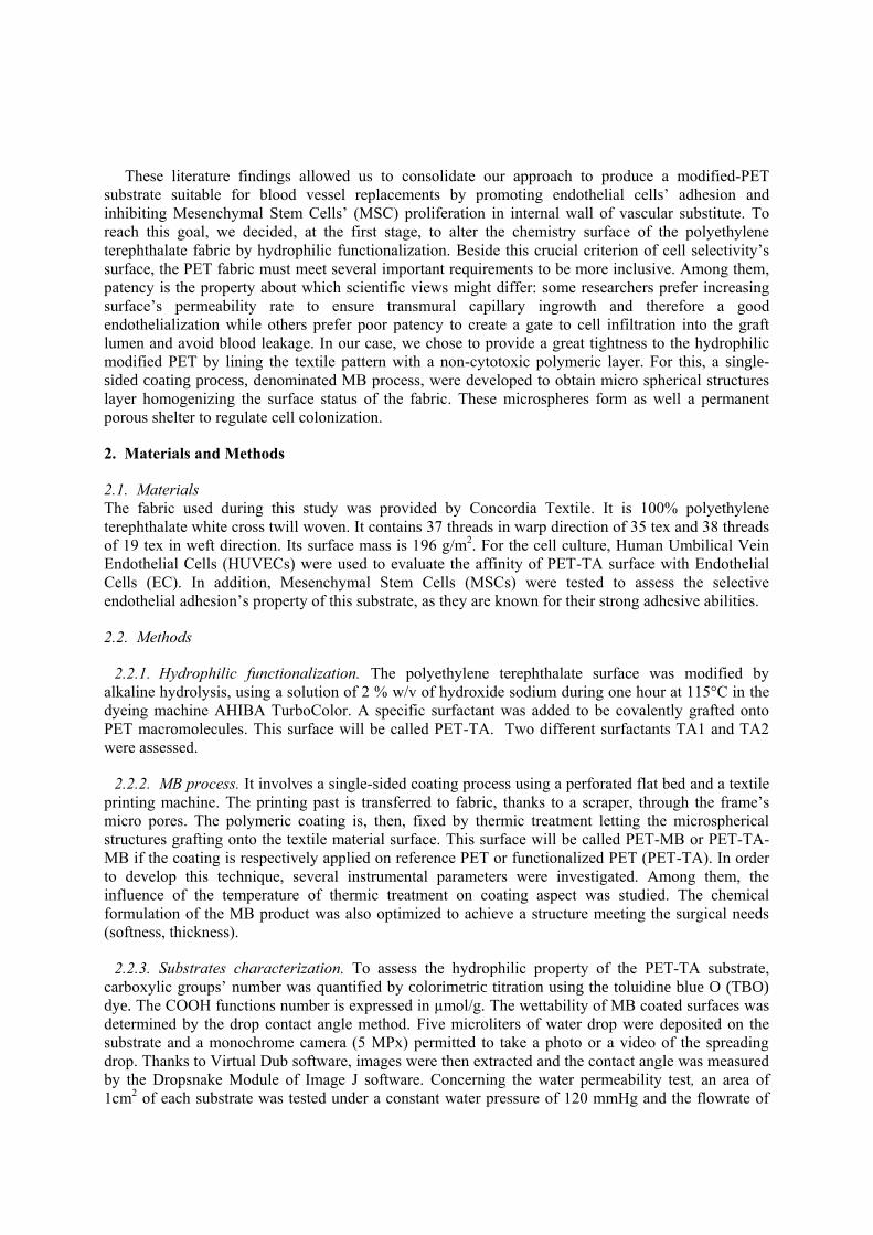
temperature (Tg) of the copolymer MB from 0.13°C to -3.67°C. In fact, as observed in the SEM image
(figure 2(d)), the microspheres are more dispersed in monolayer reducing thus the MB treatment’s
thickness.
(a) Non-treated PET (b) MB -90°C (c) MB-110°C (d) MB+ PEG + CLAR
Figure 2. SEM Observations (x40): (a) Non-treated PET, (b) and (c) the influence of the temperature
on the coating aspect, (d) microspheres distribution after adding plasticizer (PEG) and binding agent
(CLAR) at 110°C.
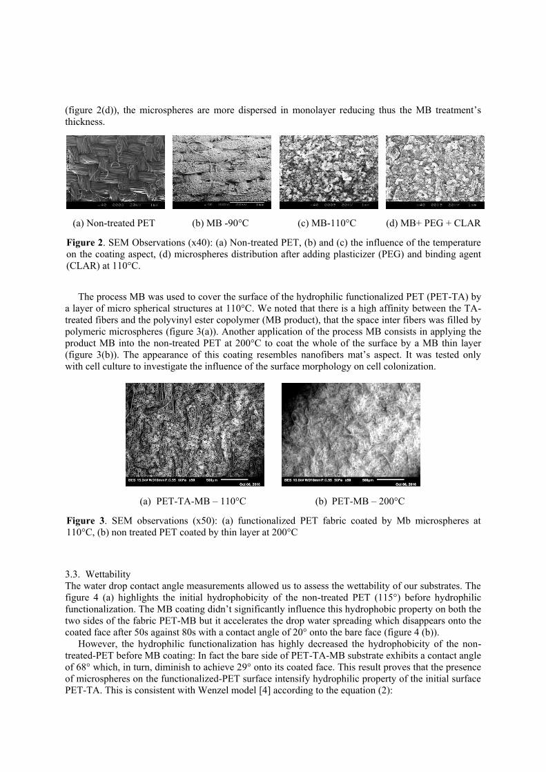
The process MB was used to cover the surface of the hydrophilic functionalized PET (PET-TA) by
a layer of micro spherical structures at 110°C. We noted that there is a high affinity between the TA-
treated fibers and the polyvinyl ester copolymer (MB product), that the space inter fibers was filled by
polymeric microspheres (figure 3(a)). Another application of the process MB consists in applying the
product MB into the non-treated PET at 200°C to coat the whole of the surface by a MB thin layer
(figure 3(b)). The appearance of this coating resembles nanofibers mat’s aspect. It was tested only
with cell culture to investigate the influence of the surface morphology on cell colonization.
(a) PET-TA-MB – 110°C (b) PET-MB – 200°C
Figure 3. SEM observations (x50): (a) functionalized PET fabric coated by Mb microspheres at
110°C, (b) non treated PET coated by thin layer at 200°C
3.3. Wettability
The water drop contact angle measurements allowed us to assess the wettability of our substrates. The
figure 4 (a) highlights the initial hydrophobicity of the non-treated PET (115°) before hydrophilic
functionalization. The MB coating didn’t significantly influence this hydrophobic property on both the
two sides of the fabric PET-MB but it accelerates the drop water spreading which disappears onto the
coated face after 50s against 80s with a contact angle of 20° onto the bare face (figure 4 (b)).
However, the hydrophilic functionalization has highly decreased the hydrophobicity of the non-
treated-PET before MB coating: In fact the bare side of PET-TA-MB substrate exhibits a contact angle
of 68° which, in turn, diminish to achieve 29° onto its coated face. This result proves that the presence
of microspheres on the functionalized-PET surface intensify hydrophilic property of the initial surface
PET-TA. This is consistent with Wenzel model [4] according to the equation (2):

cosθw = r. cosθ (2)
Where θ represents contact angle onto a flat surface, θW is the contact angle onto rough surface of the
same material and r is the roughness.
(a) (b)
Figure 4. Wettability Test: (a) Contact angle measurements, (b) Water drop spreading
3.4. Water permeability
The test of water permeability (figure 5) demonstrates that the MB coated fabrics became extremely
impermeable to the water for both PET-MB and PET-MB-TA. The water permeability decreases from
900 to 4 ml/min.cm2. This impermeability property is necessary to avoid bleeding through the
prosthesis wall.
Figure 5. Water Permeability Test
3.5. Cell culture
The cell culture graphs (figure 6 (a) and (b)) display the number of seeded Mesenchymal Stem Cells
(MSC) onto non-treated PET, hydrophilic functionalized PET (PET-TA), PET-MB and fabric lined by
thin MB layer at 200°C (PET-MB-200) during 2 and 3 days.
A decrease of 50% and 28% of adhered MSC onto PET-TA comparing to non-treated PET was
noted after respectively 2 and 3 days of culture. Concerning the MB coating, the thin MB layer
covering the PET surface (PET-MB-200), which resembles to a polymeric nanofibers mat, promoted
the same MSC proliferation than the reference PET surface: no significant difference has been
observed after 3 days of cell seeding. However, the micro spherical structures’ coating of PET-MB
reduced the MSC adhesion by 37 % and their proliferation after 3 days by almost 50% comparing to

the flat PET. Regarding to the HUVEC (figure 6 (c)), the PET-TA substrate enhanced their
proliferation by 47% after 3 days of culture. These results allowed us to infer the influence of
hydrophilic property to enable a fast and selective endothelialization and the importance of rough
surface to foster controlled MSC proliferation.
(a) Influence of hydrophilic
functionalization on MSC
attachment
(b) Influence of MB coating on
MSC attachment
(c) Influence of hydrophilic
functionalization on HUVEC
attachment
Figure 6. Cell culture on non-treated PET, PET-TA, PET-MB and PET-MB-200. The control is the
well without any fabric
4. Conclusion
Hydrophilic functionalization of the polyethylene terephthalate was carried out by alkaline hydrolysis
in the presence of an electrolyte and 0.5% w/v of specific surfactant TA1 at 110°C. This treatment
brought to the PET surface an important carboxylic functions’ amount of 11µmol/g that made it
hydrophilic. It was shown that this chemical surface alteration improved the endothelial cells’
proliferation by 47%.
The MB process was optimized to cover the PET surface with micro spherical structures’
polymeric layer. This MB coating provided to the PET substrate high water impermeability to ensure a
great tightness of the textile material. The roughness created by the microspheres onto the PET-TA
surface enhanced its hydrophilic property. This curvilinear topography reduced the MSC adhesion and
regulated their proliferation. Therefore, we obtained a hydrophilic impermeable-modified
polyethylene terephthalate (PET-TA-MB) able to promote endothelialization and inhibit unwanted
cells recruitment. In pursuing our work, micro spherical structures will be exploited to incorporate
peptides inhibiting platelet aggregation. Such a coating could be interestingly applied in the field of
the functionalization of internal walls of vascular substitutes.
References
[1] Shi L, Aid R, Le Visage C and al. 2012 Biomimicking Polysaccharide Nanofibers Promote
Vascular Phenotypes: A Potential Application for Vascular Tissue Engineering
Macromolecular Bioscience 12 pp. 395-401
[2] Sabatier G Conception et élaboration d’échafaudages de nanofibres à dégradation contrôlée
pour des applications en médecine régénratrice vasculaire, Phd thesis, Université Laval
Quebec, Canada and Université de Haute Alsace Mulhouse, France p 283
[3] ISO. Cardiovascular implants – Tubular vascular protheses. ISO/FDIS 7189, 1998, p 47
[4] Wenzel N 1979 Surface Roughness and contact angle Journal of Physical Chemistry 53 pp.
1466-67

Electrospun polymeric dressings functionalized with
antimicrobial peptides and collagen type I for enhanced
wound healing
H P Felgueiras1 and M T P Amorim
Centre for Textile Science and Technology, Department of Textile Engineering, University of
Minho, Campus de Azurém, 4800-058 Guimarães, Portugal
Email: [email protected]
Abstract. Modern wound dressings combine medical textiles with active compounds that
stimulate wound healing while protecting against infection. Electrospun wound dressings have
been extensively studied and the electrospinning technique recognized as an efficient approach
for the production of nanoscale fibrous mats. The unique diverse function and architecture of
antimicrobial peptides (AMPs) has attracted considerable attention as a tool for the design of
new anti-infective drugs. Functionalizing electrospun wound dressings with these AMPs is
nowadays being researched. In the present work, we explore these new systems by highlighting
the most important characteristics of electropsun wound dressings, revealing the importance of
AMPs to wound healing, and the methods available to functionalize the electrospun mats with
these molecules. The combined therapeutic potential of collagen type I and these AMP
functionalized dressings will be highlighted as well; the significance of these new strategies for
the future of wound healing will be clarified.
1. Introduction
Wound dressing design and fabrication are important segments of the textile medical and
pharmaceutical wound care market worldwide. In the past, traditional dressings were used to simply
manage the wound, to keep it dry and prevent bacterial entrance. Nowadays, the fabrication of wound
dressings aims to create an optimal environment that accelerates wound healing, while promoting
oxygen exchange and intensively preventing microbial colonization [1].
Electrospinning has become one of the most popular processes to produce medical textiles in the
form of wound dressings. This is a simple and effective method to produce nanoscale fibrous mats
with controlled pore size and structure, from both natural and synthetic origin polymers. This
technique has gain much attention because of its versatility, reproducibility, volume-to-surface ratio
and submicron range [2-4]. Recently, functionalizing these electrospun wound dressings with active
compounds that accelerate wound healing and tissue regeneration has become the major goal [5]. The
rising of antibiotic-resistant infection agents has increased the need for such therapies. While
antibiotics act selectively against bacteria, dressings functionalized with antimicrobial peptides
(AMPs) act at multiple sites within microbial cells, reducing the likelihood of bacteria to develop
resistance [6]. The combination of collagen type I (Col I), one of the most important extracellular

matrix (ECM) proteins to wound healing, with these AMP-polymer mat systems has yet to be
investigated. Col I has been highlighted as uniquely suited for wound dressing therapies because of its
involvement in all phases of wound-healing [7]. Thus the combination of Col I with the AMPs would
represent a new step further in the optimization/development of new generation wound dressings.
In the present paper, we reviewed the basic concepts associated with electrospinning technique and
explored the use of AMPs in wound healing. Further, we established AMPs functionalization methods
and highlighted the importance of Col I to tissue regeneration.
2. Electrospun Wound Dressings
Electrospinning is a cost-effective, simple and straightforward technique, that allows the production of
continuous nanofibers with specific properties. Modern dressings are design to facilitate wound
healing, protect the wounded site from repeated trauma and prevent infection. It has been established
that the ideal dressing should be haemostatic, absorb exudates, maintain moisture balance, protect
against pathogens, adapt to the wounded site, cause no pain and be low cost [2-4]. Nanofibrous mats
produced by eletrospinning may accommodate all these demands.
2.1. Technique: Principles
Electrospinning is based on the principle that strong mutual electrical repulsive forces overcome
weaker forces of surface tension in the charged polymer liquid. It is capable of consistently produce
fibers in the submicron range, from 2 nm to several micrometers, with extremely high surface-to-
volume ratio, tunable porosity and malleability. The equipment consists of a syringe needle connected
to a high DC voltage source of tens of kVs that generates an electrical field with the collecting plate
and impels the polymer solution to extrude. As it is released, the polymer solution jet becomes
unstable and elongates, subdividing geometrically into nanofiber jets that are collected at an optimal
distance. At the same time, the volatile organic solvent used to prepare the polymer solution
evaporates. In the end, a mat composed of individual continuous nanofibers is obtained [2-4].
The mat's topography, morphology and fiber orientation are defined by the operating conditions
(applied voltage, flow rate, distance to collector), solution properties (polymer concentration,
viscosity, solvent volatility, surface tension, conductivity) and environment conditions (temperature,
humidity) [8]. By modifying and adapting these parameters to fit our wounds demands, multiple
distinct nanofibrous medical textiles can be produced.
2.2. Natural and Synthetic Polymers for Wound Dressings
Natural polymers, which derive from renewable sources, are widely used in medicine regenerative
because of their intrinsically bioactive and biodegradable properties and similarity to the ECM.
Between the many, polysaccharides, including cellulose, hyaluronic acid, chitin, chitosan, alginates,
etc., are the most extensively used to manage and treat wounds. Cellulose is perhaps the most used as
it is an abundant polysaccharide based on glucose of particular interest to wound healing due to its
flexibility, unique nanostructure and remarkable physical-chemical properties, biocompatibility,
biodegradability, hydration capacity and antimicrobial features [9].
Many formulations of individual or blends of synthetic polymers have been investigated for the
production of dressings with successful results, including poly(ɛ-caprolactone) (PCL), polyurethane
(PU) and poly(vinyl alcohol) (PVA). PCL is bioresorbable and biocompatible and has been applied for
the production of wound dressing since the 1970s [10]. PU is a biodegradable hydrophobic polymer
with excellent mechanical properties, high elongation capacity, good abrasion resistance, high
flexibility and hardness, and blood compatibility [11]. As a biodegradable, non-toxic or carcinogenic,
biocompatible polymer with good mechanical properties, PVA is desirable for wound healing due to
its flexibility and swelling capacity in aqueous environments [12].

3. Antimicrobial Peptides
From a microbiological point of view, the primary function of intact skin is to prevent invasion and
colonization of potential pathogens. Exposure of subcutaneous tissue, following loss of skin integrity,
provides a moist, warm, and nutritious environment for microorganisms to colonize and proliferate. To
fight these infections, multicellular organisms have evolved and develop an arsenal of host-defense
molecules, the AMPs. These natural and synthetic peptides provide a non-specific defense against a
broad spectrum of invaders, such as bacteria, fungi, and certain viruses, acting like a component of
innate immunity [5].
AMPs are low molecular weight molecules composed of 5 to 100 amino acid residues. AMPs are
often cationic due to the excess of lysine, arginine and histidine amino acids, and most AMPs are
amphipatic, containing both hydrophilic and hydrophobic amino acid residues organized in a helical
molecule. The amphipatic helical structure is most effective interacting with biomembranes, since it
endows the AMPs with the capacity to bind to lipid components (hydrophobic regions) and
phospholipid groups (hydrophilic regions) [13]. AMPs can be subdivided in four main classes,
according to its structural diversity: α-helix, β-sheet, extended and loop. The α-helix and β-sheet
configurations are the most common; the first is formed only when the peptide contacts with a
membrane, and the second is stabilized by 2 to 4 disulfide bonds. The less common, extended and
loop, display a curved form in response to a simple disulfide bond or the presence of proline residues
in its structure. AMPs can also be classified based on their target microorganism: antibacterial
peptides (most common), which target the cell membranes disintegrating the lipid bilayer structure;
antiviral peptides, which neutralize the viruses by integrating in either the viral envelope or the host
cell membrane; antifungal peptides, which kill by targeting either the cell wall or the intracellular
components; and antiparasitic peptides, which kill by direct interaction with the cell membrane [6].
3.1. AMPs in Wound Healing
AMPs are found in a variety of tissues. They were first observed in mammalian skin in the form of
cathelicidin PR-39 [14]. Later, human cathelicidin hCAP-18 was detected in epidermal keratinocytes.
Since then, many others, like the human defensin hBD-3, were studied and cloned for wound healing
purposes [15].
The hCAP-18 is the only human cathelicidin. It is found in specific granules of neutrophils, in
keratinocytes during skin inflammation or even in the lungs. Plasma contains, as well, a high
concentration of hCAP-18 bound to lipoproteins. The LL-37, which is the antibacterial C-terminus of
hCAP-18, displays broad antimicrobial activity against both Gram-positive and Gram-negative
bacteria, has synergistic antibacterial effects with defensins, and is a potent chemoattractant agent for
neuthophils, monocytes and T cells. LL-37 has been shown to be up-regulated in the skin following
injury and, thus, to increase its sensibility towards infection [16,17]. The human β-defensin-3 or hBD-
3 possesses a broad bactericidal activity against both Gram-positive and Gram-negative bacteria, and
has also been associated with increased cytokine secretion and keratinocytes expression, cell migration
and proliferation, enhanced anti-inflammatory activity, and accelerated wound closure [18].
Aside from human-derived AMPs, there are others from amphibian, vertebrate, insect or pathogen
origins that have revealed great results as wound healing promoters. The isolation of magainins from
Xenopus laevis species led to the discovery of a wide range of amphibian peptides of great potential.
Pexiganan, for instance, was one of the first AMPs to be synthesized from mangainin. It is mainly
applied in the treatment of infected wounds, including diabetic ulcers, and has been shown to reduce
microbial burden. Pexiganan is also known to stimulate migration of cells involved in tissue
reconstruction [19].
3.2. AMPs Functionalization
Following concerns over the development and spread of antibiotic-resistant strains of bacteria, the use
of dressings that combine AMPs with well-established biomedical polymers has increased.
Functionalizing AMPs onto electrospun dressings has become a most important process [20].
There are many strategies used to immobilize AMPs onto electrospun dressings. The most common
and simplest is the co-spinning method. Here, AMPs are immobilized as the polymeric nanofibers are
produced. Multifunctional bioactive nanofibrous dressings, with an all-in-one approach, are therefore
the result of co-spinning [21]. Physical adsorption methods, which include adsorption and layer-by-
layer assembly, involve physisorption of AMPs through non-covalent or multidentate interactions at
the electrospun surface. Adsorption is the most straightforward approach. It requires only the
immersion of the electrospun mats in a solution containing the selected AMPs, for the time required to
reach saturation. This method, however simple, is most challenging without using binding agents, as
quick desorption of the AMPs in response to mechanical forces remains a complication. In the layer-
by-layer approach, AMPs are sandwiched between two polyionic polymers. Using this method a
flexible number of layers with controlled AMP loading can be prepared by exchanging electrospun
solutions at the appropriate time. As a downside, the AMPs immobilized in between layers may have
more difficulties to diffuse towards the wounded site [22].
Compared to physical immobilization, covalent binding offers many more advantages, including
minimizing AMPs leaching, providing long-term stability and lowering toxicity. It can be
accomplished by two ways: "graft to" approach, which involves the covalent coupling of the intact
AMPs to the electrospun surface; or "surface initiated" strategy, which requires the synthesis of the
AMPs from initiators or spacers bearing reactive groups covalently immobilized onto the mat's
surface. "Graft to" strategies entail the activation of the electrospun surfaces to generate free binding
groups like amines, carboxylic acids, aldehydes or thiols. More often than expected, the linkage
between these free functional groups and the AMPs may be hydrolyzed or broken by mechanical
forces, even though the covalent bonds created are strong and irreversible [20]. Polymer resins like
polyethylene glycol (PEG) are frequently functionalized onto electrospun dressings to induce "surface
initiated" immobilization. As a linker, PEG aside from reducing bacteria interactions also allows rapid
and free orientation of the bound AMPs at the interface, thus enhancing the protective performance of
the bound AMPs and its action mode [23].
4. Collagen Type I in Wound Healing
Collagen is an extremely important ECM protein, majorly present in the connective tissues (i.e.
tendons, bone, skin, etc.). 25-35% of the total amount of proteins in the human body are collagen and,
from the 16 existing types, Col I is the most common, representing near 90% of the organic mass of
bone [24]. Col I has an excellent biocompatibility, which makes it popular in artificial tissue and
wound dressings manufacture. The native fibrillar collagen is the most important polymorphic form of
collagen, which makes manufacture of fibrous dressing products possible [25]. In the form of wound
dressings, Col stimulates the wound healing cellular and molecular cascades, development of new
tissues and wound debridement [26]. In fact, Col I has been highlighted as uniquely suited for wound
dressing therapies because of its involvement in all phases of wound-healing. Platelets aggregate
around exposed collagen and secrete factors that stimulate the intrinsic clotting cascade responsible for
a stable hemostatic "plug". Further, collagen-based wound dressings have been shown to address the
issue of elevated levels of matrix metalloproteinases, a key component of chronic wounds known to
degrade non-viable and viable collagen, by acting as "sacrificial substrates" in the wound [7]. Collagen
fibrils have been combined with other polymeric matrixes to produce dressings with the ability to
absorb wound exudates to maintain a moist environment and, thus, stimulate wound healing [27,28].
5. Conclusions and Future Perspectives
Due to the continue rising of antimicrobial resistant pathogens, the need for engineered alternated
treatments for acute to chronic wound care has increased. As a first strategy to overcome this issue,
AMPs have been loaded onto existing textile medical dressings to improve their healing and
antimicrobial capacities. We highlighted the most well known AMPs and the most appropriate
methods to functionalize the surface of electrospun mats with such molecules. This is still a very new
formulation and further research should be conducted. Indeed, long-term therapeutics using AMPs

functionalized dressings should be carefully evaluated to prevent the risk of compromising our innate
immune defense and, therefore, the ability to control commensal microbiome and microbial infections.
Functionalizing surfaces with AMPs should be managed by standardized tests that not only evaluate
the action of the AMPs but as well its stability, releasing abilities and tunable performance. The level
of control in peptide loading and release timescales that are required in applications that could benefit
from such antimicrobial profile has thus far not been demonstrated. Because they are still being
developed and tested, these systems, AMPs-polymeric mat, should be cautiously defined so that the
best combination between selected polymer, mechanism of action, AMPs and immobilization process
is achieved. Although Col I has been extensively used in wound healing and its potential already
demonstrated, the combination with AMPs-polymeric mats systems has yet to be explored. In a near
future, we intend to examine the synergistic performance of these molecules in the treatment of
chronic wounds, namely diabetic ulcers. We are confident these new systems aside from acting against
the pathogens will also accelerate the wound healing process by establishing a symbiotic action.
Acknowledgments
This work is financed by FEDER funds through the Competitivity Factors Operational Programme -
COMPETE and by national funds through FCT – Foundation for Science and Technology within the
scope of the project POCI-01-0145-FEDER-007136
References
[1] Vowden K and Vowden P 2014 Surgery 32 462-67.
[2] Liang D, Hsiao BS and Chu B 2007 Adv. Drug Deliv. Rev. 59 1392-1412.
[3] Hunley MT and Long TE 2008 Polym. Int. 57 385-9.
[4] Lannutti J, Reneker D, Ma T, Tomasko D and Farson D 2007 Mater. Sci. Eng. C 27 504-9.
[5] Reddy K, Yedery R and Aranha C 2004 Int. J. Antimicrob. Agents 24 536-47.
[6] Bahar AA and Ren D 2013 Pharm. 6 1543-75.
[7] Brett D 2008 Wounds 20 347-56.
[8] Bhardwaj N and Kundu SC 2010 Biotechnol. Adv. 28 325-47.
[9] Czaja W, Krystynowicz A, Bielecki S and Brown RM 2006 Biomaterials 27 145-51.
[10] Yoshimoto H, Shin Y, Terai H and Vacanti J 2003 Biomaterials 24 2077-82.
[11] Francois P, Vaudaux P, Nurdin N, Mathieu H, Descouts P and Lew DP 1996 Biomaterials 17
667-78.
[12] Tarun K and Gobi N 2012 IJFTR 37 127-32.
[13] Brogden KA 2005 Nature Rev. Microbiol. 3 238-50.
[14] Gallo RL, Ono M, Povsic T, Page C, Eriksson E, Klagsbrun M and Bernfield M 1994 Proc.
Natl. Acad. Sci. 91 11035-39.
[15] Frohm M, Agerberth B, Ahangari G, Ståhle-Bäckdahl M, Lidén S, Wigzell H and
Gudmundsson GH 1997 J. Biol. Chem. 272 15258-63.
[16] Ramos R, Silva JP, Rodrigues AC, Costa R, Guardão L, Schmitt F, Soares R, Vilanova M,
Domingues L and Gama M 2011 Peptides 32 1469-76.
[17] Scott MG, Davidson DJ, Gold MR, Bowdish D and Hancock RE 2002 J. Immunol. 169 3883-
91.
[18] Hirsch T, Spielmann M, Zuhaili B, Fossum M, Metzig M, Koehler T, Steinau HU, Yao F,
Onderdonk AB and Steinstraesser L 2009 J. Gene Med. 11 220-28.
[19] Gopinath D, Kumar MS, Selvaraj D and Jayakumar R 2005 J. Biomed. Mater. Res. A 73 320-
31.
[20] Green J-BD, Fulghum T and Nordhaus MA 2009 Chem. Rev. 109 5437-5527.
[21] Zhang Y, Lim CT, Ramakrishna S and Huang Z-M 2005 J. Mater. Sci. 16 933-46.
[22] Shukla A, Fleming KE, Chuang HF, Chau TM, Loose CR, Stephanopoulos GN and Hammond
PT 2010 Biomaterials 31 2348-57.
[23] Cho W-M, Joshi BP, Cho H and Lee K-H 2007 Bioorg. Med. Chem. Lett. 17 5772-6.

[24] Pareti FI, Fujimura Y, Dent JA, Holland LZ, Zimmerman TS and Ruggeri Z 1986 J. Biol.
Chem. 261 15310-5.
[25] Rajendran S and Anand S 2002 Text. Prog. 32 1-42.
[26] Albu M, Ferdes M, Kaya D, Ghica M, Titorencu I, Popa L and Albu L 2012 Mol. Cryst. Liq.
Cryst. 555 271-9.
[27] Wen X, Zheng Y, Wu J, Wang L-N, Yuan Z, Peng J and Meng H 2015 Int. J. Nanomedicine 10
4623.
[28] Helary C, Abed A, Mosser G, Louedec L, Letourneur D, Coradin T, Giraud-Guille MM and
Meddahi-Pellé A 2015 Biomaterials Sci. 3 373-82.
Stress adapted embroidered meshes with a graded pattern
design for abdominal wall hernia repair
J Hahn, L Bittrich, A Breier, and A Spickenheuer
Leibniz-Institut für Polymerforschung Dresden e. V., Institute of Polymer Materials,
Department of Composite Materials, Hohe Str. 6, 01069 Dresden, Germany
Email: [email protected]
Abstract. Abdominal wall hernias are one of the most relevant injuries of the digestive system
with 25 million patients in 2013. Surgery is recommended primarily using allogenic non-
absorbable wrap-knitted meshes. These meshes have in common that their stress-strain
behaviour is not adapted to the anisotropic behaviour of native abdominal wall tissue. The ideal
mesh should possess an adequate mechanical behaviour and a suitable porosity at the same
time. An alternative fabrication method to wrap-knitting is the embroidery technology with a
high flexibility in pattern design and adaption of mechanical properties. In this study, a pattern
generator was created for pattern designs consisting of a base and a reinforcement pattern. The
embroidered mesh structures demonstrated different structural and mechanical characteristics.
Additionally, the investigation of the mechanical properties exhibited an anisotropic
mechanical behaviour for the embroidered meshes. As a result, the investigated pattern
generator and the embroidery technology allow the production of stress adapted mesh
structures that are a promising approach for hernia reconstruction.
1. Introduction
A hernia of the abdominal wall is a protrusion of the intestine through a defect or an area of weakness
of the wall. The reason for hernia appearance mainly is due to a connective tissue weakness. Because
of acute complications like bowel obstructions, an immediate surgery is required. The worldwide
incidence of abdominal hernias is estimated to about 25 million per year. A common method for
hernia repair is the implantation of synthetic non-absorbable meshes to support the natural tissue.
About one million meshes are implanted every year worldwide [1]. An ideal mesh should provide an
adequate porosity for tissue integration, a mechanical behaviour comparable to that of the healthy
abdominal wall, and the ability to absorb physiological loads [2-4].
The majority of the used meshes are fabricated by wrap-knitting and exhibit significant higher
ultimate load values and no adaption to the anisotropic mechanical behaviour of native healthy
abdominal wall tissue [5, 6]. Pott et al. (2012) investigated the mechanical properties of six different
knitted hernia meshes in longitudinal and transversal direction. They measured significant differences
for ultimate tensile load ((11.1 ± 6.4 to 100.9 ± 9.4) N/cm), stiffness ((0.3 ± 0.1 to 4.6 ± 0.5) N/mm)
and break elongation ((150 ± 6 to 340 ± 20) %) values considering the loading direction [7]. The force
values for all tested meshes were significantly different in longitudinal and transversal direction,
respectively. Furthermore, this anisotropic mechanical behaviour is not visible on most of the hernia
meshes resulting in a wrong positioning during surgery and an increasing recurrence rate for the
patients [8, 9]. Therefore, the anisotropic mechanical behaviour of warp-knitted meshes is

demonstrated by these results confirming the paramountcy of the orientation as well as the necessity to
transfer this information from the manufacturers to the surgeons.
An alternative fabrication method could be the embroidery technology. This technology allows the
production of structures in nearly all dimensions with high design variability associated with minor
effort in pattern creation and machine adjustments compared to warp-knitted fabrics. Embroidered
structures are already used for tissue engineering approaches like bone scaffolds [10-12] or for the
reconstruction of the anterior cruciate ligament [13, 14].
2. Materials and methods
2.1. Pattern design
Stitch patterns are generated by scripted algorithms based on input design parameters. Stitch positions
and the stitch thread path strongly influence the elastic properties of the final structure. The successive
stitch position data then is transformed by CAM-software like EDOpath to a machine readable CNC
data format. Composition and design parameters of a pattern are presented in Figure 1.
Figure 1. Pattern
design for mesh
structures composed
of base (green) and
reinforcement (red
with blue dots)
pattern
The objective of this pattern design is a tailored stress-strain behaviour showing a high strength at
the location of damaged abdominal wall tissue and a soft transition region to healthy tissue to avoid
recrudescence due to stress peaks at the mesh boundary. The base pattern (Fig. 1 green) serves as
ground fabric for the reinforcement pattern and should ensure appropriate porosity and elasticity. It
enables the variation of four parameters, stitch length (distance between two green dots), stitching shift
(distance between two green lines (Fig. 1a)) as well as length (Fig. 1b) and width (Fig. 1c) of the
complete base pattern. In contrast, the reinforcement pattern (Fig. 1 red with blue dots) allows the
precise adaption of the mechanical behaviour for the whole mesh structure due to eight different
design parameters. Four parameters are analogous to those of the base pattern, stitch length (distance
between two blue dots), stitching shift (distance between two red lines (Fig. 1d)) as well as length
(Fig. 1e) and width (Fig. 1f) of the reinforcement pattern. The stretched thread length (Fig. 1g) in the
middle of the pattern, the wavelength (Fig. 1h) and the minor/major amplitude (Fig. 1i/j) can be varied
to design a graded transition with regions of high stiffness and strength in the range of the hernia
opening and regions of high elasticity for the transition to the base pattern.
2.2. Embroidery technology
The meshes were fabricated using an embroidery machine (ZSK JCZ 0209-550, ZSK
Stickmaschinen GmbH, Krefeld / Germany) with a multi-needle header on a water soluble

polyvinylalcohol (PVA, Freudenberg, Weinheim/Germany) nonwoven. This base material was washed
out after the embroidery process in warm water for 90 minutes remaining a porous mesh structure [16,
19].
Figure 2. Specimen 1
for tensile testing
(testing area red
framed) with a mesh
structure consisting
of a base (green) and
a reinforcement
(blue) pattern design
arranged in
longitudinal or
transversal direction
A commercial monofilament based on polypropylene (PP, Dr. Karl Wetekam & Co. KG,
Melsungen / Germany) with a yarn count of Tt = 6.4 tex was used as thread material. The embroidered
meshes were composed of the base pattern (Fig. 2 green) and the reinforcement pattern (Fig. 2, blue).
The base pattern (specimen 1: 2.0 mm stitch length, 1.5 mm stitching shift) was embroidered on the
PVA in the first fabrication process. After that, the reinforcement pattern (specimen 1: 2.0 mm stitch
length, 1.5 mm stitching shift, 20 mm length of stretched thread, 2.0 mm wavelength,
0.5 mm / 5.0 mm minor / major amplitudes) was positioned directly over the base pattern in
longitudinal (Long) or transversal (Trans) orientation. The orientation of the graded reinforcement
pattern was investigated for specimen 1 in respect to its influence on the load-elongation behaviour
and mechanical properties.
2.3. Mechanical testing
The mechanical properties were investigated using a uniaxial tensile testing machine (Zwick / Roell
Z2.5, Ulm / Germany) controlled with TestXpert software. A 1000 N load sensor and pneumatic metal
clamps were used. The specimens were prepared with a length of 100 mm and a width of 40 mm. The
gauge length was set at 50 mm (Fig. 2, red frame). The test speed was 100 mm/min. Ten specimens
for each reinforcement pattern orientation were tested. Three mechanical values were determined from
the load-displacement curves as described before [13]. The maximum load value defines the ultimate
tensile load Fmax (in N). The associated displacement lmax at Fmax specifies the ultimate tensile
elongation εmax (in %) with 𝜀𝑚𝑎𝑥 = (𝑙𝑚𝑎𝑥 𝑙𝑔𝑎𝑢𝑔𝑒⁄ ) ∙ 100. The stiffness S (in N/mm) is defined as ratio
of the applied load ΔF to displacement Δl in the linear slope of the load-displacement curve. In
addition, the elongation εF=5N (in %) at a load of 5 N was evaluated to define and compare the
structural deformation of the embroidered specimen. Results for mechanical properties were
represented as boxplot with the first (bottom band) and third (top band) quartiles as well as the median
(inside band). Mean values (dots) and standard deviations (positive and negative whiskers) were
additionally specified. The significance level was set at 5 % (p < 0.05).
3. Results
Diverse patterns for embroidered mesh structures with high design variability were realized in this
study. Different textile parameters were varied and resulted in mesh structures with adjustable
structural characteristics (Fig. 3). For example, porosity and pore sizes could be influenced by varying

stitch length and density of the base pattern (Fig. 3 A, B) or minor and major amplitude of the
reinforcement pattern (Fig. 3 C, D).
Figure 3. Examples for different pattern designs for embroidered mesh structures (base pattern: length
150 mm, width 100 mm; reinforcement pattern: length 130 mm, width 80 mm)
Figure 4. Exemplary
load-elongation
curves of
embroidered mesh
structures for
specimen 1 with the
reinforcement pattern
oriented longitudinal
(Long) and
transversal (Trans) to
the tension direction
Anisotropic material properties were demonstrated by orienting the reinforcement pattern
longitudinally and transversally to the direction of tension for mechanical testing (Fig. 4). The pattern
oriented in longitudinal direction exhibited a significantly higher ultimate tensile load (34 N ± 3 N vs.
31 N ± 3 N) compared to the transversally arranged pattern (Fig. 5 A). In contrast, the ultimate tensile

elongation (55 % ± 5 % vs. 71 % ± 6 %) and the elongation at 5 N (19 % ± 2.5 % vs. 33 % ± 3.2 %)
values were significantly lower in the longitudinal compared to the transversal direction (Fig. 5 B, C).
Only the stiffness values for both mesh types were in the same range and showed high mean variations
(2.2 N/mm ± 0.5 N/mm vs. 2.4 N/mm ± 0.7 N/mm) (Fig. 5 D).
Figure 5. Mechanical properties of the embroidered mesh structures for specimen 1 tested in
longitudinal (Long) and transversal (Trans) direction, A – ultimate tensile load (Fmax in N), B –
ultimate tensile elongation (εmax in %), C – elongation at load F = 5 N (εF=5N in %) and D – stiffness (S
in N/mm)
4. Discussion
For an optimal reconstruction of abdominal wall hernias, it is essential to use a mesh with adapted
stress-strain behaviour and adequate mechanical properties comparable to those of healthy tissue [1].
Challenging in this field is the insufficient data situation regarding in vivo information about the
mechanical properties of abdominal wall tissue. Therefore, a fabrication method for hernia meshes has
to be chosen that offers the possibility to adapt the mechanical and structural properties individually.
This work presents the first demonstration of the feasibility of embroidery technology for
producing hernia mesh structures with a specific adaption of the pattern design (Fig. 3) and thus of
mechanically adapted structures (Fig. 4). This adaptability was also demonstrated in studies regarding
a mechanically adjusted scaffold design for the reconstruction of the anterior cruciate ligament [13].
Stress-strain behaviour and mechanical properties were affected by different pattern design parameters
or material selection. The pattern design influences the stress-strain behaviour of the structural
deformation of the textile mesh while the material deformation is diversified by the selected thread
material. Force values for the embroidered meshes were lower compared to commercial hernia meshes
but by varying thread material or size the mechanical properties could be improved. The used thread

material (polypropylene (PP)) has an ultimate load Fmax of 2.8 N. Established thread materials for
hernia meshes like medical grade PP or polyvinylidene difluoride (PVDF) were investigated and
exhibited Fmax between 2.3 N – 8.3 N and 3.4 N – 10.8 N depending on their yarn count. This wide
range in the thread material characteristics is useful to adjust the ultimate tensile properties of the
embroidered meshes. Nevertheless, the vital non-linear behaviour in the elasticity could be
demonstrated.
The embroidered meshes were composed of two different design structures, an almost isotropic
support structure and a directional reinforcement structure. This twofold design enabled clearly
different elastic properties for transversal and longitudinal loads applicable for mimicking the
behaviour of natural tissue. Especially the strain behaviour showed the strongest directional
dependence. The maximum load also exhibited a directional effect. However, clamping of the
specimens was not applied at the reinforcement structure but extended to the environing transition
patterns modifying the effect to lower values. Future works will focus on the targeted tailoring of this
anisotropic behaviour to the behaviour of human tissue and thus improve medical applicability.
5. Conclusion
In this study different pattern designs were created by various parameters composing a mesh structure
with a base and a reinforcement pattern. Based on these designs, mesh structures were fabricated using
embroidery technology. An adjustable anisotropic mechanical behaviour was presented for these
embroidered meshes. Ongoing experiments consider the adjustments of the ultimate tensile properties,
the determination and their influence on the mechanical behaviour of various numbers of design
parameters, especially for the reinforcement pattern, as well as the use of these data for numerical
simulation of the stress-strain behaviour.
6. References
[1] Schumpelick V 2001 Hernia 5 5-8
[2] Brown CN and Finch JG 2010 Ann R Coll Surg Engl 92 272-8
[3] Klinge U and Weyhe D 2014 Chirurg 85 105-11
[4] Zhu L-M, Schuster P and Klinge U 2015 World J Gastrointest Surg 7 226-36
[5] Kalaba S, Gerhard E, Winder J S, Pauli E M, Haluck R S and Yang J 2016 Bioact. Mat. 1 2-17
[6] Sanbhal N, Miao L, Xu R, Khatri A and Wang L 2017 J. Ind. Text. 1-28
[7] Pott PP, Schwarz MLR, Gundling R, Nowak K, Hohenberger P and Roessner ED 2012 PLOS
ONE 7 1-10
[8] Saberski ER, Orenstein SB, Novitsky YW 2011 Hernia 15 47-52
[9] Binnebösel M, Rosch R, Junge K, Flanagan TC, Schwab R, Schumpelick V, Klinge U 2007
Surg 142 365-71
[10] Breier A 2015 Embroidery technology for hard-tissue scaffolds Biomedical textiles for
orthopaedic and surgical applications: fundamentals, applications and tissue engineering ed
Blair T (Cambridge: Elsevier) chapter 2 pp 23-44
[11] Rentsch B, Hofmann A, Breier A, Rentsch C and Scharnweber D 2009 Ann Biomed Eng 37
2118-28
[12] Rentsch B, Bernhardt R, Scharnweber D, Schneiders W, Rammelt S and Rentsch C 2012
Biomatter 2 158-65
[13] Hahner J, Hinüber C, Breier A, Siebert T, Brünig H and Heinrich G 2015 Text. Res. J. 85
1431-44
[14] Hoyer M, Drechsel N, Meyer M, Meier C, Hinüber C, Breier A, Hahner J, Heinrich G, Rentsch
C, Garbe LA, Ertel W, Schulze-Tanzil G and Lohan A 2014 Mat Sci Eng C 43 290-9
Acknowledgments
The authors acknowledge the financial support of the Federal Ministry of Education and Research
(AiF-IGF-Project “LoVarMed”, financial support number: 320050).

Composite fibrous glaucoma drainage implant
Andrea KLAPSTOVA1, Jana HORAKOVA1, Andrii SHYNKARENKO2 and
David LUKAS1
1Technical University of Liberec, Faculty of Textile Engineering, Department of
Nonwovens and Nanofibrous Materials, Liberec 461 17, Czech Republic 2Technical University of Liberec, Faculty of Mechanical Engineering, Department of
Manufacturing Systems and Automation, Liberec 461 17, Czech Republic [email protected]
Abstract. Glaucoma is a frequent reason of loss vision. It is usually caused by increased
intraocular pressure leading to damage of optic nerve head. This work deals with the
development of fibrous structure suitable for glaucoma drainage implants (GDI).
Commercially produced metallic glaucoma implants are very effective in lowering intraocular
pressure. However, these implants may cause adverse events such as damage to adjacent tissue,
fibrosis, hypotony or many others [1]. The aim of this study is to reduce undesirable properties
of currently produced drains and improve their properties by creating of the composite fibrous
drain for achieve a normal intraocular pressure. Two types of electrospinning technologies
were used for the production of very small tubular implants. First type was focused for
production of outer part of tubular drain and the second type of electrospinning method made
the inner part of shape follows the connections of both parts. Complete implant had a special
properties suitable for drainage of fluid. Morphological parameters, liquid transport tests and
in-vitro cell adhesion tests were detected.
1. Introduction
Glaucoma is an eye disease where the optic nerve becomes damaged primarily due to elevated
intraocular pressure. It is the leading cause of blindness worldwide. Over 60 million people are
affected, especially in developing countries [2]. For the treatment of glaucoma, it can be used various
approaches. This work deals with drainage implants for discharging excess liquid from anterior
chamber. Glaucoma drainage implants (GDI) are most commonly used when traditional methods such
as medications or trabeculectomy operations are not sufficiently effective. In complicated glaucoma
cases, it may be primarily chosen drainage implant surgery [3].
2. Materials and methods
Composite structure of GDI was prepared by the electrospinning technology [4]. The main conditions
for the selection of material were conditioned as follows: biocompatible material, non-degradable,
resistant to cell growth to prevent blockage of the channel and suitable for electrospinning. Ideally
material was combination of outer part made from polyvinylidene fluoride (PVDF) with polyethylene
oxide (PEO) and inner part made from cross-linked PVA.
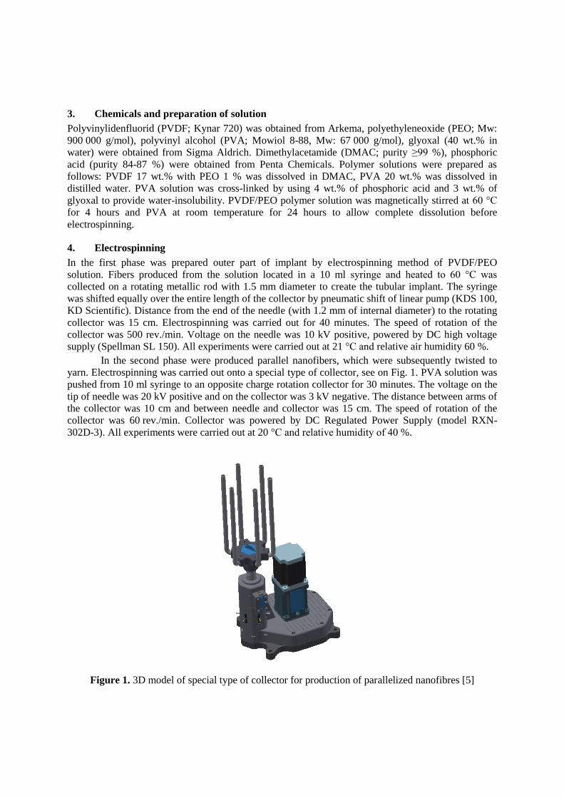
3. Chemicals and preparation of solution
Polyvinylidenfluorid (PVDF; Kynar 720) was obtained from Arkema, polyethyleneoxide (PEO; Mw:
900 000 g/mol), polyvinyl alcohol (PVA; Mowiol 8-88, Mw: 67 000 g/mol), glyoxal (40 wt.% in
water) were obtained from Sigma Aldrich. Dimethylacetamide (DMAC; purity ≥99 %), phosphoric
acid (purity 84-87 %) were obtained from Penta Chemicals. Polymer solutions were prepared as
follows: PVDF 17 wt.% with PEO 1 % was dissolved in DMAC, PVA 20 wt.% was dissolved in
distilled water. PVA solution was cross-linked by using 4 wt.% of phosphoric acid and 3 wt.% of
glyoxal to provide water-insolubility. PVDF/PEO polymer solution was magnetically stirred at 60 °C
for 4 hours and PVA at room temperature for 24 hours to allow complete dissolution before
electrospinning.
4. Electrospinning
In the first phase was prepared outer part of implant by electrospinning method of PVDF/PEO
solution. Fibers produced from the solution located in a 10 ml syringe and heated to 60 °C was
collected on a rotating metallic rod with 1.5 mm diameter to create the tubular implant. The syringe
was shifted equally over the entire length of the collector by pneumatic shift of linear pump (KDS 100,
KD Scientific). Distance from the end of the needle (with 1.2 mm of internal diameter) to the rotating
collector was 15 cm. Electrospinning was carried out for 40 minutes. The speed of rotation of the
collector was 500 rev./min. Voltage on the needle was 10 kV positive, powered by DC high voltage
supply (Spellman SL 150). All experiments were carried out at 21 °C and relative air humidity 60 %.
In the second phase were produced parallel nanofibers, which were subsequently twisted to
yarn. Electrospinning was carried out onto a special type of collector, see on Fig. 1. PVA solution was
pushed from 10 ml syringe to an opposite charge rotation collector for 30 minutes. The voltage on the
tip of needle was 20 kV positive and on the collector was 3 kV negative. The distance between arms of
the collector was 10 cm and between needle and collector was 15 cm. The speed of rotation of the
collector was 60 rev./min. Collector was powered by DC Regulated Power Supply (model RXN-
302D-3). All experiments were carried out at 20 °C and relative humidity of 40 %.
Figure 1. 3D model of special type of collector for production of parallelized nanofibres [5]

Into the tubular drain made of PVDF/PEO was inserted nanofiber yarn from PVA in various
numbers. This special prepared structure of PVDF/PEO implant with three nanofibrous yarns made
from PVA is shown on Fig. 2.
Figure 2. Composite fibrous drain composed of an outer PVDF/PEO channel and an inner PVA
nanofiber yarns; SEM microscopy, magnification 200x [6]
5. Characterization
Fibrous layers and yarns were studied by scanning electron microscopy (SEM; Tescan Vega 3SB Easy
Probe) and evaluated by software program NIS Elements AR 3.2. Images of fibrous layers are shown
in Fig. 3.
(a) (b)
Figure 3 Morphology of fibrous structures: (a) Outer part of drain made from PVDF/PEO in DMAC;
(b) inner part of 20 wt.% PVA in water. SEM microscopy, magnification: (a) 3.000x; (b) 1.000x
The average fiber diameter of PVDF/PEO was 930±275 nm and PVA was 263±99 nm. The
thickness of outer PVDF drain was 150 m and inner diameter was 1.5 mm. PVA nanofibrous yarns
were manually inserted into the PVDF channel.
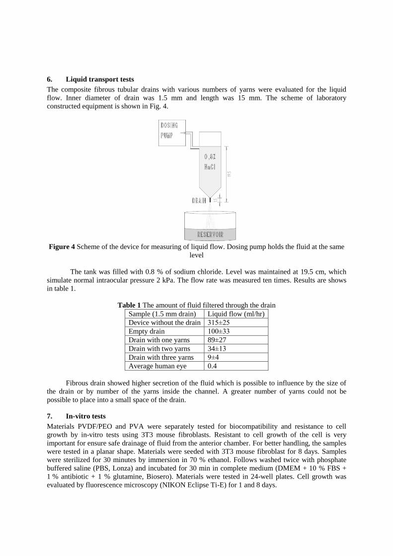
6. Liquid transport tests
The composite fibrous tubular drains with various numbers of yarns were evaluated for the liquid
flow. Inner diameter of drain was 1.5 mm and length was 15 mm. The scheme of laboratory
constructed equipment is shown in Fig. 4.
Figure 4 Scheme of the device for measuring of liquid flow. Dosing pump holds the fluid at the same
level
The tank was filled with 0.8 % of sodium chloride. Level was maintained at 19.5 cm, which
simulate normal intraocular pressure 2 kPa. The flow rate was measured ten times. Results are shows
in table 1.
Table 1 The amount of fluid filtered through the drain
Sample (1.5 mm drain) Liquid flow (ml/hr)
Device without the drain 315±25
Empty drain 100±33
Drain with one yarns 89±27
Drain with two yarns 34±13
Drain with three yarns 9±4
Average human eye 0.4
Fibrous drain showed higher secretion of the fluid which is possible to influence by the size of
the drain or by number of the yarns inside the channel. A greater number of yarns could not be
possible to place into a small space of the drain.
7. In-vitro tests
Materials PVDF/PEO and PVA were separately tested for biocompatibility and resistance to cell
growth by in-vitro tests using 3T3 mouse fibroblasts. Resistant to cell growth of the cell is very
important for ensure safe drainage of fluid from the anterior chamber. For better handling, the samples
were tested in a planar shape. Materials were seeded with 3T3 mouse fibroblast for 8 days. Samples
were sterilized for 30 minutes by immersion in 70 % ethanol. Follows washed twice with phosphate
buffered saline (PBS, Lonza) and incubated for 30 min in complete medium (DMEM + 10 % FBS +
1 % antibiotic + 1 % glutamine, Biosero). Materials were tested in 24-well plates. Cell growth was
evaluated by fluorescence microscopy (NIKON Eclipse Ti-E) for 1 and 8 days.

The cells on the materials were fixed by the frozen methanol and twice washed in PBS.
Samples were stained in the dark by DAPI, washed in PBS and again analysed by fluorescence
microscopy. Results are shown on the Fig. 5 a Fig. 6.
(a) (b)
Figure 5 PVDF/PEO images of fluorescence microscopy after staining of cell nuclei with DAPI
after 1 and 8 days of culture (magnification 10x): (a) PVDF/PEO after 1 day of cultivation; (b)
PVDF/PEO after 8 days of cultivation
(a) (b)
Figure 6 PVA images of fluorescence microscopy after staining of cell nuclei with DAPI after
1 and 8 days of culture (magnification 10x): (a) PVA after 1 day of cultivation; (b) PVA after
8 days of cultivation [6]
Materials made from combination of PVDF/PEO and made from PVA are biocompatible with 3T3
mouse fibroblasts and partially resistant to the growth of cells. Materials do not exhibit good adhesion
to the cells and does not exhibit cytotoxic effects on fibroblast cell line used. Materials appears to be
suitable for use in a place where it is necessary to resist against the cell growth.
Conclusions
Composite glaucoma fibrous tubular drain was created. This device is suitable for possible application
in the treatment of glaucoma. Electrospinning technology for production of the composite drain was
used. Materials were resistant to cell growth, which was confirmed by in-vitro tests. Liquid transport
tests through the drain confirm its filtration properties.
PVDF/PEO 1d PVDF/PEO 8d
PVA 1d PVA 8d

References [1] Soohoo JR, Seibold LK, Radcliffe NM and Kahook MY 2014 Minimally invasive glaucoma
surgery: current implants and future innovations Can J Ophthalmol 49 6 529–533
[2] Quigley HA and Broman AT 2006 The number of people with glaucoma worldwide in 2010
and 2020 Br J Ophthalmol 90 262–7.
[3] Hong CH, Arosemena A, Zurakowski D and Ayyala RS 2005 Glaucoma drainage devices:
A systematic literature review and current controversies Survey of Ophthalmol 50 1 48–60
[4] Subbiah T, Bhat GS, Tock RW, Pararneswaran S and Ramkumar SS 2005 Electrospinning of
nanofibers J Appl Polym Sci 96 557
[5] Shynkarenko A, Klapstova A, Krotov A Development of modified device for production of
parallelized nanofibres Nanocon 2015.
[6] Klapstova A, Vrsinska K, Horakova J, Saman A, Shynkarenko A, Lukas D 2016 Development
of fibrous implant for the treatment of glaucoma Nanocon 2016 ISBN 978-80-87294-71-0.
Acknowledgements The research was supported by the SGS - 21201 project for financial support and cooperation with
prof. David Lukas (KNT). We would also like to thanks Petr Bulir, the chiefs of the Department of
Ophthalmology at the Regional Hospital in Liberec.
Corresponding author: Andrea KLAPSTOVA
Technical University of Liberec, Faculty of Textile Engineering, Department of Nonwovens and
Nanofibrous Materials, Liberec 461 17, Czech Republic
E-mail: [email protected]

Combining material and structural elasticity – An approachto enhanced compliance of small-calibre vascular grafts
A Loewen1, K-M Kossel1, V Gesché1, T Gries1 and S Jockenhoevel1 2
1RWTH Aachen University, Institut für Textiltechnik of RWTH Aachen University,Department Biohybrid & Medical Textiles, Otto-Blumenthal-Str. 1, 52074 Aachen,Germany2RWTH Aachen University, Helmholtz-Institut für Biomedizinische Technik, Institutfür Angewandte Medizintechnik, Department Tissue Engineering & Biomaterials,Pauwelstr. 20, 52074 Aachen, Germany
Email: [email protected]
Abstract. Up to date, commercially available vascular grafts for the replacement of diseasedsmall calibre artery segments (d ≤ 6 mm) show low patency rates. One of the commonly namedcauses in literature is a low radial elasticity of the vascular graft, compared to that of the nativevessel. At the Institut für Textiltechnik of RWTH Aachen University, a new approachcombining elastic and non-elastic yarns in the warp knitting process is used for the productionof vascular grafts. This unique combination of material- and structural elasticity is used tobetter model the compliance of native vessels and thus increase the patency rates of syntheticvascular grafts.The first section in your paper
1. IntroductionCardiovascular diseases are the most common cause of death in developed countries as Germany [1].Today, several synthetic vascular grafts are commercially available for the treatment of diseasedarteries. All available grafts with a diameter of less than or equal to 6 mm show low long term patencyrates [2]. The compliance mismatch between the vascular graft and the native vessel is regarded to bea major cause of this issue (Fig. 1) [3].
The compliance describes the ability of a vessel to expand in radial direction when inner pressure isapplied. A low compliance of the vascular graft may cause an exceeding tissue growth within thelumen of the prosthesis (neointimal hyperplasia). This can lead to narrowing or even full occlusion ofthe graft related then with repeated surgery [5]. Psychological stress for the patient as well asconsiderable health economic costs are the consequences. At the same time, the demand for vasculargrafts steadily increases due to demographic change and unhealthy lifestyle especially within thewestern countries. Consequently, from 2005 till 2011 a constant growth of 3.8 % per year wasregistered in the European market for vascular grafts [6]. This shows the clear clinical need for aninnovative small calibre vascular graft with a significantly higher functionality than today's clinicalstandard.

Figure 1. Comparison of the compliance of native vessels and synthetic vascular grafts [4]
2. Research objective and approachThe mechanical properties of native blood vessels are decisively determined by their structure ofelastin and collagen fibres [7,8]. During the contraction phase of the heart, the so called systole, thepressure in the vascular system increases leading to strain in the arterial walls. The elastin fibres in thevascular wall bear the load within this pressure range. Due to its higher initial length and a windedstructure the collagen fibres are not elongated yet and do not significantly contribute to the mechanicalproperties of the vascular wall in this phase. At higher pressures the substantially stiffer collagen fibresare fully stretched and protect the vascular wall from overloading. During the ventricular filling of theheart, the diastole, the stretched fibres contract to their initial state. In consequence of these differingfunctionalities of the vessel’s components, arterial walls show a characteristic stress-strain curve(Fig. 2, left) [9].
Especially in the lower pressure range (20 – 80 mmHg) currently available vascular grafts have asignificantly lower compliance and do not cope with the characteristic stress-strain behaviour of nativevessels. This resulting compliance mismatch causes an exceeding tissue growth (neointimalhyperplasia) in the lumen of the synthetic vascular graft which leads to the reported constriction oreven an obstruction of the lumen.
Figure 2. Simplified representation of the mechanical structure of native vessels (left) and transfer ofthese physiological characteristics into a vascular graft combining material (TPU) and structural (warpknit) elasticity (right)
0
5
10
15
20
20 30 40 50 60 70 80 90 100 110 120 130 140
Com
plia
nce
[% /
100
mm
Hg]
Mean pressure [mmHg]
Native vesselWoven vascular graftExtruded vascular graft

At the Institut für Textiltechnik of RWTH Aachen University (ITA), a new approach incorporatingboth effects of material and structural elasticity in a vascular graft (ElaGraft) is proposed to model thestress-strain behaviour of native vessels. For this purpose, elastic and non-elastic yarns are combinedin the tubular fabric by use of warp knitting technology (Fig. 2, right).
In a first step, melt spun thermoplastic polyurethane (TPU) multi-filament fibres are developed.Due to its elastic properties combined with high hydrolytic and oxidative stability, a medical gradepolycarbonate urethane (PCU) is chosen for this purpose. The elastic TPU fibres are combined withnon-elastic PVDF fibres in a warp knitted tubular fabric. The desired mechanical properties of thetextile vascular graft are achieved by systematic variation and interaction of the melt spinningparameters and warp knitting parameters.
Tubular structures are manufactured on two double-face Raschel machines (DR 16 EEC/EAC andDJ 6/2 EL, Karl Mayer Textilmaschinenfabrik GmbH, Obertshausen, Germany) with gauges of 30 and32 needles per inch. The processed materials are thermoplastic polyurethane (TPU) for the elastic yarnand polyvinylidene fluoride (PVDF) for the non-elastic yarn. The counter-lapping 1x1 lap - 2x1 lap(locknit) has proven in the past to be suitable for elastic fabrics. This lapping combination is furtherfound in today’s synthetic vascular grafts and is therefore selected for the present project. The densityof the knitted fabric is tailorable by varying the stitch course density.
In order to ensure a stable process the elastic yarn has to be fed into the warp knitting machine at aconstant thread tension. Therefore yarn feeders, enabling a tension-controlled feed in of every TPU-yarn, were installed at the warp knitting machine. The yarn is fed directly into the knitting areawithout further deflection to avoid variations in tension.
The compliance of the produced synthetic grafts is experimentally determined and compared tonative vessels at physiological pressure. An enhancement of the compliance up to the characteristics ofnative vessels is aimed.
3. ResultsIn a first step, plain fabrics were produced to evaluate the process settings and their effect on thefabric’s mechanical properties. The stress-strain behaviour of the fabrics was determined in a tensiletest setup according to ISO 13934-1. By this means, the main influencing process parameters on theelastic properties of the fabric were determined. On the part of the melt spinning process, theseparameters are the wheel speed or take-up velocity and the draw ratio. On the side of the warp knittingprocess the main effecting parameters are the stitch course density and the thread tension of the TPUyarn.
Based on these results, tubular fabrics were produced by systematic variation of the influencingparameters. For this purpose, fractional and full factorial experiments based on the design ofexperiments method were performed to evaluate the resulting effects on the elastic properties of thevascular grafts. The stress-strain behaviour was determined in in a tensile test setup according to ISO13934-1 and converted into the radial compliance at a pressure of 30 mmHg. The results shownegative effects of the draw ratio and stitch course density (Fig. 3). These two effects are statisticallysignificant with a 95 % confidence level. The effects of the wheel speed and thread tension of the TPUyarn are not statistically significant and greyed in Fig. 3.

Figure 3. Main effect diagram for the target value "Compliance" at 30 mmHg
Due to the fact that a number of assumptions must be made to convert the stress-strain behaviourinto the compliance, the calculated values do not fully match the actual compliance values. Thus thecompliance of a vascular graft with low draw ratio yarn and low stitch course density was measuredwith a purpose-built setup according to ISO 7198. First results proved an enhancement of the actualradial compliance compared to current synthetic vascular grafts and native vessels (Fig. 4).
Figure 4. Comparison of the compliance of native vessels, synthetic vascular grafts and the ElaGraftapproach [4]
4. ConclusionBy incorporating material- and structural elasticity into a textile vascular graft, its mechanicalproperties can be specifically adjusted. By using warp knitting technology, the functional principle ofthe native vessel using elastin and collagen fibres can be transferred to a synthetic vascular graft byprocessing elastic (TPU) and non-elastic yarns (PVDF) and selecting the influencing manufacturingparameters. By this means, a significant improvement of the graft’s compliance compared to allsynthetic small-calibre vascular grafts in use is intended, following the major objective of increasing
1 10FS [cN]
p
1 3VS [-]
10
12
14
16
18
20
90 129WG [m/s]
8 14EAC [1/cm]
Com
plia
nce
[%/1
00m
mH
g]
Wheel speed[m/s]
Draw ratio[-]
Stitch coursedensity [1/cm]
Thread tension(TPU) [cN]
0
2
4
6
8
10
12
14
20 40 60 80 100 120 140
Com
plia
nce
[% /
100
mm
Hg]
Mean pressure [mmHg]
Native vessel
Woven vascular graft
Extruded vascular graft
ElaGraft

small calibre vascular grafts’ long term patency rates. This will result in offering a suitable alternativeto nowadays commercially available grafts.
References[1] Statistisches Bundesamt 2016 Leading causes of death in 2014.
https://www.destatis.de/EN/FactsFigures/SocietyState/Health/CausesDeath/CausesDeath.html
[2] Houis S, Deichmann T, Veit D and Gries T 2009 Medizinische Textilien Medizintechnik - LifeScience Engineering ed E Wintermantel and S W Ha (Berlin, Heidelberg: Springer-Verlag)p. 961-992
[3] Perea H, Methe H and Wintermantel E 2009 Magnetoseed - Vasculäres Tissue EngineeringMedizintechnik - Life Science Engineering ed E Wintermantel and S W Ha (Berlin,Heidelberg: Springer-Verlag) p. 513-547
[4] Deichmann T, Gesché V, Wöltje M, Rheinnecker M, Laar N, Gries T and Jockenhövel S. 2011Development of small-diameter vascular graft from biomimetic silk fibersProceedings FiberMed11: International Conference on Fibrous Products in Medical andHealth Care ed P Talvanmaa (Tampere, Finland)
[5] Abbott W M, Megerman J, Hasson J E, L'Italien G and Warnock D F 1987 Effect of compliancemismatch on vascular graft patency Journal of Vascular Surgery 5 p. 376-382
[6] MedTech Insight 2013 European Markets for Prosthetic Vascular Grafts, Report #A270[7] Hildebrand R 2010 Organe des Blutkreislaufs Anatomie ed K Zilles and B M Tillmann
(Heidelberg: Springer Verlag) p. 323-354[8] Deichmann T 2012 Prüf- und Bewertungsmethoden zur Charakterisierung textiler Implantate
für den Weichgewebeersatz (Aachen: Shaker Verlag)[9] How T V 1992 Mechanical properties of arteries and arterial grafts Cardiovascular biomaterials
ed G W Hastings (Berlin, Heidelberg, New York: Springer-Verlag) p. 1-37

Development of Electrospun Composite as Substitutive
Diaphragm Membrane
E Mohsenzadeh1, N Khenoussi
1, L Schacher
1, D Adolphe
1, J Hemmerlé
2, A
Schneider2, 3
, N Bahlouli4 and C Wagner-Kocher
1, 5 1Laboratory of Physics and Textile Mechanics, EA 4365 - UHA, Mulhouse, France 2National Institute of Health and Medical Research, UMR S 1121- INSERM,
Strasbourg, France 3Pediatric Surgery Department, University Hospital of Strasbourg, Strasbourg, France 4Laboratory of Engineering Science, data processing and imaging, UMR 7357 -
ICUBE, Strasbourg, France 5Mechanical and Civil Engineering Laboratory, Montpellier University, LMGC,
Montpellier, France
Email: [email protected]
Abstract. The diaphragm is the most important muscle for respiration with a bi-domed
structure, which is separating thoracic cavity from abdominal cavity. Partial formation of
diaphragm, with unknown reason during fetal development caused a birth defect called
congenital diaphragmatic hernia (CDH). It allows the abdomen contents to go up into the chest
cavity resulting in pulmonary hypoplasia, which is the major cause of the mortality. There are
several types of membrane, which can be used as prostheses to close the existing hole. In this
project, we study the tensile properties of electrospun PA-6 nanowebs and electrospun PA-6/B
composite as substitution membrane by a comparison with the tensile properties of tendon part
of pig’s diaphragm.
1. Introduction
The diaphragm is a layer of muscle and tendon that serves as the main part of respiration and plays a
vital role in the breathing process. Diaphragmatic hernia that occurs in about 1 in 5,000 live births, is
defined as congenital or acquired defect [1]. As the treatment, if the opening in the diaphragm is small
then it can be sewn. Otherwise, if it has a large size then the surgeon will require implanting an
additional tissue or membrane. Currently, Gore-Tex® (PTFE) as a synthetic biocompatible material is
used to patch this opening in University Hospital in Strasbourg/France (figure 1).
The problem is that Gore-Tex® implantable membrane is not elastic enough to follow the natural
growth of the child, so this patch usually requires replacement later by the child growth [2].
Figure 1. SEM images of double-faced current implanted Gore-Tex; a) Smooth surface b) Rough surface
a)
b)

Main objective of our study is to design a substitution membrane by electrospun nanofibers web.
Mechanical properties of substitutive membrane have to be close to the human diaphragm that have
been represented by pig’s diaphragm in this study.
2. Materials and Methods
2.1. Uniaxial Tensile Test on: Pig’s Diaphragm, electrospun PA-6 nanofibers and electrospun PA-6/B
composite
The insufficiency of data on mechanical behaviour of human soft tissue is firstly because of the
difficulty of obtaining human tissues for testing and secondly because of the lack of the standard
testing technics for mechanical testing of soft tissues [3]. For this reason, we performed some
mechanical tests on pig’s diaphragm (withdrawn from University Hospital, Strasbourg/France), which
is the most feasible, and the nearest case to simulate the human one.
Diaphragm is contained of dense collagen fibres, arranged diagonally from lateral to medial
direction.
Therefor pig’s samples were excised from different parts of diaphragm from the left and right side,
vertically and horizontally based on the tendon fiber orientation (figure 2).
Figure 2. Sampling from the fresh pig’s diaphragm, left and right part
Soft tissue and electrospun samples have been placed between special frames using pneumatic
gripes before being tested. A velocity of 10 mm/min and gripes distance of 15 mm are set on MTS
machine for all the tested samples by following ISO 527-3 standard. A temperature controller
chamber (Instron 3119.005) was mounted to the MTS tensile machine to keep the temperature
stable at 37°C (human body temperature). To reduce the slippage of the samples between the
gripes, which was challenging during the tensile test one-side sandpaper frame with waterproof
backing which the samples were stitched to them was used.
2.2. Electrospinning of PA-6 electrospun nanofibers and PA-6/B composite
PA-6 was chosen as a polymer to produce electrospun nanoweb because of its biocompatibility and
expected adequate mechanical properties. Different electrospinning conditions have been tested by
using a vertical homemade electrospinning booth to obtain optimal conditions of producing PA-6
nanofibers. To improve the strain properties of electrospun PA-6 nanofibers, a thin layer of elastomer
material (material B) was used while electrospinning of PA-6 solution. Electrospinning time was
varied: 15, 30, 60, 90 minutes. Electrospun nanofibers were observed via SEM micrographs and
diameters were measured thanks to ImageJ software.
3. Results and discussion
Mechanically, tendon works as a force transmitter during rapid muscle contraction. A basic similarity
is considered in the structure and function of most tendons. Tendon shows a non-linear behaviour in

uniaxial tension. Once a load is applied (toe region of load- strain curve), the fibres start stretching
parallel to the load direction. As the load further increases, the collagen fibres reorient in order to carry
a greater proportion of load. By continuing to increase the load, a transition from low to high stiffness
occurs and is known as the strain stiffening effect where the fibres will be over stretched and begin to
rupture until the failure happens [4].
The specimens, slipped from any of the grippes, were not included in the results. The tensile curves
of two tendon samples of right (R10: cut vertically and the R2: cut according to the tendon
direction) and left (L7: cut vertically and L1: cut according to the tendon direction) side of the
diaphragm are shown in figure 3 a and b.
Figure 3. Load-strain % curves of right side (a) and left side (b) of pig’s diaphragm
The interval of maximum load between 7 and 18 N as well as the interval of strain between 27 and
50 percent are obtained by testing different numbers of samples from right side of diaphragm.
Load-Strain % curves of the left side samples revealed the interval of maximum load between 8
and 23 N and strain between 15 and 53 percent.
To produce electrospun PA-6 nanofibers, 20 wt. % solution of PA-6/Formic acid with 0.1 mL/h
feed rate was injected to the needle by applying 30 kV of voltage between needle and collector
with a distance of 15 cm. In figure 4, the SEM micrograph of electrospun PA6 nanofibers after 15
minutes electrospinning is presented.
Figure 4. SEM image of 15 minutes electrospun PA-6 nanofibers
30 single nanofibers diameter were randomly measured by ImageJ software. The SEM micrograph
displays the nanofibers with an average diameter of 184 nm.
Tensile test results on shorter time of spinning of electrospun PA-6 nanofibers shows improved
mechanical properties. By increasing electrospinning duration on material B (after 30 minutes of
electrospinning), delamination has been observed between two layers leading us to conclude that
shorter time of electrospinning on material B is more favourable (figure 5).
a) b)

Figure 5. Delamination between material B and Electrospun PA-6 nanofibers
A comparison between tensile results of 15 minutes electrospun PA-6 and electrospun PA-6/B
composite is demonstrated in figure 6.
Figure 6. Comparison load-strain % curves of 15 minutes electrospun PA-6 and electrospun PA-6/B composite
Electrospun PA-6/B composite displays more deformation for example for the load of 2 N compared
to electrospun PA-6 nanofibers web with the same time of electrospinning.
4. Conclusion
The mechanical tests confirmed that regardless of the sampling region, the pork’s diaphragm presented
isotropic properties. For the optimum electrospinning conditions, an average diameter of 184 nm
without defects was obtained. It was also observed that by increasing the time of electrospinning, the
rupture force of the sample increased but the strain decreased. Moreover, an important increase of the
electrospinning time, led to a total loss of the elasticity of elastomer material and delamination was
occurred.
References
[1] Rehan V K, Laipraset J, Wallach M, Rubin L P and McCool F D diaphragm dimensions of the
healthy preterm infant 1999 Pediatric Research 45 317A
[2] Schneider A, Koob M, Sananes N, Senger B, Hemmerlé J and Becmeur F computed
tomographic study of the pediatric diaphragmatic growth: Application to the treatment of
congenital diaphragmatic hernia 2016 European Journal of Pediatric Surgery 27(02) 177-
180
[3] Gaur P, Chawla A, Verma K, Mukherjee S, Lalvani S, Malhotra R and Mayer C
characterisation of human diaphragm at high strain rate loading 2016 Journal of the
mechanical behavior of biomedical materials 60 603-616
[4] Evans J H and Barbenel J C structural and mechanical properties of tendon related to function
1975 Equine veterinary journal 7(1) 1-8

Textile structures from hyaluronan based core-shell fibers
T Pitucha1,2, K Lipenska1, J Kubickova1, V Zapotocky1,3 and V Velebny1 1Contipro a. s., Dolni Dobrouc 401, Czech Republic 2Technical University of Liberec, Faculty of Textile Engineering, Department of
Textile Technologies, Studentska 2, 461 17 Liberec, Czech Republic [email protected] 3Charles University, Third Faculty of Medicine, Department of Medical Biophysics and
Informatics, Ruska 87, 100 00 Prague 10, Czech Republic
Abstract. Core-shell fibers based on the combination of soluble and insoluble types of
hyaluronan were successfully created using wet-spinning method. High swelling of the fibers in
synergy with tight textile structures were employed to ensure release of the dissolved fiber core
through local cracks in the fiber shell. Thanks to the biocompatibility and resorbability of
hyaluronan, the braided or knitted textile structures made from these fibers have a potential to
be employed as a drug carrier in medical applications.
1. Introduction
Hyaluronic acid (HA) or briefly hyaluronan is a natural polysaccharide composed of D-glucuronic acid
and N-acetylglucosamine. It is contained in the human body, e.g. in extracellular matrix, synovial fluid,
eyes and skin. Thanks to its biocompatibility and biodegradability, HA is commonly used in cosmetic
and pharmacy [1,2]. Hyaluronan can have various forms suitable for different medical applications, e.g.
hydrogels for tissue engineering and viscous solutions or freeze-dried layers for wound healing. Also
fibers and textiles based on hyaluronan derivatives has been already developed and utilized in surgery
to improve tissue regeneration [3,4]. A fabrication of the textile scaffold based on hydrophobized HA
was reported in another paper [5]. Because hyaluronan is not a meltable polymer the fibers thereof can
be formed just using a solution spinning process.
Hyaluronan in its natural form is soluble in water but using a chemical modification an insoluble
variant can be obtained. This can be advantageous in various medical applications in which a prolonged
stability of the fibers in a tissue is required. Anyway, such modified fibers still swell a lot when dipped
in a water-based medium, including various body fluids, e.g. blood, wound exudate or saliva. A wet-
spinning process that allows the formation of hyaluronan-based monofilaments has been invented in
Contipro [6,7]. This process is suitable both for the natural HA and for its hydrophobized derivatives.
The aim of our consequent work was to develop a fibrous system utilizable as a carrier of active
substances in medical applications. The basic idea was to create a bicomponent fiber comprising of two
different derivatives of hyaluronan arranged separately as a core and shell of the fiber. It was expected
that native hyaluronan which is soluble in water would carry an active substance whereas an insoluble
derivative of hyaluronan would ensure mechanical compactness of the fiber in wet conditions.
An extensive effort was made to obtain fibers with sufficient tensile properties and flexibility which
would allow them to be processed by textile techniques like knitting or braiding to create a fabric.
Within textile structures (woven, knitted, braided) yarns are mutually interlaced and touch each other
in cross points. The geometry of the yarn axis relates to the fabric pattern, the yarn diameter and the

tightness of the textile structure. If fibers within the yarns shrink and/or swell when dipped in water the
fabric gets closer and tighter which results in the fabric shrinkage. This phenomenon has been studied
in the relation with washing of cotton fabrics [8]. Anyway, if the fiber swelling and/or shrinkage is much
higher than in case of cotton then these dimensional changes can cause enormous tensile stress in the
fibers and result in their break.
As mentioned above a critical property of hyaluronan-based fibers is their huge swelling in a water-
based medium. Therefore, this study is focused not only on the properties of the HA-based core-shell
fibers in the dry state but also on the behavior of the textile structures when they interact with water.
2. Materials and Methods
2.1. Hyaluronan and its derivatives
A range of hyaluronan based polymers of Contipro production was used for manufacturing of the core-
shell fibers. The water-soluble variant of hyaluronan was sodium hyaluronate (SH) of molecular weight
(Mw) of 1,6 MDa. The insoluble variants included HA derivatives (HA-der) acylated by fatty acids
(palmitic, oleic, stearic) with different degree of substitution (DS).
2.2. Spinning process
The core-shell fibers were created by extrusion of two different polymer solutions through a two-way
coaxial spinneret to a coagulation bath. In some cases, the spinning solution contained a functional agent,
e.g. iron oxide nanoparticles (NP) or a drug (octenidine dihydrochloride). Various process parameters
incl. concentrations of the spinning solutions, extrusion rate and up-winding speed were used to obtain
fibers of different fineness and ratio between the core and shell components. Finally, the fibers were
scoured in ethanol to remove residues of the coagulation bath and dried at room temperature.
2.3. Fiber fineness and geometry
The fiber fineness was determined by weighting of fiber segments of 1 m length. The geometry of fibers
was studied by scanning electron microscopy (SEM) using the microscopes Tescan VEGA II LSU and
ZEISS Ultra Plus and by optical microscopy (Nicon Eclipse Ci-L). Ratio between the core and shell
fiber component was calculated from the concentrations of the spinning solutions and their extrusion
rates. Swelling properties were determined by dipping of fibers in demineralized water and measuring
their diameter.
2.4. Tensile test
The tensile strength and the elongation at break were measured on the dynamometer Instron 3343. The
measurement was executed at 23±2 °C and relative humidity of 50±5 %. The test length was 100 mm
and the elongation rate was 30 mm·min-1.
2.5. Textile technologies
2.5.1. Braiding. The horizontal braiding machine Steeger HS 80/48 VEA was used to produce a tube
from 16 monofilaments interlaced in the twill pattern. Two variants of the tube were made:
a) A tube with a hollow inside
b) A tube with a steel wire of 0.5 mm diameter additionally inserted into the hollow
The braiding density of both tubes was 13 picks/cm, braiding angle 30° and the outer diameter 1.25 mm.
2.5.2. Knitting. The raschel machine Comez DNB-EL of gauge 12 was employed to prepare a narrow
strip of single-faced tricot patterned fabric with the closed loops. The loop density was:
a) 4 wales/cm, 5 courses/cm
b) 5 wales/cm, 7 courses/cm

3. Results and discussion
3.1. Fiber morphology
The HA based core-shell fibers have a form of monofilaments with an irregular shape of cross section
which is caused by the coagulation process and the consequent drying (see the figure 1). The fineness
of such fibers is in the range of 10 to 40 tex which corresponds with the diameters of 100 to 300 µm
(despite the non-circular cross-section of fibers the term diameter is used in this paper and it means
thickness of an individual fiber). The ratio between the core and shell components is between 1:1 to 1:5.
Determination of the boundary between the core and shell on the cross section can be sometimes difficult
when using SEM. Alternatively it can be detected using optical microscopy thanks to different optical
properties of SH and HA-der or if a colored agent (e.g. NP) is incorporated in the fiber core.
Examples of the HA based core shell fibers and their properties are listed in the table 1.
(a) (b)
Figure 1. Morphology of the core-shell fiber based on hyaluronan: (a) cross section of the fiber (scale
bar 20 µm) (b) longitudinal view (scale bar 100 µm).
3.2. Mechanical properties and processability
The tensile strength of the fibers is between 0,05 and 0,1 N/tex which is lower than most of the
conventional fibers. The mechanical properties of the HA based fibers strongly depend on the air
humidity: if the humidity is low the fibers get brittle and tend to break when processed. The fibers have
quite high bending rigidity thanks to their high diameter which complicates their processability too.
Thus, gentle mechanical conditions and appropriate air humidity (50-60%) must be ensured during
mechanical processes like knitting or braiding.
Table 1. Examples of the hyaluronan based core-shell fibers.
Core Shell Core-shell
ratio
Fineness
[tex]
Strength
[N]
Breaking
elongation [%]
SH der-HA 1:3.5 19 1.46 12.3
SH der-HA + NP 1:5.0 32 2.62 8.1
SH der-HA + drug 1:2.5 20 1.97 15.4
der-HA der-HA 1:2.0 20 1.11 9.5

3.3. Fiber swelling
When the core shell fiber is dipped in water both the core and shell absorb a lot of the liquid. The SH
core begins to dissolve whereas the insoluble HA-der shell just swells. The difference between the dry
fiber and the swollen fiber is shown in the figure 2. The swelling rate is quite high: the fiber diameter
can increase more than thrice within several minutes as documented in the figure 3. This swelling results
in the pressure on the core; if the fiber is dipped completely including its cut ends the dissolved SH is
pushed out of the core towards the fiber ends. The core works like a hose and a pump in the same time
which results in spilling the core out of the shell part.
The fiber swelling depends on the liquid media, on the selected variant of the HA derivative and on
the degree of substitution. As the degree of substitution increases the fiber swelling decreases.
(a) (b)
Figure 2. HA based core-shell fiber containing nanoparticles in the soluble core: (a) in the dry state
and (b) in the swollen state after dipping in water (scale bars 500 µm).
Figure 3. Swelling of the HA based core-shell fiber after dipping in demineralized water: Changes of
the fiber diameter in dependence on the time.
0
100
200
300
400
500
600
700
0 1 2 3 4 5 6
fiber
dia
met
er [µm]
dipping time [min]

3.4. Shell ruptures and core release
The huge increase of the fiber diameter causes significant changes of the textile structure. As the fibers
swells a textile structure gets tighter and a free space between fibers decreases. Moreover, the swollen
core-shell fibers press to each other in cross points. We could see that in some cases the mutual pressure
in the cross points resulted in the shell disruption. Anyway, the fibers did not break fully but just local
cracks were created randomly at different places of the textile so that the textile structure remained
compact. The local shell ruptures of the fibers within a braided and knitted textile can be seen in the
figure 4. It seems that the cracks often arise in places where the fiber is bended over a neighbouring one.
(a) (b)
Figure 4. Ruptures of the shell part of the fibers arisen from swelling: (a) a rupture in the cross point
of the braided tube (b) a rupture in the cross point of the knitted fabric (scale bars 100 µm).
The cracks in the fiber shell allow the dissolved fiber core to spill out of the fiber. This phenomenon
is shown in the figure 5: Swelling of the fibers within a braided tube resulted in local shell ruptures. The
places where the core spills out can be seen thanks to the brownish color of the nanoparticles contained
in the fiber core. The ruptures only arose on the variant with the wire inserted inside the tube. In the
other case (with the hollow inside) the pressure between the fibers were not so high to disrupt the fiber
shell probably because the inner segments of the swollen fibers could deflect to the free space inside the
tube. Disruptions of the fiber shell followed by spilling of the core were observed also at knitted fabrics.
(a) (b)
Figure 5. Braided tube from HA based core-shell fibers with nanoparticles in their core: (a) dry state
(b) swollen state – spilling of the dissolved core is visible as brownish smudges (scale bars 1000 µm).

3.5. Possibilities of the controlled drug release
Based on our preliminary experiments we know that various drugs can be incorporated into the fiber
core. We suppose that the above described “rupture effect” and the consequent spilling of the dissolved
core can be utilized for the controlled drug release: in the dry conditions the fibers would hold a drug
inside but as soon as the fabric gets in contact with a body fluid (e.g. blood or wound exudate) the drug
release would be ensured via the spilling the liquid core through the cracks caused by swelling.
The inception of the rupture effect and the progress of the core spilling can be influenced by the fiber
composition and by the textile structure. The most important factors will be the hydrophobicity of the
fiber shell (DS of the HA derivative), core-shell ratio, way of the fiber interlacement (braided, knitted,
woven) and the density of the textile (warp and weft density of woven fabrics, course and wale density
of knitted fabrics, braiding density and braiding angle on braids). Optimization of these parameters is
one of the tasks for the future research and development of the HA based core-shell fiber systems for
medical purposes.
4. Conclusion
Core-shell fibers based on the combination of the soluble and insoluble type of hyaluronan were
successfully created using wet-spinning method and further processed by conventional textile
technologies. When the fibers are dipped in water they swell significantly and if the textile structure is
tight enough then the swollen fibers press to each other in cross points which causes local ruptures. In
case the shell is from the insoluble HA and the core from the soluble HA the dissolved core can spill
out from the core through these cracks. We expect that such rupture effect can be utilized as a trigger
for releasing a drug incorporated in the fiber core after the textile structure gets in contact with a body
fluid e.g. at bleeding. Braided or knitted textile structures made from these fibers have a potential to be
employed as a drug carrier in medical applications.
References
[1] Collins M N 2014 Hyaluronic Acid for Biomedical and Pharmaceutical Applications
(Shawsbury, Shrewsbury, Shropshire: Smithers Rapra)
[2] Selyanin M A, Boykov P Y Khabarov V N 2015 Hyaluronic Acid. Preparation, Properties,
Application in Biology and Medicine (Chichester: Wiley)
[3] Esenyel C Z et al. 2014 Surgical Treatment of the Neglected Achilles Tendon Rupture with
Hyalonect J. Am. Podiatr. Med. Assoc. 104/5 434-443
[4] Mermerkaya M U et al. 2016 Scintigraphic evaluation of the osteoblastic activity of rabbit tibial
defects after HYAFF11 membrane application J. Orthop. Surg. Res. 11:57
[5] Zapotocky V et al. 2017 Fabrication of biodegradable textile scaffold based on hydrophobized
hyaluronic acid Int. J. Biol. Macrom. 95 903-909.
[6] Betak J et al. 2014 Endless fibres on the basis of hyaluronan selectively oxidized in the position
6 of the n-acetyl-d-glucosamine group (PCT Int. Appl., WO 2014082610 A1)
[7] Scudlova J et al. 2014 Fibres based on hydrophobized derivatives of hyaluronan, method of their
preparation and use, textiles on base thereof and use thereof (PCT Int. Appl., WO 2014082611
A1)
[8] Suh M W 1967 A study of the shrinkage of plain knitted cotton fabric, based on the structural
changes of the loop geometry due to yarn swelling and deswelling Tex. Res. J. 37 417-431

The Potential of Improving Medical Textile for CutaneousDiseases
C D Radu1, A Cerempei1 M Salariu1 O Parteni1 E Ulea2 and Chr Campagne3,4
1”Gh.Asachi” Technical University Iasi, Faculty of Textile, Leather and Industrial Management,angeron 29 Iasi Romania,2 “I. Ionescu Brad” University of Agricultural Sciences and Veterinary Medicine, Aleea MSadoveanu street, 3, Iasi,3 Univ. Lille Nord de France, F-59000 Lille, France;4 ENSAIT, GEMTEX, F-59100 Roubaix, France;
E-mail: [email protected]
Abstract. The paper dwells on the prospect of medical textiles designed to release a drug/activeprinciple to the dermis of patients suffering from cutaneous disease (allergic dermatitis, psoriasis,bacterial/infectious conditions and inflammatory conditions). The paper is an overview of generaland experimental data from textile applications. An adequate medical textile may have a cellulosicstructure, mainly knitted cotton fabric. In special cases, one may use woven fabric for multilayerdrug-releasing systems. As far as controlled release systems are concerned, we carried out acritical comparison between the systems described in literature and our experimental findings asconcerns cyclodextrin, hydrogel, film charged with active principles and multilayer system.
1.IntroductionMedical textiles are worn by the patient directly against the skin as socks, pajama top and bottom,underpants, undershirt, gloves; these are knitted 100% cotton items with interlock structure, which formsa temporary drug deposit on the textile surface; the action of skin-specific factors (perspiration, skinenzymes, friction, etc.) trigger drug release and support drug diffusion to the dermis. The quantity of drugapplied on the fabric is equivalent to the therapeutic dose.
The medication involved in textile applications cures allergic and infectious dermatitis and burns, aswell as chronic conditions like psoriasis, venous failure and skin cancer.
Medical textiles are designed for patients who are active individuals and have neither the time, nor theconditions for topical therapy (a private room at work where they could expose the skin where theointment needs to be applied), or for patient who forget to take their medication and prefer using drug-releasing textile items, which allow continuous therapy without the patient’s active and consciouscontribution. Thus, one may use either a disposable textile fabric, or a regular textile fabric, which is drugrecharged after use.

Ideally, the kinetics of drug release to the dermis should constantly range between the lower and uppertherapeutic limits, as shown in Figure 1, curve 2. It is the dermatologist who sets the therapeutic range.Curve 1 in Figure 1 illustrates the kinetics of the release of a drug manifesting a “burst effect”. Anydeviation from the therapeutic dose impairs treatment efficacy. Thus, the CD section of curve 1 illustratesthe case of administration of a smaller amount of drug than the lower limit, whereas the AB section ofcurve 1 shows that when too much drug is released to the skin, i.e. when drug diffusion exceeds the upperlimit, this increases drug toxicity. The so-called “burst effect”, which is an unwanted drug releasemanifestation, is well known [1]. It is detected in CD and hydrogels, and it consists of sudden drugrelease, i.e. of making available more than 60% of the total amount of drug required for disease therapy.
Figure 1. Setting the drug release range
2. Drug release systems. Development potential and therapeutic limitsThe following release systems may be used on a textile structure: cyclodextrins, hydrogels, multilayersystems, polymer matrix, liposomes, Ringsdorf’s conjugate polymer-drug systems, etc. Among these,applications of drugs on textile fabric for cyclodextrins, hydrogels, multilayer systems and polymermatrices have been described so far.
2.1. Cyclodextrin-based drug encapsulation and release systemCyclodextrins (CD) have been known for a long time (1891), yet their applicative potential wasdiscovered, assessed and used in recent years [1]. CD products are available as: alpha-, beta- and gamma-CD and their derivatives. There are synthesized products with reactivity to cotton or wool, such asmonochlorotriazinyl-beta-CD, which is grafted by 1st order nucleophilic substitution in basic environmentconditions (NaOH), at temperatures ranging between 160 and 180oC, by the pad-dry-cure procedure. Theuse of CD to store the drug in the interstices of a textile item and its release has raised considerableinterest proven by the high number papers on this topic, which have been written lately.
CD may form complexes inside the hydrophobic cavity with lipophilic drugs or only with thelipophilic sections of a pharmacodynamic principle. This is no drawback, since most pharmaceuticalproducts are lipophilic. The restriction is the result of the limitation in size of the hydrophobic section ofthe drug [2], which should range between 7.8 Å (CD cone height) and 6.5 Å (inner diameter of the CDcavity). Another limitation is the fact that, upon the in vitro release of the drug, which occurs in theperspiration kit [3], for a specific dermis pH of 5.5, the kinetic behavior has a “burst effect”. Anotherdeficiency is the coarse surface of the textile fabric. The solution would be the use of a biocompatibleemollient. The use of active phytosanitary principles (alcoholic Viola Tricoloris Herba and Menthapiperita extract) or of active apicultural principles (alcoholic propolis extract) for an antiallergenictherapy determines an emollient effect, which compensates the CD action [4].
CD were used for the release of an anti-inflammatory agent (Naproxen) [5], of an antifungal agent(Terbinafine) [5] or of an antibiotic (Ciprofloxacin) [6,7]. Metals (silver) and metal salts, quaternary

ammonium compounds, polyhexamethylene biguanide, etc. are used as antibacterial agents deposited intextile fabrics [1]. The use of CD on woolen items for antibacterial therapy was reported when silvernanoparticles and Triclosan were employed as active principle. A chitosan matrix, in which Geraniumessential oil (aqueous Pelargonium graveolens extract) was incorporated, was used as release system in acotton woven fabric [8]. Staphylococcus aureus and Escherichia coli were used for the biological tests.
Citric acid-grafted beta-CD was used for antibacterial action on 100% cotton woven fabric, in order toincrease the Ag storage capacity, which is lower in the procedure that does not involve citric acid [9].Miconazole nitrate (antifungal agent), forming monochlorotriazinyl-beta-CD complexes, was used oncotton woven fabric [10]. A pajama made of 100% cotton interlock knitted fabric with 60/1 fineness wasused for atopic allergy therapy [4]. Monochlorotriazinyl-beta-CD was grafted inside the pajama usingmenthol, Viola Tricoloris Herba, propolis as alcoholic solution and hydrocortisone acetate. The biologicaltests were conducted using Chaetomium spirale, Aspergillus wentii and Aspergillus niger, which areallergy-inducing microorganisms. Another study used tacrolimus (antiallergic and antipsoriatic agent)[11], which formed 2,6-di-O-methyl-CD complexes. -66 polyamide and Lycra (polyurethane) stockingswere created for contention therapy and phlebotonic release for patients suffering from chronic venousfailure (varices) [12].
2.2. Hydrogel-based drug release systemHydrogels are solid systems consisting of polymer chains able to bind water by hydrogen bounds, thusstoring a temporary water and drug deposit; unlike other structures, water sorption determinesconsiderable swelling. The swelling capacity of polymer networks is due to functional groups interactingwith water and it is limited by network reticulation frequency [13]. The drug transferred from thehydrogels applied to a textile structure makes up diffusion controlled systems; the transfer phenomenonoccurs both at macroscopic scale and through the tridimensional network of the hydrogel-specificpolymer network. The systems are applicable especially to high potency drugs, since their skin diffusiongradient and application surface are limited, and drug concentrations change the skin pH of that area andmay cause skin discomfort.
A comparative study [14] was conducted on hydrocortisone acetate release from chitosan hydrogel andfrom monochlorotriazinyl-beta-CD (Figure 2).
Figure 2. Comparative kinetics of hydrocortisone acetate release from CD-graftedknitted fabric and from hydrogel-impregnated knitted fabric
The findings in Figure 2 show a “burst effect” on hydrocortisone acetate release from both CDderivative and chitosan hydrogel. The Korsmeyer-Peppas model [15] in the equation hereunder (1) is usedto model the release characteristics of an active principle.
Mt/Mequilibrium = K x tn (1)where: Mt is the amount of hydrocortisone acetate released over a “t” period; Mequilibrium is the amount ofhydrocortisone acetate released on equilibrium, K a constant and n the release exponent. As far as the CD
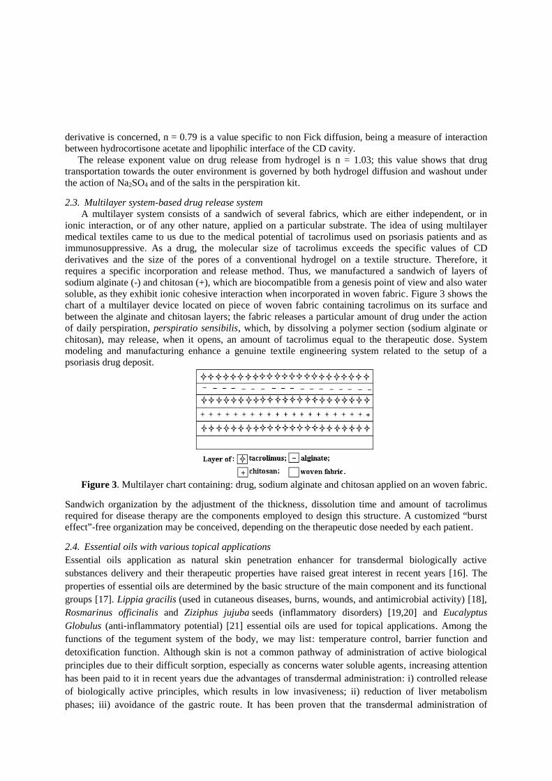
derivative is concerned, n = 0.79 is a value specific to non Fick diffusion, being a measure of interactionbetween hydrocortisone acetate and lipophilic interface of the CD cavity.
The release exponent value on drug release from hydrogel is n = 1.03; this value shows that drugtransportation towards the outer environment is governed by both hydrogel diffusion and washout underthe action of Na2SO4 and of the salts in the perspiration kit.
2.3. Multilayer system-based drug release systemA multilayer system consists of a sandwich of several fabrics, which are either independent, or in
ionic interaction, or of any other nature, applied on a particular substrate. The idea of using multilayermedical textiles came to us due to the medical potential of tacrolimus used on psoriasis patients and asimmunosuppressive. As a drug, the molecular size of tacrolimus exceeds the specific values of CDderivatives and the size of the pores of a conventional hydrogel on a textile structure. Therefore, itrequires a specific incorporation and release method. Thus, we manufactured a sandwich of layers ofsodium alginate (-) and chitosan (+), which are biocompatible from a genesis point of view and also watersoluble, as they exhibit ionic cohesive interaction when incorporated in woven fabric. Figure 3 shows thechart of a multilayer device located on piece of woven fabric containing tacrolimus on its surface andbetween the alginate and chitosan layers; the fabric releases a particular amount of drug under the actionof daily perspiration, perspiratio sensibilis, which, by dissolving a polymer section (sodium alginate orchitosan), may release, when it opens, an amount of tacrolimus equal to the therapeutic dose. Systemmodeling and manufacturing enhance a genuine textile engineering system related to the setup of apsoriasis drug deposit.
Figure 3. Multilayer chart containing: drug, sodium alginate and chitosan applied on an woven fabric.
Sandwich organization by the adjustment of the thickness, dissolution time and amount of tacrolimusrequired for disease therapy are the components employed to design this structure. A customized “bursteffect”-free organization may be conceived, depending on the therapeutic dose needed by each patient.
2.4. Essential oils with various topical applicationsEssential oils application as natural skin penetration enhancer for transdermal biologically activesubstances delivery and their therapeutic properties have raised great interest in recent years [16]. Theproperties of essential oils are determined by the basic structure of the main component and its functionalgroups [17]. Lippia gracilis (used in cutaneous diseases, burns, wounds, and antimicrobial activity) [18],Rosmarinus officinalis and Ziziphus jujuba seeds (inflammatory disorders) [19,20] and EucalyptusGlobulus (anti‐inflammatory potential) [21] essential oils are used for topical applications. Among thefunctions of the tegument system of the body, we may list: temperature control, barrier function anddetoxification function. Although skin is not a common pathway of administration of active biologicalprinciples due to their difficult sorption, especially as concerns water soluble agents, increasing attentionhas been paid to it in recent years due the advantages of transdermal administration: i) controlled releaseof biologically active principles, which results in low invasiveness; ii) reduction of liver metabolismphases; iii) avoidance of the gastric route. It has been proven that the transdermal administration of

biologically active compounds required for efficient skin penetration is done by diffusion, through theepidermal appendages, thus avoiding the barrier constituted by the stratum corneum or the transdermallayer. The administration of biologically active compounds through epidermal transappendages includestheir penetrating into the body through the sweat glands and hair follicles (Figure 4). This method is lesscommonly used due to the rather small administration area. The transappendageal route is preferred fornanoparticle transportation due to their size. The transepidermal route is the most commonly used route ofbiologically active principle administration. Thus, the biologically active compound molecules maypenetrate the transcellular (lipids and corneocytes) şi intercellular (lipids) stratum corneum [22].
Figure 4. Biologically active compound administration routes
The drawback of transdermal systems consists of the fact that the skin only allows biological compoundswith rather small molecules (800-1,000 Daltons) to pass [23]. Given their size that does not exceed 800Daltons and their fat soluble structure, essential oils are adequate for topical applications.
2.4.1. Topical applications of essential oilsDifferent systems incorporating essential oils have been used to prevent their degradation under the actionof environmental factors (oxygen, light and temperature). In addition to protection against externalfactors, essential oil incorporation also ensures their lengthy controlled release [24].Here are the most frequently used controlled release systems of essential oils [25]: chitosan-basedhydrogels; soil-gel siloxane matrices (rigid network with pores smaller than one micrometer and polymerchains with average lengths exceeding one micrometer); carbon nanotubes (allotropes of carbon withcylindrical structure); cyclodextrins. Figure 5 shows how essential oils are applied by incorporating themin the chitosan matrix.
Figure 5. Essential oil incorporation in the polymer matrix

The essential oil release mechanism from the biodegradable polymer matrix is a combination betweendiffusion controlled release and chemically controlled release. Essential oil molecule migration in theouter environment occurs through the matrix micropores. The diffusion process is controlled by thesolubility and permeability of the essential oil in/through the chitosan matrix. Biologically activecompound diffusion on the polymer matrix surface and active compound transportation on its surface arethe essential oil release stages from the chitosan matrix.
3. Discussions and conclusionsThe amount of current knowledge, some of which was referred to in our paper, allows considering areassensitive to controlled release for acute or chronic dermatological therapies, which require in-depthapproaches, enhancements and solutions for a release profile ranging strictly between the lower and uppertherapeutic limits.
The most promising method is the use of CD, due to their biocompatibility and adjustment tolipophilic molecules with average molecular mass, just like many of the pharmaceutical products.
The establishment of valuable active principles belonging to phytosanitary skin therapies, which areless dependent on weather conditions and the components of which have reasonable variability when usedfor skin diseases, would help set up a wider therapeutic basis.
Going beyond the stratum corneum and hypodermal barrier would mean an expansion of thesetherapies towards the systemic area, as well as the extension of the therapeutic uses of drug-releasingmedical textiles.
REFERENCES[1] Radu C, Parteni O and Ochiuz L 2016 J. Control. Release 224 146[2] Messner M, Kurkov S V, Jansook P and Loftsson T 2010 Int. J.Pharm.. 387 199[3] Kultong K et al 2010 Part. Fibre Toxicol. 7 1[4] Radu C et al 2013 Carbohydr. Polym. 95 479[5] Machin R, Isasi J R and Velaz I 2012 Carbohydr. Polym. 87 2024[6] Blanchemain N et al 2011 Acta Biomater. 7 304[7] Blanchemain N et al 2012 Carbohydr. Polym. 90 1695[8] Cerempei A, Muresan E and Cimpoesu N 2014 J Esent. Oil Res. 26 267[9] Bajpai M, Gupta P and Bajpai S 2010 Fibers Polym.. 11 8[10] Wang J H and Cai Z 2008 Carbohydr. Polym. 72 695[11] Uekama K 2002 J. Incl. Phenom. Macrocycl. Chem. 44 3[12] Nichifor M et al 2009 J. Mater. Sci. Mater. Med., 20 975[13] Verestiuc L and Tanase C E 2011 Biodegradable Polymers for controlled release of drugs (Medical
Applications of polymers vol 2) ed M Popa, R M Ottenbrite and V C Uglea (California: AmericanScientific Publishers) chapter 7 pp 318-330
[14] Parteni O 2015 Ph.D.Thesis ”Gheorghe Asachi” Technical University Iași pp 74-89[15] Mahat B S 2009 Mathematical models used in drug release studies, Department of Pharmacy School of
Science Kathmandu Nepal pp 29-32[16] Edris AE 2007 Phytother. Res. 21 308[17] Marqués-Calvoa MS, Codony F, Agustí G and Lahera C 2017 Photodiagnosis Photodyn Ther 17 180[18] Riella KR et al 2012 J Ethnopharmacol 143 656[19] Al-Reza SM et al 2010 Food Chem Toxicol 48 639[20] Altinier G et al 2007 J. Agric. Food Chem. 55 1718[21] Reuter J, Huyke C et al 2002 N Engl J Med 347 13[22] Montenegro L et al 2016 J Drug Deliv Sci Technol 32 100[23] Vilceanu N and Popescu M 2015 Practica Farmaceutica 8 29[24] Martín Á et al 2010 The Open Chemical Engineering Journal 4 31[25] Rogobete A et al 2014 Romanian Journal of Anaesthesia and Intensive Care 21 53
Production of yarns composed of oriented nanofibers for ophthalmological implants
A Shynkarenko1, A Klapstova2 , A Krotov1, M Moucka1 and D Lukas2 1Technical University of Liberec, Faculty Of Mechanical Engineering, Department of manufacturing systems and automation, Studentská 1402/2, 461 17 Liberec 1, Czech Republic 2Technical University of Liberec, Textile Faculty, Department of Nonwovens and Nanofibrous Materials, Studentská 1402/2, 461 17 Liberec 1, Czech Republic E-mail: [email protected]
Abstract. Parallelized nanofibrous structures are commonly used in medical sector, especially for the ophthalmological implants. In this research self-fabricated device is tested for improved collection and twisting of the parallel nanofibers. Previously manual techniques are used to collect the nanofibers and then twist is given, where as in our device different parameters can be optimized to obtained parallel nanofibers and further twisting can be given. The device is used to bring automation to the technique of achieving parallel fibrous structures for medical applications.
1. Introduction Glaucoma diseases is the worldwide problem in ophthalmology. The progression of this disease leads to permanent blindness. Statistics show that more than 60 million people worldwide suffer from this disease[1,2].These problem can be eliminated by nanofibrous tubular shape for drain of fluid [3]. The main goal of the produced yarn is to ensure the incompressibility of the structure and safe drainage of fluid from the patient's eye due to this oriented structure.
In this article the parameters of self-fabricated device that allows the fabrication of a nanofibrous yarn are described. The main idea of this device is full automation of the process of manufacturing a nanofiber thread. And also to improve the accuracy of the manufacturing by avoiding the operation that was previously done manually.
2. Previous experience Device for production of nanofibres parallelized structures has been previously constructed in cooperation with Clemson University in South Carolina, USA [4]. This device was modified at Technical University of Liberec and enables the production of nanofibres yarns with the different rotating collectors and the electrostatic forces. The improved device enables the production of higher quality oriented structures from multiple materials. Results of the work were presented in the articles [5,6]. But that device was a first step in production of a nanofiber yarn.
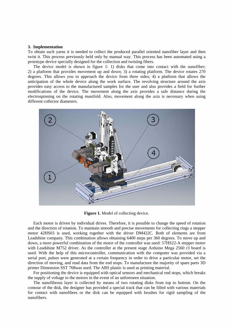
3. Implementation To obtain such yarns it is needed to collect the produced parallel oriented nanofiber layer and then twist it. This process previously held only by manual way. This process has been automated using a prototype device specially designed for the collection and twisting fibers.
The device model is shown in figure 1: 1) disks that come into contact with the nanofiber; 2) a platform that provides movement up and down; 3) a rotating platform. The device rotates 270 degrees. This allows you to approach the device from three sides; 4) a platform that allows the anticipation of the whole device along the work surface. The revolving structure around the axis provides easy access to the manufactured samples for the user and also provides a field for further modifications of the device. The movement along the axis provides a safe distance during the electrospinning on the rotating manifold. Also, movement along the axis is necessary when using different collector diameters.
Figure 1. Model of collecting device.
Each motor is driven by individual drives. Therefore, it is possible to change the speed of rotation and the direction of rotation. To maintain smooth and precise movements for collecting rings a stepper motor 42HS03 is used, working together with the driver DM422C. Both of elements are from Leadshine company. This combination allows obtaining 6400 steps per 360 degrees. To move up and down, a more powerful combination of the motor of the controller was used: 57HS22-A stepper motor with Leadshine M752 driver. As the controller at the present stage Arduino Mega 2560 r3 board is used. With the help of this microcontroller, communication with the computer was provided via a serial port, pulses were generated at a certain frequency in order to drive a particular motor, set the direction of moving, and read data from the end stops. To manufacture the majority of spare parts 3D printer Dimension SST 768was used. The ABS plastic is used as printing material.
For positioning the device is equipped with optical sensors and mechanical end stops, which breaks the supply of voltage to the motors in the event of an unforeseen situation.
The nanofibrous layer is collected by means of two rotating disks from top to bottom. On the contour of the disk, the designer has provided a special track that can be filled with various materials for contact with nanofibres or the disk can be equipped with brushes for rigid sampling of the nanofibers.

And also, depending on the diameter of the discs and the physical properties of the nanomaterial, when twisting, it is necessary to shorten the distance between the disks in order to control the tension of the thread and avoid a rupture. The assembly of the rotary collector and the collecting device is shown on a figure 2.
Figure 2. The assembly of the rotary collector and the collecting device.
There are a lot of parameters to change in the device. Therefore, the microcontrollers have been programmed in such a way as to receive and transmit the variables responsible for the speed of rotation of the collecting discs, the speed of movement of the device along the axes, the direction of movement, and the like on the serial port to a computer on which the user can easily operate with these parameters.
4. Experiment Functional prototype was tested in the laboratory using the followingmaterials. Polyvinylidenfluorid (PVDF; Mw: 180 000 g/mol) and polyethyleneoxide (PEO; Mw: 900 000 g/mol) obtained from Sigma Aldrich. Dimethylacetamide (DMAC; purity ≥99%), was obtained from Penta Chemicals. Polymer solution was prepared as follows: PEO 1wt.% and PVDF 16,7wt.% were dissolved in DMAC at 60°C. This material was chosen for the reason that it has very good elastic mechanical properties. The polymer solution was magnetically stirred for 4 hours at 60°C to allow complete dissolution before electrospinning. Electrospinning was carried out also at 60°C. The polymer solution was heated using a special device for heating the solution in the syringe. Solution was pushed from syringe to an opposite charge rotation collector for ca. 20 minutes. The voltage on the tip of needle was 15kV positive and on the collector was 4kV negative. The distance between needle and collector was 15 cm and the distance between arms of the collector was 10 cm. The speed of rotation of the collector was 50 rev./min. Collector was powered by DC Regulated Power Supply (model RXN-302D-3). All experiments were carried out at 21°C and relative humidity of 60%.
The collection of nanofibers from a rotating collector can occur in two ways. The difference is in the impact of collective discs on the collector and their rotation speed. Two types of collection are presented in the scheme shown on figure 3. In the first case (figure 3a), prefabricated disks barely

touch the canvas with nanofibers and move along the crooked arrow downward. The speed of rotation of the disks corresponds to the rate of descent downward. Thus, the circumference of the disk as if passes through the surface of the nanofibrous canvas. In the second case, the assembly discs run to the collector as much as possible, as depicted on Figure 3b. The direction of rotation of the assembly discs remains the same (clockwise), but the rotation speed decreases. This is done in order to increase the density of the material that is collected, as there is an assumption that the resulting material after such a collection method has a higher percentage of parallel fibers in its structure.
(a) (b)
Figure 3. Two ways of collecting nanofibers. 1. Rotating collector; 2. Collecting disks.
In our experiment, the first method of collection was used. All the obtained samples are prepared for liquid transport testing.
5. Results Figure 4 shows the results of operation of the device.
(a) (b)
Figure 4. Results of operation of the device: a) gathered nanofibrous from rotating collector; b) twisted nanofibrous
The topology of collected nanofibrous yarns was studied by scanning electron microscopy (SEM;
Tescan Vega 3SB Easy Probe). Fibers were sputter coated by 7 nm of gold. Fiber morphology evaluation was carried out by software program NIS Elements AR 3.2. Images of nanofibrous layers are shown in figure 5. Fiber diameter of produced yarn was 980±120 nm.

(a) (b)
Figure 5. SEM microscopy of produced nanofibrous yarn made from PEO/PVDF: (a) magnification 1.000x (b) magnification 5.000x
6. Conclusions The functional prototype showed very promising results for future research in nanofiber yarns production from parallelized nanofiber structures. Yarns are made from combination of PEO and PVDF polymer solution showed good mechanical properties. They are elastic and have required form. One of the main benefit of the devise is the possibility to change parameters of gathering and twisting the fibrous. This option will be useful for further experiments. Also a lot of different polymer solutions will be tested in future.
7. Acknowledgments This publication was written at the Technical University of Liberec as part of the project SGS21183 with the support of the Specific University Research Grant, as provided by the Ministry of Education, Youth and Sports of the Czech Republic in the year 2017.
Also we express our gratitude Prof. RNDr. David LukášCSc. and Ing. Michal Moučka, Ph.D. for assisting in the development of the device.
References [1] Quigley H A 2011 Glaucoma J. Lancet p 1367-77 [2] Gabelt B T and Kaufman P L 2005 Changes in aqueous humor dynamics with age and
glaucoma J. Proress in Retinal Eye Reearch 24(5) p 612-637 [3] Klapstova A and Mikes P 2015 Nanofiber Drain for Glaucoma Drainage Implants Proc. Int.
Conf. NART (Liberec: Technical University of Liberec) [4] Tsai ChCh, Mikes P, Andrukh T and others 2011 Nanoporous artificial proboscis for probing
minute amount of liquids Nanoscale 3(11) p 4685-95 [5] Shynkarenko A, Klapstova A and Krotov A 2015 Development of Device for Parallel
Structured Nanofibers Yarns Production Proc. Int. Conf. NANOCON 2015 (Brno) [6] Shynkarenko A, Klapstova A and Lukas D 2016 Comparison of the collecting heads efficacy
using electrospinning method Proc. Int. Conf. NANOCON 2016 (Brno)