Embed Size (px)
Citation preview

International Journal of Advancements in Research & Technology, Volume 5, Issue 12, December-2016 - 112 - ISSN 2278-7763
Effect of Soil Stiffness on Impact Resistance of
Concrete Plate
1Msc. Zainab Hassan Shakir, 2Msc. Sura Amoori Abbas 1, 2 Dept. of Civil Engineering (Building and Construction Engineering)
University of Technology, Iraq, Baghdad [email protected]
[email protected] Abstract- Most structures are designed to carry their own weights in addition to certain superimposed loads which considered being static loads. In fact, no structural loads (with the exception of dead loads) are really static, since they have to take a certain time interval to be applied to the structure. Any time varying loads may be considered as a dynamic load. In this study, nonlinear three-dimensional finite element analysis has been used to conduct a numerical investigation of the effect of applied impact load on the foundation based on sandy soil using the finite element method by ANSYS (Version 11) computer program. The 8-node brick elements are used to represent the concrete foundation and the soil under the foundation which are denoted by Solid 65 for concrete and Solid
45 for the soil. The interface is modeled by using three-dimensional surface-to-surface (Target 170 and Contact 174) contact elements connected with concrete and soil. As a case study, a concrete foundation with dimensions (3×3×0.3) m placed on the foundation soil (15 m) deep and (9 m) away from the edge of plate is subjected to eccentrically applied impact load. Three values for foundation thickness are chosen (0.3, 0.5, and 0.75) m to investigate their effect on the analysis results, these values are checked to maintain the foundation requirements under static loads. The study includes investigating the effect of impact load eccentricity variation on vertical displacement and vertical stress.
Keywords: Soil Stiffness, Impact Resistance, Concrete Plate.
Introduction
Plates on elastic foundation are often used in civil engineering problems, such as building infrastructures, tanks or silo foundations, aerospace engineering, etc. [1]. Plates are commonly used as structural elements and are subjected to a wide variety of static and dynamic loads. Broadly, the dynamic loads can be classified into three major categories:
Steady state harmonic loads as in the case of machine foundations and structures supporting rotating machines.
Random loads as in the case of seismic excitation on tall buildings, wind induced loads on slender structures or wave loads on offshore structures.
Impulsive or shock loads as in the case of hammer foundations, missile impact, blast loads on structures or an aircraft crashing against a civil engineering structure. The term 'impact' covers a wide range of topics that are of great interest to do the research work. The dynamic response to impact is complex and is dependent on many factors such as velocity of the striker, size of the striker, contact area at the impact zone, size of the target structure, material behavior of the target structure and the striker, etc.
IJOART

International Journal of Advancements in Research & Technology, Volume 5, Issue 12, December-2016 113 ISSN 2278-7763
Copyright © 2016 SciResPub. IJOART
Beam and Plate on Elastic Foundation Most of the previous work began with the well known Winkler model which was originally developed for the analysis of railroad tracks. The use of the Winkler model involves one major problem and one significant
behavioral inconsistency. The problem involves the necessity for determining the modulus of subgrade reaction, "kz", and the behavioral inconsistency is that an analysis of plates carrying a uniformly distributed load will produce a rigid body displacement [2].
Beam on elastic foundation There are many applications for beams on elastic foundation in civil engineering, e. g., vibrating machines on elastic foundations, network of beams in the construction of floor systems for ships, buildings, bridges, submerged floating tunnels, buried pipelines, railroad tracks, etc. The elastic foundation for the beam part is supplied by the resilience of the adjoining portions of a continuous elastic structure [3]. Beams on elastic foundations received great attention of researches due to its wide applications in engineering. Hetenyi (1946) and Timoshenko (1956) presented analytical solutions for beams on elastic supports using classical differential equation approach and considering several loading and boundary conditions. It is well known in engineering that a beam supported by discrete elastic supports spaced at equal intervals acts analogously to a beam on an elastic foundation, and that the appropriateness of that analogy depends on the flexural rigidity of the beam as well as the stiffness and spacing of the supports. Ellington (1957) investigated the conditions under which a beam on discrete elastic supports could be treated as equivalent to a beam on elastic foundation.
Beams resting on elastic foundations have been studied extensively over the years due to the wide application of this system in engineering. This system according to the literature can be divided at least into three categories [4].The first category is “linear beam on linear elastic foundation”. The applications in this category include but are not limited to Euler -Bernoulli beam, Timoshenko beam, Winkler foundation, Pasternak foundation, tensionless foundation, single-parameter or two-parameter foundation, static loading, harmonic loading and moving loading. The second category is “linear beam on nonlinear elastic foundation”. In this category, the foundation is considered to have nonlinear stiffness. Also, this type includes different boundary and loading conditions according to the engineering application. The third category is nonlinear beam on linear elastic foundation. Usually, the beam nonlinearity means large deflections. Most of the studies related to this category have analyzed the system either using boundary element method or boundary integral equation method. Similar to the above two categories, there is a wide variety of boundary and loading nonlinear beams subjected to harmonic distributed load resting on linear elastic foundation.
. Plate on elastic foundation Plates on elastic foundations have received considerable attention due to their wide applicability in civil engineering. Since the interaction between structural foundations and supporting soil has a great importance in many engineering applications, a considerable amount of research has been conducted on plates on elastic foundations. Much research has
been conducted to deal with bending and vibration problems of beam and plates on elastic foundation. Many studies have been done to find a convenient representation of physical behavior of a real structural component supported on a foundation. The usual approach in formulating problems of beams, plates, and shells continuously supported by elastic media is based on the inclusion of the foundation reaction in the corresponding differential equation of the beam, plate, or shell [5].
Types of Dynamic Loads The foundations are generally excited by any of the following loads [6]:
Impact loads. Unbalanced rotating and reciprocating parts
of the machines which produce transient and steady state dynamic loads.
Neighborhood of vibration environment.
Earthquakes. Wind-induced forces. Other periodic and periodic forces and
moments, such as those due to blasting,
IJOART

International Journal of Advancements in Research & Technology, Volume 5, Issue 12, December-2016 114 ISSN 2278-7763
Copyright © 2016 SciResPub. IJOART
mining, drilling and piling operations and sonic booms.
Moving load.
Numerical and finite element methods Malter (1960) considered two numerical methods for the solution of beams on elastic foundations. The first was based on Newmark method which is a step – by – step integration process. The second, using finite difference equations to determine the vertical deflection directly and then the contact pressure. Malter found that the second method requires less time than the first [7]. Emrich et.al. (1982) used the finite element method to investigate the behavior of reinforced concrete beams subjected to impact load. Nonlinear constitutive laws for concrete and steel were assumed. Newmark implicit time scheme was used to solve nonlinear dynamic equations. A consistent mass matrix was used; neither structural nor material damping was considered. Results were verified by results from experiments and were in a good agreement [8]. Hinton (1988) analyzed reinforced concrete plates and shells under dynamic loading. Three dimensional isoparametric brick elements with 20 nodes were used to simulate the concrete. A modified elastic-plastic constitutive model was adopted to represent the concrete behavior. Newmark implicit time scheme was used to solve nonlinear dynamic equations. Results were compared with other models and were found in a good agreement [9]. Miyamoto et.al. (1991) used Dracker-Prager to model concrete when they investigate the analytical and numerical failure modes of reinforced concrete slabs subjected to impulse loads. They examined the rate of dynamic load, the maximum deflection in the center, and the impulse load-midspan deflection curves from zero to ultimate load, the propagation of cracks through the cross section, and the pattern at failure. The numerical failure mode was determined as well as the load rating in failure mode and the distribution of cracking while they carried out a comprehensive study in this field. They could not simulate the steel reinforcement under the impact loading, the density of cracking in the critical region, and the complete failure process from crushing in the compression zone to cracking in the tensile region [10]. Jayasuriya (1992) studied a modified two-parameter Vlasov foundation model developed for the dynamic analysis of a finite circular plate resting on an elastic foundation. The load was considered as a triangular
impact which simulates the falling weight deflectometer blows. The application of the developed model in the impact loading analysis was illustrated with the numerical results obtained, and the results were compared with the records of the field test results. A parametric study was conducted for different elastic properties of the elastic foundation and thicknesses of the plate. The results were obtained for the variation of properties and behavior during the course of impact loading and after the impact diminished [11]. Tameroglu (1996) studied a different solution technique for free vibrations of rectangular plates with clamped boundaries resting on elastic foundations and subjected to uniform and constant compressive, unidirectional forces in the mid- plane. The method was based on the use of a non-orthogonal series expansion consisting of some specially chosen trigonometric functions for the deflection surface (w) of the plate. The orthogonalization of the series and other calculations were performed using Fourier expansion of Bernoulli polynomials under some realistic approximations for the limiting values of the boundary conditions. It was concluded that by this method, one does not need to use the solution of the differential equation of the problem. The results obtained for the problem were consistent with the well-known solutions [12]. Saha (1997) studied the dynamic stability of a rectangular plate on an elastic foundation subjected to uniform dynamic loads and supported on completely elastically restrained boundaries. The non-homogeneous foundation consisted of two regions having different stiffnesses but symmetric about the center lines of the plate. The equation governing the small amplitude motion of the system was derived by a variation method. The effects of stiffness and geometry of the foundation were also studied in addition to boundary conditions, static load factor, in-plane load ratio and aspect ratio on the stability boundaries of the plate for first- and second-order simple and combination resonance [13]. Karsin (2004) studied the exact stiffness, geometric stiffness and consistent mass matrices of the beam element on two-parameter elastic foundation extended to solve plate problems. Some examples of circular and rectangular plates on two-parameter elastic foundation, including bending, buckling and
IJOART
International Journal of Advancements in Research & Technology, Volume 5, Issue 12, December-2016 115 ISSN 2278-7763
Copyright © 2016 SciResPub. IJOART
free vibration problems were solved by the finite grid solution. Comparison with known analytical solutions and other numerical solutions showed a good agreement with results [14]. Celep and Guler (2004) studied the static behavior and forced oscillations of a rigid circular plate supported by a tensionless Winkler elastic foundation by assuming that the plate is subjected to a uniformly distributed load and a vertical load having an eccentricity. It was observed that the lift-off had a significant effect on the motion of the plate, the recognizable period of the oscillations is lengthened and the amplitudes become larger, because the tensionless foundation model is relatively less constrained compared to the conventional one[15]. Tee (2005) studied the dynamic response of a finite circular plate resting on sand by using ABAQUS program. In the analysis, a free-drop impact system was considered to generate the dynamic loading on the plate free surface. Two finite element models were built, one with a slide line underneath the target plate and another one without the slide line. The numerical results of the finite element method for the radial strain at the bottom of the target plate were compared with the experimental measurement. The numerical results showed a good agreement with the experimental results [16]. Sun et.al. (2005) studied the beam responses under an impact nondestructive testing load using the Fourier and Laplace transforms. Numerical computation was performed for a parametric study of beam and load parameters. It was shown that under an impact load, the time duration for displacement to vanish was ten times longer than that for velocity and acceleration. The maximum response was achieved first in acceleration, followed by velocity, and finally displacement, all of which occur before the impact load is removed [17]. Muslih (2007) studied the behavior of rectangular slabs with different boundary conditions and subjected to impact loading caused by falling mass. The model slabs were of dimensions (500 x 500 x 20) mm, and the independent variables were the falling mass, the height of drop and the deformation constant. Also, the effects of moment of inertia were discussed. Theoretical analysis based on the numerical solution of the slab impact integral equation was carried out to determine the impact force and deflection time histories, the strain energy absorbed by the slabs and the maximum bending moment. The
effect of slab boundary conditions on the impact response of slab was also discussed. The theoretical results obtained from the analysis were compared with the experimental and theoretical works previously done, and showed a good agreement with the experimental results [18]. Kasim (2006) studied the nonlinear dynamic analysis of reinforced concrete slabs using the finite element method. Impact and blast loading were considered. Eight-node serendipity degenerated elements were employed. Geometric nonlinearities were considered in the analysis, based on the total Lagrangian approach accounting or large deformations in von Karman sense. Several computer programs coded in FORTRAN language were used. These programs were arranged to give a complete listing of stress and deformation in every concrete or steel layer at any time. Various reinforced concrete beams and slabs were analyzed under dynamic loading. A good agreement was found by comparison of the obtained results with available test results and other related studies [19]. Shaban et.al. (2010) carried out free vibration and modal stress analyses of thin circular plates with arbitrary edge conditions, resting on two-parameter elastic foundations. Both Pasternak and Winkler parameters were adopted to model the elastic foundation. The differential transform method was used to solve the eigenvalue equation yielding the natural frequencies and mode shapes of the circular plates. The accuracy of obtained results was evaluated by comparing the results with those available in the well-known references. Furthermore, effects of the foundation stiffness parameters and the edge conditions on the natural frequencies, mode shapes, and distribution of the maximum in-plane modal stresses were investigated [20]. Borgerhoff et.al. (2011) presented the analyses of impact tests of reinforced concrete slabs with dominating punching behavior and confirmed that the layered shell element of the program SOFiSTiK was suitable for a reliable numerical simulation of the problem, provided that the slabs had a minimum of transverse reinforcement, which was sufficient to assure that the ultimate limit state with respect to punching is not exceeded. The requirement was the implicitly fulfilled in the design of a structure which has to resist a specified impact load. In the case of checking reinforced concrete plates without shear reinforcement (or with significant exceedance of
IJOART
International Journal of Advancements in Research & Technology, Volume 5, Issue 12, December-2016 116 ISSN 2278-7763
Copyright © 2016 SciResPub. IJOART
punching resistance), empirical perforation formulae or analyses by use of simple two-mass vibration models are applicable [21]. Mahmoudpour et.al. (2011) presented a coupled scaled boundary finite element model to examine the dynamic response of a structure considering the soil-structure interaction. The analysis was performed in time domain. The material behavior of soil and structure was assumed to be linear. They reported
that when the system was subjected to sine excitation, the reduction in displacement and base shear was more significant when the loading frequency was close to natural frequencies of the structure. The reduction in displacement and base shear was more significant for the second mode than the first one, thus considering SSI in dynamic analysis of the structure affects the higher modes more significantly[22].
Factors Controlling Design of Machine Foundations The most important parameters for the design of machine foundation are the operating frequency of the machine, the natural frequency of the foundation soil system and the amplitude of vibration of the machine at its operating frequency. One of the key steps in current methods of dynamic analysis of a foundation soil system to predict the resonant frequency and amplitude under dynamic loading is to estimate the stiffness and damping of the foundation soil system. Based on the assumptions that foundation is a rigid body attached to the surface of an elastic half-space, many investigators presented the stiffness and damping factors for the foundation considering various modes of vibration, various contact stress distributions, displacement conditions and various shapes and sizes. Several theories have been proposed for the design of machine foundations resting on soils that idealize soils
as homogeneous elastic half -spaces. In reality, however, soils are rarely homogeneous. The soil in the natural strata can exist in a state consisting of a hard rock at shallow depth and consisting of different soil layers having different properties. All these methods are based on approximations and assumptions and, therefore, a considerable engineering judgment is required to take into account the several parameters affecting it. It is well established that stiffness of the foundation soil system depends on several factors, namely initial static stress, magnitude of dynamic stress increment, the distribution of stresses over the contact area, variation of shear modulus with depth, layering in the soil medium, embedment of footing, etc. Hence, the nature of dynamic loads and non-homogeneity of soil make the analysis and design of foundation subjected to dynamic loads more complex (Thangaraj and Ilamparuthi, 2010).
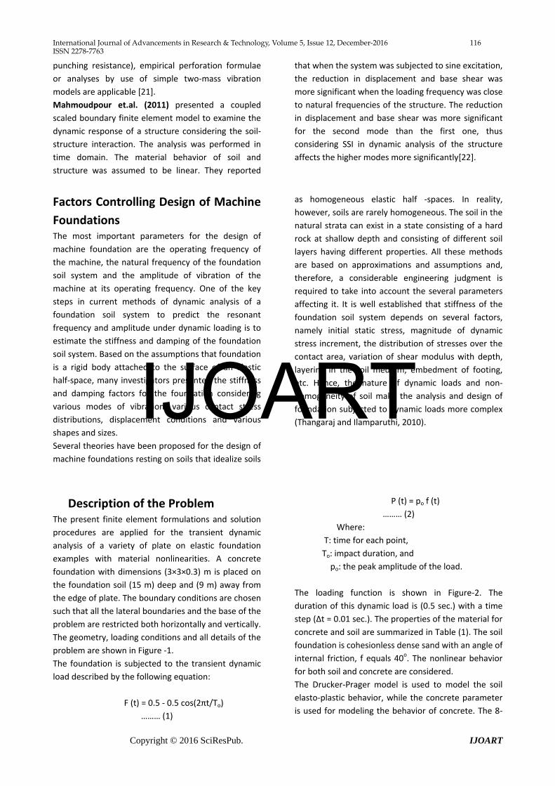
Description of the Problem The present finite element formulations and solution procedures are applied for the transient dynamic analysis of a variety of plate on elastic foundation examples with material nonlinearities. A concrete foundation with dimensions (3×3×0.3) m is placed on the foundation soil (15 m) deep and (9 m) away from the edge of plate. The boundary conditions are chosen such that all the lateral boundaries and the base of the problem are restricted both horizontally and vertically. The geometry, loading conditions and all details of the problem are shown in Figure -1. The foundation is subjected to the transient dynamic load described by the following equation:
F (t) = 0.5 - 0.5 cos(2πt/To)
……… (1)
P (t) = po f (t) ……… (2)
Where: T: time for each point, To: impact duration, and
po: the peak amplitude of the load.
The loading function is shown in Figure-2. The duration of this dynamic load is (0.5 sec.) with a time step (Δt = 0.01 sec.). The properties of the material for concrete and soil are summarized in Table (1). The soil foundation is cohesionless dense sand with an angle of internal friction, f equals 40o. The nonlinear behavior for both soil and concrete are considered. The Drucker-Prager model is used to model the soil elasto-plastic behavior, while the concrete parameter is used for modeling the behavior of concrete. The 8-
IJOART
International Journal of Advancements in Research & Technology, Volume 5, Issue 12, December-2016 117 ISSN 2278-7763
Copyright © 2016 SciResPub. IJOART
node brick elements in ANSYS are used to represent the concrete of Foundation and the soil under the foundation which are denoted by Solid 65 for concrete and Solid 45 for
the soil and the interface elements are modeled by using three-dimensional surface-to-surface (Target 170 and Contact 174) contact elements connected with concrete and soil.
a) Three-dimensional finite element model.
b) The finite elements mesh for the solid model
(ANSYS Manual V11, 2007).
Fig.1: Typical finite element mesh.
IJOART

International Journal of Advancements in Research & Technology, Volume 5, Issue 12, December-2016 118 ISSN 2278-7763
Copyright © 2016 SciResPub. IJOART
Fig.2: the loading function.
Table (1) Material properties for concrete and soil in the basic problem.
Concrete
Symbol Definition Value
f′c Compressive strength (MPa) 25
cE Young’s modulus (MPa) 23500
Tensile strength (MPa) 3.1
Ν Poisson’s ratio 0.15*
ρc Density (kg/m3) 2400
Interface µ Coefficient of friction 0.6*
Soil
Es Young’s modulus (MPa) 50
cu Cohesion 0
Φ Frication angle 40o
Ν Poisson’s ratio 0.3*
ρs Density (kg/m3) 1800
Notes: *Assumed value, cE = 4700 f c′ and = 0.62 f c′
IJOART

International Journal of Advancements in Research & Technology, Volume 5, Issue 12, December-2016 119 ISSN 2278-7763
Copyright © 2016 SciResPub. IJOART
Effect of elastic modulus and strength of soil The effect of modulus of elasticity for soil is studied in this section. The impact load amplitude is changed to different values (25, 75 and 100) kN. Three values for modulus of elasticity are used (Es=50, 20, 10) MPa with (B=3 m, L=3 m, t=0.3 m). These values of elastic modulus correspond to dense sand, medium and loose sand respectively. The corresponding values of the soil
angle of internal friction ( are 40o, 36o and 32o, respectively. Figures (3) to (6) clarify the effect of the modulus of elasticity for soil on the vertical displacement and vertical stress, and it can be seen that: For amplitude loads (p = 25, 75 and 100) kN, when the modulus of elasticity for soil decreases from (Es= 50 to 20 and 10) MPa, the maximum vertical displacement at node (81) at the center of foundation increases by about (14.0 and 18.9) %, respectively. On the other hand, the decrease in the modulus of elasticity for soil from (Es=50 to 20 and 10) MPa leads to decrease in the maximum vertical stress at node (81) depending on the amplitude of load by about (0.1 and 6.4) %, respectively. From Figures (3) to (7), it can be noted that when the amplitude of loads increases from (25 to 75 and 100) kN, the maximum vertical displacement and stress for modulus of elasticity for soil (10 to 20 and 50) MPa will increase.
From Figure (4 a), the maximum vertical displacement takes place at time (0.24 sec.) for modulus of elasticity soil (10 MPa) and amplitude loads (25, 75 and 100) kN, while the maximum vertical displacement occurs at time (0.26 sec.) for the modulus of elasticity of soil (20 MPa) and the same amplitude loads, Figure (5 a). This leads to a conclusion that the increase of soil stiffness decays the propagation of stress wave within the foundation. From Figure (6 a), the maximum vertical stress takes place at time (0.37 sec.) for modulus of elasticity of soil (10 MPa) and amplitude loads (25, 75 and 100) kN, while the maximum vertical stress occurs at time (0.21 sec.) for modulus of elasticity soil (20 MPa) and the same amplitude loads, Figure (7 a). From above figures, it can be observed that decreasing of the modulus of elasticity results in increasing the maximum displacement and reducing the maximum stress. The greater modulus of elasticity means that the soil is stiffer, i.e. the soil will experience less amount of settlement. The results for this case are similar to those obtained for modulus of elasticity of the soil (50 MPa). Maximum vertical stress and displacement are smaller because the geometry of foundation, especially its thickness, makes its behavior as a rigid foundation. The foundation carried most of the applied loading and small loading is carried by the soil
IJOART

International Journal of Advancements in Research & Technology, Volume 5, Issue 12, December-2016 120 ISSN 2278-7763
Copyright © 2016 SciResPub. IJOART
a) at node 81 (center of foundation) b) along section a-a (for amplitude 25 kN)
c) along section a-a (for amplitude 75 kN) d) along section a-a (for amplitude 100 kN)
Fig.3: Dynamic response of the foundation to impact load, vertical displacement, t=0.3 m, B=3 m, L=3 m, Es =50 MPa.
a) at node 81 (center of foundation) b) along section a-a (for amplitude 25 kN)
c) along section a-a (for amplitude 75 kN) d) along section a-a (for amplitude 100 kN)
Fig.4: Dynamic response of the foundation to impact load, vertical displacement, t=0.3 m, B=3 m, L=3 m, Es =10
MPa.
IJOART

International Journal of Advancements in Research & Technology, Volume 5, Issue 12, December-2016 121 ISSN 2278-7763
Copyright © 2016 SciResPub. IJOART
a) at node 81 (center of foundation) b) along section a-a (for amplitude 25 kN)
c) along section a-a (for amplitude 75 kN) d) along section a-a (for amplitude 100 kN)
Fig.5: Dynamic response of the foundation to impact load, vertical displacement, t=0.3 m, B=3 m, L=3 m, Es =20
MPa.
a) at node 81 (center of foundation) b) along section a-a (for amplitude 25 kN)
c) along section a-a (for amplitude 75 kN) d) along section a-a (for amplitude 100 kN)
Fig.6: Dynamic response of the foundation to impact load, vertical stress, t=0.3 m, B=3 m, L=3 m, Es
=10 MPa.
IJOART

International Journal of Advancements in Research & Technology, Volume 5, Issue 12, December-2016 122 ISSN 2278-7763
Copyright © 2016 SciResPub. IJOART
a) at node 81 (center of foundation) b) along section a-a (for amplitude 25 kN)
c) along section a-a (for amplitude 75 kN) d) along section a-a (for amplitude 100 kN)
Fig.7: Dynamic response of the foundation to impact load, vertical stress, t=0.3 m, B=3 m, L=3 m, Es =20 MPa. Conclusions As a result of the finite elements analysis carried out in this study, it was concluded that when the modulus of elasticity for soil decreases from (Es=50000 to 20000 and 10000) kN/m2, the maximum vertical displacement at the center of foundation increases by about (14 and 19) %respectively. On the other hand, the decrease in the modulus of elasticity for soil leads to decrease in the maximum vertical stress depending on the amplitude of load by about (0.1 and 6.4) %, respectively. The time at which the maximum vertical displacement takes place increases as the soil modulus of elasticity increases.
References
[1] Pavlou, D.G., Bancila, G., Lucaci, R., Belic, F., Dan, D., Pavlou, M. G.,Tirtea, A., Gruin, A. and Baera, C. (2007),"An Exact Solution of the Plate on Elastic Foundation under Impact Loading", 3rd Wseas International Conference on Applied and Theoretical Mechanics, Spain, December 14-16, pp. 79-83.
[2] Straughan, T. W. (1990), “Analysis of Plates on Elastic Foundations”, Ph.D. Thesis, Texas Tech University, pp. 85. [3] Hetenyi, M. (1946), “Beams on Elastic Foundations”, Ann Arbor, University of Michigan Press. [4] Akour, S. N. (2010), “Dynamics of Nonlinear Beam on Elastic Foundation”, World Congress on Engineering, Vol. 2, London, U.K. [5] Ellington, J. P. (1957), “The Beam on Discrete Elastic Supports”, Bulletin of the International Railway Congress Association, Vol. 34, No. 12, p.p. 933–941. [6] Madenci, E. and Guven, I. (2006), “The Finite Element Method and Applications in Engineering Using ANSYS”, University of Arizona, pp. 433-461. [7] Malter, H. (1960), "Numerical Solution for Beam on Elastic Foundation", Trans, ASCE, Vol. 125, pp. 757-791. [8] Emrich, F., Herter, J. and Puffer, G. (1982), "Nonlinear Finite Element Analysis of Reinforced Concrete Beams under Impact Load in Comparison with Experimental Results”,
IJOART

International Journal of Advancements in Research & Technology, Volume 5, Issue 12, December-2016 123 ISSN 2278-7763
Copyright © 2016 SciResPub. IJOART
Computers and Structures, BAM, Berlin (West), Vol. 4, No. 2, pp. 455-471. [9] Hinton, E. (1988), “Numerical Methods and Software for Dynamic Analysis of Plate and Shell”, Pineridge Press limited, Swansea, U.K. (Cited by Hussien, A. A. 2007). [10] Miyamoto, A., King, M. W. and Fuji, M. (1991),"Nonlinear Dynamic Analysis of Reinforced Concrete Slabs under Impulsive Loads", ACI Structural Journal, July-August, Vol. 88, No. 4, pp. 411-419. [11] Jayasuriya, M. L. (1992), “Dynamic Analysis of Circular Plate on Elastic Foundation Using Modified Vlasov Mode”, M.Sc. Thesis, University of Ohio, Department of Civil Engineering, pp. 129. [12] Tameroglu, S. S. (1996), “Vibrations of Clamped Rectangular Plates on Elastic Foundations Subjected to Uniform Compressive Forces”, Journal of Engineering Mechanics, ASCE, Vol. 122, No. 8, pp. 714-718. [13] Saha, K. N. (1997), “Dynamic Stability of Rectangular Plate on Non-Homogeneous Winkler Foundation”, Computers and Structures, Vol. 63, No. 6, pp. 1213-1222. [14] Karsin, A. (2004), “An Improved Finite Grid Solution for Plates on Generalized Foundations”, Ph.D. Thesis, University of the Middle East Technical. [15] Celep, Z. and Guler, K. (2004), "Static and Dynamic Responses of a Rigid Circular Plate on a Tensionless Winkler Foundation", Journal of Sound and Vibration, Vol. 276, pp. 449-458. [16] Tee, C. H. (2005), “Dynamic Response of Plates and Buried Structures”, M.Sc. Thesis, University of West Virginia, USA, pp. 87. [17] Sun, L., Luo, F. and Chen, T. H. (2005), "Transient Response of a Beam on Viscoelastic Foundation under an Impact Load During Nondestructive Testing", Earthquake Engineering and Engineering Vibration Vol. 4, No. 2, pp. 1-9. [18] Muslih, S. K. (2007), “Effect of Boundary Conditions on Impact Resistance of Concrete Slabs”, M.Sc. Thesis, University of Technology, Building and Construction Engineering Department, Iraq, pp. 114. [19] Kasim, M. K. (2006), “Dynamic analysis of Reinforced Concrete Slabs”, Ph.D. Thesis, University of Baghdad, Department of Civil Engineering, Iraq, pp. 173.
[20] Shaban, M., Shariyat, M. and Alipour, M. (2010), “A Semi-Analytical Solution for Free Vibration and Modal Stress Analyses of Circular Plates Resting on Two-Parameter Elastic Foundations”, Journal of Solid Mechanics, Vol. 2, No. 1, pp. 63-78. [21] Borgerhoff, M., Stangenberg, F. and Zinn, R. (2011), "Numerical Simulation of Impact Tests of Reinforced Concrete Slabs with Dominating Punching", Transactions, SMiRT 21, New Delhi, India, Vol. 774, pp. 1-8, November 6-11. [22] Mahmoudpour, S., Attamejad, R. and Behnia, C. (2011), "Dynamic Analysis of Partially Embedded Structures Considering Soil-Structure Interaction in Time Domain”, Mathematical Problems in Engineering, Volume 2011, Article ID 534968, 23 pages, doi:l0.l 155/2011/534968, Hindawi Publishing Corporation. [23] Thangaraj, D. D. and Ilamparuthi, K. (2010), "Parametric Study on the Performance of Raft Foundation with Interaction of Frame", EGJE, Vol. 15, pp.861-878, Bund H.
IJOART

International Journal of Advancements in Research & Technology, Volume 5, Issue 11, November-2016 124 ISSN 2278-7763
Copyright © 2016 SciResPub. IJOART
IJOART


![DEVELOPMENT OF EFFICIENCY BASED STANDARDS FOR … · plate girder can help in achieving out-of-plane stiffness and buckling resistance in place of a ... webs by Jogwon Yi et al. [6],](https://img.dokumen.tips/doc/110x75/5ea28303b7ef190f12614cf7/development-of-efficiency-based-standards-for-plate-girder-can-help-in-achieving.jpg)