Embed Size (px)
Citation preview

EFFECT OF NITRIDING ON FATIGUE LIFE OF THE CYLINDER BLOCK FOR TWO-STROKE ENGINE
NOR AZINEE BINTI SAID
Report submitted in partial fulfilment of the requirementsfor the award of the degree of
Bachelor of Mechanical Engineering
Faculty of Mechanical EngineeringUNIVERSITI MALAYSIA PAHANG
NOVEMBER 2008

iv
ACKNOWLEDGEMENTS
In the name of Allah, the Most Benevolet, the Most Merciful. First of all I wish to record immeasurable gratitude and thankfulness to the One and The Almighty Creator, the Lord and Sustainer of the universe, and the Mankind in particular. It is only hod mercy and help that this work could be completed and it is keenly desired that this little effort be accepted by Him to be some service to the cause of humanity.
I am grateful and would like to express my sincere gratitude to my supervisor Dr. Md. Mustafizur Rahman for his germinal ideas, invaluable guidance, continueous encouragement and constant support in making this research possible. He has always impressed me with his outstanding professional conduct, his strong conviction for science, and his belief that a doctorale program is only a start of a life-long learning experience. I appreciate his consistent support from the first day I applied to graduate program to these concluding moments. I also sincerely thanks for the time spent proofreading and correcting my many mistakes.
My sincere thanks go to all my members of the staff of the Mechanical Engineering Department, UMP, who helped me in many ways and made my stay at UMP pleasant and unforgettable. Many special thanks go to member group for their excellent co-operation, inspirations and supports during this study.
I acknowledge my sincere indebtedness and gratitude to my parents for their love, dream and sacrifice throughout my life. I can not find the appropriate words that could properly describe my appreciation for their devotion, support and faith in my ability to attain my goals. Special thanks should be given to my committee members. I would like to acknowledge their comments and suggestions, which was crucial for the successful completion of this study.

v
ABSTRACT
Aluminum alloys are one of the most capable material selections for automobiles parts and electrical component to reduce their weight and to increase their specific strength. This project report describes the role of nitriding process on fatigue life of the cylinder block for a two-stroke internal combustion engine. The objectives of this project are to predict the fatigue life of cylinder block using stress-life, to identify the critical location, toinvestigate the effect nitriding process and to optimize cylinder block’s material. The structural model of cylinder block was developed using the computer aided design software. The finite element modeling and analysis were performed utilizing finite element analysis code. The set of aluminum alloys is consider in this study. The three-dimension solid model was imported to the MSC.PATRAN software and employed to generate meshes and define material properties for finite element modeling. The finite element analysis was performed using MSC.NATRAN code. The finite element model of component was analyzed using the linear elastic approach. The fatigue life analysis was carried out using MSC. FATIGUE software. Fatigue stress-life approach was used and sensitivity analysis on fatigue life is discussed. Stresses obtained previously are employed as input for the fatigue life. From the result, it was shown that the Goodman mean stress correction method is predicted more conservative (minimum life) results. It was found to differ considerably the compressive and tensile mean stresses to give noticeable advantages and fond to be design criteria. Based on the finite result, it is observed that the nitrided treatment produces longest life for all loading conditions. Therefore, the nitriding process is one of the promising surface treatments for aluminum alloy part to increase the fatigue life of the linear engine cylinder block.

vi
ABSTRAK
Aloi aluminium merupakan bahan yang paling berkeupayaan dalam bidang pembuatan perkakas-perkakas elektrik dan dalam pembuatan bahan-bahan automotif yang bertujuan untuk mengurangkan berat bahan dan juga untuk meningkatkan daya kekuatan khususnye. Projek ini membentangkan penyelidikan menggunakan unsur terhingga berasaskan pengkomputeran tentang peranan rawatan permukaan terhadap hayat lesu dengan mengunakan rawatan nitrat bagi blok selinder terhadap komponen enjin linear omboh dua-lejang dalam enjin pembakaran. Objektif projek ini dijalankan ialah untuk meramalkan penilaian kebolehtahanan, untuk mengenalpasti komponen enjin linear omboh yang selamat, untuk menyiasat kesan rawatan nitrat dan untuk pengoptimuman bahan bagi silinder blok. Permodelan struktur pejal tiga-dimensi bagi enjin omboh dibangunkan dengan perisian lukisan bantuan komputer.Pengesahan model unsur dan analisis unsur dibangunkan untuk pengesahan keputusan kod model unsur. Set aloi aluminium digunaan dalam projek ini. Model pejal tiga- dimensi dimasukkan ke perisian MSC.PATRAN bagi menjana jejaring dan ditentukan sifat bagi permodelan unsur terhingga. Analisis unsur terhingga dijalankan dengan kod MSC.NASTRAN. Model unsur terhingga bagi komponen dianalisis menggunakan pendekatan elastik linear. Hayat lesu analisis diteruskan dengan menggunakkan perisian MSC. FATIGUE. Pendekatan tegasan hayat lesu digunakan dan kepekaan hayat lesu analisis dibincang. Tegasan yang diperolehi sebelumnya digunakan sebagai masukan dalam pengiraan hayat lesu. Keputusan didapati bahawa analisis menggunakan kaedah pembetul tegasan min Goodman meramalkan hayat konsevertif. Ia menunjukan perbezaan berdasarkan tegangan dan pemendekan tegasan min memberi kebaikan kepada reka bentuk kriteria. Berdasarkan keputusan yang diperolehi menunjukkan rawatan nitrat memberikan hayat lebih panjang untuk semua keadaan bebanan. Oleh itu, proses penitridan memberi rawatan permukaan yang baik bagi komponen aloi aluminium menambah hayat enjin silinder blok.

vii
TABLE OF CONTENTS
Page
SUPERVISOR’S DECLARATION ii
STUDENT’S DECLARATION iii
ACKNOWLEDGEMENTS iv
ABSTRACT v
ABSTRAK vi
TABLE OF CONTENTS vii
LIST OF TABLES ix
LIST OF FIGURES x
LIST OF SYMBOLS xiii
LIST OF ABBREVIATIONS xv
CHAPTER 1 INTRODUCTION
1.1 Introduction 1
1.2 Problem Statement 2
2.3 Objectives 3
2.4 Scope of Study 3
2.5 Overview of the Report 3
CHAPTER 2 LITERATURE REVIEW
2.1 Introduction 5
2.2 Fatigue Life Prediction Method 5
2.3 Variable Amplitude Loading 7
2.4 Surface Treatment 9
2.5 Conclusions 11

viii
CHAPTER 3 METHODOLOGY
3.1 Introduction 12
3.2 Project Flowchart 13
3.3 Structural Modeling 14
3.4 Finite Element Modeling 15
3.5 Fatigue Life Analysis 16
3.6 Stress-Life method 17
3.7 Mean Stess Correction Method 21
3.8 Material Information 22
3.9 Loading Informatiom 23
3.10 Conclusions 24
CHAPTER 4 RESULTS AND DISCUSSION
4.1 Introduction 25
4.2 Finite Element Modeling 25
4.3 Selection of the Mesh Type 27
4.4 Identification of Mesh Convergence 32
4.5 Stress Analysis Results 33
4.6 Fatigue Analysis Results 34
4.7 Effect of Nitriding Treatment 35
4.8 Material Optimization 37
4.8.1 Mean Stress Correction Method 37
4.8.2 Effect of Surface Finish 37
4.9 Conclusions 39
CHAPTER 5 CONCLUSIONS AND RECOMENDATIONS
5.1 Introduction 40
5.2 Conclusions 40
5.3 Recomendations 41
REFERENCES 42

ix
LIST OF TABLES
Table No. Page
3.1 Mechanichal and cyclic properties of the AA6061-T6-80-HF aluminum alloy
23
4.1 Comparison between with and without surface treatment 36
4.2 Comparisons between the materials with and without treatment S-N Approaches
37
4.3 Comparisons between the materials with and without treatment for surface finish
38

x
LIST OF FIGURES
Figure No. Page
3.1 Flowchart of the project 13
3.2 3D structural modeling of the cylinder block (two different views) 14
3.3 Finite element modeling of the cylinder block (two different views)
15
3.4 Schematic diagram of the fatigue life estimation 17
3.5 Symbols used with cyclic stresses and cycles 19
3.6 S-N curve 20
3.7 Comparison of Mean Stress equation 22
3.8 Positive mean variable amplitude loading histories 24
4.1 3D Finite Element Model 26
4.2 Loading and Constraints 27
4.3 Comparison between TET10 and TET4 using maximum principle stresses
28
4.4 Finite element modeling for (a) TET10 (b) TET4 using he same global mesh length
29
4.5 Von-Mises stress contours (a) TET4 and (b) TET10 meshes at high load level.
30
4.6 Predicted fatigue life contour plotted for TET10 and TET4 meshing using Coffin-Manson method
31
4.7 Maximum principle stresses versus mesh size for TET10 of cylinder block
32
4.8 Maximum principle stresses contour with SAETRN loading 33
4.9 Predicted life contour with SAETRN loading 34
4.10 Comparison between (a) No treatment and (b) Nitride treatment using SAETRN loading condition.
36
xi
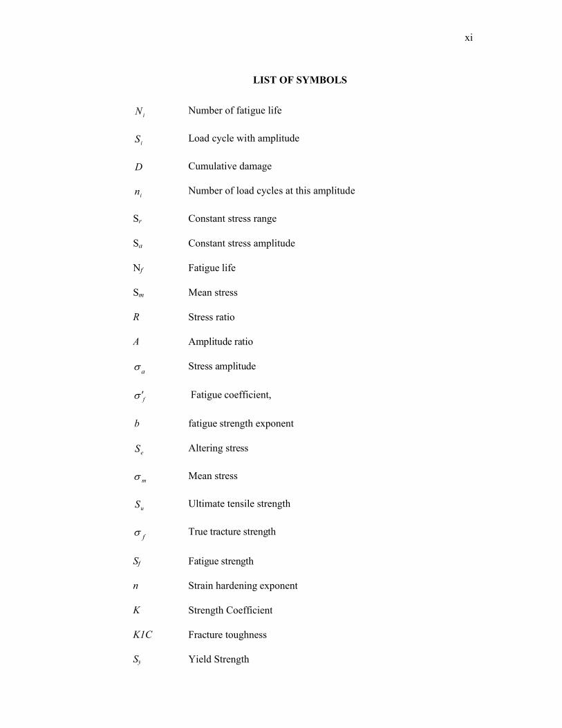
LIST OF SYMBOLS
iN Number of fatigue life
iS Load cycle with amplitude
D Cumulative damage
in Number of load cycles at this amplitude
Sr Constant stress range
Sa Constant stress amplitude
Nf Fatigue life
Sm Mean stress
R Stress ratio
A Amplitude ratio
a Stress amplitude
f Fatigue coefficient,
b fatigue strength exponent
eS Altering stress
m Mean stress
uS Ultimate tensile strength
f True tracture strength
Sf Fatigue strength
n Strain hardening exponent
K Strength Coefficient
K1C Fracture toughness
Sy Yield Strength

xii
LIST OF ABBREVIATIONS
AA Aluminum Alloy
A-A ASTM air to air typical fighter loading
Al Aluminium
ASTM American Society for Testing and Materials
CAD Computer-Aided Drafting
CAE Computer-Aided Engineering
DS Double Strap
FEM Finite Element Modeling
FE Finite Element
IC Internal Combustion
MBD Multibody Dynamics
SAE Society of Automotive Engineers
MPC Multi-Point Constraints
AISI Steel
CHAPTER 1
INTRODUCTION
1.1 INTRODUCTION
The most of the failure observed in the real structure and mechanical
component are due to the fatigue. In the design of the real system subjected to the
environment loadings, both the fatigue strength and dynamic properties of the
external loads are important. Fatigues are the progressive and localize material
damage that occurs when material is subjected to cyclic loading. Fatigue is an
important parameter to be considered in the behavior of components subjected to
constant and variable amplitude loading (Torres and Voorwald, 2002). In this study
variable amplitude are consider due to the service load histories. Realistic
representation of service load is a key ingredient of successes fatigue analysis.
Therefore, it is important to accurate measure the applied load on existing component
or structure or to predict loads on a component or structure does not yet exist.
(Koster and Field, 1973) suggested that the main mechanical property adversely
affected by machining is high cycle fatigue strength, the actual endurance limit being
dependent on the particular process used and the severity of operation. While it is
known that fatigue life is heavily influenced by residual stresses, the metallurgical
condition of the materials and the presence of notch-like surface irregularities
induced by machining play a key role (Novovic et al., 2004).
Cylinder block is the most critical component of engine in automotive
industry. The cylinder block or engine block is a machined casting (or sometimes an
assembly of modules) containing cylindrically bored holes for the pistons of a multi-
cylinder reciprocating internal combustion engine, or for a similarly constructed

2
device such as a pump. The engine cylinder block or "block" is cast in one piece.
Usually, this is the largest and most intricate single piece of metal in the automobile.
Even when the cylinders, cylinder heads, or cylinder sleeves are separate pieces, the
crankcase is still the largest single part in the engine. The cylinder block serves as the
main structural component of the engine and houses what’s commonly referred to as
the “the bottom end” (crankshaft, rods, pistons). Cylinder block structures are very
commonly subjected to fatigue loading (Rahman et al., 2006a).
Aluminum (Al) and its alloy have benefit over non metallic materials:
aluminum alloys have a high melting point, a good workability and also have a good
thermal conductivity. Aluminum alloys are one of the most capable material
selections for automobiles parts and electrical component to reduce their weight and
to increase their specific strength (Rahman et al., 2007a). Aluminum alloys is
suitable material due to safety, environmental and performance benefit.
Nitriding is now widely used in manufacturing for surface hardening of
ferrous and non-ferrous materials. Nitriding, one of the most widely used thermo-
chemical methods, produces a high compressive residual stresses on the surface of
components. Nitriding is a process for hardening the surface by diffusing nitrogen
into the surface. All machining, stress relieving, as well as hardening and tempering
are normally carried out before nitriding. Nitriding steels offer many advantages: a
much higher surface hardness is obtainable when compared with case-hardening
steels; they are extremely resistant to abrasion and have high fatigue strength.
1.2 PROBLEM STATEMENT
Cylinder block is the critical component in the internal combustion engine.
The cylinder block failure is due to the fatigue. Due to the market pressure for
improvements in productivity, reliability, ductility, wear resistance and profitability
of mechanical system, manufacturers replacing increasing demands on available
materials (Rahman et al., 2006). Surface treatment likes nitriding is used to improve
fatigue performance and increased the life. This simplification allows designers to
use linear elastic stress results obtained from multibody dynamic FE (finite element)

3
simulations for fatigue life analysis. To optimize component material, aluminum
alloys is the suitable material due to light and less weight. Nowadays, the most
capable material selection for automobiles parts and manufacturing is aluminum
alloys because it light and less weight.
1.3 OBJECTIVES OF THE PROJECT
This project is focus on the finite element based on the fatigue analysis of the
cylinder block for a two-stroke internal combustion engine using positive mean
loadings.
The overall objectives of this project were:
(i) To predict the fatigue life of the cylinder block using stress-life method and
to identify the critical locations
(ii) To investigate the effect of nitriding treatment
(iii)To optimize cylinder block’s material
1.4 SCOPE OF STUDY
This project concentrates on the stress-life approach under variable amplitude
loading. The scopes of study are as follows:
(i) Structural modeling
(ii) Finite element modeling (FEM)
(iii)Fatigue analysis
(iv)Surface treatment analysis
(v) Optimization of material
1.5 OVERVIEW OF THE REPORT
Chapter 1 gives the brief the content and background of the project. The
problem statement, scope of study and objectives are also discussed in this chapter.

4
Chapter 2 discusses about the fatigue life prediction method, fatigue life
prediction in variable amplitude loading and surface treatment process.
Chapter 3 presents the development of methodology, finite element modeling
and analysis, fatigue life prediction technique and linear elastic analysis.
Chapter 4 discusses the result and discussion of the project. The discussion
aims is to determine the predicted facts and correlate them with the current
international researches on the field of the fatigue mean stress effects.
Chapter 5 presents the conclusions of the project. Suggestions and
recommendations for the future work are put forward I this chapter.

5
CHAPTER 2
LITERATURE REVIEW
2.1 INTRODUCTION
The purpose of this chapter is to provide a review of the past research related
to the surface treatment, fatigue life method and variable amplitude loading. The
review is organized chronologically so as to offer approaching to how research hard
works have laid the base for subsequent studies, including the present research effort.
The review is fairly detailed so that the present research effort can be properly
modified to add to the present body of literature as well as to justify the scope and
direction of present research effort.
2.2 FATIGUE LIFE PREDICTION METHOD
Fatigue analysis can be used to determine how long the component can
maintain in a given service condition. In general, fatigue life refers to the ability of a
component to function in the presence of defect for a given loading. In practice, the
predominant failure mode is fatigue and hence, the term fatigue life analysis was
used to describe the analysis of the fatigue performance. In engineering design, the
criteria for the fatigue life of a component can very depending of the functional
requirements of material characteristic. The fatigue properties are determined from
the constant amplitude loading test. However, the real structural seldom experience
constant amplitude loading. Therefore, an irregular loading history must be reduced
to a series of constant amplitude events each with its corresponding mean and
amplitude for comparison with sample laboratory specimen testing data.

6
Rahman et al. (2007b) were studied about finite element based durability
assessment in a two- stroke free piston linear engine component using variable
amplitude loading. The study discussed the finite element analysis to predict the
fatigue life and identify the critical locations of the component. The effect of mean
stress on the fatigue life also investigated. The linear static finite element analysis
was performed using MSC. NASTRAN finite element software. The result was
capable of showing the contour plots of the fatigue life histogram and damage
histogram at the most critical location.
Conle and Mousseau (1991) used vehicle simulation and the finite element
result to generate the fatigue life contours for the chassis component using
automotive proving ground load history result combine with the computational
techniques. They concluded that the combination of the dynamics modeling, finite
element analysis is the practical techniques for the fatigue design of the automotive
component.
Srikantan et al. (2000) discussed vehicle durability and fatigue analysis using
data from proving ground testing. The authors discuss the differences between yield
strength based durability analysis and fatigue analysis. Fatigue analysis reduces the
design cycle and produces a more optimally design structure. The authors
concentrated on the design of the truck body structure and the service duty that
accompany them. The loads from proving ground test of similar vehicle. The
simulation used to calculate fatigue life is MSC.FATIGUE, while the stresses are
determined using MSC.NASTRAN. When the fatigue life design criteria are met a
prototype is then built and tested. If the design criteria are not met the prototype is
modified. The results from a correlation study showed the analytical strains from FE
analysis and proving ground test correlated very well.
Nadot and Denier (2003) have been studied fatigue phenomena for nodular
cast iron automotive suspension arms. They find out that the major parameter
influencing fatigue failure of casting components are casting defects. The high cycle
fatigue behavior is controllers mainly by surface defects and oxides while the low

7
cycle fatigue is governed by multiple cracks initiated independently from casting
defects.
Kim et al. (2002) also studied a method for simulating vehicles dynamic
loads, but they add durability assessment. For their multibody dynamics analysis
(MDA) they use DADS and a flexible body model. The model was for a transit bus.
For the dynamic stresses analysis MSC.NASTRAN was used. The fatigue life was
then calculated using a local strain approach. From the fatigue life, it was found that
the majority of the fatigue damaged occurred over a frequency range that depend on
terrain traveled (service or accelerated test course). This showed that the actual
service environment could be simulated instead of using an accelerated testing
environment.
2.3 VARIABLE AMPLITUDE LOADING
When components are subjected to variable amplitude service loads,
additional uncertainties arise, whether the loading in laboratory tests related to the
loads that could be expected to appear. Traditionally this problem is solved by using
the simplifying assumption of damage accumulation, and constant amplitude tests in
laboratory are transformed to variable amplitude severity by the Palmgren-Miner rule
which says that a
`
m
i i
i
N
nD
1 (2.1)
load cycle with amplitude iS adds to the cumulative damage D , a quantity ( iN1 ).
Here, iN denotes the fatigue life under constant amplitude iS loading with amplitude
and ni is the number of load cycles at this amplitude. The lack of validity of this
accumulation rule has been demonstrated in many applications and in consequence
its usage will introduce uncertainties which must be compensated for by safety
factors, see for instance (Berger et al., 2002).

8
One possible way to diminish the deviations from the damage accumulation
rule is to perform the laboratory experiments closer to the service behavior with
respect to the loads. A method for establishing a Wohler curve based on variable
amplitude loads has recently been developed and is presented
in a parallel paper (Johannesson et al., 2003).The use of this method should be
customized to each specific application by performing laboratory tests with load
spectra covering different service requirements. One idea is that service
measurements are used to establish a few reference load spectra for use in laboratory
tests. Based on the resulting variable amplitude Wohler curve, fatigue life can be
predicted for load spectra similar to the reference types.
Svensson et al. (2004) were conducted the fatigue life prediction based on
variable amplitude tests-specific applications. Three engineering components have
been tested with both constant amplitude loading and with different load spectra and
the results are analyzed by means of a new evaluation method. The method relies on
the Palmgren-Miner hypothesis, but offers the opportunity to approve the
hypothesis validity by narrowing the domain of its application in accordance with a
specific situation. In the first case automotive spot weld components are tested with
two different synthetic spectra and the result is extrapolated to new service spectra.
In the second case, the fatigue properties of a rock drill component are analyzed both
by constant amplitude tests and by spectrum tests and the two reference test sets are
compared. In the third case, butt welded mild steel is analyzed with respect to
different load level crossing properties and different irregularity factors.
Nolting et al. (2007) were investigated the effect of variable amplitude
loading on the fatigue life and failure mode of adhesively bonded double strap (DS)
joints made from clad and bare 2024-T3 aluminum. They concluded that the fatigue
life of a variable amplitude loading spectra can be calculated with reasonable
accuracy using an effective stress range vs. life fatigue curve. The effective stress
range vs. failure life curve is dependent on the bond geometry and therefore this
curve must be developed for component geometry of interest. The effective stress
range vs. life fatigue curve should be used to predict the fatigue life of clad

9
specimens if the failure mode of the clad specimens is expected to be adhesive
failure (i.e., if the spectrum includes large overload cycles).
Molent et al. (2007) have been evaluated the spectrum fatigue crack growth
using variable amplitude data. This paper summarizes a recent semi-empirical model
that appears to be capable of producing more accurate fatigue life predictions using
flight load spectra based on realistic in-service usage. The new model described here
provides an alternative means for the interpretation of full-scale and coupon fatigue
test data, and can also be used to make reliable life predictions for a range of
situations. This is a very important capability, particularly where only a single full-
scale fatigue test can be afforded and should lead to more economical utilization of
airframes.
2.4 SURFACE TREATMENT
The surface treatment of a component is a common site for initiation of fatigue
crack. Therefore, the manner in which in the surface is prepare during manufacturing
of the components has a vital role in dictating the initiation life for the surface fatigue
cracks. There exists a variety of surface treatment such as carburizing, nitriding, and
flame hardening which is design to impart high strength, wear resistance or corrosion
resistance locally in the near surface regions of the material.
Nitriding is often used high strength aluminum and titanium alloy to improve
fatigue performance (Novovic et al., 2004; Bell et al., 1998). Nitriding is now widely
used in manufacturing for surface hardening of ferrous and non-ferrous materials.
Nitriding ia a well-known case hardening process in which nitrogen is introduced
into the surface of a solid ferrous alloy by holding the alloy at a suitable temperature
in contact with a nitrogenous gas (usually ammonia) or a liquid cyanide bath (ASM,
1991). The nitriding temperature for all steels is generally between 530 and 5800C.
The principle reasons for nitriding are:
(i) To obtain high surface hardness
(ii) To increase wear resistance and anti-galling properties

10
(iii) To improve fatigue life
(iv) To obtain a surface that is resist to the softening effects of heat at
temperatures up to the nitriding temperature.
Although, at suitable temperature, all steels are capable of forming iron
nitrides in the presence of nascent nitrogen, the nitriding results are more favorable
in those steels containing one or more of the major nitride forming alloying elements.
Unalloyed carbon steels are not suitable for nitriding as they form an extremely
brittle case that spills readily and the hardness increase in the diffusion zone small.
Of the alloying elements commonly used in commercial steels, aluminum,
chromium, vanadium, and molybdenum are beneficial in nitriding as they form hard
nitrides that are stable up to the nitriding temperature. Since aluminum is the
strongest nitride former of the common alloying elements, aluminum-containing
steels (0.85-1.25% Al) yield the best nitriding results in terms of total alloy content.
Chromium-containing steels can approximate these results if their chromium content
is high enough.
Farrahi and Ghadbeig (1995) carried out an investigation into the effect of
various surface treatments on fatigue life of a tool steel. The effects of nitriding,
nitrocarburizing and shot peening on fatigue behavior of AISI D3 cold work tool
steel were investigated. They found out that nitriding and nitrocarburizing treatments
may improve abrasive-wear resistance of this material by increasing surface hardness
and the peening is the best treatment to improve the fatigue life of AISI D3 tool steel.
Karaoğlu (2002) conducted an investigation on the wear of plasma nitrided
AISI 5140 low-alloy steel in relation to the effect of parameters such as temperature,
time and nitrogen partial pressure. The work carried out by this author indicated that
the case depth and compound layer thickness that are formed during nitriding
increased with increasing process temperature and time and that, although the wear
resistance improved considerably after the plasma nitriding, for achieving the
maximum resistance to wear, process parameters should be chosen to minimize the
compound layer thickness and maximize the surface hardness and case depth.
11
Hosmani et al. (2005) investigated the nitriding behavior of a Fe–7Cr alloy at
580 °C in a gas mixture of ammonia and hydrogen, when the nitriding potential was
varied from 0.03 to 0.818 atm− 1/2. The nitrided zone in this material was observed to
be composed of two different regions, one with finely dispersed small CrN
continuous precipitates in α-Fe grains and another, near the surface, where the
precipitates were observed to coarsen in a discontinuous manner leading to a lamellar
CrN/α-Fe morphology. The maximum hardness in the nitrided zone and the nitriding
depth were both observed to increase with increasing nitriding potential, as long as
no iron nitride layer developed at the surface of the specimens. Also, the nitriding
depth was observed to depend roughly linearly on the square root of the nitriding
potential.
2.5 CONCLUSIONS
Different types of the fatigue life prediction method and durability
assessment approach have been reviewed in this chapter in conjunction with surface
treatment and variable amplitude. Many researchers have carried out their research
based on the fatigue life, durability assessment, surface treatment and variable
amplitude. Most of the methods available in literature reviews are used for the study.
The next chapter will be concentrated on the methodology will be presented in the

12
CHAPTER 3
METHODOLOGY
3.1 INTRODUCTION
The fatigue life of engineering structure principally depends upon that of its
critical structure members. There is an increasing within the internal combustion
engine industry in the ability to produce design that safe, reliable, light in weight,
economic and easy to produce. Nowadays, increasing demands in develop and
deliver the reliable products in a timely manner necessary more testing to be coupled
with the CAE procedures such as the finite element analysis and fatigue life analysis.
In this chapter, the proposed fatigue analysis, stress-life method, structural modeling,
material information and loading information are presented.

13
3.2 PROJECT FLOWCHART
Figure 3.1 shows the overall flowchart of the project
Stress/ Strain
Yes
No
Figure 3.1: Flowchart of the project
Computer Aided Design(SOLIDWORK)
FE Model(PATRAN)
FE Analysis(NASTRAN)
Fatigue Analysis
Lab Testing
Nitriding Analysis
Optimize
Cyclic Material Properties Component Load Histories
Optimize Fatigue Life
Boundary condition Loads
Fatigue lifeOk?

14
3.3 STRUCTURAL MODELING
The Figure 3.2 shows 3D structural modeling of cylinder block in two
different views. This structural modeling was developed using the computer aided
design (SOLIDWORK) software.
Figure 3.2: 3D structural modeling of the cylinder block (two different views)