Embed Size (px)
Citation preview

International Research Journal of Engineering and Technology (IRJET) e-ISSN: 2395 -0056
Volume: 02 Issue: 08 | Nov-2015 www.irjet.net p-ISSN: 2395-0072
© 2015, IRJET ISO 9001:2008 Certified Journal Page 1420
EFFECT OF NANOFLUID ON HEAT TRANSFER CHARACTERISTICS OF
SHELL AND TUBE HEAT EXCHANGERS: EFFECT OF ALUNIMIUM OXIDE
NANOFLUID
Sri. ELUMAGANDLA SURENDAR1, Mr. POREDDY PRASHANTH2, Smt. S NAGA SARADA3
1 H.O.D, Asst.Prof, Mechanical department, Warangal Inst of Tech & Scie,Telangana, India 2 Asst.Prof, Mechanical department, Warangal Inst of Tech & Scie,Telangana, India
3 Professor, Mechanical department,JNTUH,Telangana,India
---------------------------------------------------------------------***---------------------------------------------------------------------Abstract— Shell and tube heat exchangers represent
the most widely used vehicle for the transfer of heat in
industrial process applications. Shell and tube heat
exchangers have the ability to transfer large amounts
of heat in relatively low cost, serviceable designs. They
can provide large amounts of effective tube surface
while minimizing the requirements of floor space,
liquid volume and weight. A decade ago, with the rapid
development of modern nanotechnology, particles of
nanometre-size (normally less than 100 nm) are used
instead of micrometre-size for dispersing in base
liquids, and they are called nanofluids. In this thesis,
analytical investigations have been done on the shell
and tube heat exchanger, forced convective heat
transfer and flow characteristics of a nano fluid
consisting of mixing water and different volume
concentrations of Al2O3 nanofluid
(0.03,0.054,0.067and 0.135)% flowing under
turbulent flow conditions.
Introduction
Heat exchangers are devices in which heat is
transfer from one fluid to another. The most commonly
used type of heat exchanger is a shell-and-tube heat
exchanger. Shell-and-tube heat exchangers are used
extensively in engineering applications like power
generations, refrigeration and air-conditioning,
petrochemical industries etc. These heat exchangers can
be designed for almost any capacity. The main purpose in
the heat exchanger design is given task for heat transfer
measurement to govern the overall cost of the heat
exchanger.
The heat exchanger was introduced in the early
1900s to execute the needs in power plants for large heat
exchanger surfaces as condensers and feed water heaters
capable of operating under relatively high pressures. Both
of these original applications of shell-and-tube heat
exchangers continued to be used; but the design have
become highly sophisticated and specialized, subject to
various specific codes and practices. The broad industrial
use of shell-and-tube heat exchangers known today also
started in the 1900s to accommodate the demands of
emerging oil industry.
The steadily increasing use of shell-and-tube heat
exchangers and greater demands on accuracy of
performance prediction for a growing variety of process
conditions resulted in the explosion of research activities.
These included not only shell side flow but also, equally
important, calculations of true mean temperature
difference and strength calculations of construction
elements, in particular tube sheets.
The objective of the thesis is to formulate the
design algorithm and optimization procedure for a shell-
and-tube exchanger in which exchanger geometry is
determined from required performance for fixed pressure
drops. First step in the effective consideration of allowable
pressure drops is to establish a quantitative relationship
between velocity, friction factors, pressure drop of the
stream and number of transfer units. The solution of this
equation provides the core of such an algorithm.
SHELL AND TUBE HEAT EXCHANGER
By far the most common type of heat exchangers
to be encountered in the thermal applications is shell-and-
tube heat exchangers. These are available in a variety of
configurations with numerous construction features and
with differing materials for specific applications. This
chapter explains the basics of exchanger thermal design,
International Research Journal of Engineering and Technology (IRJET) e-ISSN: 2395 -0056
Volume: 02 Issue: 08 | Nov-2015 www.irjet.net p-ISSN: 2395-0072
© 2015, IRJET ISO 9001:2008 Certified Journal Page 1421
covering such topics as: shell-and-tube heat exchanger
components; classification of shell-and-tube heat
exchangers according to constructions.
Constructional Details of Shell and Tube Heat Exchanger
It is essential for the designer to have a good
knowledge of the mechanical features of shell-and-tube
heat exchangers and how they influence thermal design.
The principal components of shell-and-tube heat
exchangers are: Shell, shell cover, tubes, channel, channel
cover, tube sheet, nozzles, baffles, Other components
include tie-rods and spacers, pass partition plates,
impingement Plate, longitudinal baffles, sealing strips,
supports, and foundation. The Tubular Exchanger
Manufacturer is Association, TEMA, has introduced a
standardized nomenclature for shell-and-tube heat
exchangers. A three-letter code has been used to designate
the overall configurations. The three important elements
of any shell-and-tube heat exchangers are front head, the
shell and rear head design respectively. The Standards of
Tubular Exchanger Manufacturers Association (TEMA)
[15] describes the various components of various class of
shell-and-tube heat exchanger in detail.
Fixed Tube Sheet Shell and Tube Heat Exchanger
Use of multiple tubes because of that is increasing
the heat transfer area. Reason of increasing heat transfer
area is increase the velocity of fluid and lower effective ∆T.
There is different type of shell available, all shell are
identified regarding the diameter .Basically sizes of the
shell are 8, 10, 12 inches. We find 2 inches of increment
every step start from 13 inches to 25.From 25 to 39 we
find 2 inches increment and after 39 to 72 we find 3 inches
increment in shell. Tube size, which type of materials and
array are primary criteria of designing of tube and shell
type of mat exchanger. After done this step hydraulic
design will be done on automatically. Small tube gives less
cost with good thermal conductivity and Use of multiple
tubes because of that is increasing the heat transfer area.
Reason of increasing heat transfer area is increase the
velocity of fluid and lower effective ∆T. It will create less
shell area and size. Normally two arrays are available,
triangular array produces the more tube with lower cost
for particular heat transfer unit. We can control the
pressure difference in square type of array so it is more
preferable rather than the triangular type of array. When
the cleaning require because of mechanical work, on that
time square type of array are preferable. Wide pitch is
used in this type of array and 60o and 90o arrays have a
tendency to create a channeled flow. So that way fluid
have a tendency to pass between two row of tube so there
si not need to complete the full round of flow. This is
happen in each tube so it is big gain for evaporators and
condensers for vapor distributions.
Design Methods of Shell and Tube Heat Exchangers
First step in designing of heat exchanger, there is
two way to design heat exchanger.
1. LMTD
2. NTU Method.
General equation of heat exchanger is
LMT TFUAQ 0
Where ∆T is the Temperature difference between hot and
cold fluid
In terms of energy flow for heat exchanger, we can use this
equation for hot fluid,
hp TCMQ .
Where ∆T is the Temperature difference between hot
fluids

International Research Journal of Engineering and Technology (IRJET) e-ISSN: 2395 -0056
Volume: 02 Issue: 08 | Nov-2015 www.irjet.net p-ISSN: 2395-0072
© 2015, IRJET ISO 9001:2008 Certified Journal Page 1422
In terms of energy flow for heat exchanger, we can use this
equation for cold fluid,
cp TCMQ .
Where ∆T is the Temperature difference between hot
fluids
Log Mean Temperature Difference Method
Heat flows between the hot and cold streams due
to the temperature difference across the tube acting as a
driving force. The difference will vary with axial location.
Average temperature or effective temperature difference
for either parallel or counter flow may be written as:
2
1
21
lnT
T
TTLMTDTLM
Normal practice is to calculate the LMTD for counter flow
and to apply a correction factor FT, such that
CFLMTLM TFT ,.
The correction factors, FT, can be found theoretically and
presented in analytical form. The equation given below
has been shown to be accurate for any arrangement
having 2, 4, 6… 2n tube passes per shell pass.
112
112ln
1
1ln
1
1
2
2
2
21
RRP
RRP
PR
P
R
R
F
Where the capacity ratio, R, is defined as:
12
21
tt
TTR
The parameter P may be given by the equation:
SHELL
SHELL
N
N
XR
XP
/1
/11
Provided that 1R in the case that 1R , the
effectiveness is given by:
1.0
0
ShellShell NPN
PP
11
120
tT
ttP
1
1.
0
0
P
RPX
Gulyani and Mohanty [18] give alternate
equations for the calculation of temperature correction
factors. They have derived linear equations for the same
and established that the factor is below 0.5 % error. They
are given in Table 3.1.
Linear Equations for FT [18]
Note: RPG 11 0
Effectiveness-NTU Method
In the thermal analysis of shell-and-tube heat
exchangers by the LMTD method, an equation (3.1) has
been used. This equation is simple and can be used when
all the terminal temperatures are known. The difficulty
arises if the temperatures of the fluids leaving the
exchanger are not known. In such cases, it is preferably to
utilize an altogether different method known as the
effectiveness-NTU method. Effectiveness of shell-and-tube
heat exchanger is defined as:
NShell FT
1
2
3
4
5
1.208 G + 0.8037
0.237 G + 0.961
0.1202 G + 0.9835
0.0661 G + 0.991
0.0429 G + 0.994

International Research Journal of Engineering and Technology (IRJET) e-ISSN: 2395 -0056
Volume: 02 Issue: 08 | Nov-2015 www.irjet.net p-ISSN: 2395-0072
© 2015, IRJET ISO 9001:2008 Certified Journal Page 1423
TiSi
TiToT
TiSi
SoSiS
TTC
TTC
TTC
TTC
minmin
The group minC
UA is called number of transfer units, NTU.
Effectiveness for shell-and-tube heat exchanger can also
be expressed as:
max
min
min
,C
C
C
UA
Where S
T
T
S
C
Cor
C
C
C
C
max
min (depending upon their
relative magnitudes).
Kays and London have given expressions for shell-
and-tube heat exchangers. Some of their relationships for
effectiveness are given below:
For one shell pass, 2, 4, 6 tube passes
2
min
2
min2
minmin1
11exp1
11exp1
112
CNTU
CNTU
CC
For two shell pass, any multiple of 4 tubes
1
min
2
1
min1
2
1
min12
1
11
1
1
C
CC
Calculation of Heat Transfer Coefficient and Pressure Drops
Flow across banks of tubes is, from both
constructional and physical considerations, one of the
most effective means of heat transfer. However, it is
recognized quite early that ideal tube bank correlations, if
applied to shell-and-tube heat exchangers, needed
substantial corrections. In 1951, Tinker presented what
has become a classical paper on flow through the tube
bundles of shell-and-tube heat exchanger. He pointed out
that a number of differing paths existed for flow and
argued that the assumption that all of the fluid passed
through the whole of the bundle was false. This was
clearly demonstrated by his observations of the
performance of exchangers handling highly viscous oils.
He then proceeded to propose a flow model based on
variety of flow paths cross flow, bundle bypass, tube-baffle
leakage and shell-baffle leakage.
Mechanical Clearances in Shell and Tube Heat Exchanger
[8]
Flow Paths on Shell Side, A Cross Flow; B Window; C
Shell-Baffle
Heat Transfer Efficient
The Bell’s Delaware method uses ideal tube bank
hj and f factors and then corrects directly the resulting
hi and ∆Pi for derivations caused by the various split
streams. The ideal tube bank factor j and f is given as:
2
4
3
Re33.1 Re14.01
1
a
a
ttp
h
a
DLaj
2
4
3
Re33.1 Re14.01
1
b
b
ttp
b
DLbf
For possible computer applications, a simple set of
constants is given in [20] for the curve fit of the above
form.
The ideal heat transfer coefficient on shell side is defined
as:

International Research Journal of Engineering and Technology (IRJET) e-ISSN: 2395 -0056
Volume: 02 Issue: 08 | Nov-2015 www.irjet.net p-ISSN: 2395-0072
© 2015, IRJET ISO 9001:2008 Certified Journal Page 1424
3/2
.
PrMjCh piS
The shell side actual heat transfer coefficient is given in
equation:
rslcbiSS jjjjjhh
cj is the correction factor for baffle cut given by:
2
501cos2sin
180
501cos
44.127.1
11 c
tbbS
Sc
tbbS
S
c
B
DLD
DB
DLD
D
j
bj is the correction factor for bundle bypass flow is given
by:
c
ppss
ttptbbSefftpbb
tbb
bB
LN
DLDLDLL
DLj
50
1001
5.025.1exp
,
(3.21)
lj is the correction factor for baffle leakage flow is given
as:
lmr
ssl errj2.2
144.01144.0
(3.22)
tbsb
sb
sSS
Sr
m
tbsb
sS
SSr
Where mS is the cross flow area at the bundle centerline,
is given by
ttp
efftp
tbbS
bbbcm DLL
DLDLLS
,
sbS is the shell-to-baffle leakage area, given by
501cos236000436.0 1 c
sbSsb
BLDS
tbS is the tube-to-baffle hole leakage area, is given by
wttttbttb FNDLDS
14
22
sj is the correction factor for variable baffle spacing is
presented as:
bc
bo
bc
bi
b
bc
bo
bc
bi
b
s
L
L
L
LN
L
L
L
LN
j
1
1
4.0
jr is the correction factor for adverse temperature
gradient, which is given as:
For 20Re S
18.0
51.1
c
rrrN
jj
For 100Re20 S
180
Re20
rr
S
rrr jjj
For 100Re S 1rj
Nc is the total number of tube rows crossed in the entire
heat exchanger:
1 btcwtccc NNNN
In addition, the shell side heat transfer coefficient is
given by the following Nusselt number correlation:

International Research Journal of Engineering and Technology (IRJET) e-ISSN: 2395 -0056
Volume: 02 Issue: 08 | Nov-2015 www.irjet.net p-ISSN: 2395-0072
© 2015, IRJET ISO 9001:2008 Certified Journal Page 1425
14.0
3/155.0PrRe36.0
w
SS
S
eS
k
Dh
Equation (3.34) is given Kern and Krauss [21, 22]. Various
correction factors for heat transfer coefficient for shell
side flow are calculated as per suggested in the Delaware
method. The correlations for tube side Nusselt number
are:
For 2100Re T
14.03/1
.Pr.Re86.1
w
ti
TT
T
tiT
L
D
k
Dh
For 2100< 10000Re T
14.03/2
3/13/21Pr125Re116.0
w
ti
TT
T
tiT
L
D
k
Dh
For TRe > 10000
14.0
3/18.0PrRe023.0
w
TT
T
eT
k
Dh
Pressure Drop
The shell side pressure drop [20] is calculated as a
summation of the pressure drops for the inlet and exit
sections eP , the internal cross flow sections cP , and
the window sections wP . For a shell-and-tube
exchanger, the combined pressure drop is given as:
ewcS PPPP
The zonal pressure drops are calculated from ideal
pressure drop correlations and correlation factors, which
take account of bundle bypassing and leakage effects. The
baffled cross flow pressure drop is given by:
lbcibc RRPNP 1
The end zone pressure drop is given by:
c
tcw
bcieN
NRPP 12
and, the window pressure drop by:
lwibw RPNP
The correction factors for shell side pressure drop are
given as:
8.0115.0133.1exp
sr
lmsl rrR
(3.41)
n
bi
bc
n
bo
bc
sL
L
L
LR
22
3
50
10017.3exp
c
ppss
m
b
bB
LN
S
SR
According to Kern and Krauss [22], the shell side pressure
drop is given by the following expression:
14.0
212
wSe
bSSSS
D
NSNDGfP
The shell side friction factor correlation is of the form: 19.0
Re4475.0
SSf
The tube side pressure drop is given by:
International Research Journal of Engineering and Technology (IRJET) e-ISSN: 2395 -0056
Volume: 02 Issue: 08 | Nov-2015 www.irjet.net p-ISSN: 2395-0072
© 2015, IRJET ISO 9001:2008 Certified Journal Page 1426
T
tpT
wTti
tpTT
T
NSNG
D
NSNLGfP
2
14.0
225.12
The first term is due to friction and the second term
is due to return losses. Most of the pressure drop is due to
surface friction inside the exchanger in an attempt to
increase the heat transfer. Therefore, only the straight
tube pressure is considered. For smooth pipes, the
correlations for friction factor are of the
form:mt
TTT Kf
Re
Note that TK 16, mt = -1 for 2100Re T , whereas
TK 0.046, mt -0.2 for 2100Re T
The overall heat transfer coefficient (U) is related to
individual heat transfer coefficient as:
f
ti
t
T
t
ti
t
TS
RD
D
k
D
D
D
hhU
ln
2
111
It is essential that the designer of shell-and-tube
heat exchangers becomes familiar with the principles of
the various correlations and methods in numerous
publications, their advantages and disadvantages,
limitations and degrees of sophistication versus probable
accuracy and other related aspects. All the published
methods can be logically divided into several groups:
1. The early developments based on flow over ideal tube banks or even single tubes.
2. The “integral” approach, which recognizes baffled cross flow modified by the presence of window, but treats the problem on an overall basis without considerations of the modified effects of leakage and bypass.
3. The “analytical” approach based on Tinker’s multistream model and his simplified method.
4. The “stream analysis method”, which utilizes a rigorous reiterative approach based on Tinker’s model.
5. The Delaware method, which uses the principles of the Tinker’s model but interprets them on an overall basis, that is, without reiterations.
6. Numerical prediction methods.
Nanofluids clearly exhibit enhanced thermal conductivity,
which goes up with increasing volumetric fraction of
nanoparticles. The current review does concentrate on
this relatively new class of fluids and not on colloids which
are nanofluids because the latter have been used for a long
time. Review of experimental studies clearly showed a lack
of consistency in the reported results of different research
groups regarding thermal properties. The effects of
several important factors such as particle size and shapes,
clustering of particles, temperature of the fluid, and
dissociation of surfactant on the effective thermal
conductivity of nanofluids have not been studied
adequately. It is important to do more research so as to
ascertain the effects of these factors on the thermal
conductivity of wide range of nanofluids. Classical models
cannot be used to explain adequately the observed
enhanced thermal conductivity of nanofluids. Recently
most developed models only include one or two
postulated mechanisms of nanofluids heat transfer. For
instance, there has not been much fundamental work
reported on the determination of the effective thermal
diffusivity of nanofluids nor heat transfer coefficients for
nanofluids in natural convection. There is a growth is the
use of colloids which are nanofluids in the biomedical
industry for sensing and imaging purposes. This is directly
related to the ability to design novel materials at the
nanoscale level alongside recent innovations in analytical
and imaging technologies for measuring and manipulating
nanomaterials. This has led to the fast development of
commercial applications which use a wide variety of
manufactured nanoparticles. The production, use and
disposal of manufactured nanoparticles will lead to
discharges to air, soils and water systems. Negative effects
are likely and quantification and minimization of these
effects on environmental health is necessary. True
knowledge of concentration and physicochemical
properties of manufactured nanoparticles under realistic
conditions is important to predicting their fate, behavior
and toxicity in the natural aquatic environment. The

International Research Journal of Engineering and Technology (IRJET) e-ISSN: 2395 -0056
Volume: 02 Issue: 08 | Nov-2015 www.irjet.net p-ISSN: 2395-0072
© 2015, IRJET ISO 9001:2008 Certified Journal Page 1427
aquatic colloid and atmospheric ultrafine particle
literature both offer evidence as to the likely behavior and
impacts of manufactured nanoparticles, and there is no
pretense that a review duplicating similar literature about
the use of colloids which are also nanofluids is attempted
in the current review. Owing to their enhanced properties
as thermal transfer fluids for instance, nanofluids can be
used in a plethora of engineering applications ranging
from use in the automotive industry to the medical arena
to use in power plant cooling systems as well as
computers.
THERMAL ANALYSIS OF SHELL AND TUBE HEAT
EXCHANGER
ALUMINUM
CASE 1 - VOLUME FRACTION OF 0.03
Open work bench 14.5>select steady state thermal in
analysis systems>select geometry>right click on the
geometry>import geometry>select IGES file>open
Imported model
Section view
Aluminum material properties
Thermal conductivity of aluminum = 35w/mk
Specific heat =896 j/kg k
Density = 0.0000027kg/mm3
Model >right click>edit>select generate mesh
Boundary conditions
T 1 =303 k
T 2 =353 k
Select steady state thermal >right click>insert>select
convection
Select steady state thermal >right click>insert>select heat
flux
Select steady state thermal >right click>solve
Solution>right click on solution>insert>select
temperature

International Research Journal of Engineering and Technology (IRJET) e-ISSN: 2395 -0056
Volume: 02 Issue: 08 | Nov-2015 www.irjet.net p-ISSN: 2395-0072
© 2015, IRJET ISO 9001:2008 Certified Journal Page 1428
Temperature
Heat flux
CASE 2 - VOLUME FRACTION OF 0.054
Temperature
Heat flux
CASE 3 - VOLUME FRACTION OF 0.067
Temperature
Heat flux

International Research Journal of Engineering and Technology (IRJET) e-ISSN: 2395 -0056
Volume: 02 Issue: 08 | Nov-2015 www.irjet.net p-ISSN: 2395-0072
© 2015, IRJET ISO 9001:2008 Certified Journal Page 1429
CASE 4 - VOLUME FRACTION OF 0.135
Temperature
Heat flux
COPPER
Material properties
Thermal conductivity of copper = 385w/mk
Specific heat =385 J/kgk
CASE 1 - VOLUME FRACTION OF 0.03
Temperature
Heat flux
CASE 2 - VOLUME FRACTION OF 0.054
Temperature
Heat flux
CASE 3 - VOLUME FRACTION OF 0.067
Temperature
International Research Journal of Engineering and Technology (IRJET) e-ISSN: 2395 -0056
Volume: 02 Issue: 08 | Nov-2015 www.irjet.net p-ISSN: 2395-0072
© 2015, IRJET ISO 9001:2008 Certified Journal Page 1430
Heat flux
case 4 - volume fraction of 0.135
Temperature
Heat flux
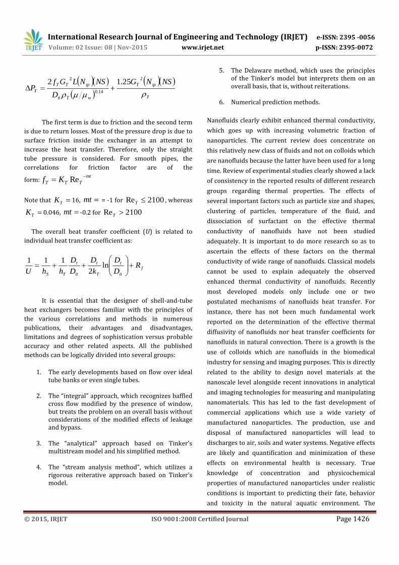
CFD ANALYSIS
CASE 1 - VOLUME FRACTION OF 0.03
Fluid properties
Density =1083 kg/mm3
Specific heat = 4182.95 J/Kgk
Thermal conductivity =0.6285(w/mk)
Viscosity = 0.0961 Kg/ms
GEOMETRY
Fluid geometry

International Research Journal of Engineering and Technology (IRJET) e-ISSN: 2395 -0056
Volume: 02 Issue: 08 | Nov-2015 www.irjet.net p-ISSN: 2395-0072
© 2015, IRJET ISO 9001:2008 Certified Journal Page 1431
Meshed model
Select faces → right click → create named section → enter
name → cold fluid inlet
Select faces → right click → create named section → enter
name → cold fluid outlet
Select faces → right click → create named section → enter
name → hot water inlet
Select faces → right click → create named section → enter
name →hot water outlet
Update project>setup>edit>model>select>energy
equation (on)>ok
Materials> Materials > new >create or edit >specify fluid
material or specify properties > ok
Select fluid
Boundary conditions
Inlet temperatures(T) 303k,353 K
Inlet pressure(P) 101325 Pa
Inlet velocity(V) 1.4412 m/s
Solution > Solution Initialization > Hybrid Initialization
>done
Run calculations > no of iterations = 100> calculate >
calculation complete>ok
Results>edit>select contours>ok>select location (inlet,
outlet, wall.etc)>select pressure>apply
Iterations

International Research Journal of Engineering and Technology (IRJET) e-ISSN: 2395 -0056
Volume: 02 Issue: 08 | Nov-2015 www.irjet.net p-ISSN: 2395-0072
© 2015, IRJET ISO 9001:2008 Certified Journal Page 1432
Pressure
Temperature
Mass flow rate
"Flux Report" Mass Flow Rate (kg/s) -------------------------------- -------------------- cold_water_inlet 103.57964 cold_water_outlet -108.75418 hot_water_inlet 51.458931 hot_water_outlet -46.267403 interior-_trm_srf -501.7912 interior-part-_trm_srf 0 wall-_trm_srf 0 wall-part-_trm_srf 0 ---------------- -------------------- Net 0.016983032
Heat transfer rate
"Flux Report" Total Heat Transfer Rate (w) -------------------------------- -------------------- cold_water_inlet 2098665 cold_water_outlet -8188493.5 hot_water_inlet 11803789 hot_water_outlet -5711336 wall-_trm_srf 0 wall-part-_trm_srf 0 ---------------- -------------------- Net 2624.5
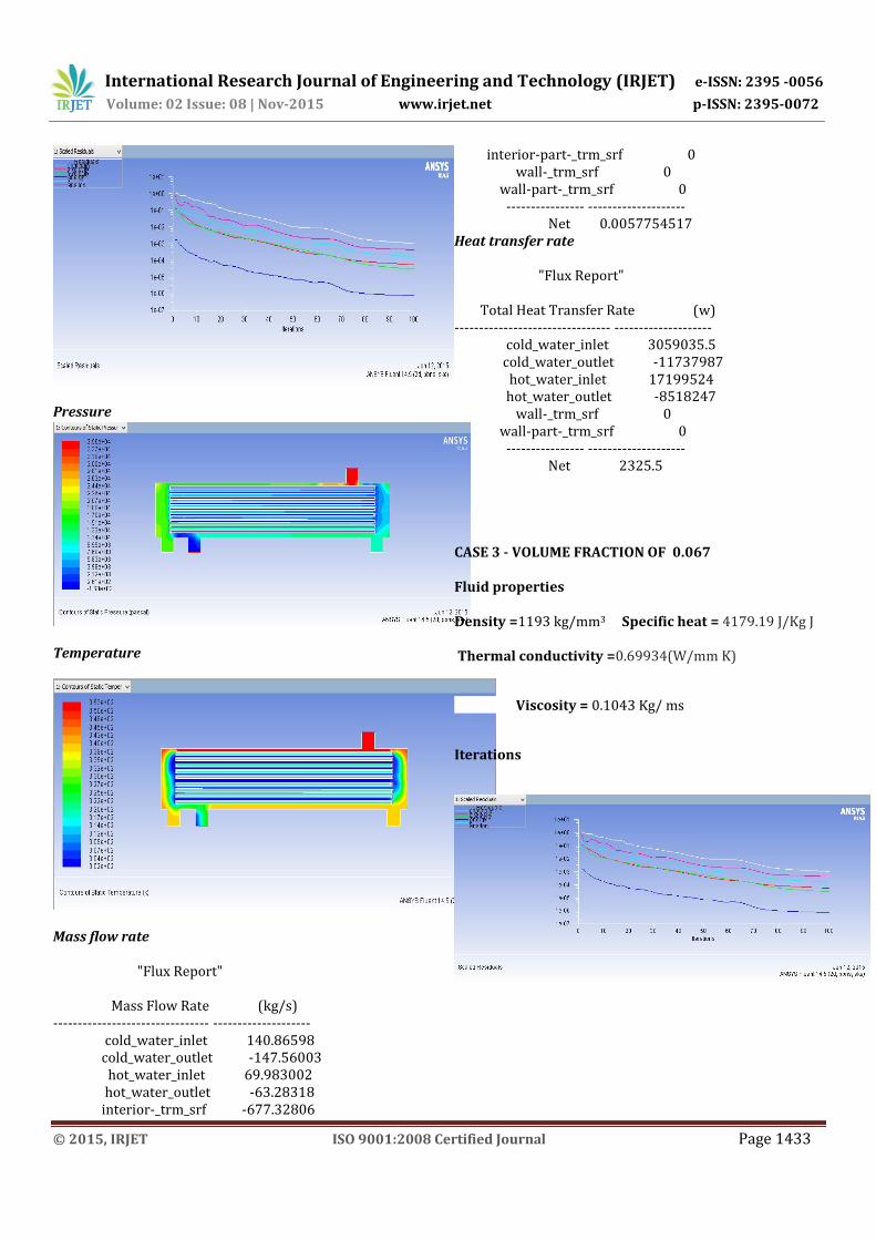
CASE 2 - VOLUME FRACTION OF 0.054
Fluid properties
Density =1156.06 kg/mm3 Specific heat = 4180.519 J/Kg
K
Thermal conductivity =0.67511(W/mm K)
Viscosity = 0.1014 Kg/ms
Iterations
International Research Journal of Engineering and Technology (IRJET) e-ISSN: 2395 -0056
Volume: 02 Issue: 08 | Nov-2015 www.irjet.net p-ISSN: 2395-0072
© 2015, IRJET ISO 9001:2008 Certified Journal Page 1433
Pressure
Temperature
Mass flow rate
"Flux Report" Mass Flow Rate (kg/s) -------------------------------- -------------------- cold_water_inlet 140.86598 cold_water_outlet -147.56003 hot_water_inlet 69.983002 hot_water_outlet -63.28318 interior-_trm_srf -677.32806
interior-part-_trm_srf 0 wall-_trm_srf 0 wall-part-_trm_srf 0 ---------------- -------------------- Net 0.0057754517 Heat transfer rate
"Flux Report" Total Heat Transfer Rate (w) -------------------------------- -------------------- cold_water_inlet 3059035.5 cold_water_outlet -11737987 hot_water_inlet 17199524 hot_water_outlet -8518247 wall-_trm_srf 0 wall-part-_trm_srf 0 ---------------- -------------------- Net 2325.5
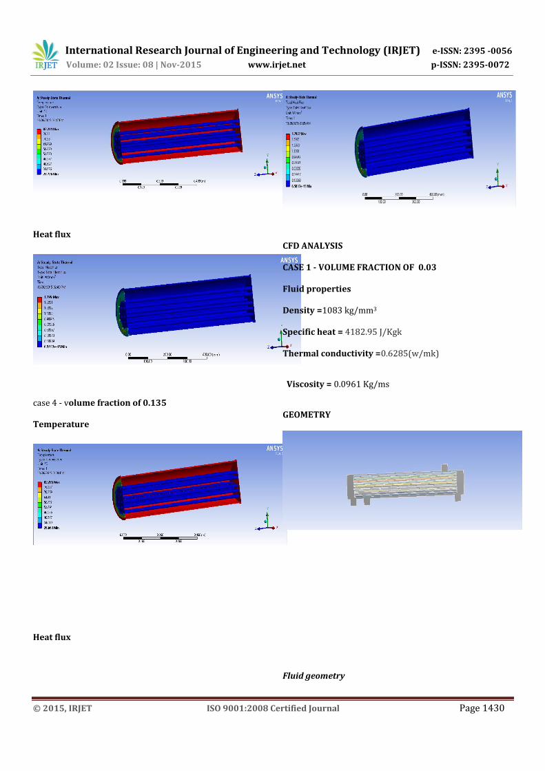
CASE 3 - VOLUME FRACTION OF 0.067
Fluid properties
Density =1193 kg/mm3 Specific heat = 4179.19 J/Kg J
Thermal conductivity =0.69934(W/mm K)
Viscosity = 0.1043 Kg/ ms
Iterations
International Research Journal of Engineering and Technology (IRJET) e-ISSN: 2395 -0056
Volume: 02 Issue: 08 | Nov-2015 www.irjet.net p-ISSN: 2395-0072
© 2015, IRJET ISO 9001:2008 Certified Journal Page 1434
Pressure
Temperature
Mass flow rate
"Flux Report" Mass Flow Rate (kg/s) -------------------------------- -------------------- cold_water_inlet 150.92784 cold_water_outlet -158.0211 hot_water_inlet 74.981781 hot_water_outlet -67.882912 interior-_trm_srf -733.61743 interior-part-_trm_srf 0 wall-_trm_srf 0 wall-part-_trm_srf 0 ---------------- -------------------- Net 0.005607605
Heat transfer rate
Total Heat Transfer Rate (w) -------------------------------- -------------------- cold_water_inlet 2854924 cold_water_outlet -10983589 hot_water_inlet 16052890
hot_water_outlet -7921921 wall-_trm_srf 0 wall-part-_trm_srf 0 ---------------- -------------------- Net 2304
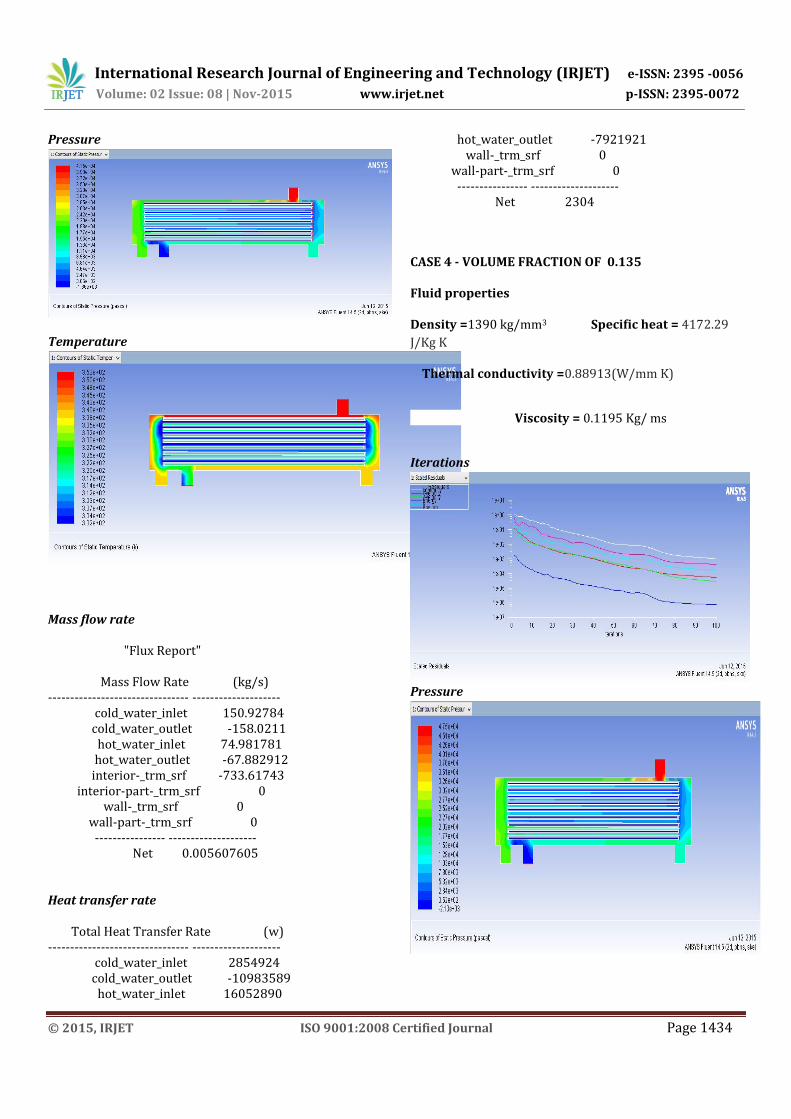
CASE 4 - VOLUME FRACTION OF 0.135
Fluid properties
Density =1390 kg/mm3 Specific heat = 4172.29
J/Kg K
Thermal conductivity =0.88913(W/mm K)
Viscosity = 0.1195 Kg/ ms
Iterations
Pressure

International Research Journal of Engineering and Technology (IRJET) e-ISSN: 2395 -0056
Volume: 02 Issue: 08 | Nov-2015 www.irjet.net p-ISSN: 2395-0072
© 2015, IRJET ISO 9001:2008 Certified Journal Page 1435
Temperature
Mass flow rate
"Flux Report" Mass Flow Rate (kg/s) -------------------------------- -------------------- cold_water_inlet 130.22917 cold_water_outlet -136.50139 hot_water_inlet 64.69857 hot_water_outlet -58.42131 interior-_trm_srf -618.79193 interior-part-_trm_srf 0 wall-_trm_srf 0 wall-part-_trm_srf 0 ---------------- -------------------- Net 0.0050430298
Heat transfer rate
"Flux Report" Total Heat Transfer Rate (w) -------------------------------- -------------------- cold_water_inlet 2639156.8 cold_water_outlet -10185357 hot_water_inlet 14840733 hot_water_outlet -7292392.5 wall-_trm_srf 0 wall-part-_trm_srf 0 ---------------- -------------------- Net 2140.25 THERMAL RESULTS TABLE
ALUMINUM
COPPER
Volume
fraction
Temperature
(0C)
Heat
flux(W/mm2)
0.03 82.266 1.8056
0.054 82.276 1.8011
0.067 82.281 1.799
0.135 82.285 1.797
GRAPHS
Temperature
Volume
fraction
Temperature
(0C)
Heat
flux(W/mm2)
0.03 82.026 0.69241
0.054 82.064 0.6887
0.067 82.068 0.68702
0.135 82.094 0.6866

International Research Journal of Engineering and Technology (IRJET) e-ISSN: 2395 -0056
Volume: 02 Issue: 08 | Nov-2015 www.irjet.net p-ISSN: 2395-0072
© 2015, IRJET ISO 9001:2008 Certified Journal Page 1436
Heat flux
By observing the results, the variation of temperature
distribution and heat flux is very less using nanofluids with
different volume fractions.
CFD RESULT TABLE
Volu
me
fract
ion
Pressur
e(pa)
Velocity
(m/s)
Temper
ature
(k)
Mass
flow
rate(kg
/sec)
Heat
tran
sfer
rate
(W)
0.03 2.26e+0
4 3.88 353 0.01698
2624.
5
0.05
4
3.56e+0
4 4.86 353
0.00575
1 2325
0.06
7
4.15e+0
4 5.26 353
0.00560
7 2304
0.13
5
4.75e+0
4 5.63 353
0.00504
3 2140
GRAPHS

International Research Journal of Engineering and Technology (IRJET) e-ISSN: 2395 -0056
Volume: 02 Issue: 08 | Nov-2015 www.irjet.net p-ISSN: 2395-0072
© 2015, IRJET ISO 9001:2008 Certified Journal Page 1437
By observing the CFD analysis results, the pressure drop is
increasing by increasing the volume fraction, mass flow
rate and heat transfer rate are decreasing by increasing
the volume fraction.
CONCLUSION
In this thesis, analytical investigations have been done on
the shell and tube heat exchanger, forced convective heat
transfer and flow characteristics of a nanofluid consisting
of water and different volume concentrations of Al2O3
nanofluid (0.03,0.054,0.067and 0.135)% flowing under
turbulent flow conditions. The properties of the nanofluid
with different volume fractions are calculated using
theoretical calculations. Thermal and CFD analysis is done
in Ansys. By observing the thermal analysis results, the
variation of temperature distribution and heat flux is very
less using nanofluids with different volume fractions. By
observing the CFD analysis results, the pressure drop is
increasing by increasing the volume fraction, mass flow
rate and heat transfer rate are decreasing by increasing
the volume fraction.
REFERENCES
1. Shell-and-Tube Heat Exchanger R. Shankar
Subramanian, Mcadams, W.H., Heat Transmission,
(McGraw-Hill, New York), pp 430-441, 1954
2. Jenssen, S.K., Heat exchanger optimization,
Chemical Eng. Progress, 65(7), pp 59, 1969
3. Sidney, K., and Jones, P.R., Programs for the price
optimum design of heat exchangers, British
Chemical Engineering, April,pp 195-198, 1970
4. Steinmeyer, D.E., Energy price impacts design,
Hydrocarbon Process, November, pp 205, 1976.
5. Steinmeyer, D.E., Take your pick – capital or
energy, CHEMTECH, March, 1982
6. Peter, M.S. and Timmerhaus, K.D., Plant design
and economics for chemical engineers, pp 678-
696 3rd Ed., McGraw-Hill, New York, 1981
7. Kovarik, M., Optimal heat exchanger, Journal of
Heat Transfer, Vol. 111, May, pp 287-293, 1989
8. Polley, G.T., Panjeh Shahi, M.H. and Nunez, M.P.,
Rapid design algorithms for shell-and-tube and
compact heat exchangers, Trans IChemE, Vol.
69(A), November,pp 435-444, 1991
9. Jegede, F.O. and Polley, G.T., Optimum heat
exchanger design, Trans IChemE, Vol. 70(A),
March, pp 133-141, 1992
10. Saffar-Avval, M. and Damangir, E., A general
correlation for determining optimum baffle
spacing for all types of shell-and-tube heat
exchangers, International Journal of Heat and Mass
Transfer, Vol. 38 (13), pp 2501-2506, 1995
11. Poddar, T.K. and Polley, G.T., Heat exchanger
design through parameter plotting, Trans IChemE,
Vol. 74(A), November, pp 849-852, 1996
12. Steinmeyer, D.E., Understanding ∆P and ∆T in
turbulent flow heat exchangers, Chemical
Engineering Progress, June,pp 49-55, 1996
13. Soylemez, M.S., On the optimum heat exchanger
sizing for heat recovery, Energy Conversion and
Management, 41, pp1419-1427, 2000
14. Murlikrishna, K. and Shenoy, U.V., Heat exchanger
design targets for minimum area and cost, Trans
IChemE, Vol. 78(A), March, pp 161-167, 2000

International Research Journal of Engineering and Technology (IRJET) e-ISSN: 2395 -0056
Volume: 02 Issue: 08 | Nov-2015 www.irjet.net p-ISSN: 2395-0072
© 2015, IRJET ISO 9001:2008 Certified Journal Page 1438
15. Bevevino, J.W., ET. al., Standards of tubular
exchanger manufacturing association, TEMA, New
York, 6th Edition, 1988
16. Mukherjee, R., Effectively design shell-and-tube
heat exchangers, Chemical Engineering Progress,
February, pp 21-37, 1998
17. Crane, R.A., Thermal Aspects of Heat Exchanger
Design, University of South Florida, Department
of Mechanical Engineering
18. Gulyani, B.B. and Mohanty, B., Estimating log
mean temperature difference, Chemical
Engineering, November, pp127-130, 2001
19. Sukhatme, S.P., Heat exchangers, A Text Book on
Heat Transfer, University Press India Limited, pp
201-226 1996
BIOGRAPHIES
I ELUMAGANDLA SURENDAR, working as Assistant Professor and H O D in mechanical engineering department in Warangal Institute of Technology and Science,warangal, Telangana. I have been completed Master of Science in mechanical engineering from University Of Norway in April 2008, and completed Master Of Technology in Thermal Engineering in 2014. I got nearly 10+ years of teaching experience and carried different kind of projects during this period.also attended many National level conferences and technical workshops organised in different colleges or universities.