Embed Size (px)
Citation preview

Effect of MRAI Timers on
BGP Convergence Times
by
Rajvir Gill
B.Tech., Lovely Professional University, 2010
Thesis Submitted in Partial Fulfillment
of the Requirements for the Degree of
Master of Applied Science
in the
School of Engineering Science
Faculty of Applied Sciences
Rajvir Gill 2013
SIMON FRASER UNIVERSITY
Spring 2013
All rights reserved. However, in accordance with the Copyright Act of Canada, this work may
be reproduced, without authorization, under the conditions for “Fair Dealing.” Therefore, limited reproduction of this work for the
purposes of private study, research, criticism, review and news reporting is likely to be in accordance with the law, particularly if cited appropriately.

ii
Approval
Name: Rajvir Gill
Degree: Master of Applied Science
Title of Thesis: Effect of MRAI Timers on BGP Convergence Times
Examining Committee:
Chair: John D. Jones, Associate Professor
Ljiljana Trajkovic Senior Supervisor Professor
William A. Gruver Supervisor Emeritus Professor
R. H. Stephen Hardy Internal Examiner Emeritus Professor School of Engineering Science
Date Defended/Approved: January 22, 2013

iii
Partial Copyright Licence

iv
Abstract
The Border Gateway Protocol (BGP) is an Inter-Autonomous System (AS) routing
protocol currently used in the Internet. The Minimal Route Advertisement Interval (MRAI)
plays a prominent role in convergence of the BGP. The previous studies have suggested
using the adaptive MRAI and reusable timers to reduce the BGP convergence time. The
adaptive MRAI timers perform well under the normal load of BGP update messages.
However, a large number of BGP update messages may flood the Internet routers.
In this thesis, we propose a new algorithm called MRAI with Flexible Load Dispersing
(FLD-MRAI) that reduces the router's overhead by dispersing the load in case of a large
number of BGP update messages. We examine the MRAI timers under both the normal
and heavy loads of BGP update messages. The proposed algorithm is evaluated using
the ns-BGP network simulator. Network topologies are derived from the BCNET BGP
traffic and generated using various topology generators.
Keywords: Communication networks; routing protocols; BGP; MRAI.

v
Dedication
To God Almighty for being my eternal pillar
and my parents for all their
unconditional love and support

vi
Acknowledgements
I would like to express gratitude to my senior supervisor r . il ana Tra i r her
exceptional guidance, encouragement, and advice for my research work. Her ability to
approach research problems, high scientific standards, and hard work set an example
for me and anyone who she guides.
My sincere thanks to my committee members Prof. R. H. Stephen Hardy, Prof. William
A. Gruver, and Assoc. Prof. John D. Jones for providing valuable comments and
suggestions. I would like to thank Prof. Kohshi Okumura for reviewing my thesis and
providing valuable feedback.
I am also thankful to my colleagues in the Communication Networks Laboratory. Special
thanks to Sukhchandan Lally, Tanjila Farah, and Ravinder Paul for their wonderful
friendship and support during my graduate studies. I would also like to thank Mr. Toby
Wong from BCNET for providing BGP traffic traces.
My deepest gratitude goes to my family for their unconditional love and support
throughout my life. I am thankful to my father Jasmel Singh Gill for his care and love.
Many thanks to my mother Barjinder Gill for her everlasting love and support. Mother,
you are my encouragement pillar and thank you for cooking delicious dishes. Big thanks
to my sisters and brother in laws for their constant advice and support. Lastly, thanks go
to my nephews and niece Anshveer, Bevin, and Anayat for being my stress relievers and
for being quiet during my study time.
vii
Table of Contents
Approval .......................................................................................................................... ii Partial Copyright Licence ............................................................................................... iii Abstract .......................................................................................................................... iv Dedication ....................................................................................................................... v Acknowledgements ........................................................................................................ vi Table of Contents .......................................................................................................... vii List of Tables ................................................................................................................... x List of Figures................................................................................................................. xi List of Acronyms ............................................................................................................ xiii
1. Introduction .......................................................................................................... 1 1.1. Contribution ............................................................................................................ 2
1.1.1. Implementation of the FLD-MRAI algorithm in ns-2.34 ................................ 2 1.1.2. Validation of the FLD-MRAI algorithm ......................................................... 3 1.1.3. Comparison and analysis of the FLD-MRAI algorithm with other
BGP options ................................................................................................ 3 1.2. Thesis Outline ........................................................................................................ 3 1.3. Related Work .......................................................................................................... 4
2. Border Gateway Protocol (BGP) .......................................................................... 7 2.1. BGP Operation ..................................................................................................... 10 2.2. BGP Storage of routes ......................................................................................... 11 2.3. BGP Packet Format .............................................................................................. 12 2.4. BGP Update Message Format .............................................................................. 13 2.5. Autonomous System (AS) .................................................................................... 14
3. Dynamic Behavior of BGP ................................................................................. 19 3.1. Initiating BGP Routes ........................................................................................... 19 3.2. BGP Decision Process ......................................................................................... 20
3.2.1. Phase 1: BGP Calculation of DoP ............................................................. 22 3.2.2. Phase 2: BGP Route Selection ................................................................. 22 3.2.3. Phase 3: BGP Route Dissemination .......................................................... 23 3.2.4. An example of the Cisco Router ................................................................ 24
3.3. BGP Convergence Time ....................................................................................... 24 3.4. MRAI Timers ........................................................................................................ 26
3.4.1. Per-Destination MRAI Timer ..................................................................... 27 3.4.2. Per-Peer MRAI Timer ................................................................................ 29
3.5. BGP Processing Delay ......................................................................................... 30

viii
4. FLD-MRAI Algorithm .......................................................................................... 33 4.1. CPU Utilization and Processing Delay .................................................................. 33 4.2. Modified Reusable Timers .................................................................................... 36 4.3. Duration of MRAI .................................................................................................. 39
4.3.1. Tshort /Tup update after another Tshort /Tup update ................................ 42 4.3.2. Tshort /Tup update after a Tlong/Tdown update ........................................ 42 4.3.3. Tlong/Tdown update after a Tshort /Tup update ........................................ 43 4.3.4. Tlong/Tdown update after another Tlong/Tdown update ........................... 43
4.4. Space and Time Complexity of the FLD-MRAI Algorithm ..................................... 44
5. Implementation of the FLD-MRAI Algorithm ..................................................... 47 5.1. Ns-2 Implementation ............................................................................................ 47 5.2. Implementation Features ...................................................................................... 50 5.3. Simulation Scenarios ............................................................................................ 50 5.4. Simulation Topologies .......................................................................................... 50
5.4.1. Network Topology 1 .................................................................................. 51 5.4.2. Network Topology 2 and Topology 3 ......................................................... 52 5.4.3. Network Topology 4 and Topology 5 ......................................................... 53
5.5. Assumptions ......................................................................................................... 54
6. Performance Evaluation ..................................................................................... 55 6.1. Validation tests ..................................................................................................... 55
6.1.1. Network Topology with five Nodes ............................................................ 55 6.1.1.1. Theoretical Explanation .............................................................. 55 6.1.1.2. Experimental evaluation ............................................................. 57
6.1.2. Completely Connected Network Topology with fifteen Nodes ................... 58 6.2. Network Topology 1 .............................................................................................. 61
6.2.1. FLD-MRAI with the Normal Load Scenario ................................................ 61 6.2.2. FLD-MRAI with the High Load Scenario .................................................... 65 6.2.3. Summary of Network Topology 1 .............................................................. 66
6.3. Network Topology 2 .............................................................................................. 67 6.3.1. FLD-MRAI with the Normal Load Scenario ................................................ 67 6.3.2. FLD-MRAI with the High Load Scenario .................................................... 68
6.4. Network Topology 3 .............................................................................................. 69 6.4.1. FLD-MRAI with the Normal Load Scenario ................................................ 69 6.4.2. FLD-MRAI with the High Load Scenario .................................................... 70
6.5. Network Topology 4 .............................................................................................. 71 6.5.1. FLD-MRAI with the Normal Load Scenario ................................................ 71 6.5.2. FLD-MRAI with the High Load Scenario .................................................... 72
6.6. Network Topology 5 .............................................................................................. 73 6.6.1. FLD-MRAI with the Normal Load Scenario ................................................ 73 6.6.2. FLD-MRAI with the High Load Scenario .................................................... 76 6.6.3. Summary of Network Topology 5 .............................................................. 77

ix
7. Future Work ........................................................................................................ 79
8. Conclusions ........................................................................................................ 80
References ................................................................................................................... 81
Appendices .................................................................................................................. 85 Appendix A. Test script of a network with five nodes used for validation tests ............. 86 Appendix B. Test script of a network with fifteen nodes used for validation tests ......... 89

x
List of Tables
Table 1. List of Events during BGP Convergence. ..................................................... 37
Table 2. Network Topologies used in Simulations. ..................................................... 51
Table 3. Example of BCNET BGP routing table updates. .......................................... 52
Table 4. Values of parameters for 100-node and 200-node topologies. ..................... 53
Table 5. GLP specific parameters. ............................................................................. 54
Table 6. Average Convergence Time for 5 Nodes Topology for Different BGP Options. ................................................................................ 58
Table 7. Average Convergence Time for 67 Nodes Topology for Different BGP Options. ................................................................................ 66
Table 8. Overall Number of Update Messages 67 Nodes Topology for Different BGP Options. ................................................................................ 66
Table 9. Average Convergence Time for 100 Nodes Topology for Different BGP Options. ................................................................................ 67
Table 10. Overall Number of Update Messages 100 Nodes Topology for Different BGP Options. ................................................................................ 67
Table 12. Overall Number of Update Messages 200 Nodes Topology for Different BGP Options. ................................................................................ 69
Table 13. Average Convergence Time for 300 Nodes Topology for Different BGP Options. ................................................................................ 71
Table 14. Overall Number of Update Messages 300 Nodes Topology for Different BGP Options. ................................................................................ 71
Table 15. Average Convergence Time for 500 Nodes Topology for Different BGP Options. ................................................................................ 78
Table 16. Overall Number of Update Messages 500 Nodes Topology for Different BGP Options. ................................................................................ 78

xi
List of Figures
Figure 1. Two types of the Internet routing protocol: Intra-domain and Inter-domain. ...................................................................... 7
Figure 2. Connectivity of the intra-domain and inter-domain routing in a network. ...................................................................................................... 8
Figure 3. Tree-like structure of the Internet having a root (NSFNET backbone) and branches. ....................................................... 9
Figure 4. Connectivity of the ASes via BGP within the network. .................................. 10
Figure 5. Four types of BGP messages. ..................................................................... 10
Figure 6. Three types of the RIB and their explanation. .............................................. 12
Figure 7. BGP packet header format. .......................................................................... 12
Figure 8. BGP update message format. ...................................................................... 13
Figure 10. Flowchart of allocation of the ASes by the IANA. ......................................... 16
Figure 11. Allocation of the AS numbers to RIRs by the IANA. ..................................... 17
Figure 12. A network with the transit, stub, and multihomed ASes. ............................... 18
Figure 13. Flowchart of the BGP decision process. ....................................................... 21
Figure 14. Example of a network with four ASes to illustrate the use of timers. ............. 28
Figure 15. Illustration of a per-destination timer. ........................................................... 29
Figure 16. Illustration of a per-peer timer. ..................................................................... 30
Figure 17. A model of the uniform BGP processing delay. ............................................ 31
Figure 18. Two load scenarios of the FLD-MRAI algorithm. .......................................... 35
Figure 19. Example of the network with five routers to illustrate the difference between FLD-MRAI and default MRAI..................... 36
Figure 20. Explanation of the different advertisement events. ....................................... 37
Figure 21. All advertisements sent between 66 s and 67 s are associated with the same reusable timer. .................................................... 39
Figure 22. Fifteen reusable timers with MRAI rounds equal to 15 s or 30 s. .................. 41
Figure 23. Timer1 is reused after 15 s for the next Tshort /Tup update. ........................ 42
Figure 24. Timer1 is reused after 30 s for the next Tshort /Tup update. ........................ 43
Figure 25. Timer1 is reused after 15 s for the next Tlong/Tdown update. ...................... 43

xii
Figure 26. Timer1 is reused after 30 s for the next Tlong/Tdown update. ...................... 44
Figure 27. Pseudocode of the proposed FLD-MRAI algorithm. ..................................... 45
Figure 28. The structure of ns-2 with two languages C++ and OTcl [37]. ...................... 47
Figure 29. Implementation of the FLD-MRAI algorithm in the ns-BGP node with shaded modified BGP modules. ..................................... 48
Figure 30. Example of the possible paths in the network of five routers. ....................... 55
Figure 31. Example of the high load scenario in the shortest path of the network with five routers. .............................................. 56
Figure 32. Ns-nam graph of a network with five nodes. ................................................. 57
Figure 33. Completely connected network with fifteen nodes. ....................................... 58
Figure 34. BGP convergence time vs. node number. .................................................... 59
Figure 35. Optimal value of MRAI for an empirical BGP processing delay. ................... 60
Figure 36. Convergence time for network Topology 1 for the Tshort event. .................. 62
Figure 37. Convergence time for network Topology 1 for the Tlong event..................... 62
Figure 38. Convergence time for network Topology 1 for the Tup event. ...................... 63
Figure 39. Convergence time for network Topology 1 for the Tdown event. .................. 64
Figure 40. The overall number of update messages for network Topology 1 for all events. ............................................................... 64
Figure 41. Convergence time for network Topology 1 for the high load scenario. ......... 65
Figure 42. The overall number of update messages for network Topology 1 for the high load scenario. ............................................ 66
Figure 43. Convergence time for network Topology 5 for the Tshort event. .................. 73
Figure 44. Convergence time for network Topology 5 for the Tlong event..................... 74
Figure 45. Convergence time for network Topology 5 for the Tup event. ...................... 75
Figure 46. Convergence time for network Topology 5 for the Tdown event. .................. 75
Figure 49. The overall number of update messages for network Topology 5 for the high load scenario. ............................................ 77

xiii
List of Acronyms
Adj-RIB-In Adjacent Routing Information Base Incoming
Adj-RIB-Out Adjacent Routing Information Base Outgoing
AfriNIC African Network Information Centre
APNIC Asia-Pacific Network Information Centre
ARIN American Registry for Internet Numbers
AS Autonomous System
ASN Autonomous System Number
BGP Border Gateway Protocol
BRITE Boston university Topology Representative Internet Topology gEnerator
CANARIE Canada’s Ad anced Research and Inn ation Network
CIDR Classless Inter-Domain Routing
CPU Central Processing Unit
DANTE Delivery of Advanced Network Technology to Europe
DNS Domain Name System
DoP Degree of Preference
eBGP exterior Border Gateway Protocol
EGP Exterior Gateway Protocol
FIB Forwarding Information Base
FIFO First In First Out
FLD-MRAI MRAI with Flexible Load Dispersing
GLP Generalized Linear Preference
GT-ITM Georgia Tech Internetwork Topology Models
IANA Internet Assigned Numbers Authority
iBGP interior Border Gateway Protocol
ICANN Internet Corporation for Assigned Names and Numbers
IGP Interior Gateway Protocol
IGRP Interior Gateway Routing Protocol
IP Internet Protocol
IPv4 Internet Protocol version 4
IPv6 Internet Protocol version 6
IS-IS Intermediate System To Intermediate System

xiv
ISP Internet Service Provider
LACNIC Latin America and Caribbean Network Information Centre
LAN Local Area Network
Loc-RIB Local Routing Information Base
MED Multi-Exit Discriminator
MRAI Minimal Route Advertisement Interval
NSFNET National Science Foundation Network
NLRI Network Layer Reachability Information
NS Network Simulator
ORAN Optical Regional Advanced Network
OSPF Open Shortest Path First
OTcl Object-oriented Tool Command Language
PED Path Exploration Damping
RCN Root Cause Node
RIB Routing Information Base
RIP Routing Information Protocol
RIPE Réseaux IP Européens Network Coordination Centre
RIR Regional Internet Registry
SSFNET Scalable Simulation Framework Network
SSLD Sender Side Loop Detection
TCL Tool Command Language
TCP Transmission Control Protocol

1
1. Introduction
Among the routing protocols, the Border Gateway Protocol (BGP) is one of the
viable solutions that operate in a network of the Internet's size. BGP provides
mechanisms for supporting Classless Inter-Domain Routing (CIDR). It is a method for
assigning the I addresses and the current Internet uses the “h p-by-h p” paradigm r
r uting. BG supp rts any p licy c n rming t the “h p-by-h p” paradigm, hence, BG
is a vital inter-AS routing protocol for the current Internet [1].
The Minimal Route Advertisement Interval (MRAI) is the interval limitation that
defines the minimum duration of time between two subsequent advertisements of the
same destination. The MRAI affects BGP convergence. Its default value is 30 s, which is
efficient for a variety of network topologies and under many network conditions [1]. The
continuous MRAI timers control the MRAI value and may be of the per-destination or
per-peer types. In case of the per-destination timers, each network destination is
associated with one per-destination MRAI timer that independently limits advertisements
to various destinations. However, the per-destination MRAI timers are not used because
of the Internet size. In case of the per-peer timers, each peer in the network is
associated with one per-peer MRAI timer. The timer starts ticking when the source router
sends a route advertisement to its peers. The per-peer MRAI timers adversely affect
advertisements to each destination. For example, if an advertisement establishes a
connection relying on the per-peer MRAI timer of another Autonomous System (AS), all
subsequent advertisements sent to that AS will be delayed, since the subsequent
advertisements have to wait for the previous timer to expire. The optimal MRAI values
depend on the network size, topology, traffic volume, and network conditions [2].
The processing delay of an update message performed by a BGP router
significantly affects the BGP convergence time. This is the total time of an update
waiting in the queue and the time required for a BGP router to process it. Most proposed
solutions use the uniform processing delay for evaluating the BGP convergence time

2
[3]–[5]. They assume that a BGP router processes update messages sequentially one-
by-one. When an update message is being processed, the update message that follows
has to wait in the queue. Hence, the delay in processing updates affects the processing
time of all update messages that follow. Measurements show that the majority of the
update messages are processed within 200 ms. The processing time for update
messages varies from 2.4 ms to 200 ms and the average processing time for most of
update messages is 101 ms with the upper bound of 400 ms [6].
1.1. Contribution
This thesis aims to improve the BGP convergence time and reduce the overall
number of update messages received within the convergence period. We introduce a
new algorithm called MRAI with Flexible Load Dispersing (FLD-MRAI) [7] that limits the
MRAI based on advertisement events that occur in the network. FLD-MRAI performs
well in networks where the traffic load is unspecified. FLD-MRAI reduces the router's
overhead of processing a large number of BGP update messages. A summary of the
contributions follows:
1.1.1. Implementation of the FLD-MRAI algorithm in ns-2.34
We implemented the FLD-MRAI algorithm in an existing BGP model (ns-BGP)
that has been based on the ns-2 network simulator [5]. The ns-BGP model was
developed from the BGP-4 model of the Scalable Simulation Framework Network
(SSFNET) simulator [3]. We propose modifications to reusable timers and changes to
the MRAI durations based on BGP advertisement events. When we develop the FLD-
MRAI algorithm we do not consider routing policies and assume that each AS contains
only one BGP router [3]. BGP always prefers the local shortest path as the degree of
preference (DoP) and, hence, we propose modifications to DoP calculations. We
propose the FLD-MRAI algorithm for peer-to-peer networking in heterogeneous and
large networks. The modified ns-BGP that contains an implementation of the FLD-MRAI
algorithm has been made available to research community [7].

3
1.1.2. Validation of the FLD-MRAI algorithm
We perform tests to validate the FLD-MRAI algorithm and evaluate performance
of the FLD-MRAI algorithm using various network topologies. We validate the
implementation of the FLD-MRAI algorithm in ns-BGP by using a simple network of five
routers. We choose a completely connected topology with fifteen nodes to validate the
performance of the algorithm. We also compare simulation results in terms of the
convergence time and the overall number of update messages with the results of the
previously reported studies.
1.1.3. Comparison and analysis of the FLD-MRAI algorithm with other BGP options
We use genuine BGP data and two topology generators to generate realistic
network topologies. We compare and analyze the performance of the FLD-MRAI
algorithm with other BGP options. We also evaluate the performance of the FLD-MRAI
algorithm using different MRAI values.
1.2. Thesis Outline
The organization of the thesis is as follows: Chapter 2 starts with an overview of
BGP, BGP routing, an explanation of AS, and a description of the BGP update message
format. In Chapter 3, we discuss the dynamic behavior of BGP, which includes the
description of the MRAI timers, BGP convergence time, BGP processing delay, BGP
decision process, and DoP of BGP. In Chapter 4, we describe the FLD-MRAI algorithm.
The implementation of the FLD-MRAI algorithm in ns-2.34 and simulation scenarios are
described in Chapter 5. The performance evaluation based on various network
topologies is shown in Chapter 6 while the future work is addressed in Chapter 7. We
conclude the thesis with Chapter 8. The Tool Command Language (TCL) topologies for
validation tests are given in the Appendices.

4
1.3. Related Work
A single reusable MRAI timer for all route advertisements sent during a short
time interval has been proposed in the past [2], [3]. The MRAI defines the granularity of
an MRAI round and the total number of reusable MRAI timers. The update messages
may be divided into the higher-priority and the lower-priority classes [10]. The update
messages in the higher priority class advertise the routes faster than in the lower priority
class. A global timer is used to reduce the overhead. The receiver classifies the update
messages based on the per-destination forwarding-path tree. The update messages that
are received through existing tree trunks are called on-tree update messages. According
to the priority class, on-tree update messages are pr cessed aster r m the recei er’s
perspective. Consequently, the sender has to infer the priority class of update messages
(higher or lower) and may experience additional overhead.
Networks with routers that have different types of MRAI timers may experience
significantly higher convergence time and exponentially increased number of BGP
update messages compared to the routers having the same MRAI timers [11]. The
adaptive MRAI timers based on the announced paths have been recommended [12].
These improved MRAI timers decrease the BGP convergence time and their BGP
convergence time is a linear function of the traffic load in a network. To ensure that the
connection is alive, keepalive messages are sent at regular intervals. The hold timer is
the maximum number of seconds that elapse between the receptions of successive
keepalive messages from the sender. Experiments have shown that setting the
keepalive timer to 10 s and the hold timer to 15 s reduces the BGP convergence time
[12]. The path exploration damping (PED) algorithm proposes timer of 35 s, which may
reduce the number of update messages and convergence time and may be a viable
alternative to default MRAI timers [13]. Several artifacts in BGP message handling
procedures that may cause superfluous invocations of the MRAI timer during the route
selection process have been identified [14]. The additional update messages that arise
during route establishment process do not adversely affect the processing of the MRAI
timer and result in faster BGP convergence. The delay due to convergence limits of BGP
may also be examined based on the power laws of the Internet topology and the BGP
protocol standards [15], [16]. These reports also show that processing efficiency of the

5
r uter’s central processing unit (CPU) and the value of MRAI timers significantly affect
the BGP convergence time.
A BGP model that considers convergence properties, number of update
messages, and effects of routing policy scenarios has been reported [17], [18]. It was
illustrated using the SSFNET simulations that the sender side loop detection (SSLD) and
the optimal values for MRAI reduce the BGP convergence time [3]. For each specific
network topology, there is an optimal MRAI value that reduces the BGP convergence
time [19]. The Internet routing instability is the rapid fluctuation of the network
reachability information due to the path or link failures. The routing instability is affected
by a large number of updates exchanged in the network. Any change in the network
leads to route change that increases size of the routing tables. Furthermore, the routing
instability increases the BGP convergence time, number of update messages, and
packet loss. Moreover, higher levels of instability may often cause loss of the internal
connectivity of large and complex networks [19]. An earlier study developed a model that
provides theoretical upper and lower bounds of the convergence time in case of both the
path and BGP router failures [20]. Measurements demonstrate that latency due to the
router or link failure might reach tens of minutes. Multihoming is the configuration of
multiple Internet Protocol (IP) addresses on a single host. Multihomed networks have
multiple links to the same/different Internet Service Providers (ISPs) and to the local
networks. For multihoming, the customers announce their IP address space to their
ISPs. The traffic between customers and the ISPs is routed via BGP. The ISPs then
disseminate the routing information to the Internet. Measurements also demonstrate that
the delay due to link failure in multihomed networks may last as long as fifteen minutes
after a network fault. SSLD detects loops in the path and, after their removal, only paths
without loops are announced. Simulation results also show that the modified MRAI that
performs SSLD causes network convergence within 30 s. During the router or path
failure, the convergence time is n times the MRAI value, where n is the longer path
announced to a destination [20].
The ghost-flushing algorithm [21] recommends a minor change to BGP that
reduces the convergence time at the time of node failure in the Internet. In this case,
BGP is allowed to withdraw messages immediately without any MRAI delay and the
MRAI delay of 30 s is imposed on the announcement messages [1]. The consistency

6
assertion algorithm checks the route consistency by analyzing the information received
from the neighboring speakers and from earlier update messages [22]. This algorithm
achieves the shorter convergence time by discarding the infeasible routes. However, this
algorithm requires additional calculations to check the consistency from the neighboring
speakers. A previous study Root Cause Node (RCN) proposes modifications in the
update messages, which contain extra information including a sequence number and the
address of the RCN [23]. This scheme reduces both the BGP convergence time and
number of route changes. However, it alters the BGP update packet format and routing
tables in order to store some additional information.
When the shortest path to the destination becomes available, the network
converges more quickly than when a path or a BGP router fails [20], [24]. This is
because in the Internet Protocol version 4 (IPv4), BGP has a wide network diameter that
consists of thousands of ASes. The MRAI delay of 30 s increases the transmission time
of every advertisement in the exterior Border Gateway Protocol (eBGP).
The load-balancing algorithm is employed in the homogenous client-server
architecture where data relocation takes place when local node has no available CPU to
execute processes [25]. The effect of BGP processes on the active routers is analyzed
in the Sprint IP network [8]. It is sh wn that BG pr cesses utilize 60% a r uter’s C U
time during active CPU cycles. BGP processes consume the maximum CPU utilization
during short intervals (5 s). The large number of messages during a CPU cycle may
increase CPU load, which may delay BGP convergence and affect router stability. A
r uter’s C U l ad depends n the number BG messages received during a specific
MRAI round. A router receives a large number of update messages due to the Internet
size. The large number of update messages increases the size of BGP routing table,
which may require large memory and CPU utilization [9]. A high CPU utilization of a BGP
router also causes additional queuing delays within the BGP convergence period [26].
Hence, memory and CPU utilization are the essential requirements for a BGP router to
successfully send information to all other BGP peers in the network.
7
2. Border Gateway Protocol (BGP)
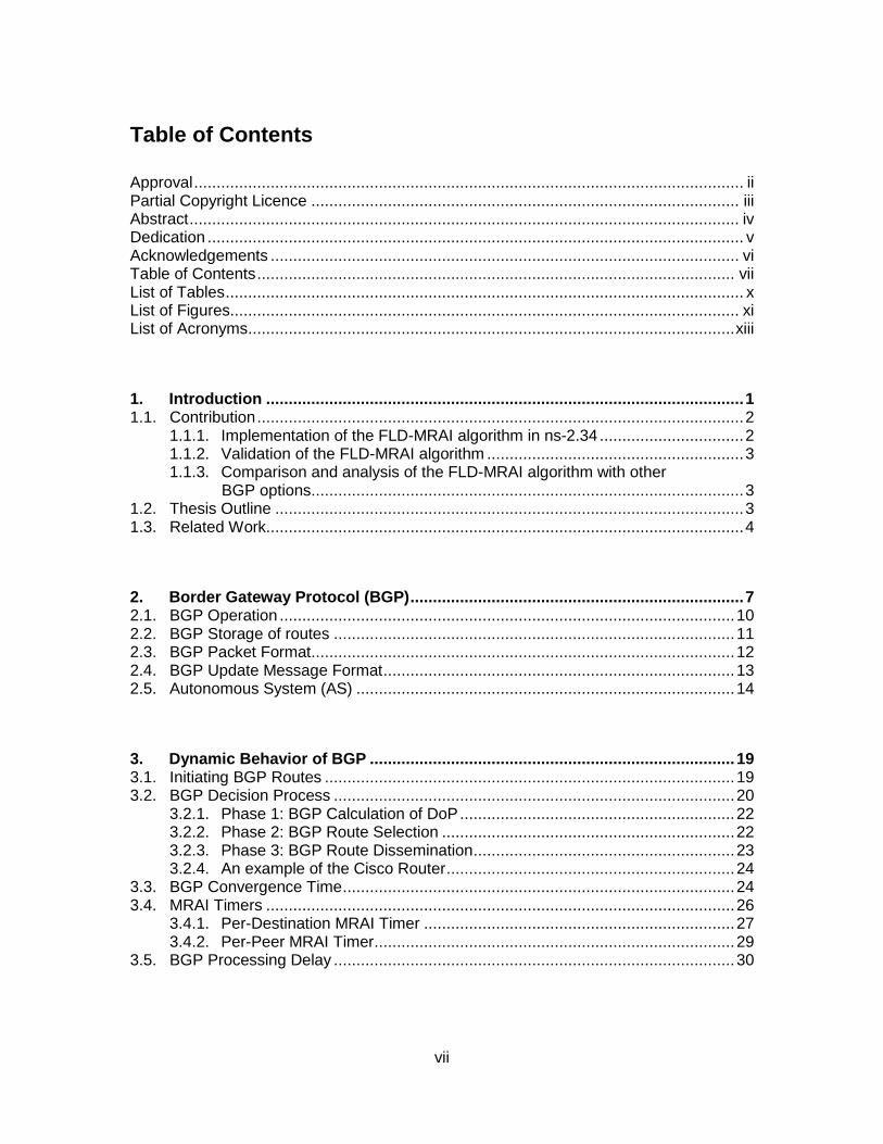
A routing protocol describes the distribution of routing information and
communication between the routers in a network. Before sending routing information to
the entire network, a routing protocol sends the routing information first to its neighbors.
A routing protocol selects the routes between any two routers with the help of routing
algorithms. Figure 1 shows the two types of the Internet routing protocols: Intra-domain
and Inter-domain.
Figure 1. Two types of the Internet routing protocol: Intra-domain and Inter-domain.
Intra-domain routing establishes routes among the routers within a single AS.
Interior Gateway Protocol (IGP) is an intra-domain routing routing protocol. Inter-domain
routing establishes the routes among the ASes. The Internet is composed of a set of

8
networks known as ASes, which are controlled by a single network administrator.
Exterior Gateway Protocol (EGP) is an inter-domain routing protocol.
Intra-domain and inter-domain routing protocols function together in the Internet.
The routing domain of IGP is a single AS while the routing domain for EGP is the entire
Internet. Examples of IGP are:
• Open Shortest Path First (OSPF)
• Intermediate System to Intermediate System (IS-IS)
• Routing Information Protocol (RIP)
• Interior Gateway Routing Protocol (IGRP).
OSPF and IS-IS are the link state routing protocols while RIP and IGRP are the distance
vector routing protocols. BGP is an inter-domain routing protocol.
The difference between the intra-domain and inter-domain routing is shown in
Figure 2. A link between BGP routers belonging to different ASes is known as the
external link while the link among BGP routers within the same AS is known as the
internal link.
Figure 2. Connectivity of the intra-domain and inter-domain routing in a network.

9
BGP is based on EGP [27], which assumes that the Internet has a tree structure having
a root called the backbone that controls the Internet and the branches, as shown in
Figure 3. EGP was widely used in the National Science Foundation Network (NSFNET)
[28] to exchange network reachability information among the local networks and the
NSFNET backbone. EGP was replaced by BGP to in order to fully decentralize the
Internet.
Figure 3. Tree-like structure of the Internet having a root (NSFNET backbone) and branches.
BGP assumes that the Internet is interconnected by a number of ASes. The
connectivity of ASes within the network is illustrated in Figure 4. BGP enables the
Internet to develop into a fully decentralized system. A BGP router exchanges the
network reachability information with other routers in the network. The network
reachability information consists of the list of reachable ASes. Based on this information,
the path loops may be detected. BGP also supports CIDR and follows the "hop-by-hop"
routing model, which sends information to its neighbors first before sending it to the
entire network.

10
Figure 4. Connectivity of the ASes via BGP within the network.
2.1. BGP Operation
BGP operates over a reliable transport protocol to avoid retransmission of data,
separation of packets, and sequencing. BGP also follows the error notification approach:
If there is no error, then all data are sent before closing the connection. BGP operates
over the Transmission Control Protocol (TCP) and employs port 179 to begin the
connection. BGP enables only one process per router at a time. The BGP routers
exchange four types of messages during the period of connection, as shown in Figure 5.
Figure 5. Four types of BGP messages.

11
To establish a TCP connection with a server’s BGP router, the client router sends
an open message to a server and verifies the connection. During the first data exchange
with a server’s router, the client router sends the entire BGP routing table. The update
messages are sent to the routers as soon as the routing table changes. These update
messages may announce advertisement of new routes or withdrawal of the old routes.
Hence, due to these updates a server’s BGP router always has the updated version of
the routing table of its client BGP router. To guarantee that the connection is still alive,
the BGP routers send the keepalive messages at regular intervals. A notification
message is sent to the BGP routers if the connection faces errors. After receiving a
notification message, the BGP routers close the connection.
2.2. BGP Storage of routes
A BGP route describes the path information that connects the source and
destination via the AS_path attributes. The routing information is conveyed by the BGP
update messages. The AS_path attribute classifies the ASes along the path used to
process the information. These attributes consist of AS numbers of source, destination,
and all ASes along the path. The update messages describe the information regarding a
BGP route in the path field. The IP address of the destination is described in the Network
Layer Reachability Information (NLRI) field. The routing information is stored in the
Routing Information Base (RIB). There are three RIB types: Adjacent Routing
Information Base Incoming (Adj-RIB-In), Local Routing Information Base (Loc-RIB), and
Adjacent Routing Information Base Outgoing (Adj-RIB-Out), as shown in Figure 6.
Before advertising a route to the neighboring routers, a BGP router may also add
or modify the AS_path attributes. Furthermore, a BGP router may also notify its
neighboring routers that the previously advertised routes have been withdrawn.

12
Figure 6. Three types of the RIB and their explanation.
2.3. BGP Packet Format
The BGP packet header in the update message format for any advertisement or
withdrawal message is of a fixed size and consists of four fields: marker, length, type,
and data, as shown in Figure 7.
Figure 7. BGP packet header format.
The marker field (16 bytes) includes a verification value for the receiver and
helps detect the loss in signalization. The second field in the packet format is length (2
bytes) that signifies the total length of the message. The type field (1 byte) indicates the
type and type code of the open, update, notification, or keepalive message. For
example, the type code for the open messages is 1. The data field (variable length) is an
optional field and includes upper-layer information [29].

13
2.4. BGP Update Message Format
The routing information is exchanged between the BGP routers with the help of
the update messages. The routing information within the update message includes the
information about the links between the ASes. This information may be used in creating
a graph to understand the path behavior. The type code of the BGP update message is
2. The fields in the BGP update message format are shown in Figure 8.
Figure 8. BGP update message format.
The unfeasible route length field specifies the total length of the withdrawn routes
field. If the value of the unfeasible route length field is zero, then the withdrawn routes
field does not exist in the update messages. The absence of information about the
withdrawn routes field in the update messages indicates that no routes have been
withdrawn. The withdrawn routes field includes the IP address prefixes of the withdrawn
routes, where each IP address prefix is determined as the combination of the length and
the prefix. The length field signifies the length of the IP address prefix in bits and the
prefix field contains the IP address prefixes.
The total path attributes length field specifies the total length of the path
attributes field. If the value of the total path attributes length is zero, then the NLRI does
not exist in the update messages. The path attributes field is present in every update

14
message whether it is advertisement of a new route or withdrawal of an old route. Path
attributes are determined as the sets of attribute type, attribute length, and attribute
value. The path attributes field is variable in length.
The BGP routers exchange the NLRI with the help of update messages.
Parameters that are used to calculate the length of the NLRI [1] are: length of update
message, total path attributes length, and unfeasible routes length. The length of the
update message is computed in the BGP header. The combined length of the BGP
header, the total path attribute length field, and the unfeasible routes length field is 23
octets. The minimum length of the update messages is 23 octets, which include 19
octets for BGP header, 2 octets for the unfeasible routes length field, and 2 octets for the
total path attribute length field. The last two parameters are calculated in the variable
part of the BGP update message format. The NLRI is determined as the combination of
the length and the prefix. The length field indicates the length of the IP address prefix in
bits. The prefix field represents the network addresses of the prefixes.
2.5. Autonomous System (AS)
An AS is composed of a set of Internet routers that are controlled by a single
network administrator. The exchange of reachability information and path data between
two ASes is performed by the inter-domain routing protocol. The AS provides the
Internet access to its clients and handles the private networks. An AS has a range of the
IP addresses from which it allocates the IP address to its clients. The internal network of
an AS employs a common intra-domain routing protocol to exchange the reachability
information and data.
The Internet Assigned Numbers Authority (IANA) controls the worldwide
allocation management of the IP addresses, AS numbers, and the Domain Name
System (DNS) root. IANA is a division controlled by the Internet Corporation for
Assigned Names and Numbers (ICANN). IANA is responsible for allocating the unique
Autonomous System Number (ASN) to the AS. IANA allocates 16-bit ASN numbers
ranging between 0 and 65,535. The ASN numbers from 0 to 64,495 are reserved by
IANA. The ASN numbers ranging between 64,496 and 64,511 are reserved for
15
documentation while numbers from 64,512 to 65,534 are reserved for private use. The
IANA extended the ASN number field from 16-bit to 32-bit in 2007 [30]. The ASN
numbers from 0 to 65,535 are similar to the 16-bit ASN numbers and are reserved. The
ASN numbers ranging between 65,536 and 65,551 are reserved for documentation while
those from 65,552 to 131,071 are reserved for private use.
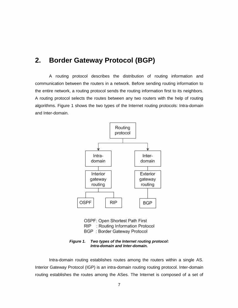
IANA allocates the IP addresses to the Regional Internet Registries (RIRs) in
blocks. From these blocks allocated by the IANA, the local RIRs assign the AS numbers
to the networks. The RIRs assign AS numbers to the ISPs based on their routing
policies. There are five RIRs in the world assigned by the IANA: African Network
Information Centre (AfriNIC) in Africa region, Asia-Pacific Network Information Centre
(APNIC) in Asia Pacific region, Latin America and Caribbean Network Information
Centre (LACNIC) in the Latin American and the Caribbean Islands region, American
Registry for Internet Numbers (ARIN) in North America region, and Réseaux IP
Européens Network Coordination Centre (RIPE) in Europe, Middle East, and Central
Asia region. The growth of ASN assignments per month according to the RIPE registry is
shown in Figure 9.
Figure 9. Growth of the ASN assignments per month by RIPE [31].

16
RIRs separate the address pool based on regions and allocate them to the local
ISPs. The ISP assigns a range of the IP addresses to its users. The flowchart for the
allocation of AS numbers is shown in Figure 10.
Figure 10. Flowchart of allocation of the ASes by the IANA.
The allocation of AS numbers in blocks to RIRs by the IANA is shown in Figure
11. The maximum number of blocks is allocated to the RIPE registry while the minimum
number of blocks is allocated to the AFRINIC registry.

17
Figure 11. Allocation of the AS numbers to RIRs by the IANA.
The ASes are categorized into three types based on the routing policies and
connectivity. These are transit, stub, and multihomed AS. A transit AS maintains its
connection with multiple ASes and helps exchange traffic between two ASes. A transit
AS advertises the customer routes to other ISPs. For example, the ISPs are transit ASes
that allow other ASes to send traffic. A stub AS maintains a connection with only one
transit AS and sends or receives data from another AS only through the connected
transit AS. The ASes in a stub network have no information about the ASes in other stub
networks. A stub AS has a smaller degree of connectivity compared to a transit AS. The
APNIC router reported 224,622 routes on June 30, 2007. These routes arrived from
25,577 ASes, of which only 74 were transit ASes and 22,272 were stub ASes. A
multihomed AS maintains its connections with multiple ASes in the network. A
multihomed AS does not exchange traffic between two ASes. A network with the transit,
stub, and multihomed ASes is shown in Figure 12.

18
Figure 12. A network with the transit, stub, and multihomed ASes.

19
3. Dynamic Behavior of BGP
Social networking and mobile technologies are critical to the growth of the
Internet. In past decade, the Internet experienced tremendous growth. Currently, the
Internet relies mostly on the dynamic routing protocols. For inter-domain routing, the
Internet employs the dynamic nature of BGP. The BGP routers exchange a large
number of update messages due to the continuous changes in the Internet. For
example, the destination may become unavailable due to a router or link failure in the
network. Hence, the BGP routing tables experience continuous transformations. The
dynamic nature of BGP allows the BGP routers to change routing information in their
routing tables as many times as the feasible routes change. The BGP routers
dynamically:
• learn the best route
• route the data to the destination
• update routing information to the neighboring routers.
BGP examines the update messages in: the decision and the update-sent
processes. During the decision process, the BGP router chooses the best route among
the new routes that are received from the other neighboring routers. The decision
process delays processing of the update messages. This delay is called the processing
delay. The update-sent process updates the BGP routers with the new routing
information. The time during which the network learns the best way to reach the
destination and converges is termed the BGP convergence time. In this thesis, we are
particularly interested in this dynamic characteristic of BGP.
3.1. Initiating BGP Routes
BGP learns of the routing information for a route from a BGP router. A BGP
router gets the routing information of a route from IGP and the neighboring ASes. Any

20
change in the network creates a new update in the RIB, which updates the BGP routing
table. A BGP router allocates the DoP to all routes received from the neighboring routers
within the BGP decision process. BGP also updates the RIB with the routing information
of the withdrawn routes. A withdrawn route is an old route to the destination that
becomes unavailable. BGP operates over TCP and an update message is received after
establishing the connection. When an update message is received, the BGP update
format is checked. If the new possible path is indicated in an update message, then the
new path is entered into Adj-RIB-In. Five types of cases may occur:
1. After receiving a new path, the BGP router checks the NLRI. The BGP router will replace the old route that is already stored in the Adj-RIB-In if the NLRI of the new path is the same as the old path. The old path is then withdrawn from the network and BGP sends updates about this path withdrawal to all neighboring BGP routers that are present in the path. After withdrawal, the old route becomes unavailable and the BGP router runs its decision process.
2. If the new received path defines a larger prefix than the old path, then the new path replaces the old path that is already stored in the Adj-RIB-In. After the withdrawal of the old path, the BGP router runs its decision process.
3. If the new received path defines a smaller prefix than the old path, then the BGP router rejects the new path and runs its decision process on the old path.
4. If the new received path describes the same route parameters and the same AS path attributes, then the old path is replaced by the new path in Adj-RIB-In. BGP does not take any additional actions after replacing the path.
5. The new received path replaces the old path in the Adj-RIB-In if the new path has the new NLRI that does not exist in the old path in the Adj-RIB-In.
6. If the withdrawn route field in the BGP update message format contains the unfeasible route, then all IP addresses in the withdrawn route are discarded from the Adj-RIB-In.
3.2. BGP Decision Process
The selection of the local database, updating the BGP routers, and selection of
routers is undertaken during the decision process. After the selection of routes, the
decision process updates the RIB with new routing information and sends routing

21
information to all neighbors. The decision process selects the routes based on the DoP
of the route. The DoP of each path is calculated individually and the path with the
highest DoP value is preferred. The decision process of BGP consists of three phases,
as shown in Figure 13.
Figure 13. Flowchart of the BGP decision process.
Phase 1: After receiving a new route from the neighboring BGP routers, the BGP
decision process calculates the DoP of each new route. This phase allocates a DoP
value to each route while the paths are assigned preference levels based on the DoP
values. The route with the highest preference level is advertised to all neighboring BGP
routers within the AS.
Phase 2: After receiving the preference levels of all routes, in this phase the
decision process entails the selection of the best path to send a packet to the
destination. After selecting the best path, the Loc-RIB is updated with the new routing
information.
Phase 3: After updating the Loc-RIB with new information, the decision process
runs its next phase for the distribution of a new route. The routing information of a new
route is distributed among the BGP routers in the neighboring ASes.

22
A BGP router does not run its decision process if a single path is received. BGP
distributes this received path among the neighboring BGP routers. However, in a
realistic network, a BGP router receives many paths for a single destination. Hence, it is
very essential to choose the best route among several routes for sending data fast to the
destination.
3.2.1. Phase 1: BGP Calculation of DoP
When a BGP router receives the update messages from other BGP routers in the
neighboring ASes, BGP considers this phase as one within the decision process. After
receiving updates of the new or withdrawn route, BGP begins processing the phase one.
During this time, BGP does not update the Adj-RIB-In. The phase one decision process
calculates the DoP of each new, replaced, and withdrawn route. BGP then updates the
Adj-RIB-In with DoP of all routes. The DoP depends on:
1. The local route that originates from the local AS with the highest value of the local preference (LOCAL_PREF) attribute is given the highest priority. The default value for LOCAL_PREF attribute is 100. Each route is assigned a preference value in the update messages upon sending it to the neighboring routers. This attribute is used to reduce traffic and is based on the routing policies configured in the network.
2. The DoP of the route that originated from the BGP router in the neighboring AS is calculated based on the routing policies among the ASes. The ASes with the same configured routing policies are given the highest priority.
3. If the decision process assigns the same DoP to two paths, then phase one applies the tie-breaker to these two paths. For example, according to one tie-breaker, the DoP of a path depends on the number of ASes between the source and the destination BGP routers. The path with the smallest number of ASes between the source and destination is given the highest priority.
3.2.2. Phase 2: BGP Route Selection
BGP processes its phase two of the decision process after computing the DoP of
the routes in phase one. While operating the received updates, the phase two decision
process locks the Adj-RIB-In. After acting on all update messages, it unlocks the Adj-
RIB-In. The phase two analyzes the BGP NEXT_HOP attribute. For any route, if the
NEXT_HOP attribute represents the IP address that is not present in the Loc-RIB, the

23
route may be discarded. Similarly, based on the NEXT_HOP attribute all other
unfeasible routes may be discarded in this phase. Among the feasible paths, the BGP
router in this phase identifies:
• selected path that has the highest DoP among other paths;
• selected path that is the only available path;
• selected path that has the highest DoP because of the tie-breaker.
After the selection of the feasible path to the destination, the decision process
updates the new routing information in the Loc-RIB. If a new path replaces an old path in
the Loc-RIB, the updates with the route withdrawal are sent to the neighboring ASes.
If the path changes due to network failure, then the BGP router analyzes the
NEXT_HOP attribute agian. The old unfeasible path is withdrawn and replaced by a new
path in the Loc-RIB. After removing the path from the Loc-RIB, the unfeasible path is
also removed from the Adj-RIB-In.
3.2.3. Phase 3: BGP Route Dissemination
Phase three of the decision process is processed after phase two. Phase three
stops working if phase two is underway. It also starts processing when the Loc-RIB
changes after:
• a change in the local path to the destination.
• a change in the path to the destination because of change in the neighboring ASes.
• the arrival of a new route to the destination.
The final feasible routes are updated in the Adj-RIB-Out from the Loc-RIB in
phase three. After updating the Adj-RIB-Out, the BGP routers update the Forwarding
Information Base (FIB). After the completion of phase 3, the BGP router runs the
external update process by disseminating the routing information to the BGP routers in
the neighboring ASes.

24
3.2.4. An example of the Cisco Router
BGP is widely employed in the Cisco routers. When a new route arrives to the
BGP Cisco router, the routers run their decision process and choose the best route
using the following algorithm:
1. A BGP router assigns the highest priority to the path with the highest WEIGHT attribute. This is the Cisco defined attribute and is allocated locally to the router.
2. A BGP router assigns the highest priority to the path with the highest LOCAL_PREF attribute.
3. A BGP router assigns the highest priority to the path with the shortest AS_PATH attribute.
4. A BGP router assigns the highest priority to the path with the smallest origin attribute, which specifies the origin of a routing update.
5. A BGP router assigns the highest priority to the path with the smallest Multi-exit Discriminator (MED) value. The MED value attribute is defined by Cisco.
6. A BGP router assigns the highest priority to the eBGP routes over the interior Border Gateway Protocol (iBGP) routes.
7. If the paths have equal preference value, then a BGP router assigns the highest priority to the path that was received first.
8. A BGP router assigns the highest priority to the route that originates from the router with the smallest ID.
9. If two different routes have the same preference level and the routers from where these two paths originate have the same router ID, then the Cisco router assigns priority to the route with the smallest cluster list length. This step is applicable only to BGP route reflector (RR) environments, which permits clients to peer with other clusters or with RRs.
10. A BGP router assigns the highest priority to the path that originates from the smallest IP address.
3.3. BGP Convergence Time
The state of a group of routers that have the same network topological
information in which they operate is called convergence [3], [4]. The routers in a network
learn topological information from the neighboring routers via BGP. This topological
information should be same as any other router's topology information in the group. All

25
routers in a converged network agree on the current state of the network. The state of
convergence is complete when the routing information is distributed to all routers
participating in the routing protocol process. The change in routing information may be
caused by the network failure or the arrival of the new best routes to the destination.
When BGP processes an advertisement, all routers in the path to the destination
exchange routing information about the network. The new, old, or withdrawn path in a
network changes the routing tables and breaks the convergence temporarily until the
new routing information has been successfully communicated to all other routers. The
routers should agree on the routing information in order to achieve the convergence.
Convergence is achieved when the routing information gets exchanged successfully
among all routers without any change in the network. If a network experiences a network
change, the routing information in the routers also changes and this affects the
convergence process. The time required for routes to become stable after a change in
the routing information and the network converges is called the BGP convergence time.
It is a measure of how fast a group of routers reaches the state of convergence. In
dynamic routing, convergence is a significant state for a group of routers in a network.
All routing protocols rely on the convergence process.
The main goal of BGP is to deliver the packets to the destination as fast as
possible. To achieve this goal, BGP needs to converge fast. The BGP convergence time
depends how fast the set of routers achieves the state of convergence after a network
failure. When there are cyclic loops in the path, there is a non-zero probability that
convergence will never be achieved [32]. Furthermore, the BGP convergence time also
depends on the network size and number of neighboring nodes. A network with a small
number of ASes converges very quickly compared to a network with hundreds of ASes.
However, if the number of neighboring nodes is not constant then there will be a very
large number of update messages exchanged in the network and a network may take
few minutes to converge [26]. The main features that may limit the BGP convergence
time are the MRAI delay, routing table size, processing delay, and route flap damping
[33]. Route flap damping controls the frequency of update messages caused by a link or
path failure in the network. In route flap damping, a route is first advertised, then
withdrawn, and then re-advertised. Route flap damping decreases the processing load

26
on BGP routers by reducing the overall number of BGP update messages exchanged
within the network [5].
For a specific network topology, there is an optimal MRAI value that reduces the
BGP convergence time [3]. The duration of MRAI equal to 0 s may increase the BGP
convergence time and the number of update messages [3]. Longer durations of MRAI
may also increase the BGP convergence time [33]. There is an optimal range of MRAI
values. A BGP router may require time for discovering all feasible routes to the
destination. A BGP router sends a route advertisement for each route it considers to be
the best route. An MRAI timer is associated with each route sent and the previous timers
may delay the other advertisements until the MRAI round ends. Hence, a network may
require several MRAI rounds to converge.
Along with the network size, the length of convergence time depends on the
traffic volume in the network and number of hops to the destination. The convergence
time also depends on the BGP path exploration procedure. In a completely connected
network with n ASes, BGP needs a minimum of (n-3) rounds [34] of the MRAI timer for
the lower bound on BGP convergence. The situations that lead to the worst BGP
convergence are [34]:
• all ASes in a complete graph have a degree of (n-1).
• one update message is permitted to be sent at a time and all other subsequent update messages in the queue are sent one-by-one.
• duplicate update messages are sent before other update messages.
3.4. MRAI Timers
A BGP router may receive different update messages from different neighboring
routers in order to reach the same destination. A BGP router runs its decision process
on all received update messages and selects the best route to reach the destination. A
BGP router may not receive the best route instantaneously. If a BGP router
instantaneously responds to the received update messages, it may increase the BGP
convergence time by selecting a non-optimal path [3]. Hence, a BGP router has to wait
in order to achieve the best route to reach a destination. However, a BGP router cannot
27
wait long because this may also increase the BGP convergence time. When a BGP
router sends advertisements to its neighboring routers, the interval that defines the
minimum duration of time between two subsequent advertisements of the same
destination is called the MRAI.
During the MRAI, the BGP router may receive many update messages and it
may also run its decision process several times based on the received update
messages. While running the decision process during an MRAI, the BGP router does not
reveal the information regarding all received update messages to its neighboring routers.
This decreases the overall number of update messages, which may consequently result
in reduced BGP convergence time [4]. After selecting the best path during an MRAI, a
BGP router distributes the new routing information to all neighboring routers. Hence, the
MRAI prevents the network from being overwhelmed with update messages. It also
prevents a BGP router from responding immediately. The MRAI implemented in routers
within the same AS increases the BGP convergence time. Hence, the MRAI is not
recommended within the AS.
The MRAI for the unfeasible routes also increases the BGP convergence time.
Hence, the MRAI is not recommended for the withdrawn route messages [1]. However,
the recent BGP specification recommends that the MRAI limit should be applied to the
withdrawal route messages. The duration of the MRAI is limited by the MRAI timer and is
equal to 30 s [1]. The Cisco routers are configured with an MRAI of 30 s while the
Juniper routers are configured with an MRAI of 0 s [6]. Different companies may use
different values of the MRAI round depending on the configured routing policies with the
customers. For example, if two ASes have the customer-provider routing policy
relationships, they will not wait for an optimal path to send a packet to destination.
However, there should be a limitation on advertisements interval to achieve the optimal
path. The MRAI is applied on the per-destination basis. However, the value of MRAI is
allocated on a per-peer basis [1].
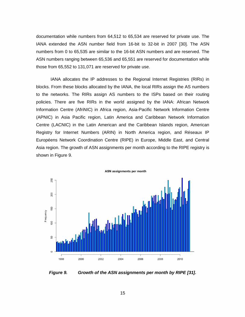
3.4.1. Per-Destination MRAI Timer
In a per-destination MRAI timer, one timer is associated with one destination.
The routers need not to wait for an MRAI to send an advertisement to the destination.

28
The per-destination timers independently limit the rate for all destinations. Furthermore,
the per-destination timers have to keep the additional information about the destination
and this may also increase the overhead. The core Internet router may contain millions
of destinations and, hence, it may not be realistic to implement a large number of timers.
We illustrate the use of timers in a simple network of four ASes shown in Figure
14. AS1 and AS2 send their advertisements to AS4 through AS3. We assume that AS1
advertises the 10.1.0.0/24 address and that AS2 advertises the 10.2.0.0/24 address.
Figure 14. Example of a network with four ASes to illustrate the use of timers.
AS3 advertises 10.1.0.0/24 to AS4 when it receives route 10.1.0.0/24 from AS1, as
shown in Figure 15. If AS3 suddenly receives route 10.2.0.0/24 from AS2, it advertises
10.2.0.0/24 to AS4 immediately without waiting for expiration of the previous MRAI timer.
The per-destination MRAI timers send advertisements of different destinations
independently.

29
Figure 15. Illustration of a per-destination timer.
3.4.2. Per-Peer MRAI Timer
The per-peer MRAI timers are recommended in RFC 1771 [1]. One timer is
associated with each peer. Irrespective of the destination, a per-peer MRAI timer starts
when an advertisement is sent to one of its neighbors. The per-peer MRAI timers also
help the peers by ensuring that the advertisements of the same destinations do not
overwhelm them. The number of per-peer MRAI timers required in a network is equal to
the total number of peers. Hence, it is feasible to implement the per-peer MRAI timers in
the Internet. However, due to the previous update messages for other destinations, an
advertisement for a new destination may be delayed by the MRAI.
AS3 receives 10.1.0.0/24 from AS1 and then advertises 10.1.0.0/24 to AS4, as
shown in Figure 14. Later, if AS3 receives 10.2.0.0/24 from AS2, it does not advertise
10.2.0.0/24 to AS4 immediately. AS3 waits for the expiration of the previous MRAI timer
and holds the advertisement sent by AS2. After the previous MRAI timer expires, AS3

30
checks the routing table and advertises 10.2.0.0/24 to AS4 that was on hold. Hence, AS3
delays 10.2.0.0/24 until the end of the previous MRAI round, as shown in Figure 16.
Figure 16. Illustration of a per-peer timer.
3.5. BGP Processing Delay
The main reasons for the fast growth of the BGP routing tables are a heavy load
of update messages, the occurrence of multihoming networks, and load balancing [35].
These factors lead to the growth of the BGP routing table size, which results in the
processing delays [36]. The processing delay includes the time required for BGP to route
the packet and the queuing time of the packet. A BGP router imposes delay on an
update message if there are other update messages in the queue. The processing delay
also depends on the network size and volume of network traffic.
The processing of the update messages als depends n the r uter’s C U. The
high utilization of CPU implies that the CPU is busy with other jobs such as the
processing and holding of other BGP update messages. Hence, high utilization of CPU

31
may lead to delays in the processing of subsequent update messages in the queue.
Most BGP routers use first-in-first-out (FIFO) queues for receiving the update messages.
When the update message enters the FIFO queue, a message is delayed based on the
r uter’s w r l ad.
The uniform BGP processing delay model has been implemented in the SSFNET
[3] and the ns-BGP [5] simulators. In case of the uniform BGP processing delays, the
impact of the router workload on BGP is defined by a parameter called workload
induced-delay, which is independently imposed on each update message. The uniform
BGP processing model calculates the total processing time for each update message.
The total delay of an update message is the sum of its workload induced-delay and the
workload induced-delay of all other BGP update messages that were in the queue when
this update message arrived. Hence, the processing of each BGP update message in
the queue affects the processing of newly received update message, as shown in Figure
17.
Figure 17. A model of the uniform BGP processing delay.
The estimation of the processing delay of each BGP update message is
analyzed by using CPU delay ranging between pmin = 0.01 s and pmax = 1 s [6]. For a set
of n update messages in the queue, the average processing delay tpd is:
tpd = n * [pmax – pmin] /2 . (1)

32
The average BGP processing delay based on measurements is much smaller
than the expected uniform processing delay [6]. The BGP routers send sets of update
messages in 200 ms processing cycles. If the CPU utilization of a BGP router is below
the maximum levels, then a BGP router may process majority of the received update
messages at the end of a 200 ms processing cycle. The measurements show that
approximately 95% of the update messages are sent within the 200 ms processing
cycle.

33
4. FLD-MRAI Algorithm
4.1. CPU Utilization and Processing Delay
In the proposed FLD-MRAI algorithm, we use an empirical value of 200 ms for
the processing delay. The FLD-MRAI algorithm processes update messages within 200
ms rounds and it operates in the case of both normal and high network loads. When
DoP is the shortest path, then FLD-MRAI assumes a normal load scenario. When DoP is
the longer path in the presence of the shortest path based on certain conditions, then
FLD-MRAI assumes a high load scenario. We assume that all received update
messages are processed within a single processing round. The source BGP router
sends an advertisement of destination address D to the neighboring BGP routers at time
to. After advertising a destination, the source BGP router begins receiving path-updates
from the neighboring BGP routers. The MRAI consists of two states: idle and processing.
The source BGP router prioritizes the received update messages and assigns the
highest priority to the update with the shortest path. A critical factor in the processing
delay is to estimate CPU time needed to send update messages. If one task demands
higher CPU utilization, then the router dedicates fewer CPU cycles to the remaining
tas s. When a r uter’s C U utilizati n is high, then the r uter resp nds sl wly t
subsequent requests in the queue. The BGP router calculates available CPU of the
neighboring routers based on the priority of update messages. The percentage of
available CPU CPUavailable of the neighboring router is calculated as:
CPUavailable = 100 - CPUactive (2)
CPUactive = 100 * (CPUcurrent/CPUmax), (3)
where CPUactive is the percentage of active CPU utilization of the neighboring router,
CPUcurrent is the current CPU utilization, and CPUmax is the maximum CPU utilization. To
count the available CPU of a neighboring BGP router, the percentage of CPU utilization

34
of the neighboring router during active period is subtracted from a total of 100%. The
active CPU utilization of a neighboring router is equal to the fraction of the current CPU
utilization and the maximum CPU elapsed time. The maximum CPU elapsed time is
always equal to or greater than the current C U utilizati n time. I the r uter’s queue is
empty, then the maximum CPU elapsed time is equal to the current CPU utilization time.
The value of CPUavailable is calculated by a BGP router and sent to the neighboring BGP
routers along with other BGP attributes during the update-sent process.
At the beginning of the BGP decision process, a router calculates the DoP of
each new, replaced, and/or withdrawn route [1]. The default DoP depends on:
• The local routes that originate from the local AS and have the LOCAL_PREF value equal to 100 are given the highest priority. The route having the shortest path is called Routeinfo.
• The default DoP of a route is subject to the routing policies among the ASes. The ASes having the same routing policy are given the highest priority.
In the proposed FLD-MRAI algorithm, the FLD-MRAI-enabled BGP router
calculates DoP based on the available percentage of CPU. The DoPmod is a function of
Routeinfo and CPUavailable. The implemented FLD-MRAI algorithm does not consider
routing policies for calculating DoP. The routers with higher CPUavailable are given the
highest priority. CPUavailable is calculated every time a router receives the update
message of a new or withdrawn route. The default DoP changes every time a router
receives the new or withdrawn route update message [1]. When an FLD-MRAI-enabled
BGP router sets priorities based on DoP, it always considers the available CPU. A path
with the highest DoPmod value is given the highest priority. The default DoP may also rely
upon other BGP attributes depending on the manufacturers. An example of the Cisco
router BGP attributes is given in Section 3.2.4. However, DoPmod depends on the
available CPU attribute and the shortest path to the destination. The DoPmod is
calculated every time when a router receives a new, old, or replaced path. After
calculating the available CPU, the FLD-MRAI-enabled BGP router compares the
available CPU of the neighboring BGP routers according to priorities based on the
shortest path.

35
Suppose that R1 and R2 are the neighboring BGP routers based on the first and
the second priority paths, respectively. A default BGP router follows the DoP rule to
always prefer the local shortest path to send data and, hence, it selects a path that
includes R1, which belongs to the first priority path. Assume that C1 and C2 are available
CPU of the BGP routers R1 and R2, respectively.
If C1 is larger than C2, then the FLD-MRAI-enabled BGP source router assumes
this scenario as a normal load and follows the shortest path. In the normal load scenario,
DoP remains unchanged and, hence, CPU utilization does not affect the computation of
DoP.
If C1 is smaller than C2, then the FLD-MRAI-enabled BGP source router
calculates the waiting time in the queue of R1 and the transmission time to R2. If the
waiting time is larger than the transmission time, then the FLD-MRAI-enabled BGP
router checks DoP of both paths. If DoP of path including R2 is larger than the DoP of the
path including R1, then the FLD-MRAI-enabled BGP router chooses a second priority
path. Otherwise, it switches back to the first priority path. If the load disperses to the
longer path based on certain conditions of the FLD-MRAI algorithm, then the algorithm
detects this scenario as a high load. FLD-MRAI may be also implemented in networks
where the traffic volume is unspecified. The two load cases of the FLD-MRAI algorithm
are shown in Figure 18. The normal load scenario depends on the advertisement events,
which depend on the network conditions.
Figure 18. Two load scenarios of the FLD-MRAI algorithm.
To illustrate the difference between the FLD-MRAI and the default MRAI [1]
algorithms, we consider a simple network with five routers shown in Figure 19. Suppose
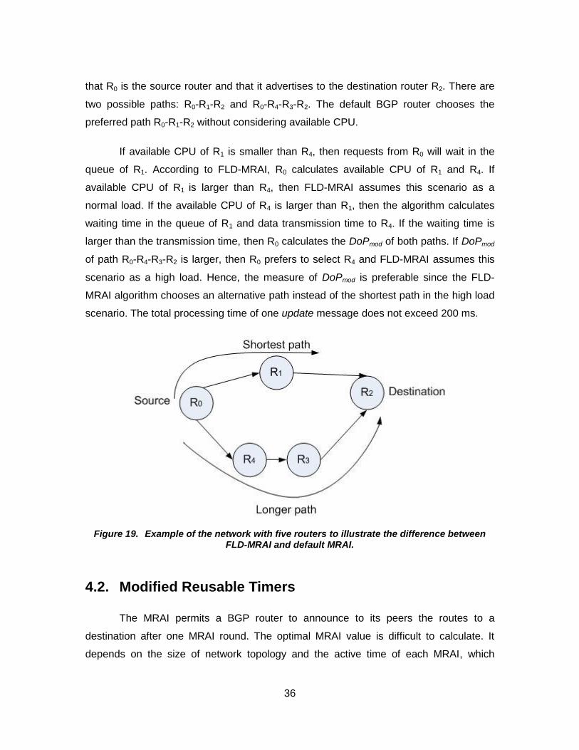
36
that R0 is the source router and that it advertises to the destination router R2. There are
two possible paths: R0-R1-R2 and R0-R4-R3-R2. The default BGP router chooses the
preferred path R0-R1-R2 without considering available CPU.
If available CPU of R1 is smaller than R4, then requests from R0 will wait in the
queue of R1. According to FLD-MRAI, R0 calculates available CPU of R1 and R4. If
available CPU of R1 is larger than R4, then FLD-MRAI assumes this scenario as a
normal load. If the available CPU of R4 is larger than R1, then the algorithm calculates
waiting time in the queue of R1 and data transmission time to R4. If the waiting time is
larger than the transmission time, then R0 calculates the DoPmod of both paths. If DoPmod
of path R0-R4-R3-R2 is larger, then R0 prefers to select R4 and FLD-MRAI assumes this
scenario as a high load. Hence, the measure of DoPmod is preferable since the FLD-
MRAI algorithm chooses an alternative path instead of the shortest path in the high load
scenario. The total processing time of one update message does not exceed 200 ms.
Figure 19. Example of the network with five routers to illustrate the difference between FLD-MRAI and default MRAI.
4.2. Modified Reusable Timers
The MRAI permits a BGP router to announce to its peers the routes to a
destination after one MRAI round. The optimal MRAI value is difficult to calculate. It
depends on the size of network topology and the active time of each MRAI, which
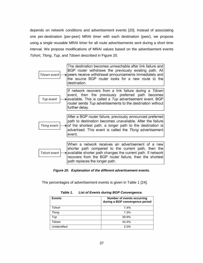
37
depends on network conditions and advertisement events [20]. Instead of associating
one per-destination (per-peer) MRAI timer with each destination (peer), we propose
using a single reusable MRAI timer for all route advertisements sent during a short time
interval. We propose modifications of MRAI values based on the advertisement events
Tshort, Tlong, Tup, and Tdown described in Figure 20.
Figure 20. Explanation of the different advertisement events.
The percentages of advertisement events is given in Table 1 [24].
Table 1. List of Events during BGP Convergence.
Events Number of events occurring during a BGP convergence period
Tshort 7.4%
Tlong 7.3%
Tup 39.9%
Tdown 43.4%
Unidentified 2.0%

38
We identify two categories of advertisement events and proposes two values for
the MRAI timers. The FLD-MRAI algorithm computes the duration of MRAI rounds
individually for each destination. After processing, three events may occur:
• new update message received
• no new update received
• MRAI reusable timer expired.
The time period of MRAI when a BGP router actually processes the received
update messages is called the active time. The remaining period is the idle time. During
each advertisement event, FLD-MRAI calculates the idle time and enters the processing
state. FLD-MRAI calculates the idle time during the initiation of a new round. FLD-MRAI
chooses the duration of the MRAI round based on the duration of the idle time. A long
idle interval during the previous MRAI round may indicate that the active interval is small
and the update has been advertised in a shorter time than the default value. Similarly, a
short idle interval may indicate that the active interval is longer than expected and,
hence, the previous MRAI round should have lasted longer. The idle time Tidle (D) is
calculated as:
Tidle (D) = MRAItotal - Mlast , (4)
where MRAItotal is the total MRAI and Mlast is the time instance of the last message
received. We implement changes in reusable MRAI timers that independently limit
advertisements of many destinations. The main advantage of a reusable timer is that
only one reusable timer is required for all paths advertised during a short time interval.
We propose specific durations of a reusable MRAI timer for different advertisement
events. A single reusable MRAI timer belongs to all route advertisements sent during a
certain (short) time interval. The duration of this interval defines the granularity of the
MRAI round that determines the number of reusable MRAI timers.
An FLD-MRAI-enabled BGP router needs to determine which reusable MRAI
timer is to be associated with a sent route advertisement. For each advertisement, the
last expired reusable timer is used because it enforces an MRAI round to last within a
certain interval. For example, reusable timer 1 starts at 66 s and advertisement 1 sent at
time 66 s is associated with this timer 1, as shown in Figure 21. The duration of MRAI for

39
this advertisement is 96 s (66+30 s). Advertisement 2 sent at 66.3 s is also associated
with the timer 1. Advertisement 2 will last for 29.7 s. All other advertisements sent
between 66 s and (66 + 1) s are also associated with the timer 1.
Figure 21. All advertisements sent between 66 s and 67 s are associated with the same reusable timer.
The number of rounds per reusable MRAI timer controls the duration of MRAI
round MRAIduration calculated as:
MRAIduration = Rn * (Tn * g) , (5)
where Rn is the number of rounds per reusable MRAI timer, Tn is the number of reusable
MRAI timers, and g is the granularity. The reusable MRAI timer is associated with each
route advertisement sent. The timers need to store pointers that are required only for
non-converged routes. Hence, the overhead of storing pointers is minimal. When an
MRAI timer expires, the reusable timers keep a list of paths that need to be advertised.
4.3. Duration of MRAI
It is essential to analyze the duration of the MRAI timers for BGP advertisement
events [20], [24]. Since the BGP convergence time for a Tlong or a Tdown event is
larger than for a Tshort or a Tup event, we propose a longer duration of MRAI timers for
the Tlong and Tdown events and a smaller duration for the Tshort and Tup events. The

40
MRAI value for the Tlong and Tdown events and for the Tshort and Tup events are
identical. In case of FLD-MRAI with granularity 1 s, the proposed minimum duration is 15
s. The idle time is calculated as the longest interval between two update messages in an
MRAI round. The threshold for determining the minimum idle period is set to 1 s, which
is identical to the granularity of the MRAI rounds.
If the FLD-MRAI-enabled BGP router detects the idle time longer than 1 s, then it
would process the received update message during the time interval well before the
expiration of a timer. Two types of advertisement events may occur: Tshort or Tup. In
both cases, the previously announced shortest preferred route to the destination
becomes available. Tshort occurs on arrival of a new shortest path update or after the
recovery of the BGP router failure while Tup occurs after a link failure recovery. The
FLD-MRAI-enabled BGP router sends update messages to the destination in case of
both advertisement events without further delay. We propose a duration of MRAI round
equal to 15 s for these two events.
If the FLD-MRAI-enabled BGP router detects the idle time shorter than 1 s, then
the router had processed the received update message during the time interval very
close to the timer expiration. Two types of advertisement events may occur: Tlong or
Tdown. In both cases, the previously announced shorter preferred route to the
destination becomes unavailable. Hence, the BGP router withdraws the updates in both
events and announces longer paths compared to the previously preferred paths. Thus,
the duration of MRAI timer should be larger. We propose duration of MRAI round of 30 s.
Hence, the FLD-MRAI-enabled BGP router doubles the value of the MRAI round for
these events. The reusable timer automatically adjusts its duration to 30 s by using two
MRAI rounds of 15 s without expiration of the reusable timer after the first 15 s round.
After the expiration of the second round, FLD-MRAI assigns one round for the reusable
timer (15 s). The maximum period of the MRAI round is equal to the default MRAI value
(30 s). If the shortest path becomes available during a Tlong or Tdown event, then the
FLD-MRAI-enabled BGP router withdraws the current update. After the expiration of two
rounds of reusable timer, the FLD-MRAI-enabled BGP router chooses the shortest path
with duration of one round (15 s). The default value of MRAI is 30 s [1] and a previous
study proposes MRAI of 15 s [10]. However, we propose durations of MRAI based on
various advertisement events.

41
If network conditions change due to a path or BGP router failure during Tshort or
Tup events, then the event changes to Tlong or Tdown. After the expiration of the
reusable timer, the FLD-MRAI-enabled BGP source router chooses a second priority
path and uses reusable timer twice. Hence, the proposed algorithm processes the Tlong
and Tdown updates with default duration of MRAI (30 s), while the Tshort and Tup
updates use half of the default MRAI duration (15 s). The advertisements during the
Tshort and Tup events experience shorter delay and, hence, decrease the BGP
convergence time.
The duration of the MRAI round may be 15 s or 30 s based on the computation of
the idle time. After the expiration of each reusable timer, the timer may be used again
and its duration may vary. We use 15 timers with granularity 1 s and change value of the
number of rounds (one or two). FLD-MRAI assigns two rounds for a reusable timer with
30 s duration (Tlong or Tdown). If the FLD-MRAI-enabled BGP router does not receive
update message of the current destination within the previously described MRAI period,
then we assume that the routes have converged.
An illustrative example is shown in Figure 22 where each of the 15 reusable
MRAI timers with granularity 1 s takes one round during the time interval of 15 s. Timer0
lasts one round of 15 s. After expiration, it is reused as Timer15. If Timer2 updates occur
during Tlong or Tdown, then the duration of the MRAI round is set to 30 s. After
expiration, Timer2 is reused as Timer32 whose duration depends on the idle time.
Figure 22. Fifteen reusable timers with MRAI rounds equal to 15 s or 30 s.
To illustrate usage of reusable timers consider four cases of advertisement
events, as shown in Figure 23 to Figure 26.

42
4.3.1. Tshort /Tup update after another Tshort /Tup update
The reusable Timer1 lasts one MRAI round of duration 15 s and granularity 1 s,
as shown in Figure 23. It starts at 10.0 s and expires after 15 s. The reusable Timer1 is
used again after 15 s for another advertisement at 25.0 s. After the expiration of Timer1
(at 25.0 s), the FLD-MRAI-enabled BGP router calculates the idle time and if the idle
time is longer than 1 s, then the reusable MRAI Timer1 will be set again to last 15 s with
granularity 1 s. The Timer1 will expire after 15 s (at 40.0 s).
Figure 23. Timer1 is reused after 15 s for the next Tshort /Tup update.
4.3.2. Tshort /Tup update after a Tlong/Tdown update
The reusable Timer1 lasts two MRAI rounds each of 15 s (total duration 30 s), as
shown in Figure 24. It starts at 10.0 s and expires after 30 s. The reusable Timer1 is
used again after 30 s for another advertisement at 40.0 s. After the expiration of Timer1
(at 40.0 s), the FLD-MRAI-enabled BGP router calculates the idle time. If the idle time is
longer than 1 s, then the reusable Timer1 will be set to last 15 s with one MRAI round.
The Timer1 will expire after 15 s (at 55.0 s).

43
Figure 24. Timer1 is reused after 30 s for the next Tshort /Tup update.
4.3.3. Tlong/Tdown update after a Tshort /Tup update
The reusable Timer1 lasts one MRAI round of 15 s, as shown in Figure 25. It
starts at 10.0 s and expires after 15 s. The reusable Timer1 is used again after 15 s for
another advertisement at 25.0 s. After the expiration of reusable Timer1 (at 25.0 s), the
FLD-MRAI-enabled BGP router calculates the idle time. If the idle time is shorter than 1
s, then, the reusable Timer1 will be set to 30 s with two MRAI rounds each lasting 15 s.
The Timer1 will expire after 30 s (at 55.0 s). If there is no update at 55.0 s after the
expiration of Timer1, the duration of Timer1 is by default set back to 15 s. If there are
update messages, then the FLD-MRAI-enabled BGP router will calculates the idle time
and adjust the duration of MRAI round accordingly.
Figure 25. Timer1 is reused after 15 s for the next Tlong/Tdown update.
4.3.4. Tlong/Tdown update after another Tlong/Tdown update
The reusable Timer1 takes two MRAI rounds each of 15 s (total duration 30 s), as
shown in Figure 26. It starts at 10.0 s and expires after 30 s. The reusable Timer1 is

44
used again after 30 s for another advertisement at 40.0 s. After the expiration of Timer1
(at 40.0 s), the FLD-MRAI-enabled BGP router calculates the idle time. If the idle time is
shorter than 1 s, then the reusable Timer1 will be set again to 30 s and it will expire at
70.0 s. After the expiration of Timer1, if there is no update at 70.0 s, then the duration of
reusable MRAI Timer1 is by default set back to 15 s.
Figure 26. Timer1 is reused after 30 s for the next Tlong/Tdown update.
4.4. Space and Time Complexity of the FLD-MRAI Algorithm
The space complexity is the number of memory cells that an algorithm requires.
The FLD-MRAI algorithm changes the routing path only when an update of a better route
to the destination is received. Hence, the algorithm depends on the number of non-
converged routes n during a period of the MRAI. The implementation of the FLD-MRAI
algorithm requires that the router keeps three variables for each non-converged route:
CPUcurrent, CPUmax, and Mlast. These variables are integer counters that a router may
easily store. The space complexity of the FLD-MRAI algorithm is O(n).
The time complexity counts the amount of time taken by an algorithm to run its
operations as a function of input size n. The time complexity of the FLD-MRAI algorithm
is equal to the number of processes executed at the beginning of the MRAI round, as
shown in Figure 27. At the initiation of a new MRAI round, the algorithm recalculates the
idle time for each new advertisement received.

45
When sending advertisement of the destination D to peers at to set (Si) // priority numbers on received updates according to the shortest path if (C1< C2) // calculate and compare the available CPU of the neighboring routers if W(t) < T(t) // calculate and compare the waiting and transmission times else (wait in queue of the first priority path) if dop2 < dop1 // calculate and compare the degree of preference choose the second priority path MRAI = 30 s goto processing state else (wait in queue of the first priority path) else if (C1> C2) wait in queue of the first priority path // duration of MRAI is based on the idle time goto processing state
when initiation of the new round
if (Idle(D) > 1 s) // Tshort or Tup may occur set modified_reusable timer = 15 s
else if (e ∈ network failure) // events change due to the network failure choose the second priority path // after expiration of the timer set modified_reusable timer = 30 s goto processing state
else if (eÏnetwork failure)
goto processing state else if (Idle(D) < 1 s) // Tlong or Tdown may occur set modified_reusable timer = 30 s
else if (Pt ∈ Ps) // if the shortest path becomes available choose the shortest path // after expiration of the timer set modified_reusable timer = 15 s goto processing state
else (PtÏPs) // if the shortest path is not available
goto processing state
Figure 27. Pseudocode of the proposed FLD-MRAI algorithm.
The FLD-MRAI algorithm requires divisions, multiplications, and subtractions.
The division and multiplication operations are used in calculation of CPUavailable, Tidle, and
MRAIduration. The time complexity of the division and multiplication depends on input size
n while the time complexity of the subtraction is constant. The maximum value of
MRAIduration is 30 s. To simplify estimation of the time complexity, we approximate these
variables with constants equal to their maximum values. This establishes the upper
bound of time complexity. We may assume that divisions and multiplications used in
calculation of variables do not depend on input size n. The computation of CPUavailable
requires one subtraction, one multiplication, and one division (3). The computation of
Tidle requires one subtraction while MRAIduration requires two multiplications. Hence, the
time complexity of the computation of these variables at the beginning of the FLD-MRAI
algorithm is O(n).

46
The BGP router may send only one advertisement and one withdrawal during a
single MRAI round. The number of the neighbors and non-converged routes during one
MRAI round affect the maximum number of update messages. The time complexity to
compute the idle time is O(n) if the number of the neighbors is constant.

47
5. Implementation of the FLD-MRAI Algorithm
We implement the FLD-MRAI algorithm using the ns-2.34 network simulator and
the ns-BGP 2.0 [5] developed module.
5.1. Ns-2 Implementation
Ns-2 is a network simulator used to evaluate the network performance by creating the
network topologies by using both the analytical and simulation system modeling
approaches [37]. The analytical modeling approach describes a system mathematically
and then applies numerical methods to understand results from the developed
mathematical model. This approach is feasible only in simple and small systems.
However, the simulation approach is feasible in the complex and large systems. Ns-2
was developed in both object-oriented TCL (Otcl) and C++ language. Otcl is a user
interface language where a user may define a network topology while C++ is a
simulation interface language used to run the actual simulations. The class hierarchies
of Otcl and C++ may be either standalone or connected together using an interface
called TclCL, as shown in Figure 28.
Figure 28. The structure of ns-2 with two languages: C++ and Otcl [37].
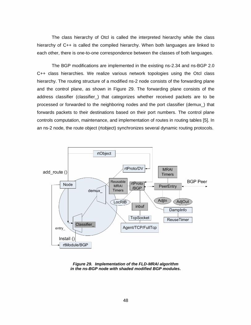
48
The class hierarchy of Otcl is called the interpreted hierarchy while the class
hierarchy of C++ is called the compiled hierarchy. When both languages are linked to
each other, there is one-to-one correspondence between the classes of both languages.
The BGP modifications are implemented in the existing ns-2.34 and ns-BGP 2.0
C++ class hierarchies. We realize various network topologies using the Otcl class
hierarchy. The routing structure of a modified ns-2 node consists of the forwarding plane
and the control plane, as shown in Figure 29. The forwarding plane consists of the
address classifier (classifier_) that categorizes whether received packets are to be
processed or forwarded to the neighboring nodes and the port classifier (demux_) that
forwards packets to their destinations based on their port numbers. The control plane
controls computation, maintenance, and implementation of routes in routing tables [5]. In
an ns-2 node, the route object (rtobject) synchronizes several dynamic routing protocols.
Figure 29. Implementation of the FLD-MRAI algorithm in the ns-BGP node with shaded modified BGP modules.

49
The ns-BGP node shown in Figure 29 contains the following modules:
Agent/TCP/FullTcp, TcpSocket, rtProto/BGP, rtModule/BGP, PeerEntry, AdjIn, AdjOut,
LocRIB, and MRAI timers. The rtModule/BGP, Agent/TCP/FullTcp, and TcpSocket have
been added to the ns-2 routing structure to establish the Ipv4 addressing and to
accomplish compatibility with the SSFNET implementation of BGP [5].
The C++ class rtProto/BGP performs most BGP operations:
• Displays all routes in the LocRIB and AdjRIBIn;
• Sets manual configurable values for BGP. If the ‘autoconfig’ attribute is set in the TCL script file, then in eBGP sessions all default values are used for all neighboring BGP routers;
• Adds and removes a route to the local forwarding table;
• Handles update, withdrawal, and a new route;
• Calculates the DoP of a route. It is a non-negative integer. The higher values indicate the preferable routes;
• Receives and handles both externally and internally generated BGP events;
• Establishes the BGP connections;
• Determines the best route and manages the BGP finite state machine.
The C++ class PeerEntry stores information about each peer connection and
contains two routing tables: AdjRIBIn and AdjRIBOut. The AdjRIBIn stores the NLRI
exchanged between BGP routers learned from a neighboring BGP. The AdjRIBOut
stores the NLRI exchanged between BGP routers, which are to be announced to a
neighboring BGP.
The shaded areas in Figure 29 are new or modified to implement the FLD-MRAI
algorithm in ns-BGP. To implement the FLD-MRAI algorithm, we modify reusable timers,
DoP, rtProto/BGP, and address classifier (classifier_). We also use an empirical value of
the processing delay, which is implemented in the input buffer (inbuf_). FLD-MRAI
computes the percentage of available CPU and the duration of MRAI rounds for each
destination in rtProto/BGP. Furthermore, it computes the value of DoP for paths in the
address classifier (classifier_). FLD-MRAI stores the update messages and forwards
them to the port classifier (demux_) after computing the available CPU of the
neighboring BGP routers. An expired reusable timer is used again in the BGP decision
process that is associated with rtProto/BGP.

50
5.2. Implementation Features
The modified DoP, computation of available CPU, duration of MRAI, and
modified reusable timers are features of the FLD-MRAI algorithm that have been
implemented in an existing BGP model (ns-BGP). These features are interconnected
with each other. We may simply turn ON/OFF the FLD-MRAI algorithm switch in C++
rtprotoBGP class. If the FLD-MRAI algorithm switch in rtprotoBGP class is turned ON,
then the modified reusable timers will be used and the modified DoP will be computed
automatically. Furthermore, the cpu_timer feature should also be turned ON for
calculating the available CPU. Other features such as global_MRAI and
continuous_timer should be turned OFF.
5.3. Simulation Scenarios
Various network topologies have been used for the performance evaluation of
the FLD-MRAI algorithm. We compare performance of the FLD-MRAI algorithm with
FLD-MRAI having MRAI of 30 s (FLD-MRAI-30) or 15 s (FLD-MRAI-15) for all
advertisement events. We also compare the FLD-MRAI algorithm with the original BGP
having MRAI of 30 s (default-MRAI-30) and 15 s (default-MRAI-15) and the adaptive
MRAI [2]. Four parameters were considered when designing simulation scenarios:
network size, network traffic, BGP events, and total simulation time. The simulation time
depends on simulation parameters.
We limit the network size to 500 nodes because of the limited memory of the TCL
script. Most previous studies of the BGP convergence time do not exceed the network
size of 110 nodes [3], [22], [23], [38]–[40]. Only one study [41] used 500 nodes for
evaluation of the BGP convergence time.
5.4. Simulation Topologies
We evaluate the proposed FLD-MRAI algorithm using topologies derived from
the BCNET BGP traffic collection [42], the Georgia Tech Internetwork Topology Models

51
(GT-ITM) generator [43], and the Boston university Representative Internet Topology
gEnerator (BRITE) [44]. Five network topologies are listed in Table 2.
Table 2. Network Topologies used in Simulations.
Topology Number of nodes Topology generator
Topology 1 67 Manually from BCNET BGP traffic
Topology 2 100 GT-ITM
Topology 3 200 GT-ITM
Topology 4 400 BRITE
Topology 5 500 BRITE
5.4.1. Network Topology 1
Network Topology 1 consists of 67 nodes built manually from the collection of
BCNET BGP traffic [45], [46]. BCNET delivers the Ipv4 and Ipv6 routed services and
high-speed ptical ad anced netw r t British C lumbia’s higher educati n and
research institutes called the Optical Regional Advanced Network (ORAN) [42]. BCNET
supports 10 Gbps Ethernet network with backup of 1 Gbps links designed in ease of
quick failure and provides both point-to-point and point-to-multipoint transparent Ethernet
services. The transit sources are linked to BCNET via 1 Gbps and 10 Gbps network
links. The BCNET network is high-speed fiber optic research network that permits
remote research, virtual laboratories, high-definition videoconferencing, distant learning,
large-scale data transfers, and distributed computing. It is also used to convey the
Internet communication, telephone signals, and cable television signals. To utilize its full
transmission capacity, BCNET is mainly connected for the long-distance applications.
The BCNET transit exchanges contain the network interconnections that employ peering
between links. Peering needs a physical link and an interchange of routing information
over BGP. The BCNET balances the enlarged Internet transit cost and increases
network implementation due to high-speed fiber network, local peering, and multi-hoping
services. The BCNET network provides up to 72 wavelengths of capacity at 10 Gbps
and links to 140 provincial universities and institute campus sites, research services,
regional health centers, central and regional research labs, and academic schools that
practice the provincial learning network. It is also connected to the network association
called Canada’s Ad anced Research and Inn ati n Netw r (CANARIE), which
associates Canada and the United States over the Internet. CANARIE also connects

52
Canada to Europe through the Delivery of Advanced Network Technology to Europe
(DANTE) [42].
We examine the routing tables of the BCNET BGP traffic and analyze AS
numbers and the connections between Ases. The connection of links was generated
from the BCNET BGP traffic. An example of the BGP routing table updates used for
generating the network Topology 1 is shown in Table 3. We can identify the source IP
address 207.23.253.2 (AS 271) and it is advertising to the destination (AS 1221). The
source AS receives updates of all possible paths. From the AS path list, we can identify
the neighboring links between Ases. For example, Ases 6327 and 6453 are neighbors of
the source AS 271 and Ases 56203, 2519,18144, 4725, and 38345 are neighbors of AS
1221. We restrict the size of network Topology 1 to 67 nodes due to memory constraints.
Table 3. Example of BCNET BGP routing table updates.
Time Peer’s IP Peer’s AS Source IP AS Path
2011-10-24, 05:18 216.6.50.9 6327 207.23.253.2 6327-7575-56203-1221
2011-10-24, 05:18 207.23.253.34 6453 207.23.253.2 6453-2914-2519-1221
2011-10-24, 05:18 216.6.50.9 6327 207.23.253.2 6327-2516-2519-1221
2011-10-24, 05:18 207.23.253.34 6453 207.23.253.2 6453-4725-7670-18144-1221
2011-10-24, 05:18 216.6.50.9 6327 207.23.253.2 6327-2516-7670-18144-1221
2011-10-24, 05:18 207.23.253.34 6453 207.23.253.2 6453-4725-1221
2011-10-24, 05:18 216.6.50.9 6327 207.23.253.2 6327-4725-1221
2011-10-24, 05:18 207.23.253.34 6453 207.23.253.2 6453-2914-4641-38345-1221
2011-10-24, 05:18 216.6.50.9 6327 207.23.253.2 6327-2914-4641-38345-1221
5.4.2. Network Topology 2 and Topology 3
Network Topology 2 and Topology 3 were generated using the GT-ITM
generator. The GT-ITM generates topologies based on three models: flat random, N-
level hierarchy, and transit-stub hierarchical. Topologies consisting of 100 and 200
nodes were generated using transit-stub hierarchy for two reasons: the transit-stub
m del matches t day’s Internet t p l gy and has a precise hierarchical c n igurati n
comparable to the Internet tiers that allow a provider to divide traffic into separate levels
[47]. The Ases in a stub network have no information about the Ases in other stub
networks. The Ases exchange traffic between stub networks through the transit Ases.
They have a smaller degree of connectivity compared to a transit AS. The GT-ITM

53
generator initially creates a connected random graph in order to create a transit-stub
model topology where each node signifies a transit AS. Every node in the transit AS is
connected to the stub AS. Networks may be linked using any of the six graph connection
methods: Doar-Leslie, Exponential, Waxman1, Waxman2, Locality, or PureRandom [43].
We generate topologies using the PureRandom method. Furthermore, extra transit Ases
and stub Ases may also be added to the network topology. Number of nodes in a
generated topology is calculated as [47]:
N = T*Nt*[1+(K*Ns)] , (6)
where T is fully connected transit domain, Nt is the average number of nodes per transit
AS, K is the average number of stub Ases per transit AS, Ns is the average number of
nodes per stub AS, N is the total number of nodes. The values used for the parameters
to create a 100-node and 200-node topology are given in Table 4.
Table 4. Values of parameters for 100-node and 200-node topologies.
Symbols 100-node topology 200-node topology
T 1 1 Nt 4 8 K 3 4 Ns 8 6 N 100 200
Number of nodes in the 100-node topology is:
N = 1*4*[1+(3*8)]
N = 100.
Number of nodes in the 200-node topology is:
N = 1*8*[1+(4*6)]
N = 200.
5.4.3. Network Topology 4 and Topology 5
Network Topology 4 and Topology 5 were generated using the topology
generator BRITE [44], which generates different types of Internet topologies from models
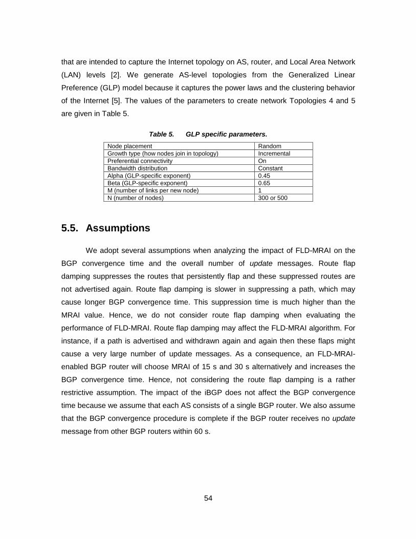
54
that are intended to capture the Internet topology on AS, router, and Local Area Network
(LAN) levels [2]. We generate AS-level topologies from the Generalized Linear
Preference (GLP) model because it captures the power laws and the clustering behavior
of the Internet [5]. The values of the parameters to create network Topologies 4 and 5
are given in Table 5.
Table 5. GLP specific parameters.
Node placement Random
Growth type (how nodes join in topology) Incremental
Preferential connectivity On
Bandwidth distribution Constant
Alpha (GLP-specific exponent) 0.45
Beta (GLP-specific exponent) 0.65
M (number of links per new node) 1
N (number of nodes) 300 or 500
5.5. Assumptions
We adopt several assumptions when analyzing the impact of FLD-MRAI on the
BGP convergence time and the overall number of update messages. Route flap
damping suppresses the routes that persistently flap and these suppressed routes are
not advertised again. Route flap damping is slower in suppressing a path, which may
cause longer BGP convergence time. This suppression time is much higher than the
MRAI value. Hence, we do not consider route flap damping when evaluating the
performance of FLD-MRAI. Route flap damping may affect the FLD-MRAI algorithm. For
instance, if a path is advertised and withdrawn again and again then these flaps might
cause a very large number of update messages. As a consequence, an FLD-MRAI-
enabled BGP router will choose MRAI of 15 s and 30 s alternatively and increases the
BGP convergence time. Hence, not considering the route flap damping is a rather
restrictive assumption. The impact of the iBGP does not affect the BGP convergence
time because we assume that each AS consists of a single BGP router. We also assume
that the BGP convergence procedure is complete if the BGP router receives no update
message from other BGP routers within 60 s.

55
6. Performance Evaluation
6.1. Validation tests
Tests are performed in order to validate the implemented modifications in ns-
BGP. The tested network topologies include a five nodes topology and a completely
connected topology with fifteen nodes.
6.1.1. Network Topology with five Nodes
The FLD-MRAI algorithm is validated by using a simple network of five routers.
The working of the FLD-MRAI algorithm is explained theoretically and experimentally by
using this simple network.
6.1.1.1. Theoretical Explanation
We consider a simple example of five routers, as shown in Figure 30. R0 is a
source router and R2 is a destination router. Since there are two possible paths R0-R1-R2
and R0-R4-R3-R2, we consider two scenarios with FLD-MRAI: normal load and high load.
Figure 30. Example of the possible paths in the network of five routers.

56
Scenario 1: FLD-MRAI with the Normal Load Scenario
If available CPU of R1 is larger than R4, then FLD-MRAI-enabled BGP router R0
assumes a normal load scenario. Thus, FLD-MRAI has the same DoP of paths as the
original BGP. Hence, FLD-MRAI also selects the shortest path R0-R1-R2 and processes
the update message within 200 ms. In the normal load scenario, four cases may occur:
1. If R1 fails, the shortest path (R0-R1-R2) is withdrawn and the second priority path (R0-R4-R3-R2) will be selected. This event is considered as Tlong and the duration of MRAI round is set to 30 s.
2. If the shortest path R0-R1-R2 becomes available, the longer path (R0-R4-R3-R2) is then withdrawn and the shortest path is selected. This event is considered as Tshort and the duration of MRAI round is set to 15 s.
3. If the link between R0 and R1 fails, the shortest path (R0-R1-R2) is then withdrawn and the second priority path is selected. This event is considered as Tdown and the duration of MRAI round is set to 30 s.
4. If the link failure between R0 and R1 recovers, the longer path (R0-R4-R3-R2) is then withdrawn and the shortest path is selected. This event is considered as Tup and the duration of MRAI round is set to 15 s.
Scenario 2: FLD-MRAI with the High Load Scenario
If available CPU of R1 is smaller than R4, then FLD-BGP-enabled BGP router R0
assumes a high load scenario. Hence, FLD-MRAI-enabled BGP router R0 prefers path
(R0-R4-R3-R2), as shown in Figure 31. However, a default BGP router always prefers the
shortest path (R0-R1-R2) and waits in the queue of R1. In the high load scenario, the
duration of MRAI round is set to be 30 s and, hence, the reusable timer is used twice.
Figure 31. Example of the high load scenario in the shortest path of the network with five routers.

57
6.1.1.2. Experimental evaluation
We tested the employed modifications in ns-BGP for both normal and high loads.
For the validation test, the topology with the minimum number of nodes is used to
analyze the BGP convergence time for all BGP events (Tshort, Tlong, Tup, and Tdown)
and the high load. The BGP convergence time of both scenarios with FLD-MRAI is
compared to default-MRAI-30. A topology with five nodes shown in Figure 32 is used for
validation test. The node 0 is a source node and node 2 is a destination node. Two
possible paths from the source to the destination are: n0-n1-n2 and n0-n4-n3-n2. The
default BGP router prefers the shortest path n0-n1-n2. In simulation scenario of the Tlong
event, n1 fails and it recovers in the simulation scenario of the Tshort event. In simulation
scenario of the Tdown event, the link between n0 and n1 fails and it recovers in
simulation scenario of the Tup event. We apply high traffic load to n1 in the high load
scenario. After detecting the high load, n0 follows the longer path n0-n4-n3-n2.
Figure 32. Ns-nam graph of a network with five nodes.
The TCL scripts for the validation tests of the normal and high loads are listed in
Appendix A. The BGP convergence times for both FLD-MRAI and default-MRAI-30 are
given in Table 6. Simulation results indicate that FLD-MRAI performs as expected.

58
Table 6. Average Convergence Time for 5 Nodes Topology for Different BGP Options.
Scenarios default-MRAI-30 (s) FLD-MRAI (s)
Tshort 88.70 52.70
Tlong 93.10 71.59
Tup 88.60 55.50
Tdown 93.05 60.90
High load 102.91 56.81
6.1.2. Completely Connected Network Topology with fifteen Nodes
To validate performance of the FLD-MRAI algorithm using various network
topologies, we also compare simulation results of the convergence time and the number
of update messages with results reported in previous studies. We choose the completely
connected network with fifteen nodes, as shown in Figure 33. The TCL script for the
validation tests of the completely connected network is listed in Appendix B.
Figure 33. Completely connected network with fifteen nodes.
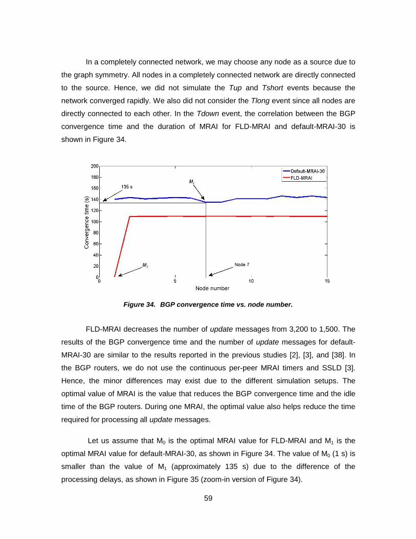
59
In a completely connected network, we may choose any node as a source due to
the graph symmetry. All nodes in a completely connected network are directly connected
to the source. Hence, we did not simulate the Tup and Tshort events because the
network converged rapidly. We also did not consider the Tlong event since all nodes are
directly connected to each other. In the Tdown event, the correlation between the BGP
convergence time and the duration of MRAI for FLD-MRAI and default-MRAI-30 is
shown in Figure 34.
Figure 34. BGP convergence time vs. node number.
FLD-MRAI decreases the number of update messages from 3,200 to 1,500. The
results of the BGP convergence time and the number of update messages for default-
MRAI-30 are similar to the results reported in the previous studies [2], [3], and [38]. In
the BGP routers, we do not use the continuous per-peer MRAI timers and SSLD [3].
Hence, the minor differences may exist due to the different simulation setups. The
optimal value of MRAI is the value that reduces the BGP convergence time and the idle
time of the BGP routers. During one MRAI, the optimal value also helps reduce the time
required for processing all update messages.
Let us assume that M0 is the optimal MRAI value for FLD-MRAI and M1 is the
optimal MRAI value for default-MRAI-30, as shown in Figure 34. The value of M0 (1 s) is
smaller than the value of M1 (approximately 135 s) due to the difference of the
processing delays, as shown in Figure 35 (zoom-in version of Figure 34).

60
Figure 35. Optimal value of MRAI for an empirical BGP processing delay.
The smaller processing delay is directly proportional to the optimal value of the
MRAI. The MRAI values larger than optimal have a linear relationship to the BGP
convergence time, as shown in Figure 34. The same linear relationship between the
BGP convergence time and the duration of the MRAI is found in previous studies [2], [3],
and [38]. Therefore, simulation results of FLD-MRAI agree with previous simulations
and, hence, implementation of the FLD-MRAI algorithm may be deemed correct. Figure
34 also illustrates that MRAI values larger than M1 increase the BGP convergence time.
Moreover, a BGP router cannot converge immediately without waiting until the end of the
processing cycle.

61
6.2. Network Topology 1
The network Topology 1 is generated by the routing tables of the BCNET BGP
traffic data. We consider two simulation scenarios: normal load and high load. The
convergence times are obtained by placing the origin router at a particular location in the
network. Changing the location of the origin router may lead to the different convergence
times.
6.2.1. FLD-MRAI with the Normal Load Scenario
In this scenario, we consider four cases: Tshort, Tlong, Tup, and Tdown. The
source node begins sending traffic at 30.0 s and at 130.0 s.
Tshort event: Majority of the BGP routers with default-MRAI-30 require
approximately four MRAI rounds to find the best route. However, majority of the FLD-
MRAI-enabled BGP routers require approximately three MRAI rounds, resulting in an
average BGP convergence time of approximately 67 s. In this case, node 3 recovers
from failure and, hence, it has a high convergence time, as shown in Figure 36.
Simulation results show that the source node 1 and nodes that are connected to only
one node in the network have shorter convergence time. Results also show that the
convergence times of FLD-MRAI-15 and FLD-MRAI are shorter than FLD-MRAI-30.
Hence, using FLD-MRAI with MRAI of 15 s in case of the Tshort event decreases the
convergence time.

62
Figure 36. Convergence time for network Topology 1 for the Tshort event.
Tlong event: The current path is replaced with the longer path when the shorter
path becomes unavailable. Most BGP routers with default-MRAI-30 need approximately
five MRAI rounds to find the best route. Conversely, most FLD-MRAI-enabled BGP
routers need approximately three MRAI rounds to find the best route, resulting in an
average BGP convergence time of approximately 77 s. Simulation results also show that
FLD-MRAI-30 performs similarly to FLD-MRAI in case of the Tlong event, as shown in
Figure 37. Hence, using FLD-MRAI with MRAI of 30 s in case of the Tlong event
decreases the convergence time.
Figure 37. Convergence time for network Topology 1 for the Tlong event.

63
Tup event: After some time an unreachable destination becomes available and
some BGP routers first send update messages to the non-optimal paths, which affects
the BGP convergence time. Most BGP routers with default-MRAI-30 need approximately
four MRAI rounds to obtain the best route. However, majority of FLD-MRAI-enabled
BGP routers need approximately two MRAI rounds to obtain the best route, resulting in
an average BGP convergence time of approximately 65 s. Simulation results show that
using FLD-MRAI with MRAI of 15 s in case of the Tup event decreases the convergence
time, as shown in Figure 38.
Figure 38. Convergence time for network Topology 1 for the Tup event.
Tdown event: The reachable destination becomes unreachable and after the
expiration of the current MRAI round, a BGP router chooses another path. Simulation
results show that using FLD-MRAI with MRAI of 30 s in case of the Tdown event
decreases the convergence time, as shown in Figure 39. Most BGP routers with default-
MRAI-30 require approximately five MRAI rounds to obtain the best route. However,
majority of the FLD-MRAI-enabled BGP routers require approximately two MRAI rounds
to get the best route, resulting in an average BGP convergence time of approximately 75
s.
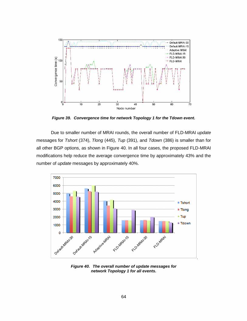
64
Figure 39. Convergence time for network Topology 1 for the Tdown event.
Due to smaller number of MRAI rounds, the overall number of FLD-MRAI update
messages for Tshort (374), Tlong (445), Tup (391), and Tdown (386) is smaller than for
all other BGP options, as shown in Figure 40. In all four cases, the proposed FLD-MRAI
modifications help reduce the average convergence time by approximately 43% and the
number of update messages by approximately 40%.
Figure 40. The overall number of update messages for network Topology 1 for all events.

65
6.2.2. FLD-MRAI with the High Load Scenario
If the load disperses to a longer path due to DoP, then FLD-MRAI considers this
scenario as a high load. According to default DoP, the source router will follow the
shortest path even in the case of high load and the request will wait in the queue of the
neighboring router. However, in case of FLD-MRAI, the source router follows the path
having large available CPU. The BGP convergence time depends on the length of routes
from the origin to other BGP routers. In the case of the high load scenario, we repeat
simulations using different nodes as the origin. The source node sends traffic at 200.0 s
and at 730.0 s. The majority of the BGP routers with default-MRAI-30 require 39 MRAI
rounds to obtain the best route, resulting in an average BGP convergence time of
approximately 1,192 s. However, majority of the FLD-MRAI-enabled BGP routers require
25 MRAI rounds to obtain the best route, resulting in an average BGP convergence time
of approximately 765 s, which is smaller than the adaptive MRAI and default-MRAI-15
times, as shown in Figure 41.
Figure 41. Convergence time for network Topology 1 for the high load scenario.
FLD-MRAI performs better than FLD-MRAI-30 and FLD-MRAI-15 and reduces
the average convergence time by 36%. The network has to wait for many MRAI rounds
to converge due to the high load of update messages. However, an FLD-MRAI-enabled
BGP router changes its path according to available CPU and BGP converges within few
MRAI rounds. FLD-MRAI reduces the number of overall update messages by 70%, from

66
14,911 to 4,526. Hence, for the high load scenario, the FLD-MRAI algorithm performs
better than other BGP options, as shown in Figure 42.
Figure 42. The overall number of update messages for network Topology 1 for the high load scenario.
6.2.3. Summary of Network Topology 1
Summary of the average BGP convergence times and the number of update
messages received during the period of convergence are shown in Table 7 and Table 8.
Table 7. Average Convergence Time for 67 Nodes Topology for Different BGP Options.
Scenarios default-MRAI-30 (s)
default-MRAI-15 (s)
adaptive MRAI (s)
FLD-MRAI-15 (s)
FLD-MRAI-30 (s)
FLD-MRAI (s)
Tshort 126.66 145.29 131.90 68.73 69.40 66.93
Tlong 138.47 143.81 142.62 79.60 78.45 77.07
Tup 126.39 145.50 132.02 66.03 67.80 65.33
Tdown 138.52 145.62 141.40 75.86 74.73 74.73
High load 1,192.07 1,192.21 1,047.42 767.62 782.62 764.63
Table 8. Overall Number of Update Messages for 67 Nodes Topology for Different BGP Options.
Scenarios default-MRAI-30
default-MRAI-15
adaptive MRAI
FLD-MRAI-15
FLD-MRAI-30
FLD-MRAI
Tshort 726 1,304 870 375 374 373
Tlong 608 1,073 1,142 452 456 445
Tup 681 1,262 763 399 420 391
Tdown 673 1,251 751 394 415 386
High load 14,911 27,566 12,362 10,094 10,549 4,526

67
6.3. Network Topology 2
Network Topology 2 consists of 100 nodes and is generated by the GT-ITM
generator. Simulation results for both normal and high load scenarios are shown in
Table 9 and Table 10.
6.3.1. FLD-MRAI with the Normal Load Scenario
The source node begins sending traffic at 130.0 s and 830.0 s. Node 45 is a
source node and it advertises the destination node 72. The shortest path in the topology
from the source to the destination is 45-44-1-3-2-69.
Table 9. Average Convergence Time for 100 Nodes Topology for Different BGP Options.
Scenarios default-
MRAI-30 (s) default-
MRAI-15 (s) adaptive MRAI (s)
FLD-MRAI-15 (s)
FLD-MRAI-30 (s)
FLD-MRAI (s)
Tshort 854.02 845.34 849.98 770.99 894.47 770.70
Tlong 880.30 865.79 864.40 783.19 801.66 779.93
Tup 853.52 845.01 849.63 776.56 810.83 770.98
Tdown 853.80 845.64 850.038 861.51 888.60 771.06
High load 524.00 423.54 520.90 377.50 427.92 374.00
Table 10. Overall Number of Update Messages for 100 Nodes Topology for Different BGP Options.
Scenarios default-MRAI-30
default-MRAI-15
adaptive MRAI
FLD-MRAI-15
FLD-MRAI-30
FLD-MRAI
Tshort 2,472 2,475 1,906 1,836 2,093 1,725
Tlong 2,728 2,748 2,089 1,755 1,772 1,687
Tup 2,469 2,472 1,905 1,943 2,049 1,738
Tdown 2,469 2,456 1,905 1,932 2,133 1,728
High load 20,605 24,056 21,528 17,867 17,349 16,087
Tshort event: The failed node 3 in the shortest path (45-44-1-3-2-69) recovers
and the shortest path becomes available. The network then discards the longer path and
prefers the shortest path. FLD-MRAI requires twenty-five MRAI rounds to find the best
route. FLD-MRAI decreases the BGP convergence time from 854 s to 770 s when
compared to default-MRAI-30.
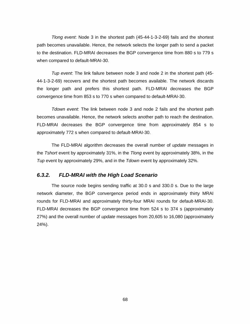
68
Tlong event: Node 3 in the shortest path (45-44-1-3-2-69) fails and the shortest
path becomes unavailable. Hence, the network selects the longer path to send a packet
to the destination. FLD-MRAI decreases the BGP convergence time from 880 s to 779 s
when compared to default-MRAI-30.
Tup event: The link failure between node 3 and node 2 in the shortest path (45-
44-1-3-2-69) recovers and the shortest path becomes available. The network discards
the longer path and prefers this shortest path. FLD-MRAI decreases the BGP
convergence time from 853 s to 770 s when compared to default-MRAI-30.
Tdown event: The link between node 3 and node 2 fails and the shortest path
becomes unavailable. Hence, the network selects another path to reach the destination.
FLD-MRAI decreases the BGP convergence time from approximately 854 s to
approximately 772 s when compared to default-MRAI-30.
The FLD-MRAI algorithm decreases the overall number of update messages in
the Tshort event by approximately 31%, in the Tlong event by approximately 38%, in the
Tup event by approximately 29%, and in the Tdown event by approximately 32%.
6.3.2. FLD-MRAI with the High Load Scenario
The source node begins sending traffic at 30.0 s and 330.0 s. Due to the large
network diameter, the BGP convergence period ends in approximately thirty MRAI
rounds for FLD-MRAI and approximately thirty-four MRAI rounds for default-MRAI-30.
FLD-MRAI decreases the BGP convergence time from 524 s to 374 s (approximately
27%) and the overall number of update messages from 20,605 to 16,080 (approximately
24%).

69
6.4. Network Topology 3
Network Topology 3 consists of 200 nodes and is also generated by the GT-ITM
generator. Simulation results for both normal and high load scenarios are shown in
Table 11 and Table 12.
6.4.1. FLD-MRAI with the Normal Load Scenario
The source node begins sending traffic at 70.0 s. Node 136 is the source node
and it advertises the destination node 191. The shortest path in the topology from the
source to the destination is 136-138-140-101-103-102-188-187-191.
Table 11. Average Convergence Time for 200 Nodes Topology for Different BGP Options.
Scenarios default-MRAI-30 (s)
default-MRAI-15 (s)
adaptive MRAI (s)
FLD-MRAI-15 (s)
FLD-MRAI-30 (s)
FLD-MRAI (s)
Tshort 84.98 76.47 81.95 71.99 80.55 71.81
Tlong 97.32 82.40 81.86 77.46 86.01 77.51
Tup 84.97 76.46 81.86 71.97 80.54 71.81
Tdown 85.03 76.52 90.66 72.00 80.57 71.99
High load 947.17 413.03 912.39 566.88 677.49 544.03
Table 12. Overall Number of Update Messages for 200 Nodes Topology for Different BGP Options.
Scenarios default-MRAI-30
default-MRAI-15
adaptive MRAI
FLD-MRAI-15
FLD-MRAI-30
FLD-MRAI
Tshort 768 766 756 714 708 631
Tlong 1,019 1,029 1,020 711 705 644
Tup 763 765 756 710 704 640
Tdown 768 763 756 715 709 650
High load 93,782 32,003 31,585 42,879 41,084 29,104
Tshort event: The network recovers from the node 103 failure and the shortest
path becomes available. FLD-MRAI decreases the BGP convergence time from 84 s to
71 s when compared to default-MRAI-30.
Tlong event: Node 103 fails and the shortest path to the destination becomes
unavailable. FLD-MRAI decreases the BGP convergence time from 98 s to 77 s when
compared to default-MRAI-30.

70
Tup event: The network recovers the link failure between node 103 and node 101
and the shortest path becomes available. FLD-MRAI decreases the BGP convergence
time from 85 s to 71 s when compared to default-MRAI-30.
Tdown event: The shortest path becomes unavailable when the link between
node 103 and node 101 fails. FLD-MRAI decreases the BGP convergence time from
approximately 84 s to approximately 72 s when compared to default-MRAI-30.
FLD-MRAI decreases the overall number of update messages in the Tshort and
Tdown events by approximately 16%, the Tlong event by approximately 37%, and the
Tup event by approximately 17%.
6.4.2. FLD-MRAI with the High Load Scenario
The source node begins sending traffic at 70.0 s. Due to the large network
diameter, the BGP convergence period ends in approximately sixteen MRAI rounds for
the FLD-MRAI and approximately thirty-two MRAI rounds for the default-MRAI-30. FLD-
MRAI decreases the BGP convergence time from 947 s to 544 s (approximately 43%)
and the overall number of update messages from 93,782 to 29,104 (approximately
68%).

71
6.5. Network Topology 4
Network Topology 4 consists of 300 nodes and is generated by the topology
generator BRITE. Simulation results for both normal and high load scenarios are shown
in Table 13 and Table 14.
6.5.1. FLD-MRAI with the Normal Load Scenario
The source node begins sending traffic at 300.0 s and 1,000.0 s. Node 49 is
source node and it advertises the destination node 139.
Table 13. Average Convergence Time for 300 Nodes Topology for Different BGP Options.
Scenarios default-MRAI-30 (s)
default-MRAI-15 (s)
adaptive MRAI (s)
FLD-MRAI-15 (s)
FLD-MRAI-30 (s)
FLD-MRAI (s)
Tshort 603.30 599.21 546.57 457.11 466.66 452.77
Tlong 602.08 597.41 543.26 459.76 468.23 455.47
Tup 617.19 604.74 554.24 456.41 465.64 452.13
Tdown 601.99 597.37 549.80 611.99 599.28 454.70
High load 545.73 540.55 494.41 569.31 543.39 200.93
Table 14. Overall Number of Update Messages for 300 Nodes Topology for Different BGP Options.
Scenarios default-MRAI-30
default-MRAI-15
adaptive MRAI
FLD-MRAI-15
FLD-MRAI-30
FLD-MRAI
Tshort 5,026 5,654 4,085 1,611 1,614 1,506
Tlong 4,648 5,279 3,458 1,610 1,620 1,505
Tup 5,365 6,026 4,217 1,597 1,611 1,492
Tdown 4,602 5,233 3,100 2,905 2,020 1,331
High load 5,753 6,326 4,675 5,135 4,974 1,344
Tshort event: The network recovers from node 6 failure and the shortest path
becomes available. Simulation results for the Tshort event for the BGP convergence
show that FLD-MRAI decreases the average BGP convergence time by approximately
25%.
Tlong event: After node 6 fails, the shortest path to the destination becomes
unavailable. Simulation results for the Tlong event show that with FLD-MRAI, the
average BGP convergence time is reduced by approximately 24%.

72
Tup event: The shortest path becomes available when network recovers the link
failure between node 6 and node 1. Simulation results for the Tup event show that FLD-
MRAI decreases the average BGP convergence time by approximately 26%.
Tdown event: The shortest path becomes unavailable when the link between
node 6 and node 1 fails. Simulation results for the Tdown event show that FLD-MRAI
reduces the average BGP convergence time by approximately 25%.
FLD-MRAI decreases the overall number of update messages in the Tshort
event by approximately 70%, in the Tlong event by approximately 68%, in the Tup event
by approximately 72%, and the Tdown event by approximately 71%.
6.5.2. FLD-MRAI with the High Load Scenario
The source node begins sending traffic at 200.0 s and 900.0 s. The BGP
convergence period takes approximately six MRAI rounds for FLD-MRAI and
approximately eighteen MRAI rounds for default-MRAI-30. FLD-MRAI decreases the
BGP convergence time from 546 s to 201 s (approximately 64%) and the overall number
of update messages from 5,753 to 1,344 (approximately 77%). Simulation results show
that FLD-MRAI performs better than other BGP options.

73
6.6. Network Topology 5
Network Topology 5 consists of 500 nodes and is generated by the topology
generator BRITE.
6.6.1. FLD-MRAI with the Normal Load Scenario
The source node begins sending traffic at 500.0 s and 1,200.0 s. Node 39 is a
source node and it advertises the destination node 120.
Tshort event: Node 0 in the shortest path recovers from failure and the shortest
path becomes available. Simulation results for the Tshort event are shown in Figure 43.
When FLD-MRAI with MRAI of 30 s (FLD-MRAI-30) is used, the network suffers from the
high convergence time. One possible reason may be the small active time during Tshort
event. FLD-MRAI with MRAI of 15 s shows better convergence time. Results also show
that FLD-MRAI decreases the average BGP convergence time by approximately
23.23%.
Figure 43. Convergence time for network Topology 5 for the Tshort event.
Tlong event: Node 0 in the shortest path fails and the shortest path becomes
unavailable. Simulation results for the Tlong event are shown in Figure 44. The average

74
BGP convergence time is reduced by 24.00%. Simulation results also show that using
FLD-MRAI with MRAI of 30 s decreases the convergence time. The reason is that a
BGP router will search for other feasible routes to the desired destination when a route is
withdrawn.
Figure 44. Convergence time for network Topology 5 for the Tlong event.
Tup event: When the failed link between the node 0 and node 5 recovers, the
shortest path to the destination becomes available. Simulation results for the Tup event
are shown in Figure 45. Results show that FLD-MRAI decreases the average BGP
convergence time by 23.32%. FLD-MRAI with MRAI of 15 s helps decrease the
convergence time.

75
Figure 45. Convergence time for network Topology 5 for the Tup event.
Tdown event: When the link between node 0 and node 5 fails, the shortest path
to the destination becomes unavailable. Simulation results for the Tdown event are
shown in Figure 46. The average BGP convergence time is reduced by 23.20%. In this
case, FLD-MRAI with MRAI of 30 s helps decrease the convergence time. Due to a link
failure, a BGP router will try all feasible routes to the destination until it finds the best
path. The process of path exploration depends on the number of feasible paths that the
BGP router has maintained for the destination.
Figure 46. Convergence time for network Topology 5 for the Tdown event.

76
FLD-MRAI reduces the overall number of update messages in the Tshort event
by approximately 69%, in the Tlong event by approximately 70%, in the Tup event by
approximately 71%, and the Tdown event by approximately 69%, as shown in Figure 47.
FLD-MRAI decreases the average BGP convergence time by approximately 23% and
the overall number of update messages by approximately 70% for all events.
Figure 47. The overall number of update messages for network Topology 5 for all events.
6.6.2. FLD-MRAI with the High Load Scenario
The source node begins sending traffic at 300.0 s and 1,400.0 s. As the number
of network nodes increases, the volume of traffic and the number of feasible paths to a
destination increases. The BGP convergence period takes approximately seventeen
MRAI rounds for FLD-MRAI and takes approximately 31 MRAI rounds for default-MRAI-
30. The proposed modifications help reduce the average convergence time from 918 s
to 530 s (approximately 57%), as shown in Figure 48 and the number of update
messages from 13,353 to 2,672 (approximately 80%), as shown in Figure 49.
Simulations results show that FLD-MRAI performs better than other BGP options. The
FLD-MRAI algorithm performs even better in networks with large number of nodes.
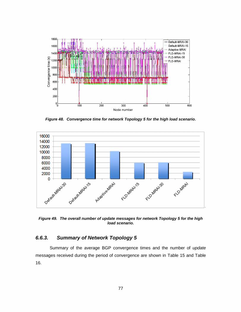
77
Figure 48. Convergence time for network Topology 5 for the high load scenario.
Figure 49. The overall number of update messages for network Topology 5 for the high load scenario.
6.6.3. Summary of Network Topology 5
Summary of the average BGP convergence times and the number of update
messages received during the period of convergence are shown in Table 15 and Table
16.

78
Table 15. Average Convergence Time for 500 Nodes Topology for Different BGP Options.
Scenarios default-MRAI-30 (s)
default-MRAI-15 (s)
adaptive MRAI (s)
FLD-MRAI-15 (s)
FLD-MRAI-30 (s)
FLD-MRAI (s)
Tshort 772.91 775.71 782.42 659.90 792.67 601.50
Tlong 795.61 778.60 783.26 794.67 660.66 608.66
Tup 773.03 775.65 782.34 659.66 793.05 602.51
Tdown 796.13 779.60 784.71 794.46 661.09 609.33
High load 918.02 909.48 906.42 930.95 951.70 530.39
Table 16. Overall Number of Update Messages for 500 Nodes Topology for Different BGP Options.
Scenarios default-MRAI-30
default-MRAI-15
adaptive MRAI
FLD-MRAI-15
FLD-MRAI-30
FLD-MRAI
Tshort 8,330 12,298 6,526 6,342 7,755 2,579
Tlong 8,349 12,286 6,514 6,315 7,721 2,564
Tup 8,323 12,292 6,520 6,331 7,734 2,523
Tdown 8,326 12,286 6,526 6,315 7,721 2,565
High load 13,353 13,422 10,466 6,141 6,256 2,672

79
7. Future Work
The study of the BGP convergence time and the number of exchanged update
messages depends on many factors. The effect of iBGP and eBGP on the convergence
time and the number of update messages may also be analyzed. In simulations, the
effect of iBGP may be detected by including additional BGP nodes. Simulation results
imply that performance of the BGP convergence time depends on traffic volume, type of
network topology, and network size. Hence, different simulation scenarios of network
topology and various BGP attributes such as traffic intensity may also be analyzed.
Different durations of the Tshort and Tup events may also be examined. Other topology
generators may also be used to create and analyze topologies different from those
presented in this thesis. BGP has been implemented in deployed and large networks.
Instead of simulations, it would be beneficial to test the FLD-MRAI algorithm in a real
test-bed by using minimum of five FLD-enabled BGP routers. Constant repetition of the
advertisement and withdrawal of routes due to circumstances such as broken
communication links or variable links may lead to route flapping within the network.
Route flap damping increases the BGP convergence time and number of update
messages in the network. Route flap damping should be considered together with MRAI
in simulation scenarios. Most ISPs that route traffic in t day’s Internet maintains
customer and supplier relationship for efficient and fast-forwarding of data. A majority of
the ISPs employ routing policies with other ISPs, which help in managing costs as well.
Hence, the effect of routing policies on the BGP convergence time along with the MRAI
should be analyzed. One of the important factors affecting the BGP convergence time is
reset tolerance [4]. It causes instability in the network due to the route failure or recovery
after a BGP router shuts down, which increases the convergence time. We may propose
rate limit of 30 s on withdrawals. During the wait period, if a BGP router recovers all
routes, it is imperative to send data immediately after the expiration of a timer.
Otherwise, a withdrawal message of the unreachable destination is sent to the source
router. The rate limit on withdrawals may reduce the high convergence time and
instability in network. Hence, reset tolerance may also be analyzed.

80
8. Conclusions
In this thesis, we propose BGP modifications to reduce the convergence time
and the number of update messages exchanged during normal and high traffic loads.
We propose modified DoP that depends on the calculation of available CPU. We also
propose separate durations of MRAIs for different events that occur during BGP
advertisements. The proposed FLD-MRAI algorithm employs modified reusable MRAI
timers. We approximate the BGP processing delay by using an empirical BGP
processing delay based on measurements. The FLD-MRAI-enabled BGP routers
processes all update messages for both normal and high loads within this empirical
value. To evaluate performance of the FLD-MRAI algorithm, we simulate various
network topologies and advertisement events. Networks with manually-created topology,
transit-stub hierarchical topology, and topology based on the GLP model have been
used.
Simulation results show that FLD-MRAI performs better than other BGP options
at the cost of computing available CPU of the neighboring routers. The CPU processing
capability and duration of MRAI timers greatly affects the BGP convergence time.
Networks with large diameters require faster BGP convergence when the BGP
convergence procedure ta es many MRAI r unds. The r uter’s C U utilizati n depends
on the number of BGP update messages received during MRAI rounds. In networks with
large diameters, having large available CPU helps lower the BGP convergence time and
help avoid network congestion.
FLD-MRAI shows improved performance over default MRAI (30 s) based on
simulations of various network topologies. FLD-MRAI has approximately 24% (46%)
shorter BGP convergence time and approximately 47% (57%) smaller number of
exchanged update messages than the default BGP when the algorithm detects normal
(high) network load. Based on simulation results, the FLD-MRAI algorithm exhibits the
best performance in networks with large diameter and, hence, may help improve the
per rmance t day’s Internet.

81
References
[1] Y. Re hter and T. i, “A b rder gateway pr t c l 4 (BG -4),” IETF RFC 1771, Mar. 1995.
[2] N. Laskovic and Lj. Trajkovi , “BG with an adapti e minimal r ute ad ertisement inter al,” in Proc. IPCCC, Phoenix, AZ, Apr. 2006, pp. 142–151.
[3] T. G. Gri in and B. J. rem re, “An experimental analysis BG c n ergence time,” in Proc. ICNP, Riverside, CA, Nov. 2001, pp. 53–61.
[4] B. Premore, An analysis of convergence properties of the border gateway protocol using discrete event simulation, Ph. D. Thesis, Dartmouth College, 2003.
[5] T. D. Feng, R. Ballantyne, and . Tra i , “Implementati n BG in a netw r simulat r,” in Proc. ATS, Arlington, VA, Apr. 2004, pp. 149–154.
[6] A. Feldmann, H. K ng, O. Maennel, and A. Tud r, “Measuring BG pass-through times,” in Proc. PAM, Antibes Juan-les-Pins, France, Apr. 2004, pp. 267–277.
[7] R. Gill, R. Paul, and Lj. Trajkovi , "Effect of MRAI timers and routing policies on BGP convergence times," to be presented IPCCC, Austin, TX, USA, Dec. 2012.
[8] S. Agarwal, C. Chuah, S. Bhattacharyya, and C. Di t, “Impact BG dynamics n r uter C U utilizati n,” in Proc. PAM, Antibes Juan-les-Pins, France, Apr. 2004, pp. 278–288.
[9] Operational Experience with the BGP-4 protocol [Online]. Available: http://tools.ietf.org/html/draft-ietf-idr-bgp4-op-experience-01.
[10] W. Sun, Z. M. Ma , and K. G. Shin, “Di erentiated BG update processing for improved routing convergence,” in Proc. ICNP, Santa Barbara, CA, Nov. 2006, pp. 280–289.
[11] A. Fabri ant, U. Syed, and J. Rex rd, “There's s mething ab ut MRAI: timing di ersity can exp nentially w rsen BG c n ergence,” in Proc. INFOCOMM, Shanghai, China, Apr. 2011, pp. 2975–2983.
[12] B. Wang, “The research BG c n ergence time,” in Proc. ITAIC, Chongqing, China, Aug. 2011, vol. 2, pp. 354–357.
[13] G. Hust n, M. R ssi, and G. Armitage, “A technique r reducing BG update ann uncements thr ugh path expl rati n damping,” Journal on Selected Areas in Communications, vol. 28, no. 8, pp. 1271–1286, Oct. 2010.

82
[14] S. Deshpande and B. Si dar, “On the impact r ute pr cessing and MRAI timers n BG c n ergence times,” in Proc. GLOBECOM, Dallas, Texas, Nov. 2004, vol. 2, pp. 1147–1151.
[15] M. Faloutsos, . Fal uts s, and C. Fal uts s, “On p wer-law relationships of the Internet t p l gy,” in Proc. SIGCOMM, Cambridge, MA, Sept. 1999, pp. 251–262.
[16] G. Sigan s, M. Fal uts s, . Fal uts s, and C. Fal uts s, “ wer-laws and the AS-le el Internet t p l gy,” IEEE/ACM Trans. Networking, vol. 11, no. 4, pp. 514–524, Aug. 2003.
[17] R. Teixeira, A. Shai h, T. Gri in, and J. Rex rd, “Dynamics h t-potato routing in I netw r s,” in Proc. ACM SIGMETRICS, New York, NY, June 2004, pp. 307–319.
[18] T. Griffin and G. Wilfong, “An analysis BG c n ergence pr perties,” in Proc. SIGCOMM, Cambridge, MA, Aug. 1999, pp. 277– 288.
[19] C. ab itz, G. Malan, and F. Jahanian “Origins Internet r uting instability,” in Proc. INFOCOMM, New York, NY, Mar. 1999, pp. 218–226.
[20] C. Labovitz, A. Ahu a, A. B se, and F. Jahanian, “Delayed Internet r uting c n ergence,” in Proc. ACM SIGCOMM, Stockholm, Sweden, Aug. 2000, pp. 175–187.
[21] A. Bremler-Barr, Y. A e , and S. Schwarz, “Impr ed BG c n ergence ia gh st lushing,” in Proc. INFOCOM, San Francisco, CA, Apr. 2003, pp. 927– 937.
[22] D. Pei, X. Zhao, L. Wang, D. Massey, A. Mankin, S. F. Wu, and L. Zhang, “Impr ing BG c n ergence thr ugh c nsistency asserti n,” in Proc. INFOCOM, New York, NY, June 2002, pp. 902–911.
[23] D. Pei, M. Azuma, D. Massey, and L. Zhang, “BG -RCN: improving BGP c n ergence thr ugh r t cause n ti icati n,” Computer Networks Journal, vol. 48, no. 2, pp. 175–194, June 2005.
[24] D. ei and J. V. Merwe, “BG c n ergence in irtual pri ate netw r s,” in Proc. IMC, Rio de Janeiro, Brazil, Oct. 2006, pp. 283–288.
[25] S. Aggarwal and M. Aggarwal, “Dynamic l ad balancing based n C U utilizati n and data l cality in distributed database using pri rity p licy,” in Proc. ICSTE, Phuket, Thailand, Oct. 2010, vol. 2, pp. 388–391.
[26] Trobleshooting BGP [Online]. Available: http://www.nanog.org/meetings/nanog42/presentations/PSmith_BGP.pdf.
[27] D. . Mills, “Exteri r Gateway r t c l F rmal Speci icati n,” IETF RFC 904, Apr. 1984.
83
[28] J. Re hter, “EG and licy Based R uting in the New NSFNET Bac b ne,” IETF RFC 1092, Feb. 1989.
[29] Cisco Internetworking Technology Overview [Online]. Available: http://www.cisco.com/en/US/docs/internetworking/technology/handbook/ITO-Title.pdf.
[30] Q. V hra and E. Chen, “BG Supp rt r F ur- ctet AS Number Space,” IETF RFC 4893, May 2007.
[31] RIPE NCC [Online]. Available: https://labs.ripe.net/Members/wilhelm/.
[32] R. Viswanathan, K. K. Sabnani, R. J. Holt, and A. N. Netravali, “Expected convergence properties of BGP,” in Proc. ICNP, Boston, Massachusetts, USA, Nov. 2005, pp. 13–15.
[33] C. Labovitz, R. Wattenh er, S. Ven atachary, and A. Ahu a, “The impact Internet p licy and t p l gy n delayed r uting c n ergence,” in Proc. INFOCOMM, Anchorage, AL, Apr. 2001, pp. 537–546.
[34] C. ab itz, A. Ahu a, A. B se, and F. Jahanian, “An Experimental Study Internet R uting C n ergence,” Micr s t Research, Redm nd, WA, Tech. Rep. MSR-TR-2000-08, Feb. 2000.
[35] T. Bu, . Ga , and D. T wsley, “On characterizing BG r uting table gr wth,” in Proc. of IEEE Global Internet Symposium’02, Nov. 2002.
[36] G. Hust n, “Analyzing the Internet BG r uting table,” The Internet Protocol Journal, vol. 4, no. 1, pp. 2–15, Mar. 2001.
[37] T. Issariyakul and E. Hossain, Introduction to Network Simulator NS2. New York, NY: Springer Science and Business Media, 2009, pp. 37–40.
[38] Z. Mao, R. Govindan, G. Varghese, and R. Katz, “R ute flap damping exacerbates Internet r uting c n ergence,” Computer Communication Review (CCR) Journal, vol. 32, no. 4, pp. 221–233, Aug. 2002.
[39] J. Nykvist and L. Carr-M tyc a, “Simulating c n ergence pr perties BG ,” in Proc. ICCCN, Miami, FL, Oct. 2002, pp. 124–129.
[40] D. ei, X. Zha , D. Massey, and . Zhang, “A study BG path ect r r ute l ping beha i r,” in r c. ICDCS, T y , Japan, Mar. 2004, pp. 720–729.
[41] W. Shen and Lj. Trajkovic, "BGP route flap damping algorithms," in Proc. SPECTS 2005, Philadelphia, PA, July 2005, pp. 488-495.
[42] BCNET [Online]. Available: https://wiki.bc.net/atl-conf/display/Content/Home.
[43] GT-ITM [Online]. Available: http://www.cc.gatech.edu/projects/gtitm/.

84
[44] BRITE [Online]. Available: http://www.cs.bu.edu/brite.
[45] T. Farah, S. Lally, R. Gill, N. Al-Rousan, R. Paul, D. Xu, and Lj. Trajkovic, “C llecti n BCNET BG tra ic,” in Proc. 23rd ITC, San Francisco, CA, USA, Sept. 2011, pp. 322–323.
[46] S. Lally, T. Farah, R. Gill, R. Paul, N. Al-R usan, and . Tra ic, “C llecti n and characterizati n BCNET BG tra ic,” in Proc. 2011 IEEE PACRIM, Victoria, BC, Canada, Aug. 2011, pp. 830–835.
[47] Inet: Internet Topology Generator [Online]. Available: http://topology.eecs.umich.edu/inet/inet-2.0.pdf.

85
Appendices

86
Appendix A. Test script of a network with five nodes used for validation tests
set ns [new Simulator] // set new simulator set nf [open bcnet.nam w] // command for ns-nam $ns namtrace-all $nf $ns node-config -BGP ON // configuring nodes to BGP set n0 [$ns node 0:10.0.0.0] // configuring BGP node 0 set bgp_agent0 [$n0 get-bgp-agent] $bgp_agent0 bgp-id 10.0.0.0 // configuring the router id to node 0 set n1 [$ns node 1:10.0.1.0] // configuring BGP node 1 set bgp_agent1 [$n1 get-bgp-agent] $bgp_agent1 bgp-id 10.0.1.0 // configuring the router id to node 1 set n2 [$ns node 2:10.0.2.0] // configuring BGP node 2 set bgp_agent2 [$n2 get-bgp-agent] $bgp_agent2 bgp-id 10.0.2.0 // configuring the router id to node 2 set n3 [$ns node 3:10.0.3.0] // configuring BGP node 3 set bgp_agent3 [$n3 get-bgp-agent] $bgp_agent3 bgp-id 10.0.3.0 // configuring the router id to node 3 set n4 [$ns node 4:10.0.4.0] // configuring BGP node 4 set bgp_agent4 [$n4 get-bgp-agent] $bgp_agent4 bgp-id 10.0.4.0 // configuring the router id to node 4 $ns node-config -BGP OFF // BGP configuring complete $ns duplex-link $n0 $n1 100.0Mb 300ms DropTail// set link between node 0 and 1 $ns duplex-link $n1 $n2 100.0Mb 300ms DropTail// set link between node 1 and 2 $ns duplex-link $n2 $n3 100.0Mb 300ms DropTail// set link between node 2 and 3 $ns duplex-link $n3 $n4 100.0Mb 300ms DropTail// set link between node 3 and 4 $ns duplex-link $n4 $n0 100.0Mb 300ms DropTail// set link between node 4 and 0 $bgp_agent0 neighbor 10.0.1.0 remote-as 1//neighbor link between n0 and n1 $bgp_agent0 neighbor 10.0.4.0 remote-as 4//neighbor link between n0 and n4 $bgp_agent1 neighbor 10.0.0.0 remote-as 0//neighbor link between n1 and n0 $bgp_agent1 neighbor 10.0.2.0 remote-as 2//neighbor link between n1 and n2 $bgp_agent2 neighbor 10.0.1.0 remote-as 1//neighbor link between n2 and n1 $bgp_agent2 neighbor 10.0.3.0 remote-as 3//neighbor link between n2 and n3 $bgp_agent3 neighbor 10.0.2.0 remote-as 2//neighbor link between n3 and n2 $bgp_agent3 neighbor 10.0.4.0 remote-as 4//neighbor link between n3 and n4

87
$bgp_agent4 neighbor 10.0.3.0 remote-as 3//neighbor link between n4 and n3 $bgp_agent4 neighbor 10.0.0.0 remote-as 0//neighbor link between n4 and n0 //Normal load scenario (Tdown event) //Scenario of link failure in the topology $ns rtmodel-at 10.002 down $n0 $n1 //link between n0 and n1 goes down $ns rtmodel-at 15.10 up $n0 $n1 //link between n0 and n1 goes up $ns rtmodel-at 50.002 down $n0 $n1 //link between n0 and n1 goes down $ns rtmodel-at 55.10 up $n0 $n1 //link between n0 and n1 goes up $ns at 10.00 "$bgp_agent0 network 10.0.2.0/24" //after 10.00, the link between n0 and n1 goes down $ns at 30.00 "$bgp_agent0 no-network 10.0.2.0/24" $ns at 50.00 "$bgp_agent0 network 10.0.2.0/24" //after 50.00, the link between n0 and n1 goes down $ns at 100 "finish" // Simulation finishes //Normal load scenario (Tup event) //Scenario of link failure recovery in the topology $ns rtmodel-at 5.002 down $n0 $n1 //link between n0 and n1 goes down $ns rtmodel-at 11.34 up $n0 $n1 //link between n0 and n1 goes up $ns rtmodel-at 45.002 down $n0 $n1 //link between n0 and n1 goes down $ns rtmodel-at 51.35 up $n0 $n1 //link between n0 and n1 goes up $ns at 10.00 "$bgp_agent0 network 10.0.3.0/24" //after 10.00, the link between n0 and n1 goes up $ns at 30.00 "$bgp_agent0 no-network 10.0.3.0/24" $ns at 50.00 "$bgp_agent0 network 10.0.3.0/24" //after 50.00, the link between n0 and n1 goes up $ns at 100 "finish" // Simulation finishes //Normal load scenario (Tshort event) //Scenario of node failure recovery in the topology $ns rtmodel-at 9.002 down $n1 //node 1 goes down $ns rtmodel-at 10.002 up $n1 //node 1 goes up $ns rtmodel-at 49.002 down $n1 //node 1 goes down $ns rtmodel-at 50.002 up $n1 //node 1 goes up $ns at 10.00 "$bgp_agent0 network 10.0.2.0/24" //after 10.00, n1 goes up $ns at 30.00 "$bgp_agent0 no-network 10.0.2.0/24" $ns at 50.00 "$bgp_agent0 network 10.0.2.0/24" //after 50.00, n1 goes up $ns at 100 "finish"// Simulation finishes //Normal load scenario (Tlong event) //Scenario of node failure recovery in the topology $ns rtmodel-at 10.002 down $n1 //node 1 goes down $ns rtmodel-at 20.10 up $n1 //node 1 goes up

88
$ns rtmodel-at 50.002 down $n1 //node 1 goes down $ns rtmodel-at 60.10 up $n1 //node 1 goes up $ns at 10.00 "$bgp_agent0 network 10.0.2.0/24" //after 10.00, n1 goes down $ns at 30.00 "$bgp_agent0 no-network 10.0.2.0/24" $ns at 50.00 "$bgp_agent0 network 10.0.2.0/24" //after 50.00, n1 goes down $ns at 100 "finish" // Simulation finishes //High load scenario $ns at 10.00 "$bgp_agent0 network 10.0.2.0/24" $ns at 10.00 "$bgp_agent5 network 10.0.3.0/24" $ns at 10.00 "$bgp_agent6 network 10.0.2.0/24" $ns at 30.00 "$bgp_agent0 no-network 10.0.2.0/24" $ns at 30.00 "$bgp_agent5 no-network 10.0.3.0/24" $ns at 30.00 "$bgp_agent6 no-network 10.0.2.0/24" $ns at 50.00 "$bgp_agent0 network 10.0.2.0/24" $ns at 50.00 "$bgp_agent5 network 10.0.3.0/24" $ns at 50.00 "$bgp_agent6 network 10.0.2.0/24" $ns at 100 "finish"// Simulation finishes proc finish {} { puts "Simulation finished..." exec nam bcnet.nam & exit 0 } puts "Simulation starts..." $ns run // Simulation starts

89
Appendix B. Test script of a network with fifteen nodes used for validation tests
set ns [new Simulator] // set new simulator set nf [open 15.nam w] // command for ns-nam $ns namtrace-all $nf $ns node-config -BGP ON // configuring nodes to BGP set n0 [$ns node 0:10.0.0.1] // configuring BGP node 0 set n1 [$ns node 1:10.0.1.1] // configuring BGP node 1 set n2 [$ns node 2:10.0.2.1] // configuring BGP node 2 set n3 [$ns node 3:10.0.3.1] // configuring BGP node 3 set n4 [$ns node 4:10.0.4.1] // configuring BGP node 4 set n5 [$ns node 5:10.0.5.1] // configuring BGP node 5 set n6 [$ns node 6:10.0.6.1] // configuring BGP node 6 set n7 [$ns node 7:10.0.7.1] // configuring BGP node 7 set n8 [$ns node 8:10.0.8.1] // configuring BGP node 8 set n9 [$ns node 9:10.0.9.1] // configuring BGP node 9 set n10 [$ns node 10:10.0.10.1] // configuring BGP node 10 set n11 [$ns node 11:10.0.11.1] // configuring BGP node 11 set n12 [$ns node 12:10.0.12.1] // configuring BGP node 12 set n13 [$ns node 13:10.0.13.1] // configuring BGP node 13 set n14 [$ns node 14:10.0.14.1] // configuring BGP node 14 $ns node-config -BGP OFF // BGP configuring complete $ns duplex-link $n0 $n1 1Mb 1ms DropTail // set link between node 0 and 1 $ns duplex-link $n0 $n2 1Mb 1ms DropTail // set link between node 0 and 2 $ns duplex-link $n0 $n3 1Mb 1ms DropTail // set link between node 0 and 3 $ns duplex-link $n0 $n4 1Mb 1ms DropTail // set link between node 0 and 4 $ns duplex-link $n0 $n5 1Mb 1ms DropTail // set link between node 0 and 5 $ns duplex-link $n0 $n6 1Mb 1ms DropTail // set link between node 0 and 6 $ns duplex-link $n0 $n7 1Mb 1ms DropTail // set link between node 0 and 7 $ns duplex-link $n0 $n8 1Mb 1ms DropTail // set link between node 0 and 8 $ns duplex-link $n0 $n9 1Mb 1ms DropTail // set link between node 0 and 9 $ns duplex-link $n0 $n10 1Mb 1ms DropTail // set link between node 0 and 10 $ns duplex-link $n0 $n11 1Mb 1ms DropTail // set link between node 0 and 11 $ns duplex-link $n0 $n12 1Mb 1ms DropTail // set link between node 0 and 12 $ns duplex-link $n0 $n13 1Mb 1ms DropTail // set link between node 0 and 13 $ns duplex-link $n0 $n14 1Mb 1ms DropTail // set link between node 0 and 14 $ns duplex-link $n1 $n2 1Mb 1ms DropTail // set link between node 1 and 2 $ns duplex-link $n1 $n3 1Mb 1ms DropTail // set link between node 1 and 3

90
$ns duplex-link $n1 $n4 1Mb 1ms DropTail // set link between node 1 and 4 $ns duplex-link $n1 $n5 1Mb 1ms DropTail // set link between node 1 and 5 $ns duplex-link $n1 $n6 1Mb 1ms DropTail // set link between node 1 and 6 $ns duplex-link $n1 $n7 1Mb 1ms DropTail // set link between node 1 and 7 $ns duplex-link $n1 $n8 1Mb 1ms DropTail // set link between node 1 and 8 $ns duplex-link $n1 $n9 1Mb 1ms DropTail // set link between node 1 and 9 $ns duplex-link $n1 $n10 1Mb 1ms DropTail // set link between node 1 and 10 $ns duplex-link $n1 $n11 1Mb 1ms DropTail // set link between node 1 and 11 $ns duplex-link $n1 $n12 1Mb 1ms DropTail // set link between node 1 and 12 $ns duplex-link $n1 $n13 1Mb 1ms DropTail // set link between node 1 and 13 $ns duplex-link $n1 $n14 1Mb 1ms DropTail // set link between node 1 and 14 $ns duplex-link $n2 $n3 1Mb 1ms DropTail // set link between node 2 and 3 $ns duplex-link $n2 $n4 1Mb 1ms DropTail // set link between node 2 and 4 $ns duplex-link $n2 $n5 1Mb 1ms DropTail // set link between node 2 and 5 $ns duplex-link $n2 $n6 1Mb 1ms DropTail // set link between node 2 and 6 $ns duplex-link $n2 $n7 1Mb 1ms DropTail // set link between node 2 and 7 $ns duplex-link $n2 $n8 1Mb 1ms DropTail // set link between node 2 and 8 $ns duplex-link $n2 $n9 1Mb 1ms DropTail // set link between node 2 and 9 $ns duplex-link $n2 $n10 1Mb 1ms DropTail // set link between node 2 and 10 $ns duplex-link $n2 $n11 1Mb 1ms DropTail // set link between node 2 and 11 $ns duplex-link $n2 $n12 1Mb 1ms DropTail // set link between node 2 and 12 $ns duplex-link $n2 $n13 1Mb 1ms DropTail // set link between node 2 and 13 $ns duplex-link $n2 $n14 1Mb 1ms DropTail // set link between node 2 and 14 $ns duplex-link $n3 $n4 1Mb 1ms DropTail // set link between node 3 and 4 $ns duplex-link $n3 $n5 1Mb 1ms DropTail // set link between node 3 and 5 $ns duplex-link $n3 $n6 1Mb 1ms DropTail // set link between node 3 and 6 $ns duplex-link $n3 $n7 1Mb 1ms DropTail // set link between node 3 and 7 $ns duplex-link $n3 $n8 1Mb 1ms DropTail // set link between node 3 and 8 $ns duplex-link $n3 $n9 1Mb 1ms DropTail // set link between node 3 and 9 $ns duplex-link $n3 $n10 1Mb 1ms DropTail // set link between node 3 and 10 $ns duplex-link $n3 $n11 1Mb 1ms DropTail // set link between node 3 and 11 $ns duplex-link $n3 $n12 1Mb 1ms DropTail // set link between node 3 and 12 $ns duplex-link $n3 $n13 1Mb 1ms DropTail // set link between node 3 and 13 $ns duplex-link $n3 $n14 1Mb 1ms DropTail // set link between node 3 and 14 $ns duplex-link $n4 $n5 1Mb 1ms DropTail // set link between node 4 and 5 $ns duplex-link $n4 $n6 1Mb 1ms DropTail // set link between node 4 and 6 $ns duplex-link $n4 $n7 1Mb 1ms DropTail // set link between node 4 and 7 $ns duplex-link $n4 $n8 1Mb 1ms DropTail // set link between node 4 and 8 $ns duplex-link $n4 $n9 1Mb 1ms DropTail // set link between node 4 and 9 $ns duplex-link $n4 $n10 1Mb 1ms DropTail // set link between node 4 and 10 $ns duplex-link $n4 $n11 1Mb 1ms DropTail // set link between node 4 and 11 $ns duplex-link $n4 $n12 1Mb 1ms DropTail // set link between node 4 and 12 $ns duplex-link $n4 $n13 1Mb 1ms DropTail // set link between node 4 and 13 $ns duplex-link $n4 $n14 1Mb 1ms DropTail // set link between node 4 and 14 $ns duplex-link $n5 $n6 1Mb 1ms DropTail // set link between node 5 and 6

91
$ns duplex-link $n5 $n7 1Mb 1ms DropTail // set link between node 5 and 7 $ns duplex-link $n5 $n8 1Mb 1ms DropTail // set link between node 5 and 8 $ns duplex-link $n5 $n9 1Mb 1ms DropTail // set link between node 5 and 9 $ns duplex-link $n5 $n10 1Mb 1ms DropTail // set link between node 5 and 10 $ns duplex-link $n5 $n11 1Mb 1ms DropTail // set link between node 5 and 11 $ns duplex-link $n5 $n12 1Mb 1ms DropTail // set link between node 5 and 12 $ns duplex-link $n5 $n13 1Mb 1ms DropTail // set link between node 5 and 13 $ns duplex-link $n5 $n14 1Mb 1ms DropTail // set link between node 5 and 14 $ns duplex-link $n6 $n7 1Mb 1ms DropTail // set link between node 6 and 7 $ns duplex-link $n6 $n8 1Mb 1ms DropTail // set link between node 6 and 8 $ns duplex-link $n6 $n9 1Mb 1ms DropTail // set link between node 6 and 9 $ns duplex-link $n6 $n10 1Mb 1ms DropTail // set link between node 6 and 10 $ns duplex-link $n6 $n11 1Mb 1ms DropTail // set link between node 6 and 11 $ns duplex-link $n6 $n12 1Mb 1ms DropTail // set link between node 6 and 12 $ns duplex-link $n6 $n13 1Mb 1ms DropTail // set link between node 6 and 13 $ns duplex-link $n6 $n14 1Mb 1ms DropTail // set link between node 6 and 14 $ns duplex-link $n7 $n8 1Mb 1ms DropTail // set link between node 7 and 8 $ns duplex-link $n7 $n9 1Mb 1ms DropTail // set link between node 7 and 9 $ns duplex-link $n7 $n10 1Mb 1ms DropTail // set link between node 7 and 10 $ns duplex-link $n7 $n11 1Mb 1ms DropTail // set link between node 7 and 11 $ns duplex-link $n7 $n12 1Mb 1ms DropTail // set link between node 7 and 12 $ns duplex-link $n7 $n13 1Mb 1ms DropTail // set link between node 7 and 13 $ns duplex-link $n7 $n14 1Mb 1ms DropTail // set link between node 7 and 14 $ns duplex-link $n8 $n9 1Mb 1ms DropTail // set link between node 8 and 9 $ns duplex-link $n8 $n10 1Mb 1ms DropTail // set link between node 8 and 10 $ns duplex-link $n8 $n11 1Mb 1ms DropTail // set link between node 8 and 11 $ns duplex-link $n8 $n12 1Mb 1ms DropTail // set link between node 8 and 12 $ns duplex-link $n8 $n13 1Mb 1ms DropTail // set link between node 8 and 13 $ns duplex-link $n8 $n14 1Mb 1ms DropTail // set link between node 8 and 14 $ns duplex-link $n9 $n10 1Mb 1ms DropTail // set link between node 9 and 10 $ns duplex-link $n9 $n11 1Mb 1ms DropTail // set link between node 9 and 11 $ns duplex-link $n9 $n12 1Mb 1ms DropTail // set link between node 9 and 12 $ns duplex-link $n9 $n13 1Mb 1ms DropTail // set link between node 9 and 13 $ns duplex-link $n9 $n14 1Mb 1ms DropTail // set link between node 9 and 14 $ns duplex-link $n10 $n11 1Mb 1ms DropTail // set link between node 10 and 11 $ns duplex-link $n10 $n12 1Mb 1ms DropTail // set link between node 10 and 12 $ns duplex-link $n10 $n13 1Mb 1ms DropTail // set link between node 10 and 13 $ns duplex-link $n10 $n14 1Mb 1ms DropTail // set link between node 10 and 14 $ns duplex-link $n11 $n12 1Mb 1ms DropTail // set link between node 11 and 12 $ns duplex-link $n11 $n13 1Mb 1ms DropTail // set link between node 11 and 13 $ns duplex-link $n11 $n14 1Mb 1ms DropTail // set link between node 11 and 14

92
$ns duplex-link $n12 $n13 1Mb 1ms DropTail // set link between node 12 and 13 $ns duplex-link $n12 $n14 1Mb 1ms DropTail // set link between node 12 and 14 $ns duplex-link $n13 $n14 1Mb 1ms DropTail // set link between node 13 and 14 set bgp_agent0 [$n0 get-bgp-agent] $bgp_agent0 bgp-id 10.0.0.1 // configuring the router id to node 0 $bgp_agent0 set-auto-config set bgp_agent1 [$n1 get-bgp-agent] $bgp_agent1 bgp-id 10.0.1.1 // configuring the router id to node 1 $bgp_agent1 set-auto-config set bgp_agent2 [$n2 get-bgp-agent] $bgp_agent2 bgp-id 10.0.2.1 // configuring the router id to node 2 $bgp_agent2 set-auto-config set bgp_agent3 [$n3 get-bgp-agent] $bgp_agent3 bgp-id 10.0.3.1 // configuring the router id to node 3 $bgp_agent3 set-auto-config set bgp_agent4 [$n4 get-bgp-agent] $bgp_agent4 bgp-id 10.0.4.1 // configuring the router id to node 4 $bgp_agent4 set-auto-config set bgp_agent5 [$n5 get-bgp-agent] $bgp_agent5 bgp-id 10.0.5.1 // configuring the router id to node 5 $bgp_agent5 set-auto-config set bgp_agent6 [$n6 get-bgp-agent] $bgp_agent6 bgp-id 10.0.6.1 // configuring the router id to node 6 $bgp_agent6 set-auto-config set bgp_agent7 [$n7 get-bgp-agent] $bgp_agent7 bgp-id 10.0.7.1 // configuring the router id to node 7 $bgp_agent7 set-auto-config set bgp_agent8 [$n8 get-bgp-agent] $bgp_agent8 bgp-id 10.0.8.1 // configuring the router id to node 8 $bgp_agent8 set-auto-config set bgp_agent9 [$n9 get-bgp-agent] $bgp_agent9 bgp-id 10.0.9.1 // configuring the router id to node 9 $bgp_agent9 set-auto-config set bgp_agent10 [$n10 get-bgp-agent] $bgp_agent10 bgp-id 10.0.10.1 // configuring the router id to node 10 $bgp_agent10 set-auto-config

93
set bgp_agent11 [$n11 get-bgp-agent] $bgp_agent11 bgp-id 10.0.11.1 // configuring the router id to node 11 $bgp_agent11 set-auto-config set bgp_agent12 [$n12 get-bgp-agent] $bgp_agent12 bgp-id 10.0.12.1 // configuring the router id to node 12 $bgp_agent12 set-auto-config set bgp_agent13 [$n13 get-bgp-agent] $bgp_agent13 bgp-id 10.0.13.1 // configuring the router id to node 13 $bgp_agent13 set-auto-config set bgp_agent14 [$n14 get-bgp-agent] $bgp_agent14 bgp-id 10.0.14.1 // configuring the router id to node 14 $bgp_agent14 set-auto-config $ns rtmodel-at 50.001 down $n0 $n3 //link between n0 and n3 goes down $ns rtmodel-at 50.0015 up $n0 $n3 //link between n0 and n3 goes up $ns rtmodel-at 101.00 down $n0 $n3 //link between n0 and n3 goes down $ns rtmodel-at 131.0015 up $n0 $n3 //link between n0 and n3 goes up $ns rtmodel-at 101.00 down $n0 $n1 //link between n0 and n1 goes down $ns rtmodel-at 131.0015 up $n0 $n1 //link between n0 and n1 goes up $ns rtmodel-at 101.00 down $n0 $n2 //link between n0 and n2 goes down $ns rtmodel-at 131.0015 up $n0 $n2 //link between n0 and n2 goes up $ns rtmodel-at 101.00 down $n0 $n4 //link between n0 and n4 goes down $ns rtmodel-at 131.0015 up $n0 $n4 //link between n0 and n4 goes up $ns rtmodel-at 101.00 down $n0 $n8 //link between n0 and n8 goes down $ns rtmodel-at 131.0015 up $n0 $n8 //link between n0 and n8 goes up $ns rtmodel-at 101.00 down $n0 $n9 //link between n0 and n9 goes down $ns rtmodel-at 131.0015 up $n0 $n9 //link between n0 and n9 goes up $ns rtmodel-at 101.00 down $n0 $n10 //link between n0 and n10 goes down $ns rtmodel-at 131.0015 up $n0 $n10 //link between n0 and n10 goes up $ns rtmodel-at 101.00 down $n0 $n11 //link between n0 and n11 goes down $ns rtmodel-at 131.0015 up $n0 $n11 //link between n0 and n11 goes up $ns rtmodel-at 101.00 down $n0 $n12 //link between n0 and n12 goes down $ns rtmodel-at 131.0015 up $n0 $n12 //link between n0 and n12 goes up $ns rtmodel-at 101.00 down $n0 $n13 //link between n0 and n13 goes down $ns rtmodel-at 131.0015 up $n0 $n13 //link between n0 and n13 goes up $ns rtmodel-at 101.00 down $n0 $n14 //link between n0 and n14 goes down $ns rtmodel-at 131.0015 up $n0 $n14 //link between n0 and n14 goes up

94
$ns at 50.00 "$bgp_agent0 network 10.0.3.0/24" //after 50.00, the link between n0 and n3 goes down $ns at 90.00 "$bgp_agent0 network 10.0.1.0/24" //after 90.00, the link between n0 and n1 goes down $ns at 90.00 "$bgp_agent0 network 10.0.2.0/24"//after 90.00, the link between n0 and n2 goes down $ns at 90.00 "$bgp_agent0 network 10.0.3.0/24"//after 90.00, the link between n0 and n3 goes down $ns at 90.00 "$bgp_agent0 network 10.0.4.0/24"//after 90.00, the link between n0 and n4 goes down $ns at 90.00 "$bgp_agent0 network 10.0.8.0/24"//after 90.00, the link between n0 and n8 goes down $ns at 90.00 "$bgp_agent0 network 10.0.9.0/24"//after 90.00, the link between n0 and n9 goes down $ns at 90.00 "$bgp_agent0 network 10.0.10.0/24"//after 90.00, the link between n0 and n10 goes down $ns at 90.00 "$bgp_agent0 network 10.0.11.0/24"//after 90.00, the link between n0 and n11 goes down $ns at 90.00 "$bgp_agent0 network 10.0.12.0/24"//after 90.00, the link between n0 and n12 goes down $ns at 90.00 "$bgp_agent0 network 10.0.13.0/24"//after 90.00, the link between n0 and n13 goes down $ns at 90.00 "$bgp_agent0 network 10.0.14.0/24"//after 90.00, the link between n0 and n14 goes down $ns at 150.0 "finish" // Simulation finishes proc finish {} { global ns nf close $nf puts "Simulation finished. " exec nam 15.nam & exit } puts "Simulation starts..." $ns run // Simulation starts