Embed Size (px)
Citation preview
7/27/2019 Effect of Microstructure...
http://slidepdf.com/reader/full/effect-of-microstructure 1/7
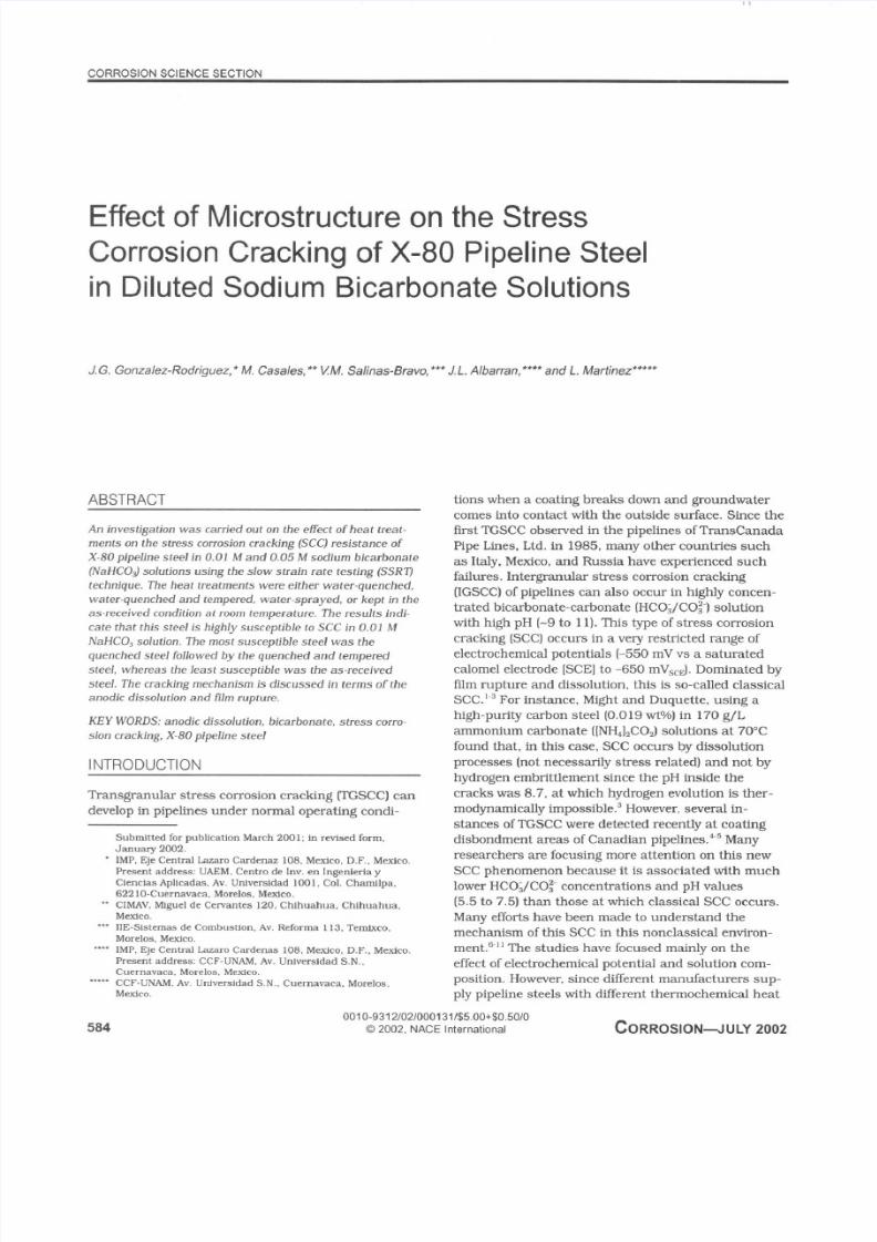
Effect of Microstructure on the StressCorrosion Cracking of X-80 Pipeline Steel
in Diluted Sodium Bicarbonate Solutions
J. G. Gonzalez-Rodriguez, * M. Casales, ** VM. Salinas-Bravo, *** J. L. Albarran, **** and L. Martinez’““’
ABSTRACT
TranSgmUlar stress corrosion cracking (TGSCC) can
develop in pipelines under normal ope rating condi-
t ions when a coating breaks down and groundwater
come s into contact wi th the outside surface. Since the
fi rst TGSC C observed in the pipelines ofTransCanada
Pipe Lines, Ltd. in 1985, many other cm mtr ies such
as Italy. Mexico, and Russia have exper ienced such
failures. Intergranular stres s corrosion crac king
(ICSCC) of pipel ines can also occur in highly concen-
trated bicarbonate-carbonate [HCO ;/COzl solution
with high pH I-9 to 11). This type of stress corrosion
cracking (SCCl occurs in a very restr icted range of
electrochemical potentials I-550 mV vs a saturated
calomel electrode [SCE] to -650 mV ,,J. Dominated by
film rupture and dissolution , this is so-called classica l
SCC.‘ .3 For instance. Might and Duquette, using a
high-purity carbon steel (0.019 wt%) in 170 g/L
amm onium carbonate I[NH,],C OJ solutions at 70°C
found that, in this case. SCC occurs by dissolution
processes (not necessar i ly stress related] and not by
hydrogen embri tt lement since the pH inside the
cracks w as 8.7, at which hydrogen evolution is ther-
modynam ical ly impossible.’ However, several in-
stances of TGSC C were detected recently at coating
disbandment areas of Canadian pipel ines.” Manyresearchers are focusing more attention on this new
SCC phenomenon because i t is associated with much
lower HCO ;/CO;- concentrations and pH values
(5.5 to 7.5) than those at which classical SCC occurs.
Many effor ts have been made to understand the
mechan ism of this SCC in this nonclassical envimn-
ment.6.” The studies have focused mainly on the
effect of electrochemical potential and solution com-
posi t ion. Howeve r. since di fferent manufacturers sup-
ply pipeline steels with di fferent thermoche mical heat
5840010-9312/021000131/$5.00+$0.50/0
f3 2002. NACE International CORROSION-IULY 2002
7/27/2019 Effect of Microstructure...
http://slidepdf.com/reader/full/effect-of-microstructure 2/7
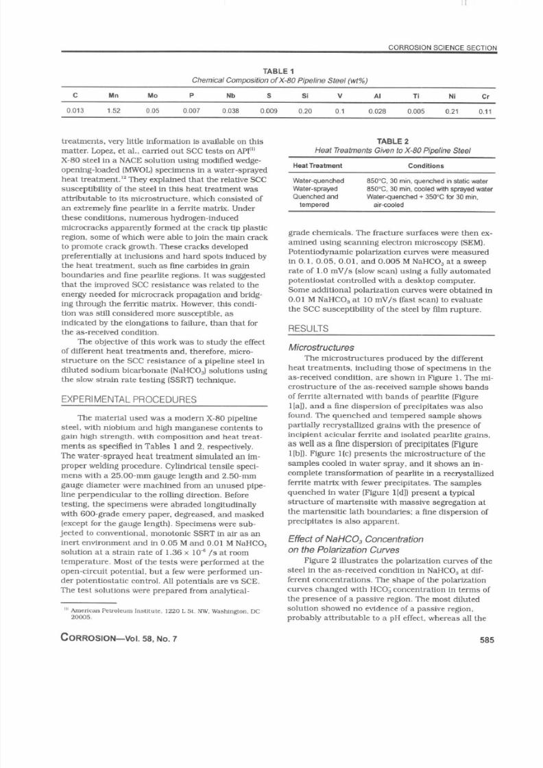
TABLE 1
Chemical Composit ion ofXt30 Pipel ine Steel (wt%)
c h ln MO P Nb s Si ” Al Ti Ni cr
treatmen ts, very l i t tle information is avai lable on this
matter . Lopez. et al ., carr ied out SCC tests on API” ’
X-80 steel in a NACE solution “sing modff ied wedge-
opening-loaded (MWOL ) specimens in a water-sprayed
heat treatment.” They explained that the relative S CC
susceptihl l l ty of the steel in this heat treatment was
attr ibutable to i ts microstructure, which consisted of
a” extremely f ine pear l ite in a ferr ite matr ix. Under
these condit ions. numerous hydrogen- induced
microcracks apparently formed at the crack t ip plastic
region, some of which were able to join the main crack
to promote crack gwvth. These cracks developed
preferential ly at inclusions and hard spots induced by
the heat treatment. such as fme carbides in grain
boundar ies and f ine pear l ite regions. It was suggested
that the improved SCC resistance was related to the
energy needed for microcrack propagation and br ldg-
ing through the ferr i tic matr ix. Howeve r, this condi-
t ion was sti l l considered more susceptible. as
indicated by the elongations to fai lure, than that for
the as-received condit ion.
TABLE 2
Heat Treafmenfs Given to X-80 Pipeline Sfeel
Heat Treatment
Water-quenched
Water-sprayed
Quenched and
tempered
Conditions
850°C. 30 min. quenched in static water
85O”C, 30 min. cooled with sprayed water
Water-quenched + 350°C fw 30 min.
air-cooled
grade chemicals. The fracture surfaces were then ex-
amined using scanning electron microscopy @EM ).
Potentiodynamic polar ization curves were measured
in 0.1, 0.05. 0.01. and 0.005 M NaHC O, at a sweeprate of 1.0 mV /s (slow scan1 using a ful ly au tomated
potentiostat controlled with a desktop computer.
Some addit ional polar ization cwve s were obtained in
0.01 M NaHCO, at 10 mV /s ( fast scan) to evaluate
the SCC susceptibi l i ty of the steel by f i lm rupture.
RESULTS
The objective of this work was to study the effect
of di fferent heat treatments and, therefore, micro-
structure on the SCC resistance of a pipeline steel in
di luted sodium bicarbonate INaHCO $ solutions using
the slow strain rate testing (SSR’IJ technique.
Microstructures
EXPERIMENTAL PROCEDURES
The mater ial used was a modern X-80 pipel ine
steel , wi th niobium and high manganese contents to
gain high strength, wi th cornposluon and heat treat-
men ts as speci f ied in Tables 1 and 2. respectively.
The water-sprayed heat treatment simulated a” im-
proper welding procedure. Cylindrical tensile speci-
mens with a 25.00.mm gauge length and 2.50-n,“ ,
gauge diameter were machined from an unused plpe-
line perpendicular to the roll ing direction. Before
testing, the specimens were abraded longi tudinal ly
with 600.grade emery paper, degreased. and masked
(except for the gauge length). Specimens were sub-
jected to conventional , monotonic SSRT in air as an
inert environment and in 0.05 M and 0.01 M NaHC O,
soluUon at a strain rate of 1.36 x lob /s at room
temperature. Mos t of the tests were performed at the
open-circuit potential , but a few were performed un-
der potentiostatic control . Al l potentials are vs SCE.
The test solutions were prepared from analyt ical-
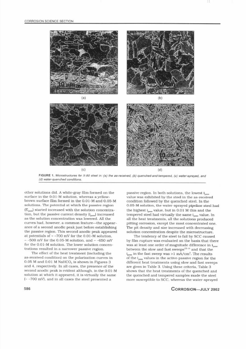
The microstructures produced by the di fferent
heat treatments, including those of specimens in the
as-received condit ion, are shown in Figure 1. The mi-
crostructure of the as-received sample shows bands
of ferrite alternated with bands of pearlite [Figure
l[al), and a fine dispersion of precipitate s was also
found. The quenched and tempered sample show s
partially recrystall ized grains with the presenc e of
i”cipient acicular ferrite and isolated pea rlite grains,
as well as a fine dispersionof precipitates Figurel Ibl1. Figure l (c) presents the microstructure of the
samples cooled in water spray, and i t shows a” in-
complete transfmma tion of pear l ite in a recrystall ized
ferr ite matr ix wi th fewer precipi tates. The samples
quenche d in wate r (Figure l[dll present a typical
structure of martensi te with massive segregation at
the martensi t ic lath boundar ies: a f ine dispersion of
precipi tates is also apparent.
Effect ofNaHC0, Concentration
on the Polarization Curves
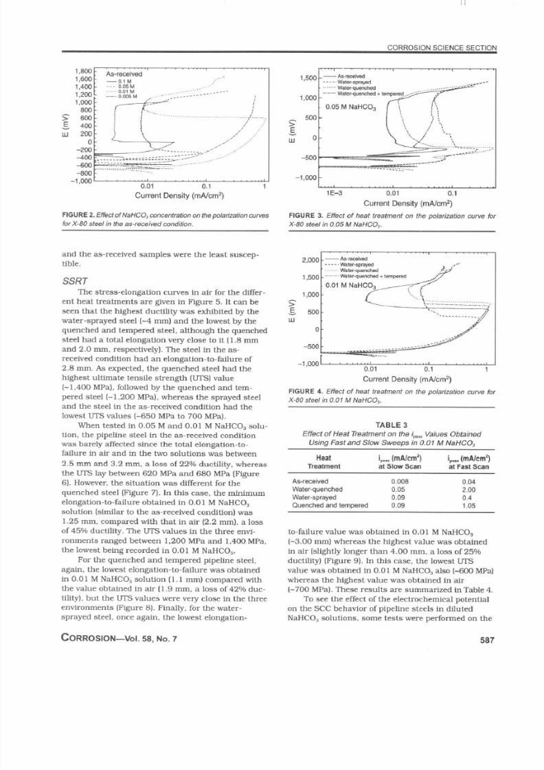
Figure 2 il lustrates the polarization curve s of the
steel in the as-received condit ion in NaHC O, at di f-
ferent concentrations. The shape of the polar ization
c”rves changed with HCO ; concentration in terms of
the presence of a passive region. The mos t d i luted
solution showed no evidence of a passive region.
probably attr ibutable to a pH effect, whereas al l the
CORROSION-VOI. 58, NO. 7 58 5
7/27/2019 Effect of Microstructure...
http://slidepdf.com/reader/full/effect-of-microstructure 3/7
(b)
Cd)
other solutions did. A white-gray ft im formed on the
surface in the 0.01-M solution, whereas a yel low-
brown surface f i lm formed in the 0.01-M and 0.05-M
solutions. The potential at which the passive region
(Ed started increased with the solution concen tra-
t ion, but the passive current densi ty I i& increased
as the solution concentration was lowered. Al l the
curves had, however, a ccmnnon featurethe appear-
ance of a second anodic peak just before establ ishing
the passive region. This second anodic peak appeared
at potentials of - -700 mV for the 0.01-M solution,- -500 mV for the 0.05-M solution, and - -650 mV
for the 0.01-M solution. The lower solution concen-
trations resulted in a narrower passive region.
The effect of the heat treatment ( including the
as-received condition) on the polarization curves in
0.05 M and 0.01 M NaHC O, is shown in Figures 3
and 4. respectively. In al l cases, the presence of the
second anodic peak is evident al though, in the 0.01-M
solution at which it appeared, it is virtually the sam e
(- -700 mV l. and in all case s the steel presented a
566
passive region. In both solutions, the lowest i , ,
value was exhibi ted by the steel in the as-received
condit ion fol lowed by the quenched steel . In the
0.05-M solution, the water-spraye d pipeline steel had
the highest $- , value. but in 0.01 M this and the
tempered steel had vir tual ly the same a.. value. In
al l the heat treatments, al l the solutions produced
pitt ing corrosion, except the most concentrated one.
The pi t densi ty and size increased with decreasing
solution concentration despi te the microstructure.
The tendency of the steel to fai l by SCC causedby f%m rupture was evaluated on the basis that there
was at least one order of magnitude di fference in i , ,
between the slow and fast sweep~‘~~‘~ and that the
iP.. in the fast sweep was >l mA/cn? The results
of the $=a values in the active-pa ssive region for the
di fferent heat treatments using slow and fast sweeps
are given in Table 3 . Using these criteria. Table 3
shows that the heat treatments of the quenched and
the quenched and tempered samples made the steel
more susceptible to SCC , whereas the water-sprayed
CORROSION-JULY 2002
7/27/2019 Effect of Microstructure...
http://slidepdf.com/reader/full/effect-of-microstructure 4/7
and the as-received samples were the least suscep-
tible.
SSRT
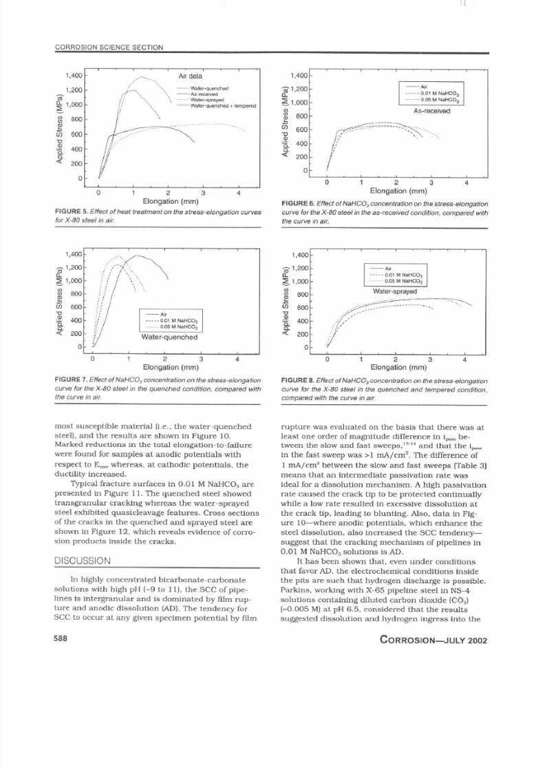
The stress-elong ation curve s in air for the differ-
ent heat treatments are given in Figure 5. I t can be
seen that the highest ducti l i ty was exhibi ted by the
water-sprayed steel ( -4 mm ) and the lowest by the
quenched and tempered steel , al though the quenched
steel had a total elongation very close to i t (1.8 mm
and 2.0 mm , respectively) . The steel in the as-
received condition had an elongation-to-failure of
2.8 mm . As expected, the quenched steel had the
highest ul t imate tensi le strength (UTS) value
(-1,400 MPa). fol lowed by the quenched and tem-
pered steel ( -1.200 MPa), whereas the sprayed steel
and the steel in the as-received condition had the
lowest UTS values (-650 MPa to 700 MPa).
When tested in 0.05 M and 0.01 M NaHC O, solu-
tion, the pipeline steel in the as-received condition
was barely affected since the total elongation-to-
fai lure in air and in the two solutions was between
2.5 mm and 3.2 mm , a loss of 22% ducti l i ty. whereas
the LIT3 lay between 620 MPa and 680 MPa [Figure
6). Howeve r, the si tuation was di fferent for the
quenched steel (Figure 7). In this case, the minimum
elongation-to-fai lure obtained in 0.01 M NaHC O,
solution Isiml lar to the as-received condit ion) was
1.25 mm . compared with that in air (2.2 mm ), a lossof 45% ducti l i ty. The UTS values in the three envi-
ronments ranged be tween 1.200 MPa and 1,400 MPa,
the lowest being recorded in 0.01 M NaH CO,.
For the quenched and tempered pipeline steel .
again. the lowe st elongation-to-failure was obtained
in 0.01 M NaHC O, solution (1.1 mm ) compared with
the value obtained in air (1.9 mm , a loss of 42% duc-
t i l ity) , but the UTS values were very close in the three
environments [Figure 8). Final ly. for the water-
sprayed steel . once again, the lowest elongation-
CORROSION-VOI. 8,NO.7
1E-3 0.01 0.1
Current Density (mAfcm2)
FIGURE 3. Effect of heat treatment on the polarization cuwe for
X-80 steel in 0.05 M NaHCO,.
sr 5ouw
0
-500
-I,0001 ““’0.01 0.1 1
Current Density (mAJcm2)
FIGURE 4. Effect of heat treatment on the polarization curye forX-80 steel in 0.01 M NaHCO,.
TABLE 3
Effect o f Heat Treatment on the tw,. Values Obtained
Using Fast and Slow Sweeps in 0.01 M NaHCO,
Heat ivy (mAtem’) iv (mAtem’)
TW*tme”t at stow Scan at Fast Scan
As-received 0.008 0.04
Waterquenched 0.05 2.00Water-sprayed 0.09 0.4
Quenched and tempered 0.09 1.05
to- failure value was obtained in 0.01 M NaHC O,
(-3.00 mm ) whereas the highest value was obtained
in air Is l ightly longer than 4.00 m m, a loss of 25%
ducti l i ty) (Figure 9). In this case. the lowest UTS
value was obtained in 0.01 M NaHC O, also (-600 MP a)
whereas the highest value was obtained in air
I-700 MPal. These resul ts are summ arized inTable 4.
To see the effect of the electrochemical potential
on the SC C behavior of pipeline stee ls in diluted
NaHC O, solutions, some tests were performed on the
7/27/2019 Effect of Microstructure...
http://slidepdf.com/reader/full/effect-of-microstructure 5/7
1.4wJ ,_. .... . . .._. Air data 1
Water-quenched
mos t susceptible mater ial ( i .e.. the water-quenched
steel) . and the resul ts are shown in Figure IO.
Marke d reductions in the total elongation-to-failure
were found for samples at anodic potentials wi th
respect to E, whereas. at cathodic potentials, the
ducti l i ty increased.
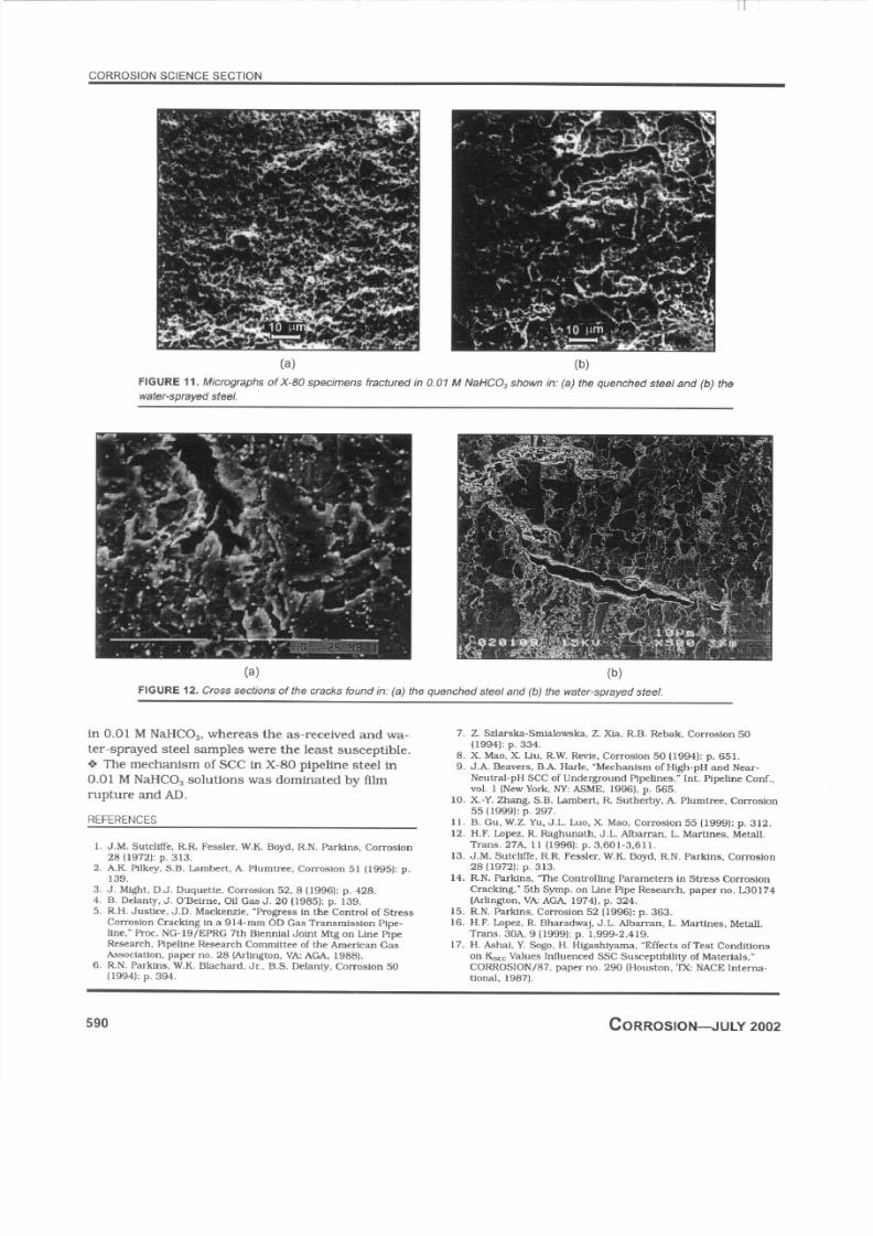
Apical fracture surfaces in 0.01 M NaHC O, are
presented in Figure 11. The quenched steel showed
transgranular cracking whereas the water-sprayed
steel exhibi ted quasicleavage features. Cross sections
of the cracks in the quenched and sprayed steel areshown in Figure 12. which reveals evidence of corro-
sion products inside the cracks.
DISCUSSION
In highly concentrated bicarbonate-carbonate
solutions with high pH l-9 to 11). the SCC of plpe-
lines is intergranular and is domina ted by tl lm rup-
ture and anodic dissolution (AD). ‘The tendency for
SCC to occur at any given specimen potential by f i lm
1,400 -
Pzoo.
~i,OOO-
As-received
0 ’
0 1 2 3 4
Elongat ion (mm)
0
0 1 2 3 4
Elongat ion (mm)
rupture was evaluated on the basis that there was at
least one order of magn itude difference in i-. be-
tween the slow and fast s~eeps,‘~~” and that the &
in the fast sweep was >l mA/cn? . The di fference of
1 mA/cm = between the slow and fast sweeps (Table 3)
means that an intermediate passivation rate was
ideal for a dissolution mecha nism. A high passivation
rate caused the crack t ip to be protected continual ly
whi le a low rate resul ted in excessive dissolution at
the crac k tip. leading to blunting. Also, data in fig-
ure IO-where anodic potentials, which enhance thesteel dissolution, also increased the SCC tendency-
suggest that the cracking mechan ism of pipel ines In
0.01 M NaHC O, solutions is AD.
It has been shown that, even under condit ions
that favor AD. the electrochemical condit ions inside
the pi ts are such that hydrogen discharge is possible.
Parkins . working with X-65 pipeline steel in NS-4
solutions containing diluted carbon dioxide (COJ
l=O.O05 M ) at pH 6.5, considered that the resul ts
suggested dissolution and hydrogen ingress into the
7/27/2019 Effect of Microstructure...
http://slidepdf.com/reader/full/effect-of-microstructure 6/7
steel .” Simi lar resul ts were found by Gu, et al ., for
X-80.type steel in the same solution.” However, in
the NS-4 solutions, the X-80 steel did not show any
passive region” whereas, in the present study, i t did
Figure 4). regardless of the microstructure. demon-
strating the importance of the f i lm rupture. Another
di fference is that. in the NS-4 solution. the SCC sus-ceptibil ity increased as the applied poten tial was
more cathodic, unl ike the present case. in which
cathodic potentials decreased the SCC susceptibi l i ty.
These resul ts confhm those of Parki”s.15 that see of
carbon steels in carbonate solutions occurred by the
dissolution process of metal at the crack t ips. The
presence of corrosion products inside the cracks sup-
ports this idea. The dissolution rates at the crack
tips were high enough to cause the crack wal ls to
passivate. providing a large cathode inside the crack,
coupled to a smal l anode at the crack t ip where f i lm
rupture took place. The role of the applied potential
was to maintain the al loy surface in the potential
range where rapid rupture of the pass ive fi lm led to a
mzdm um dissolution rate at the crack t ip, whi le at
the same time fudng the potential of the crack wal ls
in the passive regime.
The quenched steel was mos t susceptible to SCC
because the martensi te was a highly stressed micro-
structure as a resul t of excess carbon trapped inter-
~ti tial1y.l~ Hence, i t is assumed that grain boundruy
carbon segregation coupled with severe internal
stresses renders grain boundar ies susceptible to
stress corrosion crack propagation. So i t is expected
that, under these conditions. the crack propagation
is mainly intergranular. In this work, the authors
were not able to detect intergranular cracking. as evi-
dented by Figures 11 and 12. Howeve r, as mentioned
in the Introduction, in the nonclassical SCC found in
lower concentrations of carbonate/bicarbonate solu-
t ions. the SCC propagation was transgranular, as
opposed to the IGSCC found in highly concentrated
carbonate/bicarbonate solutions. In the quenched
condit ion, i t is expected that carbon segregation at
grain and interlath boundaries comb ined with an in-
ternally stressed marte nsite will give rise to an in-
creasingly susceptible steel condit ion.
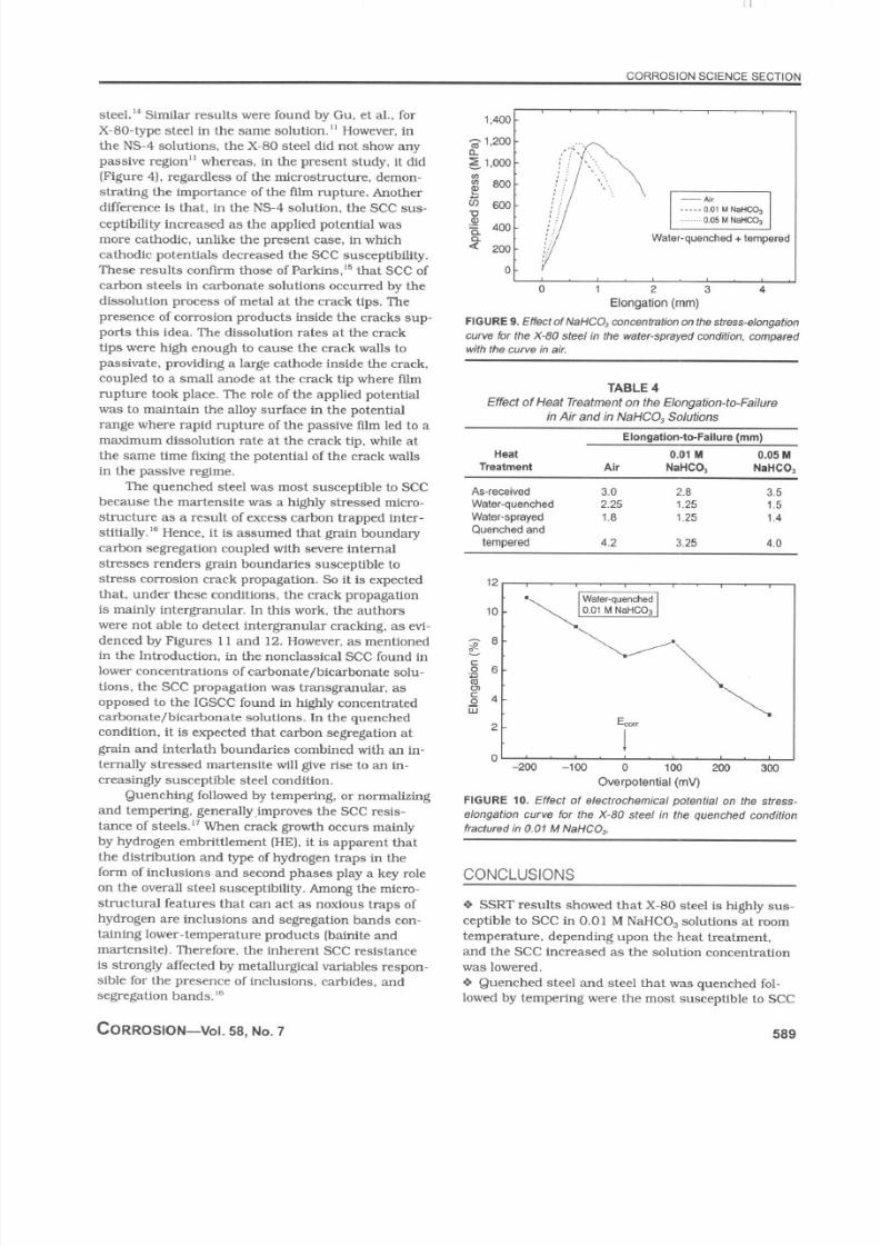
Quenching followed by temp ering, or normalizing
and temper ing, general lyjmproves the SCC resis-
tance of steels.” When crack growth occurs mainly
by hydrogen embri tt lement (HE). i t is apparent thatthe distribution and type of hydrogen traps in the
form o f inclusions and second phases play a key role
on the overal l steel susceptibi l i ty. Among the micro-
structural features that can act as noxious traps of
hydrogen are i”clusions and segregation bands con-
taining lower-tempe rature produ cts (bainite and
martensi te) . Therefore, the inherent SCC resistance
is strongly affected by metal lurgical var iables respon-
sible for the presence of inclusions, carbides, and
segregation bands.”
CORROSION-W. 58, NO. 7
1,400t
TABLE 4
Effect of Heat Treatment on the Elongation-to-Failure
in Air and in NaHCO. Solut ionsElongation-to-Failure (mm)
Heat 0.01 M 0.05 M
Treatment Air NaHCO, NaHCO,
I0
-200 -?@I 0 100 200 300
Overpotential (mV)
CONCLUSIONS
9 SSRT resul ts showed that X-80 steel is highly sus-
ceptible to SCC in 0.01 M NaHC O, solutions at room
temperature. depending upon the heat treatment.
and the SCC increased as the solution concentration
was lowered.
0 Quenched steel and steel that was quenched fol-
lowed by temper ing were the mos t susceptible to SCC
58 9
7/27/2019 Effect of Microstructure...
http://slidepdf.com/reader/full/effect-of-microstructure 7/7
CORROSION SCIENCE SECTION
(a) (b)
FIGURE 11. Micrographs ofX-80 specimens fractured in 0.01 M NaHC O, shown in: (a) Ihe quenched sfeel and (b) the
water-sprayed steel .
in 0.01 M NaHC O,, whereas the as-received and wa-
ter-sprayed steel samples were the least susceptible.
0 Tbe mechan ism of SCC in X-80 pipel ine steel in
0.01 M NaHC O, solutions was dominated by f i lm
rupture and AD.
REFERENCES
(b)
quenched steel and (b, the waler-sprayed steel
CORROSION-JULY 2002