Embed Size (px)
Citation preview
EFFECT OF DRY MACHINING ON TOOL WEAR
MADIHAH BINTI ZUBIR
This thesis is submitted as a partial fulfillment of the requirements for the award of the
bachelor of mechanical engineering with manufacturing engineering
Faculty of Mechanical Engineering
UNIVERSITI MALAYSIA PAHANG
JUNE, 2012

v
ABSTRACT
This thesis presents the wear of coated carbide insert in machining carbon steel AISI
1065. Machineability of AISI 1065 is considered good with high strength, high
resistance to breakage and high modulus of elasticity. This has increased the tool wear
of the coated carbide when it is used to machining of AISI 1065. The main objective of
this project is to examine the progress of tool wear, identify the interaction between the
different parameters and to find out the optimal parameter that can be used in dry
machining. In this project, 33 full factorial design of experiments (DOE) was employed
in STATISTICA software to plan and perform the experiment systematically so that any
possible experimental error would be minimized. Machining variables considered are
cutting length, cutting speed and feed rate. The variables for there levels were 90, 120
and 150 rev/min for cutting speed, 0.13, 0.18, 0.22 mm/rev for the feed rate and 0.8,
1.0, and 1.2 mm for depth of cut respectively. Machining AISI 1065 was carried out by
using the conventional lathe machine. The work piece is been turning for 7 rounds for
each turning process. After 7 rounds of turning process, wear of the coated carbide
insert was investigated and measured by using Microscope MarVision MM320 and
Quadra check 300. Experimental data was analyzed in STATISTICA. Analysis of
variance (ANOVA) is done to identify the most influencing parameters in this research.
From the ANOVA analysis, the cutting speed and the feed rate are the most significant
parameter that influencing tool wear. Depth of cut effect can be negligible. The
minimum tool wears is at the lowest cutting speed that is 90rev/min and at lowest feed
rate 0.13mm/rev.

vi
ABSTRAK
Tesis ini menyajikan kehausan mata alat pemotong diselaputi karbide dalam
memesinkan besi karbon AISI 1065. Kebolehmesinan besi AISI 1065 dimesinkan
adalah dengan kekuatan yang tinggi, keupayaan menahan dari patah, dan nilai modulus
kekenyalan yang tinggi . Ini menyebabkan alat pemotong diselaputi karbide akan cepat
haus. Objektif utama projek ini ialah untuk mengkaji kemajuan kehausan alat mata,
mengenalpasti interaksi antara parameter yang berlainan dan untuk mengetahui
parameter yang optimum yang boleh digunakan dalam pemesinan kering. Dalam projek
ini, rekaan eksperimen pemfaktoran penuh 33 dijanakan dalam perisian STATISTICA
untuk mengatur dan menjalankan eksperimen ini secara sistematik untuk mengurangkan
apa-apa ralat eksperimen yang mungkin berlaku. Parameter yang dipertimbangkan ialah
kelajuan pemotongan, kadar kelajuan pemotongan dan kedalaman pemotongan. Tiga
tahap parameter yang digunakan ialah 90, 120 dan 150 rev/min untuk kelajuan
pemotongan, 0.13, 0.18 dan 0.22 mm/rev untuk kadar kelajuan bahan dipotong dan 0.8,
1.0 dan 1.2 untuk kedalaman pemotongan. Proses memesinkan besi AISI 1065
dijalankan dengan menggunakan mesin larik konvensional. Bahan kajian dilarikkan
untuk 7 pusingan untuk setiap proses larikan. Selepas 7 proses larikan, kehausan alat
pemotong disepaluti karbide dikaji dan diukur menggunakan mikroskop MarVision
MM320 dan Quadra Chek 300. Data eksperimen dianalisis menggunakan
STATISTICA. Analisis varians (ANOVA) dilakukan untuk mengenalpasti parameter
yang paling mempengaruhi kehausan alat pemotong. Daripada analisis ANOVA,
kelajuan pemotongan dan kadar kelajuan pemotongan adalah parameter yang paling
penting yang mempengaruhi kehausan alat pemotong. Kesan kedalaman pemotongan
boleh diabaikan. Kehausan mata pemotong paling minimum adalah pada kelajuan
pemotongan 90rev/min dan kadar kelajuan pemotongan 0.13mm/rev.

vii
TABLE OF CONTENTS
Page
SUPERVISOR’S DECLARATION ii
STUDENTS’S DECLARATION iii
ACKNOWLEDGEMENTS iv
ABSTRACT v
ABSTRAK vi
TABLE OF CONTENTS vii
LIST OF TABLES x
LIST OF FIGURES xi
LIST OF SYMBOLS xiii
LIST OF ABBREVIATIONS xiv
CHAPTER 1 INTRODUCTION
1.1 Project Background 1
1.2 Problem Statement 2
1.2.1 Problem 2
1.2.2 Solution of the problem 2
1.3 Project Objectives 3
1.4 Scope of project 3
CHAPTER 2 LITERATURE REVIEW
2.1 Introduction 4
2.2 Plain Carbon Steel 4
2.3 Heat Treatment 6
2.3.1 Introduction 6
2.3.2 Heat Treatment Process 8
2.3.3 Quenching Process 9
2.4 Vickers Hardness Test 10
2.5 Dry Machining 12

viii
2.6 Lathe Machine 14
2.6.1 Turning high carbon steel 16
2.7 Coated Carbide Insert 16
2.8 Tool Wear 17
2.9 Design of Experiment (DOE) 22
2.10 Analysis of variance (ANOVA) 24
2.11 Summary 24
CHAPTER 3 METHODOLOGY
3.1 Introduction 26
3.2 Flow Chart 28
3.3 Preparation of work piece 29
3.3.1 Material selection 30
3.4 Heat Treatment 31
3.4.1 Quenching process 32
3.5 Hardness Test 32
3.6 Selection of parameters 34
3.7 Turning Operation 38
3.8 Data Recording 40
3.9 Data Analysis 41
CHAPTER 4 RESULTS AND DISCUSSION
4.1 Introduction 46
4.2 Hardness Test 46
4.2.1 Experimental Result 46
4.2.2 Discussion 48
4.3 Impact of cutting parameters to the coated carbide insert 49
4.4 Statistical Analysis: Analysis of variance (ANOVA) 51
4.5 Discussion 58
ix
CHAPTER 5 CONCLUSION AND RECOMMENDATIONS
5.1 Introduction 60
5.2 Conclusion 60
5.3 Recommendation 61
REFERENCES 62
APPENDICES 64

x
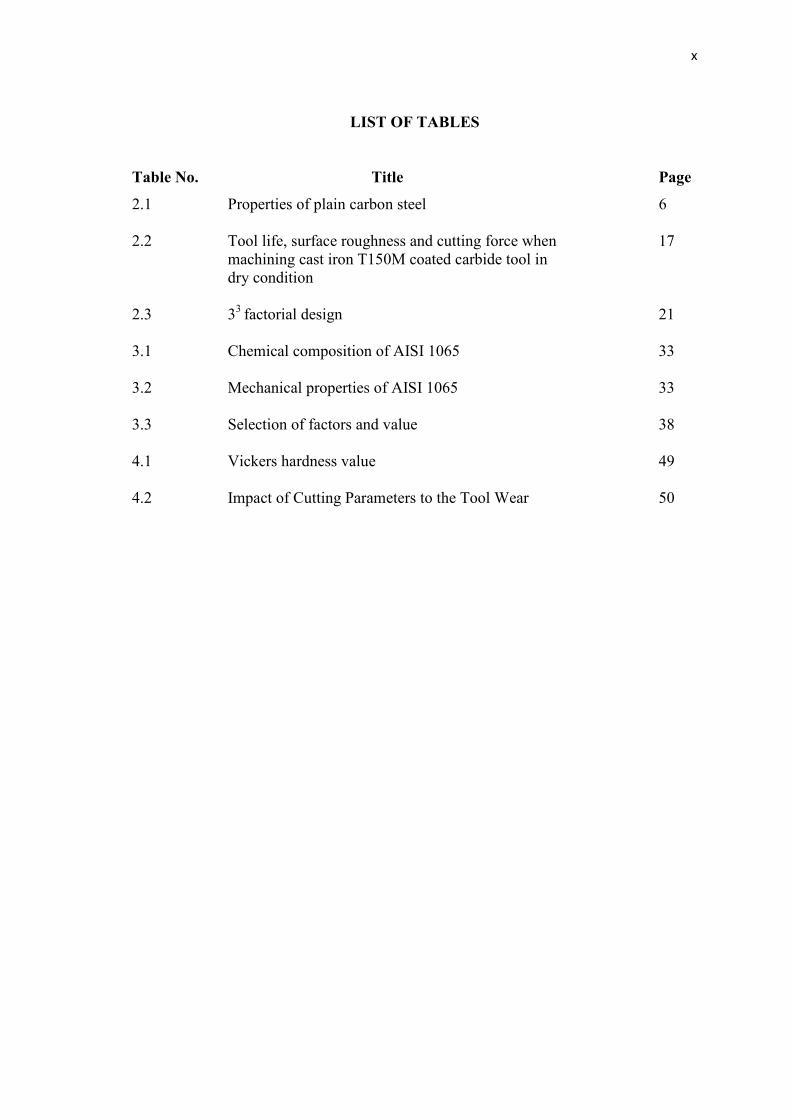
LIST OF TABLES
Table No. Title Page
2.1 Properties of plain carbon steel 6
2.2 Tool life, surface roughness and cutting force when 17
machining cast iron T150M coated carbide tool in
dry condition
2.3 33
factorial design 21
3.1 Chemical composition of AISI 1065 33
3.2 Mechanical properties of AISI 1065 33
3.3 Selection of factors and value 38
4.1 Vickers hardness value 49
4.2 Impact of Cutting Parameters to the Tool Wear 50

xi
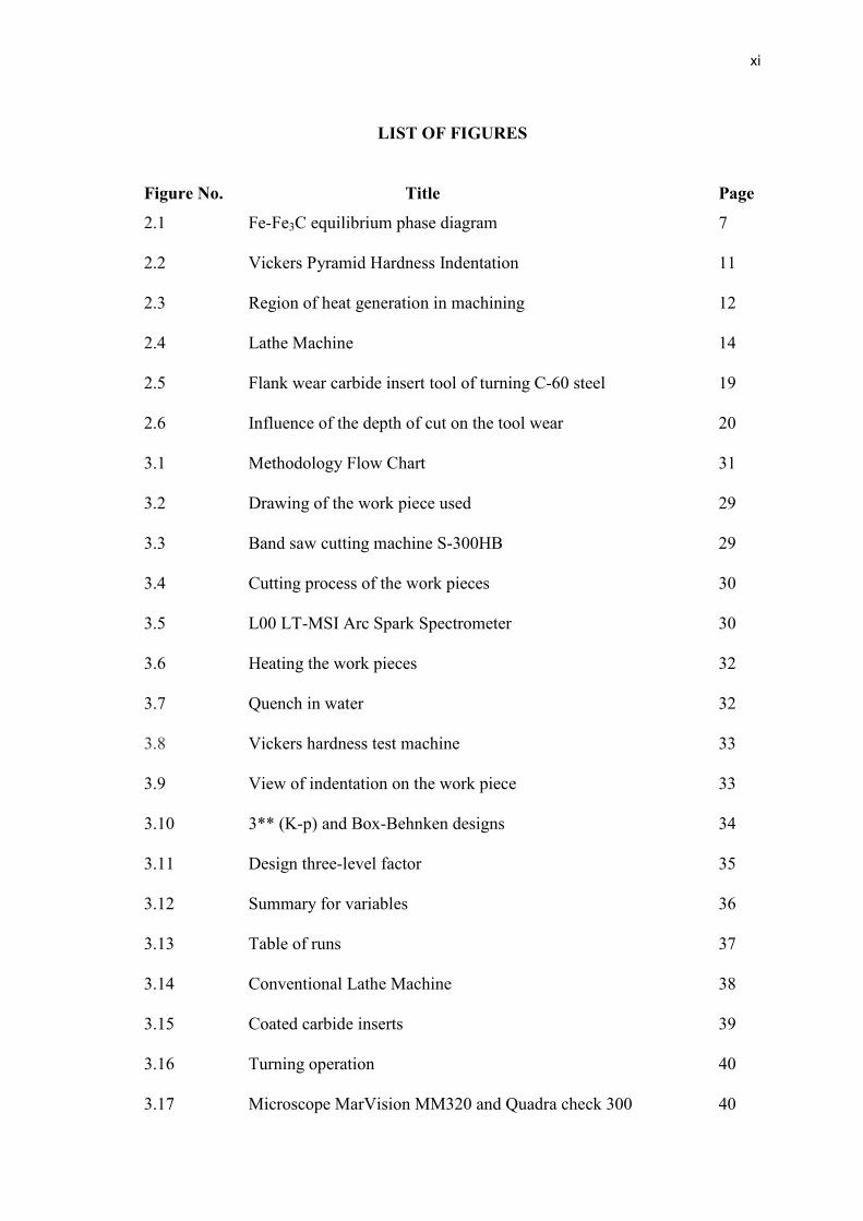
LIST OF FIGURES
Figure No. Title Page
2.1 Fe-Fe3C equilibrium phase diagram 7
2.2 Vickers Pyramid Hardness Indentation 11
2.3 Region of heat generation in machining 12
2.4 Lathe Machine 14
2.5 Flank wear carbide insert tool of turning C-60 steel 19
2.6 Influence of the depth of cut on the tool wear 20
3.1 Methodology Flow Chart 31
3.2 Drawing of the work piece used 29
3.3 Band saw cutting machine S-300HB 29
3.4 Cutting process of the work pieces 30
3.5 L00 LT-MSI Arc Spark Spectrometer 30
3.6 Heating the work pieces 32
3.7 Quench in water 32
3.8 Vickers hardness test machine 33
3.9 View of indentation on the work piece 33
3.10 3** (K-p) and Box-Behnken designs 34
3.11 Design three-level factor 35
3.12 Summary for variables 36
3.13 Table of runs 37
3.14 Conventional Lathe Machine 38
3.15 Coated carbide inserts 39
3.16 Turning operation 40
3.17 Microscope MarVision MM320 and Quadra check 300 40

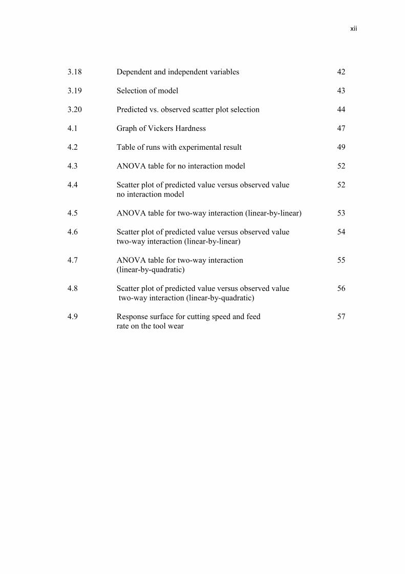
xii
3.18 Dependent and independent variables 42
3.19 Selection of model 43
3.20 Predicted vs. observed scatter plot selection 44
4.1 Graph of Vickers Hardness 47
4.2 Table of runs with experimental result 49
4.3 ANOVA table for no interaction model 52
4.4 Scatter plot of predicted value versus observed value 52
no interaction model
4.5 ANOVA table for two-way interaction (linear-by-linear) 53
4.6 Scatter plot of predicted value versus observed value 54
two-way interaction (linear-by-linear)
4.7 ANOVA table for two-way interaction 55
(linear-by-quadratic)
4.8 Scatter plot of predicted value versus observed value 56
two-way interaction (linear-by-quadratic)
4.9 Response surface for cutting speed and feed 57
rate on the tool wear

xiii
LIST OF SYMBOLS
°C Degree Celsius
γ Gamma
R2
Coefficient of determination

xiv
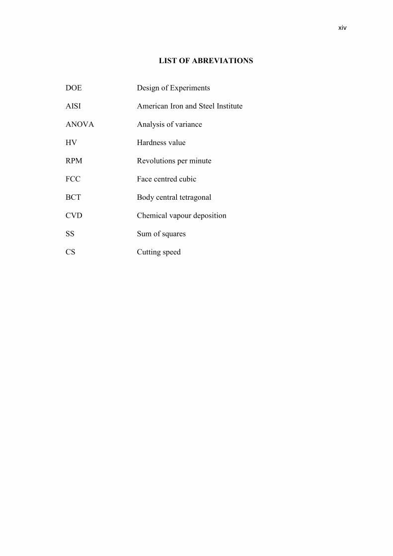
LIST OF ABREVIATIONS
DOE Design of Experiments
AISI American Iron and Steel Institute
ANOVA Analysis of variance
HV Hardness value
RPM Revolutions per minute
FCC Face centred cubic
BCT Body central tetragonal
CVD Chemical vapour deposition
SS Sum of squares
CS Cutting speed
IN THE NAME OF ALLAH,
THE MOST BENEFICENT, THE MOST MERCIFUL
A special dedication of This Grateful Feeling to My..
Beloved parents, En.Zubir bin Daud and Pn. Laila binti Mohd Zain for giving me full of
moral and financial support. It is very meaningful to me in order to finish up my
degree’s study. Not forgetting also to all my loving siblings, and also to my beloved one.
Last but not least to all my colleagues and my lovely friends.
Thanks for all the support, wishes and love.
ACKNOWLEDGEMENT
I would like to thank Allah Almighty for blessing and giving me strength to
accomplish this thesis. I would like to acknowledge and extend my heartfelt gratitude to
my supervisor Mr. Lee Giok Chui SMP., KMN, lecturer of Faculty of Mechanical
Engineering for his continues support, helpful advice and valuable guidance throughout
my thesis. This thesis could not have been done without Mr. Lee Giok Chui SMP.,
KMN, who not only served as my supervisor but also encouraged and guide me through
the writing up thesis process by giving the best effort. I would also like to thank him for
helping me to complete this project.
I would like to express my appreciation to the lab instructor and the staffs of
Faculty of Mechanical Engineering Universiti Malaysia Pahang for their teach and
guidance during the period of the project. I also wish to express sincere appreciation to
all my friends for their advices and their helps to do the study and complete this project.
Most importantly, I would like to thank to my family who always sacrifices their
time and continuous support me to achieve my dreams and goals. I would like to thank
them for all their supports and encouragements for me.
v
ABSTRACT
This thesis presents the wear of coated carbide insert in machining carbon steel AISI
1065. Machineability of AISI 1065 is considered good with high strength, high
resistance to breakage and high modulus of elasticity. This has increased the tool wear
of the coated carbide when it is used to machining of AISI 1065. The main objective of
this project is to examine the progress of tool wear, identify the interaction between the
different parameters and to find out the optimal parameter that can be used in dry
machining. In this project, 33 full factorial design of experiments (DOE) was employed
in STATISTICA software to plan and perform the experiment systematically so that any
possible experimental error would be minimized. Machining variables considered are
cutting length, cutting speed and feed rate. The variables for there levels were 90, 120
and 150 rev/min for cutting speed, 0.13, 0.18, 0.22 mm/rev for the feed rate and 0.8,
1.0, and 1.2 mm for depth of cut respectively. Machining AISI 1065 was carried out by
using the conventional lathe machine. The work piece is been turning for 7 rounds for
each turning process. After 7 rounds of turning process, wear of the coated carbide
insert was investigated and measured by using Microscope MarVision MM320 and
Quadra check 300. Experimental data was analyzed in STATISTICA. Analysis of
variance (ANOVA) is done to identify the most influencing parameters in this research.
From the ANOVA analysis, the cutting speed and the feed rate are the most significant
parameter that influencing tool wear. Depth of cut effect can be negligible. The
minimum tool wears is at the lowest cutting speed that is 90rev/min and at lowest feed
rate 0.13mm/rev.
vi
ABSTRAK
Tesis ini menyajikan kehausan mata alat pemotong diselaputi karbide dalam
memesinkan besi karbon AISI 1065. Kebolehmesinan besi AISI 1065 dimesinkan
adalah dengan kekuatan yang tinggi, keupayaan menahan dari patah, dan nilai modulus
kekenyalan yang tinggi . Ini menyebabkan alat pemotong diselaputi karbide akan cepat
haus. Objektif utama projek ini ialah untuk mengkaji kemajuan kehausan alat mata,
mengenalpasti interaksi antara parameter yang berlainan dan untuk mengetahui
parameter yang optimum yang boleh digunakan dalam pemesinan kering. Dalam projek
ini, rekaan eksperimen pemfaktoran penuh 33 dijanakan dalam perisian STATISTICA
untuk mengatur dan menjalankan eksperimen ini secara sistematik untuk mengurangkan
apa-apa ralat eksperimen yang mungkin berlaku. Parameter yang dipertimbangkan ialah
kelajuan pemotongan, kadar kelajuan pemotongan dan kedalaman pemotongan. Tiga
tahap parameter yang digunakan ialah 90, 120 dan 150 rev/min untuk kelajuan
pemotongan, 0.13, 0.18 dan 0.22 mm/rev untuk kadar kelajuan bahan dipotong dan 0.8,
1.0 dan 1.2 untuk kedalaman pemotongan. Proses memesinkan besi AISI 1065
dijalankan dengan menggunakan mesin larik konvensional. Bahan kajian dilarikkan
untuk 7 pusingan untuk setiap proses larikan. Selepas 7 proses larikan, kehausan alat
pemotong disepaluti karbide dikaji dan diukur menggunakan mikroskop MarVision
MM320 dan Quadra Chek 300. Data eksperimen dianalisis menggunakan
STATISTICA. Analisis varians (ANOVA) dilakukan untuk mengenalpasti parameter
yang paling mempengaruhi kehausan alat pemotong. Daripada analisis ANOVA,
kelajuan pemotongan dan kadar kelajuan pemotongan adalah parameter yang paling
penting yang mempengaruhi kehausan alat pemotong. Kesan kedalaman pemotongan
boleh diabaikan. Kehausan mata pemotong paling minimum adalah pada kelajuan
pemotongan 90rev/min dan kadar kelajuan pemotongan 0.13mm/rev.
vii
TABLE OF CONTENTS
Page
SUPERVISOR’S DECLARATION ii
STUDENTS’S DECLARATION iii
ACKNOWLEDGEMENTS iv
ABSTRACT v
ABSTRAK vi
TABLE OF CONTENTS vii
LIST OF TABLES x
LIST OF FIGURES xi
LIST OF SYMBOLS xiii
LIST OF ABBREVIATIONS xiv
CHAPTER 1 INTRODUCTION
1.1 Project Background 1
1.2 Problem Statement 2
1.2.1 Problem 2
1.2.2 Solution of the problem 2
1.3 Project Objectives 3
1.4 Scope of project 3
CHAPTER 2 LITERATURE REVIEW
2.1 Introduction 4
2.2 Plain Carbon Steel 4
2.3 Heat Treatment 6
2.3.1 Introduction 6
2.3.2 Heat Treatment Process 8
2.3.3 Quenching Process 9
2.4 Vickers Hardness Test 10
2.5 Dry Machining 12
viii
2.6 Lathe Machine 14
2.6.1 Turning high carbon steel 16
2.7 Coated Carbide Insert 16
2.8 Tool Wear 17
2.9 Design of Experiment (DOE) 22
2.10 Analysis of variance (ANOVA) 24
2.11 Summary 24
CHAPTER 3 METHODOLOGY
3.1 Introduction 26
3.2 Flow Chart 28
3.3 Preparation of work piece 29
3.3.1 Material selection 30
3.4 Heat Treatment 31
3.4.1 Quenching process 32
3.5 Hardness Test 32
3.6 Selection of parameters 34
3.7 Turning Operation 38
3.8 Data Recording 40
3.9 Data Analysis 41
CHAPTER 4 RESULTS AND DISCUSSION
4.1 Introduction 46
4.2 Hardness Test 46
4.2.1 Experimental Result 46
4.2.2 Discussion 48
4.3 Impact of cutting parameters to the coated carbide insert 49
4.4 Statistical Analysis: Analysis of variance (ANOVA) 51
4.5 Discussion 58

ix
CHAPTER 5 CONCLUSION AND RECOMMENDATIONS
5.1 Introduction 60
5.2 Conclusion 60
5.3 Recommendation 61
REFERENCES 62
APPENDICES 64
x
LIST OF TABLES
Table No. Title Page
2.1 Properties of plain carbon steel 6
2.2 Tool life, surface roughness and cutting force when 17
machining cast iron T150M coated carbide tool in
dry condition
2.3 33
factorial design 21
3.1 Chemical composition of AISI 1065 33
3.2 Mechanical properties of AISI 1065 33
3.3 Selection of factors and value 38
4.1 Vickers hardness value 49
4.2 Impact of Cutting Parameters to the Tool Wear 50
xi
LIST OF FIGURES
Figure No. Title Page
2.1 Fe-Fe3C equilibrium phase diagram 7
2.2 Vickers Pyramid Hardness Indentation 11
2.3 Region of heat generation in machining 12
2.4 Lathe Machine 14
2.5 Flank wear carbide insert tool of turning C-60 steel 19
2.6 Influence of the depth of cut on the tool wear 20
3.1 Methodology Flow Chart 31
3.2 Drawing of the work piece used 29
3.3 Band saw cutting machine S-300HB 29
3.4 Cutting process of the work pieces 30
3.5 L00 LT-MSI Arc Spark Spectrometer 30
3.6 Heating the work pieces 32
3.7 Quench in water 32
3.8 Vickers hardness test machine 33
3.9 View of indentation on the work piece 33
3.10 3** (K-p) and Box-Behnken designs 34
3.11 Design three-level factor 35
3.12 Summary for variables 36
3.13 Table of runs 37
3.14 Conventional Lathe Machine 38
3.15 Coated carbide inserts 39
3.16 Turning operation 40
3.17 Microscope MarVision MM320 and Quadra check 300 40
xii
3.18 Dependent and independent variables 42
3.19 Selection of model 43
3.20 Predicted vs. observed scatter plot selection 44
4.1 Graph of Vickers Hardness 47
4.2 Table of runs with experimental result 49
4.3 ANOVA table for no interaction model 52
4.4 Scatter plot of predicted value versus observed value 52
no interaction model
4.5 ANOVA table for two-way interaction (linear-by-linear) 53
4.6 Scatter plot of predicted value versus observed value 54
two-way interaction (linear-by-linear)
4.7 ANOVA table for two-way interaction 55
(linear-by-quadratic)
4.8 Scatter plot of predicted value versus observed value 56
two-way interaction (linear-by-quadratic)
4.9 Response surface for cutting speed and feed 57
rate on the tool wear

xiii
LIST OF SYMBOLS
°C Degree Celsius
γ Gamma
R2
Coefficient of determination
xiv
LIST OF ABREVIATIONS
DOE Design of Experiments
AISI American Iron and Steel Institute
ANOVA Analysis of variance
HV Hardness value
RPM Revolutions per minute
FCC Face centred cubic
BCT Body central tetragonal
CVD Chemical vapour deposition
SS Sum of squares
CS Cutting speed
CHAPTER 1
INTRODUCTION
1.1 PROJECT BACKGROUND
During machining process, friction between work piece and grain cause high
temperature on cutting tool. The effect of this generated heat that will sooner decrease
the tool life, increase surface roughness and decrease the dimensional sensitivities of
work material. This case is more important when machining of difficult-to-cut
materials, when more heat would be observed.
The application of cutting fluid or coolant is an alternative that has been used
widespread in all machining process. Cutting fluid is used to reduce friction and wear
(improving tool life and surface finish), to reduce cutting force and energy
consumption, to cool the cutting zone, to wash away chips and to protect machined
surfaces from environmental corrosion.
However, because of their damaging influences on the environment, their
applications have been limited in machining process. Cutting fluid can be expensive
and seriously degrade quality of environment. Consequently, many governments
recommend the manufacturers to reduce the volume and the toxicity of their cutting
fluids. It is potentially cause health problem to the operator. Besides, cutting fluids
requires proper recycling and disposal, thus adding to the cost of the machining
operation.
For these reasons dry machining has become an increasingly important
approach. In dry machining, no coolant or lubricant is used. The implementation of dry
machining will bring down the manufacturing cost.