Embed Size (px)
Citation preview

Page 466
Effect of Cutting Fluids on H.S.S and Carbide Cutting Tools by
Thermal Analysis
Chowdary Manjusha
M.Tech (Thermal Engineering)
Kakinada Institute of Technology
and Science,
Divili, Peddapuram, A.P, India.
K.Srilakshmi, M.Tech
Assistant Professor
Kakinada Institute of Technology
and Science,
Divili, Peddapuram, A.P, India.
Prof.S.Rajasekhar, M.Tech (Ph.D)
Associate Professor & HoD,
Kakinada Institute of Technology
and Science,
Divili, Peddapuram, A.P, India.
ABSTRACT
Any liquid or gas applied directly to machining
operation to improve cutting performance
Two main problems addressed by cutting fluids: Heat
generation at shear zone and friction zone, Friction at
the tool-chip and tool-work interfaces. Other functions
and benefits: Wash away chips (e.g., grinding and
milling), Reduce temperature of work part for easier
handling, Improve dimensional stability of work part.
Cutting fluids are used in machining for a variety of
reasons such as improving tool life, reducing work-
piece thermal deformation, improving surface finish.
Mota and Machado (1995) concluded that reducing
cutting tool cost and increased production can be
achieved through the use of appropriate cutting fluids.
In this thesis Air , water and palm kernel oil were used
as coolants in machining operations. Tungsten carbide
and HSS cutting tools are employed as cutter with
different temperatures. Thermal analysis is done on the
parametric model to determine the effect of different
cutting fluids on the cutters.
Parametric Modeling is done in Pro/Engineer and
analysis is done in Ansys.
INTRODUCTION
Milling is the process of cutting away material by
feeding a work piece past a rotating multiple tooth
cutter. The cutting action of the many teeth around the
milling cutter provides a fast method of machining. The
machined surface may be flat, angular, or curved. The
surface may also be milled to any combination of
shapes. The machine for holding the work piece, rotating
the cutter, and feeding it is known as the Milling
machine.
A milling machine is a machine tool used to machine
solid materials. Milling machines are often classed in
two basic forms, horizontal and vertical, which refers to
the orientation of the main spindle. Both types range in
size from small, bench-mounted devices to room-sized
machines. Unlike a drill press, which holds the work
piece stationary as the drill moves axially to penetrate
the material, milling machines also move the workpiece
radially against the rotating milling cutter, which cuts on
its sides as well as its tip.Workpiece and cutter
movement are precisely controlled to less than 0.001 in
(0.025 mm), usually by means of precision ground slides
and leadscrews or analogous technology. Milling
machines may be manually operated, mechanically
automated, or digitally automated via computer
numerical control.
Milling machines can perform a vast number of
operations, from simple (e.g., slot and keyway cutting,
planing, drilling) to complex (e.g., contouring, die
sinking). Cutting fluid is often pumped to the cutting site
to cool and lubricate the cut and to wash away the
resulting swarf.
USING A MILLING CUTTER
Chip formation
Although there are many different types of milling
cutter, understanding chip formation is fundamental to
Page 467
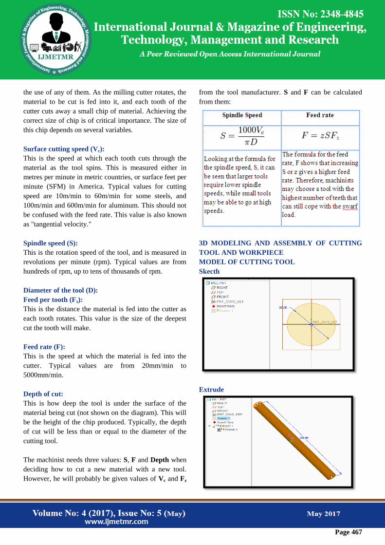
the use of any of them. As the milling cutter rotates, the
material to be cut is fed into it, and each tooth of the
cutter cuts away a small chip of material. Achieving the
correct size of chip is of critical importance. The size of
this chip depends on several variables.
Surface cutting speed (Vc):
This is the speed at which each tooth cuts through the
material as the tool spins. This is measured either in
metres per minute in metric countries, or surface feet per
minute (SFM) in America. Typical values for cutting
speed are 10m/min to 60m/min for some steels, and
100m/min and 600m/min for aluminum. This should not
be confused with the feed rate. This value is also known
as "tangential velocity."
Spindle speed (S):
This is the rotation speed of the tool, and is measured in
revolutions per minute (rpm). Typical values are from
hundreds of rpm, up to tens of thousands of rpm.
Diameter of the tool (D):
Feed per tooth (Fz):
This is the distance the material is fed into the cutter as
each tooth rotates. This value is the size of the deepest
cut the tooth will make.
Feed rate (F):
This is the speed at which the material is fed into the
cutter. Typical values are from 20mm/min to
5000mm/min.
Depth of cut:
This is how deep the tool is under the surface of the
material being cut (not shown on the diagram). This will
be the height of the chip produced. Typically, the depth
of cut will be less than or equal to the diameter of the
cutting tool.
The machinist needs three values: S, F and Depth when
deciding how to cut a new material with a new tool.
However, he will probably be given values of Vc and Fz
from the tool manufacturer. S and F can be calculated
from them:
3D MODELING AND ASSEMBLY OF CUTTING
TOOL AND WORKPIECE
MODEL OF CUTTING TOOL
Skecth
Extrude
Page 468
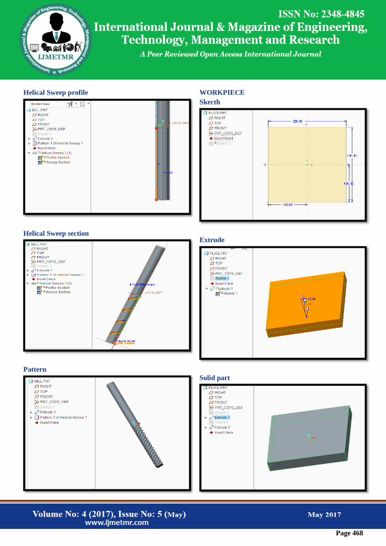
Helical Sweep profile
Helical Sweep section
Pattern
WORKPIECE
Skecth
Extrude
Solid part

Page 469
Assembly
Drafting
Cutting Tool
THERMAL ANALYSIS
MATERIAL PROPERTIES
Cutting Tool – HSS
Thermal conductivity =0.019 W/mm K
Specific Heat – 460J/Kg K
Density = 0.0000081 Kg/mm3
Work Piece – Aluminum alloy 6063
Thermal conductivity =0.2 W/mm K
Specific Heat – 900J/Kg K
Density = 0.0000027 Kg/mm3
CUTTING TOOL MATERIAL - HSS
COOLANT - AIR
TEMPARATURE - 410K
Imported model
Meshed model

Page 470
Temperature
Convection
Temperature
Heat flux
TEMPARATURE - 460K
Temperature
Convection
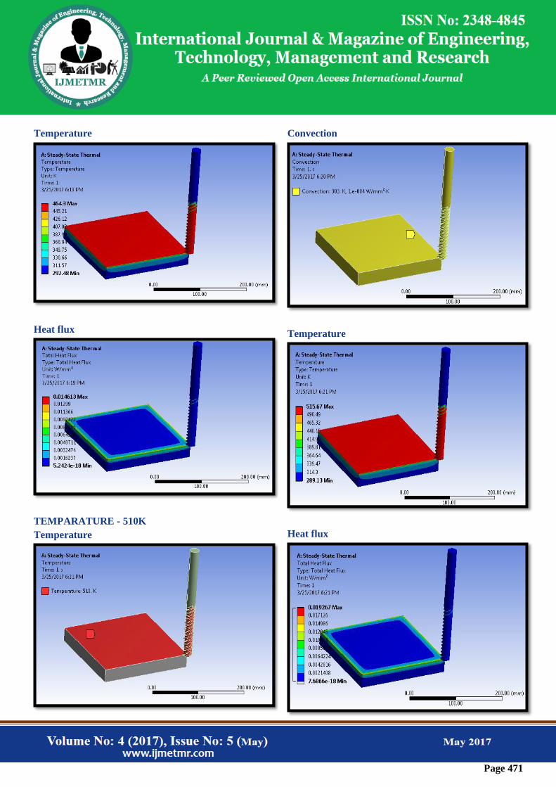
Page 471
Temperature
Heat flux
TEMPARATURE - 510K
Temperature
Convection
Temperature
Heat flux
Page 472
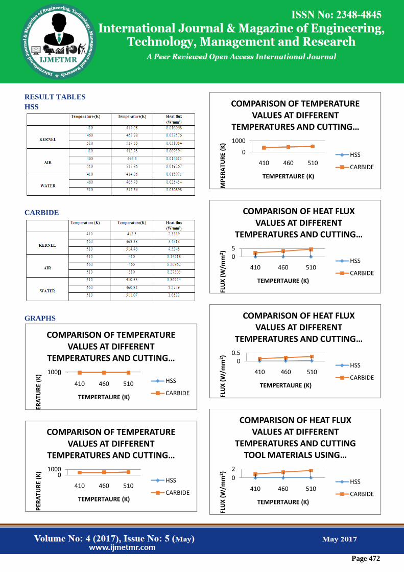
RESULT TABLES
HSS
CARBIDE
GRAPHS
01000
410 460 510
TEM
PER
ATU
RE
(K)
TEMPERTAURE (K)
COMPARISON OF TEMPERATURE VALUES AT DIFFERENT
TEMPERATURES AND CUTTING …
HSS
CARBIDE
01000
410 460 510
TEM
PER
ATU
RE
(K)
TEMPERTAURE (K)
COMPARISON OF TEMPERATURE VALUES AT DIFFERENT
TEMPERATURES AND CUTTING …
HSS
CARBIDE
0
1000
410 460 510
TEM
PER
ATU
RE
(K)
TEMPERTAURE (K)
COMPARISON OF TEMPERATURE VALUES AT DIFFERENT
TEMPERATURES AND CUTTING …
HSS
CARBIDE
05
410 460 510
HEA
T FL
UX
(W
/mm
2 )
TEMPERTAURE (K)
COMPARISON OF HEAT FLUX VALUES AT DIFFERENT
TEMPERATURES AND CUTTING …
HSS
CARBIDE
00.5
410 460 510
HEA
T FL
UX
(W
/mm
2 )
TEMPERTAURE (K)
COMPARISON OF HEAT FLUX VALUES AT DIFFERENT
TEMPERATURES AND CUTTING …
HSS
CARBIDE
0
2
410 460 510
HEA
T FL
UX
(W
/mm
2 )
TEMPERTAURE (K)
COMPARISON OF HEAT FLUX VALUES AT DIFFERENT
TEMPERATURES AND CUTTING TOOL MATERIALS USING …
HSS
CARBIDE

Page 473
CONCLUSION
In this thesis air, water and palm kernel oil are used as
coolants in machining operations. Tungsten carbide and
HSS cutting tools are employed as cutter with different
temperatures. Thermal analysis is done on the parametric
model to determine the effect of different cutting fluids
on the cutters.
Parametric Modeling is done in Creo 2.0 and analysis is
done in Ansys.
By observing the analysis results, the heat transfer rates
are more when the fluid Palm Kernel is used since
thermal flux is more than Air and water.
When compared the values for tool materials, the heat
transfer rates are more for carbide tool than HSS tool.
REFERENCES
1. The Measurement of chip-tool interface Temperature
in the Turning of steel by L. B. Abhang, M.
Hameedullah, International Journal of Computer
Communication and Information System ( IJCCIS), –
Vol2. No1. ISSN: 0976–1349 July – Dec 2010
2. Effect of tool geometry variation on finish turning – A
Review by M. Dogra,V. S. Sharma, J. Dureja, Journal of
Engineering Science and Technology Review 4 (1)
(2011) 1-13
3. Using the Response Surface Method to Optimize the
Turning Process of AISI 12L14 Steel
4. Optimization of Process Parameters of Turning Parts:
A Taguchi Approach by Neeraj Sharma, Renu Sharma
5. The Effect of Tool Construction and Cutting
Parameters on Surface Roughness and Vibration in
Turning of AISI 1045 Steel Using Taguchi Method by
Rogov Vladimir Aleksandrovich, GhorbaniSiamak
6. Parametric investigation of turning process on mild
steel aisi 1018 material by J. M. Gadhiya, P. J. Patel
7. Evaluation and Optimization of Machining Parameter
for turning of EN 8 steel by Vikas B. Magdum, Vinayak
R. Naik
8. Analyses of surface roughness by turning process
using Taguchi method by S. Thamizhmanii, S.
Saparudin, S. Hasan
9. Application of Taguchi Method for Optimizing
Turning Process by the effects of Machining Parameters
by Krishankant, JatinTaneja, MohitBector, Rajesh
Kumar
10. Multi-Objective Optimization of the Cutting Forces
in Turning Operations Using the Grey-Based Taguchi
Method by Yigit
11. Experimental investigation of Material removal rate
in CNC turning using Taguchi method by Kamal, Anish
and M.P.Garg
12. Optimization of Cutting Parameters of Composite
Materials using Genetic Algorithm by Dhavamani and
Alwarsamy
Author Details
Chowdary Manjusha received the B.Tech degree in
mechanical engineering from Godavari Institute of
Engineering and Technology, JNTU, Kakinada, Andhra
Pradesh, India, in 2012 year, and perusing M.Tech in
THERMAL ENGINEERING from Kakinada Institute of
Technology and science, Divili, peddapuram,Andhra
Pradesh, India.
Sri. K.Srilakshmi , M.Tech Assistant professor,
Kakinada Institute of Technology and science, Divili,
peddapuram,Andhra Pradesh, India.
Prof.S.Rajasekhar,M.Tech(Ph.D.) , Associate
professor, Kakinada Institute of Technology and science,
Divili, peddapuram,Andhra Pradesh, India.