Embed Size (px)
Citation preview
Effect Gizmo
User’s Manual
RJM Music Technology, Inc.

Effect Gizmo
User’s Manual
Version 1.0 April 27, 2009
RJM Music Technology, Inc. 2525 Pioneer Ave.
Suite 1 Vista, CA 92081
+1-760-597-9450 email: [email protected]
web: www.rjmmusic.com

Copyright © 2009 RJM Music Technology, Inc. All Rights Reserved
Effect Gizmo, Amp Gizmo, MasterMind, RG-16 and the RJM logo are trademarks of RJM Music Technology, Inc.
v
Table of Contents
Table of Contents.............................................................................................................................................................. vIntroduction ......................................................................................................................................................................1
Effect Gizmo Features............................................................................................................................................................................................1Front Panel ........................................................................................................................................................................2Rear Panel..........................................................................................................................................................................3
Controls and Connectors......................................................................................................................................................................................4Front Panel.................................................................................................................................................................................................................4Rear Panel...................................................................................................................................................................................................................4
Special Features ................................................................................................................................................................7Audio Buffer ..............................................................................................................................................................................................................7Click Stopper .............................................................................................................................................................................................................7Function Switching a.k.a. Controlling Your Amp.........................................................................................................................................7Stereo Loops .............................................................................................................................................................................................................8
Setup Examples.................................................................................................................................................................9MIDI Usage ......................................................................................................................................................................15
MIDI Continuous Controllers............................................................................................................................................................................ 15Bank Selection ....................................................................................................................................................................................................... 15Backing Up Your Settings: SysEx Dump....................................................................................................................................................... 16
Setup Mode .....................................................................................................................................................................17Selecting MIDI Channel and MIDI Options.................................................................................................................................................. 17
MIDI Channels................................................................................................................................................................................................... 17Continuous Controller Ranges ................................................................................................................................................................... 17GCX Compatibility Mode .............................................................................................................................................................................. 18CC Disable .......................................................................................................................................................................................................... 18Bank Select Enable .......................................................................................................................................................................................... 18Saving MIDI Channel and Options ............................................................................................................................................................ 18
Invert Mode ............................................................................................................................................................................................................ 18Momentary Mode ................................................................................................................................................................................................ 18Group Mode ........................................................................................................................................................................................................... 19
Troubleshooting .............................................................................................................................................................21Grounding Issues ............................................................................................................................................................22Specifications ..................................................................................................................................................................23Effect Gizmo MIDI Implementation Chart.....................................................................................................................24Warranty..........................................................................................................................................................................27

1

1
Introduction Congratulations on purchasing the Effect Gizmo audio loop switcher. The Effect Gizmo has been designed to give you total control of your effects devices, effects pedals or other electronic equipment from a single MIDI footswitch. The Effect Gizmo provides twelve audio loops and a professional quality audio buffer, all in a compact, single rack space design. Because the audio loops contain no active circuitry, the Effect Gizmo can work with any effects device regardless of signal level. Either four, or all twelve loops (depending the on the model you purchased) can switch either mono, stereo or balanced signals using ¼” TRS jacks. The last four loops can also double as function switches, allowing you to use them to control channel switching and other features on amplifiers. Effect Gizmo Features
• Twelve audio loops (eight grouped in series with an insert point after the first four loops, and four independent
loops) • Stereo or balanced capability on the last four loops (or on all loops, depending on the model purchased) • Loops 9-12 can be used as function switches to control channel switching on most amplifiers that use ¼”
footswitch jacks • A high-quality audio buffer that can bypassed or moved elsewhere in the audio path • “Click Stopper” technology that reduces the click noise associated with relay-based switchers • Works with all MIDI footswitches • Responds to Program Change and Continuous Controller messages • Easy programmability via front panel buttons and LEDs • Up to 256 programs can be saved in memory • High-quality relays for optimal sonic performance, compatibility and reliability • Supports both latching and momentary switching modes • Provides phantom power to compatible MIDI devices when used with 7-pin MIDI cable
2
Fron
t Pan
el
1 2
3 4
912
1110
Inpu
t
Writ
e8
76
54
32
1Effect G
izm
oAu
dio
Loop
Sw
itche
r
RJM
Mus
icTe
chno
logy
, Inc
.
3
Rea
r Pan
el
24
13
25
20
14
23
22
19
21
20
22
19
21
20
22
19
21
20
22
19
21
16
17
15
18
11
12
6
7 5
8
9 10
26
Out
put 1
-4Fr
om F
ront
MID
I Thr
u /
Out
Out
12/
NO
Retu
rn 1
2Se
nd 1
2/N
CRe
turn
11
Out
11/
NO
Send
11/
NC
In 1
1
Retu
rn 1
0
Out
10/
NO
Send
10/
NC
In 1
0
Retu
rn 7
Retu
rn 6
Send
6
Retu
rn 5
Send
5
Inpu
t 5-8
Retu
rn 3
Send
3
Retu
rn 1
Send
1
Retu
rn 4
Send
4
Retu
rn 2
Send
2
Inpu
t 1-4
Pow
er9V
AC
or
12VD
C
MID
I In
In 1
2
RJM
Mus
ic T
echn
olog
y, In
c.
Send
7
Retu
rn 9
Out
9/N
O
Send
9/N
C
In 9
Out
put 5
-8
Tune
r Out
Retu
rn 8
Send
8Bu
ffer
In
Buff
er O
utC
S O
ut
CS
In
Gnd
Li
ft(in
)

4
Controls and Connectors
Front Panel
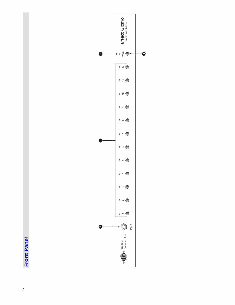
1. Input Jack – This jack is connected to the rear panel From Front jack (7), and will pass a mono or stereo signal through to that connector. 2. Audio Loop Buttons - These buttons turn audio loops 1 through 12 on and off. The LED above each button is lit when the corresponding audio loop is on. 3. Power LED – Lights when the Effect Gizmo is powered on. 4. Write Button – Hold this button for three seconds to save the current settings to memory. The LEDs will flash to confirm. Rear Panel
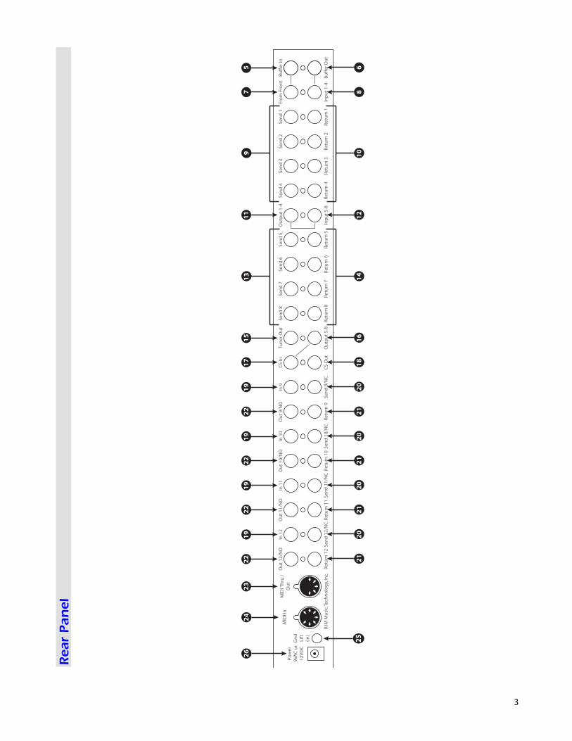
A note about jack normalling Many of the jacks on the Effect Gizmo are normalled, meaning that they are internally connected to another jack inside the unit. A pair of normalled jacks is indicated on the rear panel by a line leading from one jack to another. The signal is normalled from the front panel input, through the buffer, through the first 8 loops, and then through the Click Stopper circuit. All you need to use the first 8 loops are the cables that lead to and from each effects device you wish to connect. The last four loops are not normalled at all – this was done so that they may be used as function switches if desired. Plugging a cable into either one of a pair of normalled jacks breaks the internal connection, so you may use patch cables to change the routing of the signal path to suit your needs. 5. Buffer In – Input to the audio buffer circuit. This jack is normalled to the From Front jack (7) – if nothing is plugged into this jack or the From Front jack (7), then the two jacks are connected together internally. See the Special Features section for more information on the buffer. 6. Buffer Out – Output from the audio buffer circuit. This jack is normalled to the Input 1-4 jack (8) – if nothing is plugged into this jack or the Input 1-4 jack (8), then the two jacks are connected together internally. 7. From Front – Signal from the front panel Input Jack (5) appears at this jack. This jack is normalled to the Buffer In jack (5) – if nothing is plugged into this jack or the Buffer In jack (5), then the two jacks are connected together internally. About Audio Loops 1 through 4 Audio Loops 1 through 4 are connected in series. Each loop is connected internally to the next. When a loop is off, the Send and Return jacks for that loop are bypassed. The audio signal passes through unchanged. Turning the loop on routes the guitar signal through the Send jack and connects the Return jack to the next loop, which inserts the connected effects device in the audio path. 8. Input 1-4 – Input to audio loops 1 through 4. This jack is normalled to the Buffer Out jack (6) – if nothing is plugged into this jack or the Buffer Out jack (6), then the two jacks will be connected together internally. 9. Send 1 through 4 – Connect your effects inputs here. When the loop is on, the audio signal will be output at the send jack. When the loop is off, the send jack is grounded and no signal is output.
5
10. Return 1 through 4 – Connect your effects outputs here. When the loop is on, signal sent to these jacks will be passed through to the next loop. 11. Output 1-4 – Output from loops 1 through 4. This jack is normalled to the Input 5-8 jack (12) – if nothing is plugged into this jack or the Input 5-8 jack (12), then the two jacks will be connected together internally. About Audio Loops 5 through 8 Audio Loops 5 through 8 are connected in series in the same way Loops 1 through 4 are. 12. Input 5-8 – Input to audio loops 5 through 8. This jack is normalled to the Output 1-4 jack (11) – if nothing is plugged into this jack or the Output 1-4 jack (11), then the two jacks will be connected together internally. 13. Send 5 through 8 – Connect your effects inputs here. When the loop is on, the audio signal will be output at the send jack. When the loop is off, the send jack is grounded and no signal is output. 14. Return 5 through 8 – Connect your effects outputs here. When the loop is on, signal sent to these jacks will be passed through to the next loop. 15. Tuner Out – This is an additional output that can be used to connect a tuner. It is connected to the buffer output, so this jack only functions if the buffer is in use. 16. Output 5-8 – Output from loops 5 through 8. This jack is normalled to the CS In jack (17) – if nothing is plugged into this jack or the CS In jack (17), then the two jacks will be connected together internally. 17. CS In – Input to the Click Stopper circuit. This jack is normalled to the Output 5-8 jack (16) – if nothing is plugged into this jack or the Output 5-8 jack (16), then the two jacks will be connected together internally. See the Special Features section for more information on the Click Stopper. 18. CS Out – Output from the Click Stopper circuit. About Audio Loops 9 through 12 Audio loops 9 through 12 are fully isolated – not electrically connected to each other in any way. Each loop has its own discrete input and output. When a loop is off, the Send and Receive jacks for that loop are bypassed, and audio signal passes unchanged from loop input to loop output. When a loop is on, the loop input is connected to the Send jack, and the loop output is connected to the Return jack, which inserts the connected effects device into the audio path. 19. Input (9 through 12) – Signal input to the corresponding audio loop. 20. Send/NC (9 through 12) – Connect your effects inputs here. When the corresponding loop is on, audio signal will be output at this jack. When the corresponding loop is off, this jack is grounded and no signal is output. (NOTE: This jack can also be used as a Normally Closed function switch – see the Special Features section for details). 21. Output/NO (9 through 12) – Signal output from the corresponding audio loop. (NOTE: this jack can also be used as a Normally Open function switch – see the Special Features section for details). 22. Return (9 through 12) – Connect your effects outputs here. When the corresponding loop is on, audio signal feeding this output will be passed through to the loop output. 23. MIDI Thru/Out – Any MIDI commands sent to the MIDI In port (22) are output unchanged through this output. This port also acts as a MIDI output from the purpose of sending MIDI SysEx dumps – see the MIDI Usage section for more details.
6
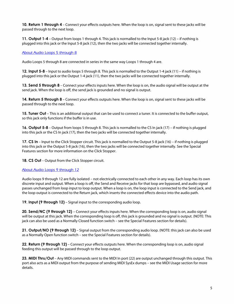
24. MIDI In – Connect your MIDI footswitch controller here to send incoming MIDI commands to the Effect Gizmo. NOTE: If your MIDI footswitch supports phantom power, you can connect a 7-pin MIDI cable here and the Effect Gizmo will provide phantom power to the footswitch. Phantom power is supplied by the same AC adapter that powers the Effect Gizmo. If you use a 9VAC adapter to power the Effect Gizmo, the phantom power output will be 9VAC. If you use a 12VDC adapter, the phantom power output will be 12VDC. 25. Gnd Lift – This switch controls whether or not the Effect Gizmo chassis is grounded. If the button is out, the chassis is grounded. If It is in, the chassis is not grounded. Please note that this button is recessed to prevent it from being pressed accidentally – when the button is “out”, it’s almost flush with the chassis. If you find you have audio hum due to a grounding problem, activating or deactivating this switch may eliminate the hum. Please refer to the Grounding Issues section for more information. 26. Power – Connect a 9VAC, 1 Amp (or 12VDC, 1 Amp) power supply here. Important: Note that the Effect Gizmo uses a 9 Volt AC or 12 Volt DC power supply. Do NOT connect any other power supply to the unit. Many power supplies are very similar in appearance. Connecting the wrong power supply to the Effect Gizmo can damage the unit and void your warranty.
7
Special Features Audio Buffer
Using long cables or many effects may degrade the guitar signal, causing it to lose clarity and definition. The audio buffer is used to “strengthen” the guitar signal and preserve sound quality. The effect may vary from subtle to significant, depending on the length and quality of cables and type of effects used in your rig. Typically, the buffer is placed in the audio path before the first audio loop, but certain pedals such as wah pedals or germanium fuzz pedals work better without a buffer in front of them. In these cases, it’s best to route your signal through these pedals, then through the buffer, and then through the rest of your pedals. The buffer also provides a path to ground, which can either help with - or cause – noise due to grounding issues, depending on the specifics of your rig. See the Grounding Issues section for more details. Click Stopper
The Effect Gizmo uses relays to perform its switching. Relays are the cleanest, most transparent switching method available. The disadvantage of relays is that they can produce a slight click in your audio signal when they switch. This is more noticeable when using a high gain amplifier or overdrive and distortion pedals. The Click Stopper circuit found in the Effect Gizmo is designed to greatly reduce this click noise by muting the audio output briefly when the relays switch. To most effectively use the Click Stopper, it should be the last thing in line before your signal goes into the input of your amplifier or preamp. If you’re using 8 or less pedals in front of your amp, all you need to do is connect the CS Out jack to the input of your amp. All the other connections (except the connections leading to and from each pedal) are done for you internally. If you’re using all 12 audio loops for pedals in front of your amp, you should connect from the output of loop 12 into the input of the Click Stopper (CS In), and the Click Stopper output (CS Out) will connect to the input of your amp. You will also need to make sure your signal is buffered when using the Click Stopper. Running the audio signal through the Effect Gizmo’s audio buffer before it reaches the Click Stopper will insure correct functioning of the Click Stopper and maximize sound quality. Like the buffer, the Click Stopper also provides a path to ground, which can either help with - or cause – noise due to grounding issues, depending on the specifics of your rig. See the Grounding Issues section for more details.
Function Switching a.k.a. Controlling Your Amp
The Effect Gizmo has the ability to control footswitchable features on many amps. This could be channel switching, reverb, tremolo, etc. – anything that is controlled by a ¼” footswitch jack. Loops 9 through 12 can be used for function switching purposes. To use one or more of these loops for this purpose, connect a standard ¼” guitar cable from the Out jack of the loop. Make sure nothing is connected to the In, Send or Return jacks of the loop. Connect the other end of your cable to the footswitch jack of the amp. Pressing the loop button on the Effect Gizmo should now control the same channel or function that your footswitch did. You can save the state of this channel or function for every patch, just like you can for the other audio loops. If your amp has a two button footswitch with a stereo ¼” plug, you can use an insert cable to control it. An insert cable has two mono plugs on one end – these should plug into the outputs of two loops on the Effect Gizmo (any of loops 9-12). The other end of the insert cable has one stereo ¼” plug, and this goes to your footswitch jack. The two loops you selected will control the same channels or functions the amp’s footswitch does.

8
If you have a complex amp with many channels and/or functions, or an amp with an unusual footswitch connector, the Effect Gizmo may not be able to control it. In this case, we recommend our other products such as the Amp Gizmo, Mini Amp Gizmo or RG-16 – all of these are well suited to controlling these amps and are designed to work in conjunction with the Effect Gizmo. These products, and a list of the amps they can control, can be found on our web site. Stereo Loops
Loops 9 through 12 on the Effect Gizmo are stereo capable. If you plug a stereo or TRS (tip-ring-sleeve) cable into these loops, you can switch stereo unbalanced signals or mono balanced signals. Although they are stereo capable, these loops can always be used for standard mono signals – just be sure to use mono cables. If you need to connect to equipment that has separate left and right inputs and outputs, you will need to use insert cables to connect it to the Effect Gizmo. These cables have a stereo connector on one end and split the stereo signal to separate left and right connectors. The Effect Gizmo can also be special ordered with all loops upgraded to stereo capable. Please contact your RJM Music dealer for details.
9
Setu
p E
xam
ple
s
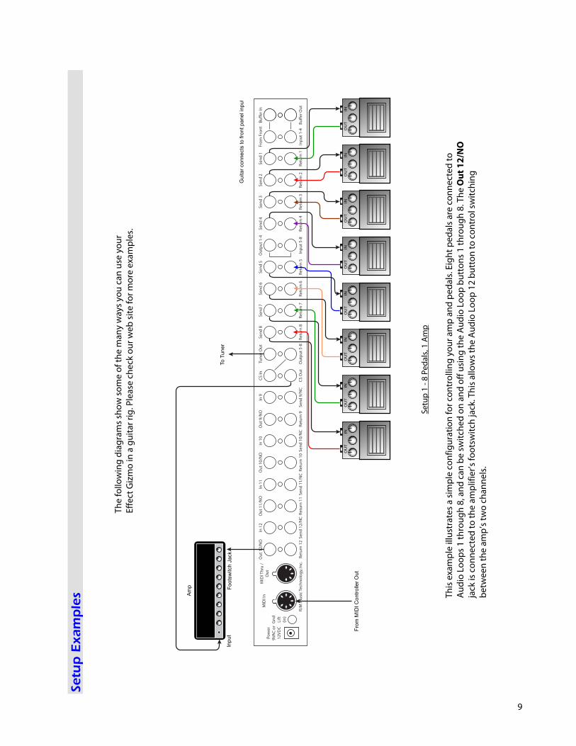
The
follo
win
g di
agra
ms s
how
som
e of
the
man
y w
ays y
ou c
an u
se y
our
Effe
ct G
izm
o in
a g
uita
r rig
. Ple
ase
chec
k ou
r web
site
for m
ore
exam
ples
.
INO
UT
INO
UT
INO
UT
INO
UT
INO
UT
INO
UT
INO
UT
INO
UT
Gu
ita
r co
nn
ects
to
fro
nt
pa
ne
l in
pu
t
Fro
m M
IDI
Co
ntr
olle
r O
ut
To
Tu
ne
r
Fo
ots
witch
Ja
ck
Inp
ut
Am
p
Setu
p 1
- 8 P
edal
s, 1
Amp
This
exam
ple
illus
trat
es a
sim
ple
conf
igur
atio
n fo
r con
trol
ling
your
am
p an
d pe
dals.
Eig
ht p
edal
s are
con
nect
ed to
Au
dio
Loop
s 1 th
roug
h 8,
and
can
be
switc
hed
on a
nd o
ff us
ing
the
Audi
o Lo
op b
utto
ns 1
thro
ugh
8. T
he O
ut 1
2/N
O
jack
is c
onne
cted
to th
e am
plifi
er’s
foot
switc
h ja
ck. T
his a
llow
s the
Aud
io L
oop
12 b
utto
n to
con
trol
switc
hing
be
twee
n th
e am
p’s t
wo
chan
nels.
10
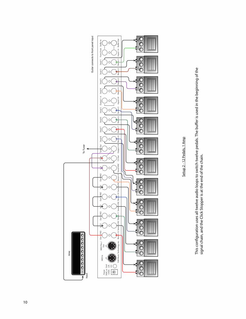
Setu
p 2
- 12
Peda
ls, 1
Am
p
This
conf
igur
atio
n us
es a
ll tw
elve
aud
io lo
ops t
o sw
itch
twel
ve p
edal
s. Th
e bu
ffer i
s use
d in
the
begi
nnin
g of
the
signa
l cha
in, a
nd th
e Cl
ick
Stop
per i
s at t
he e
nd o
f the
cha
in.
INO
UT
INO
UT
INO
UT
INO
UT
INO
UT
INO
UT
INO
UT
INO
UT
INO
UT
INO
UT
INO
UT
INO
UT
RJM
Mus
ic Te
chno
logy
, Inc
.w
ww
.rjm
mus
ic.c
omE!
ect G
izm
o W
iring
Dia
gram
E!ec
t Giz
mo
Wir
ing
Dia
gram
12 p
edal
s, 1
amp,
tune
r
The
guita
r sig
nal p
asse
s fro
m th
e fro
nt p
anel
jack
, thr
ough
the
bu!e
r, th
en th
roug
h th
eal
l 12
audi
o lo
ops,
and
then
thro
ugh
the
Clic
k St
oppe
r circ
uit b
efor
e go
ing
to th
e am
p.
To T
uner
Inpu
t
Am
p
Gui
tar c
onne
cts
to fr
ont p
anel
inpu
t
11
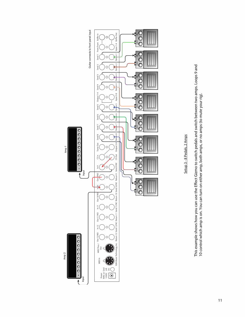
Setu
p 3
- 8 P
edal
s, 2
Amps
This
exam
ple
show
s how
you
can
use
the
Effe
ct G
izm
o to
switc
h pe
dals
and
switc
h be
twee
n tw
o am
ps. L
oops
9 a
nd
10 c
ontr
ol w
hich
am
p is
on. Y
ou c
an tu
rn o
n ei
ther
am
p, b
oth
amps
, or n
o am
ps (t
o m
ute
your
rig)
.
INO
UT
INO
UT
INO
UT
INO
UT
INO
UT
INO
UT
INO
UT
INO
UT
RJM
Mus
ic Te
chno
logy
, Inc
.w
ww
.rjm
mus
ic.c
omE!
ect G
izm
o W
iring
Dia
gram
E!ec
t Giz
mo
Wir
ing
Dia
gram
8 pe
dals,
2 a
mps
The
guita
r sig
nal p
asse
s fro
m th
e fro
nt p
anel
jack
, thr
ough
the
bu!e
r, th
roug
h 8
audi
o lo
ops
and
the
Clic
k St
oppe
r. Lo
ops 9
and
10
are
used
to sp
lit th
e sig
nal t
o tw
o am
ps. U
sing
Loop
s9
and
10, y
ou c
an tu
rn o
n ei
ther
am
p, b
oth
amps
, or n
eith
er (m
ute)
.
Inpu
t
Amp
2
Inpu
t
Amp
1
Gui
tar c
onne
cts
to fr
ont p
anel
inpu
t
12
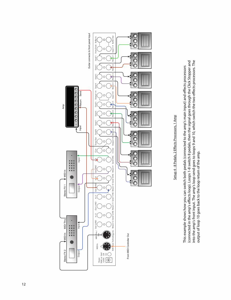
Setu
p 4
- 8 P
edal
s, 2
Effe
cts P
roce
ssor
s, 1
Amp
This
exam
ple
show
s how
you
can
switc
h bo
th p
edal
s (co
nnec
ted
to th
e am
p’s m
ain
inpu
t) an
d ef
fect
s pro
cess
ors
(con
nect
ed in
the
amp’
s effe
cts l
oop)
. Loo
ps 1
-8 sw
itch
8 pe
dals,
then
the
signa
l goe
s thr
ough
the
Clic
k St
oppe
r and
in
to th
e am
p’s f
ront
inpu
t. Th
e am
p’s l
oop
send
goe
s to
loop
s 9 a
nd 1
0, w
hich
switc
h th
e tw
o ef
fect
s pro
cess
ors.
The
outp
ut o
f loo
p 10
goe
s bac
k to
the
loop
retu
rn o
f the
am
p.
INO
UT
INO
UT
INO
UT
INO
UT
INO
UT
INO
UT
INO
UT
INO
UT
RJM
Mus
ic Te
chno
logy
, Inc
.w
ww
.rjm
mus
ic.c
omE!
ect G
izm
o W
iring
Dia
gram
E!ec
t Giz
mo
Wiri
ng D
iagr
am8
peda
ls, 2
e!ec
ts p
roce
ssor
s in
the a
mp’s
e!ec
ts lo
op
The
guita
r sig
nal p
asse
s fro
m th
e fro
nt p
anel
jack
, thr
ough
the
bu!e
r, th
roug
h 8
audi
o lo
ops
and
the
Clic
k St
oppe
r, th
en g
oes t
o th
e am
pli"
er in
put.
The
two
e!ec
ts p
roce
ssor
s are
inlo
ops 9
and
10,
whi
ch a
re in
turn
inse
rted
in th
e am
p’s e
!ect
s loo
p.
Out
put
Inpu
t
Ster
eo F
X 2
MID
I In
Inpu
tO
utpu
t
Ster
eo F
X 1
MID
I Thr
uM
IDI I
n
From
MID
I Con
trolle
r Out
Ret
urn
S
end
Inpu
t
Amp
Gui
tar c
onne
cts
to fr
ont p
anel
inpu
t
13
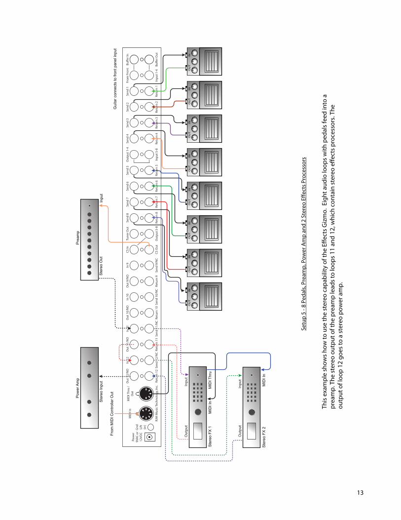
This
exam
ple
show
s how
to u
se th
e st
ereo
cap
abili
ty o
f the
Effe
cts G
izm
o. E
ight
aud
io lo
ops w
ith p
edal
s fee
d in
to a
pr
eam
p. T
he st
ereo
out
put o
f the
pre
amp
lead
s to
loop
s 11
and
12, w
hich
con
tain
ster
eo e
ffect
s pro
cess
ors.
The
outp
ut o
f loo
p 12
goe
s to
a st
ereo
pow
er a
mp.
Setu
p 5
- 8 P
edal
s, Pr
eam
p, P
ower
Am
p an
d 2
Ster
eo E
ffect
s Pro
cess
ors
INO
UT
INO
UT
INO
UT
INO
UT
INO
UT
INO
UT
INO
UT
INO
UT
RJM
Mus
ic Te
chno
logy
, Inc
.w
ww
.rjm
mus
ic.c
omE!
ect G
izm
o W
iring
Dia
gram
E!ec
t Giz
mo
Wir
ing
Dia
gram
8 pe
dals,
pre
amp,
2 st
ereo
e!e
cts p
roce
ssor
s, st
ereo
pow
er a
mp
The
guita
r sig
nal p
asse
s fro
m th
e fro
nt p
anel
jack
, thr
ough
the
bu!e
r, th
roug
h 8
audi
o lo
ops
and
the
Clic
k St
oppe
r, th
en g
oes t
o th
e pr
eam
p. T
he st
ereo
pre
amp
outp
ut si
gnal
is se
nt to
two
ster
eo e!e
cts p
roce
ssor
s in
audi
o lo
ops 1
1 an
d 12
, the
n se
nt to
a st
ereo
pow
er a
mp.
Note:
Das
hed
lines
indi
cate
ster
eo (T
RS) c
onne
ctio
ns.
Pre
amp
Inpu
tS
tere
o O
ut
Pow
er A
mp
Ste
reo
Inpu
t
Out
put
Inpu
t
Inpu
tO
utpu
t
Ste
reo
FX 2
Ste
reo
FX 1
MID
I Thr
u
MID
I In
MID
I In
From
MID
I Con
trolle
r Out
Gui
tar c
onne
cts
to fr
ont p
anel
inpu
t
14
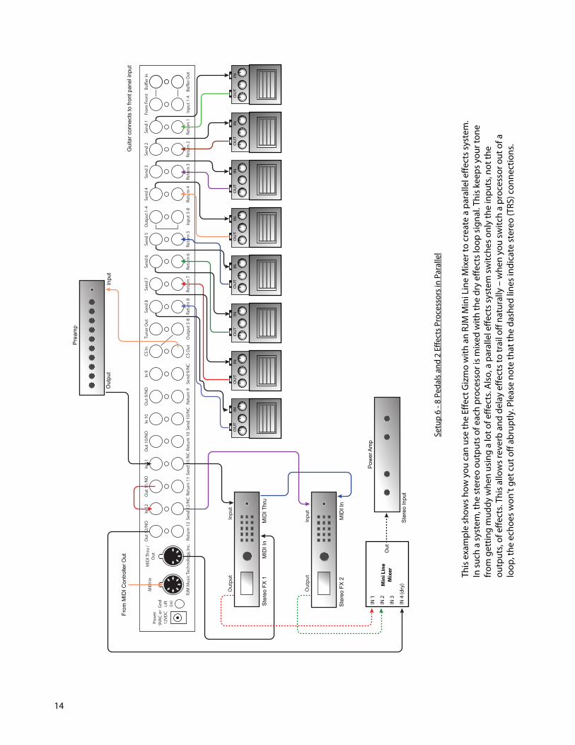
Setu
p 6
- 8 P
edal
s and
2 E
ffect
s Pro
cess
ors i
n Pa
ralle
l
This
exam
ple
show
s how
you
can
use
the
Effe
ct G
izm
o w
ith a
n RJ
M M
ini L
ine
Mix
er to
cre
ate
a pa
ralle
l effe
cts s
yste
m.
In su
ch a
syst
em, t
he st
ereo
out
puts
of e
ach
proc
esso
r is m
ixed
with
the
dry
effe
cts l
oop
signa
l. Th
is ke
eps y
our t
one
from
get
ting
mud
dy w
hen
usin
g a
lot o
f effe
cts.
Also
, a p
aral
lel e
ffect
s sys
tem
switc
hes o
nly
the
inpu
ts, n
ot th
e ou
tput
s, of
effe
cts.
This
allo
ws r
ever
b an
d de
lay
effe
cts t
o tr
ail o
ff na
tura
lly –
whe
n yo
u sw
itch
a pr
oces
sor o
ut o
f a
loop
, the
ech
oes w
on’t
get c
ut o
ff ab
rupt
ly. P
leas
e no
te th
at th
e da
shed
line
s ind
icat
e st
ereo
(TRS
) con
nect
ions
.
INO
UT
INO
UT
INO
UT
INO
UT
INO
UT
INO
UT
INO
UT
INO
UT
IN 1
IN 2
IN 3
IN 4
(dry
)Min
i Lin
eM
ixer
Out
RJM
Mus
ic Te
chno
logy
, Inc
.w
ww
.rjm
mus
ic.c
omE!
ect G
izm
o W
iring
Dia
gram
E!ec
t Giz
mo
Wir
ing
Dia
gram
8 pe
dals,
pre
amp,
2 st
ereo
e!ec
ts p
roce
ssor
s in
para
llel, s
tere
o po
wer
am
p
The
guita
r sig
nal p
asse
s fro
m th
e fro
nt p
anel
jack
, thr
ough
the
bu!e
r, th
roug
h 8
audi
o lo
ops
and
the
Clic
k St
oppe
r, th
en g
oes t
o th
e pr
eam
p. T
he st
ereo
pre
amp
outp
ut si
gnal
is se
nt to
two
ster
eo e
!ect
s pro
cess
ors i
n au
dio
loop
s 11
and
12, m
ixed
in p
aral
lel w
ith th
e dr
y sig
nal,
then
sent
to a
ster
eo p
ower
am
p.
Note:
Das
hed
lines
indi
cate
ster
eo (T
RS) c
onne
ctio
ns.
Out
put
Inpu
t
Inpu
tO
utpu
t
Ster
eo F
X 2
Ster
eo F
X 1
MID
I Thr
u
MID
I In
MID
I In
From
MID
I Con
trolle
r Out
Prea
mp
Inpu
tO
utpu
t
Pow
er A
mp
Ster
eo In
put
Gui
tar c
onne
cts
to fr
ont p
anel
inpu
t

15
MIDI Usage The Effect Gizmo can receive MIDI messages from any MIDI footswitch or other MIDI controller. By storing different settings, or “patches” for different MIDI program numbers, you can automatically recall a stored patch by sending the correct MIDI program number from your footswitch. You can assign which audio loops are on for each and every patch. To save a setting to a MIDI program number: • Select a MIDI program number with your MIDI footswitch or controller. • Manually select the desired state of each Audio Loop using the Effect Gizmo’s front panel buttons. • Hold down the Write Button (4) until the LEDs flash. You can save up to 256 patches, using MIDI program numbers 1 through 128 in MIDI banks 0 and 1. MIDI Continuous Controllers
In addition to supporting MIDI Program Change messages, the Effect Gizmo also supports MIDI Continuous Controller (CC) messages. Using a MIDI controller capable of sending CC messages, you can assign a button on the controller to control an individual loop. For example, you can have a button on your controller assigned to turn an overdrive pedal on or off without affecting any of the other loops. By default, the following continuous controller numbers are used:
Audio Loop CC number Loop 1 80 Loop 2 81 Loop 3 82 Loop 4 83 Loop 5 84 Loop 6 85 Loop 7 86 Loop 8 87 Loop 9 88
Loop 10 89 Loop 11 90 Loop 12 91
The Continuous Controller ranges can be adjusted in Setup Mode. Each Continuous Controller message has a value assigned to it. Values in the range of 0…63 will turn a loop or switch off, and values of 64…127 will turn it on. Please note that Continuous Controller messages operate exactly the same as pressing buttons on the front panel. All Setup Mode options such as invert, group and momentary modes will be in effect when processing CC messages. Bank Selection
The Effect Gizmo can store programs in MIDI banks 0 and 1, for a total of 256 programs. Continuous Controller #0 (Bank MSB) is used to select the current MIDI bank. Bank numbers above bank 1 are ignored. By default, bank selection is disabled. You can enable bank selection using Setup Mode (see Setup Mode section).

16
Backing Up Your Settings: SysEx Dump
A SysEx (System Exclusive) data dump will send the current Effect Gizmo system configuration out through the MIDI Thru/Out port. You can then save this data to your computer, or copy the settings directly to another Effect Gizmo. Hold down the Audio Loop 5 button while powering up the Effect Gizmo, and the Effect Gizmo will immediately send the SysEx Dump. It only takes a couple of seconds to complete. If you wish to copy settings from on Effect Gizmo to another, connect the MIDI Thru/Out jack of the transmitting unit to the MIDI In jack of the receiving unit, then power up the transmitting unit while holding down the Audio Loop 5 button. (Note that the receiving Effect Gizmo must be powered on and not in Setup Mode in order to receive a SysEx dump.) The receiving unit will display a progress bar on its front panel LEDs. The transfer goes very quickly, taking only a couple of seconds. In the case of an error, the receiving unit will flash all LEDs 5 times. Once the transfer completes, the receiving unit will reset, then return to normal operating mode. The receiving unit now has an exact copy of the transmitting unit’s settings.
17
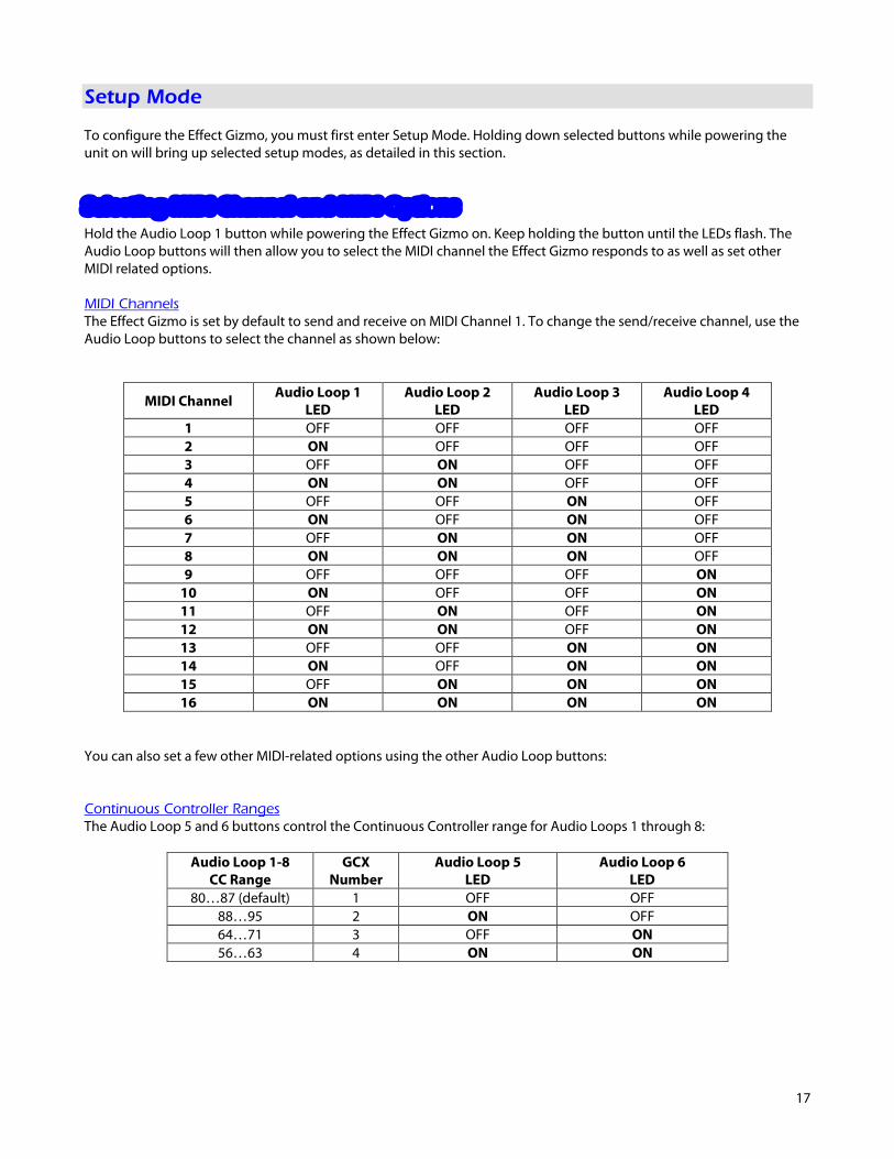
Setup Mode To configure the Effect Gizmo, you must first enter Setup Mode. Holding down selected buttons while powering the unit on will bring up selected setup modes, as detailed in this section. Selecting MIDI Channel and MIDI Options
Hold the Audio Loop 1 button while powering the Effect Gizmo on. Keep holding the button until the LEDs flash. The Audio Loop buttons will then allow you to select the MIDI channel the Effect Gizmo responds to as well as set other MIDI related options. MIDI Channels The Effect Gizmo is set by default to send and receive on MIDI Channel 1. To change the send/receive channel, use the Audio Loop buttons to select the channel as shown below:
MIDI Channel Audio Loop 1 LED
Audio Loop 2 LED
Audio Loop 3 LED
Audio Loop 4 LED
1 OFF OFF OFF OFF 2 ON OFF OFF OFF 3 OFF ON OFF OFF 4 ON ON OFF OFF 5 OFF OFF ON OFF 6 ON OFF ON OFF 7 OFF ON ON OFF 8 ON ON ON OFF 9 OFF OFF OFF ON
10 ON OFF OFF ON 11 OFF ON OFF ON 12 ON ON OFF ON 13 OFF OFF ON ON 14 ON OFF ON ON 15 OFF ON ON ON 16 ON ON ON ON
You can also set a few other MIDI-related options using the other Audio Loop buttons: Continuous Controller Ranges The Audio Loop 5 and 6 buttons control the Continuous Controller range for Audio Loops 1 through 8:
Audio Loop 1-8 CC Range
GCX Number
Audio Loop 5 LED
Audio Loop 6 LED
80…87 (default) 1 OFF OFF 88…95 2 ON OFF 64…71 3 OFF ON 56…63 4 ON ON
18
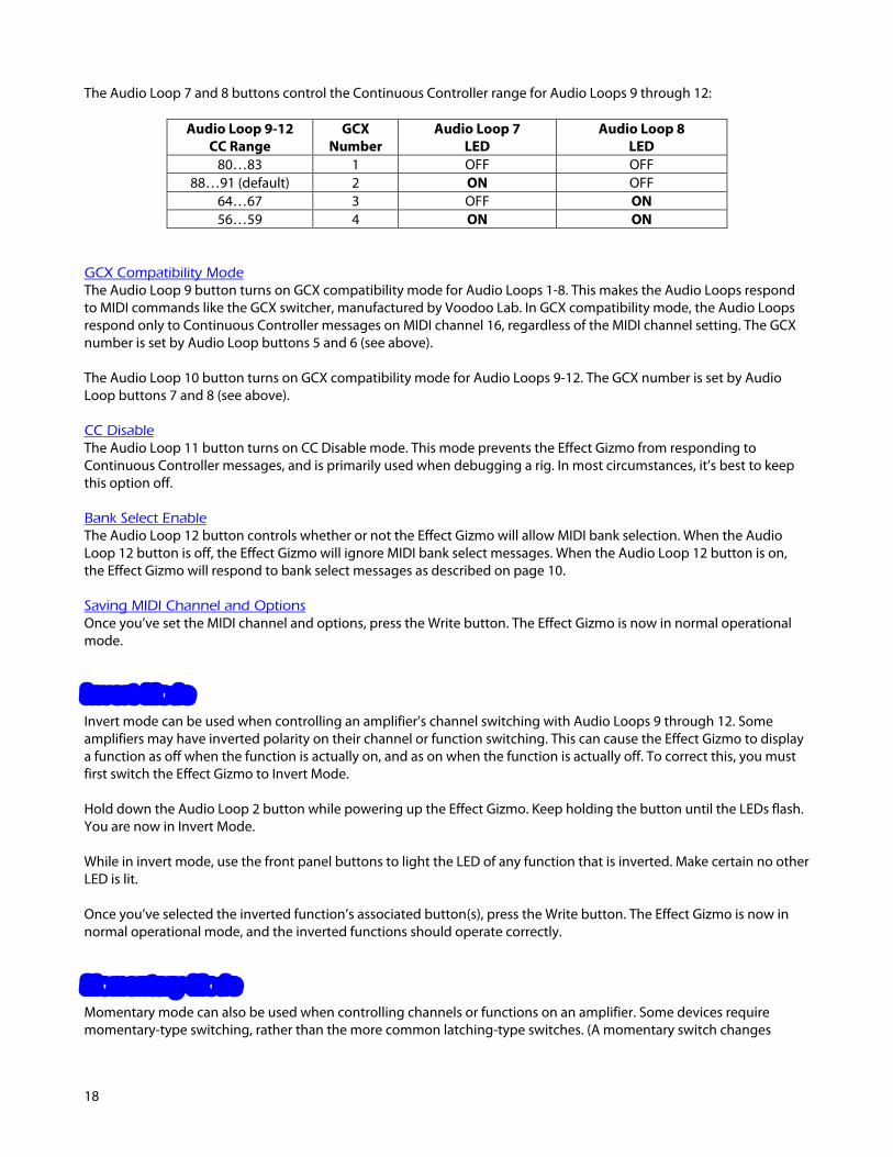
The Audio Loop 7 and 8 buttons control the Continuous Controller range for Audio Loops 9 through 12:
Audio Loop 9-12 CC Range
GCX Number
Audio Loop 7 LED
Audio Loop 8 LED
80…83 1 OFF OFF 88…91 (default) 2 ON OFF
64…67 3 OFF ON 56…59 4 ON ON
GCX Compatibility Mode The Audio Loop 9 button turns on GCX compatibility mode for Audio Loops 1-8. This makes the Audio Loops respond to MIDI commands like the GCX switcher, manufactured by Voodoo Lab. In GCX compatibility mode, the Audio Loops respond only to Continuous Controller messages on MIDI channel 16, regardless of the MIDI channel setting. The GCX number is set by Audio Loop buttons 5 and 6 (see above). The Audio Loop 10 button turns on GCX compatibility mode for Audio Loops 9-12. The GCX number is set by Audio Loop buttons 7 and 8 (see above). CC Disable The Audio Loop 11 button turns on CC Disable mode. This mode prevents the Effect Gizmo from responding to Continuous Controller messages, and is primarily used when debugging a rig. In most circumstances, it’s best to keep this option off. Bank Select Enable The Audio Loop 12 button controls whether or not the Effect Gizmo will allow MIDI bank selection. When the Audio Loop 12 button is off, the Effect Gizmo will ignore MIDI bank select messages. When the Audio Loop 12 button is on, the Effect Gizmo will respond to bank select messages as described on page 10. Saving MIDI Channel and Options Once you’ve set the MIDI channel and options, press the Write button. The Effect Gizmo is now in normal operational mode. Invert Mode
Invert mode can be used when controlling an amplifier’s channel switching with Audio Loops 9 through 12. Some amplifiers may have inverted polarity on their channel or function switching. This can cause the Effect Gizmo to display a function as off when the function is actually on, and as on when the function is actually off. To correct this, you must first switch the Effect Gizmo to Invert Mode. Hold down the Audio Loop 2 button while powering up the Effect Gizmo. Keep holding the button until the LEDs flash. You are now in Invert Mode. While in invert mode, use the front panel buttons to light the LED of any function that is inverted. Make certain no other LED is lit. Once you’ve selected the inverted function’s associated button(s), press the Write button. The Effect Gizmo is now in normal operational mode, and the inverted functions should operate correctly. Momentary Mode
Momentary mode can also be used when controlling channels or functions on an amplifier. Some devices require momentary-type switching, rather than the more common latching-type switches. (A momentary switch changes

19
OFF/ON state by closing its contacts for a short time and then re-opening them. In momentary mode, the Effect Gizmo switches will close for 100 milliseconds before opening again.) To enter momentary mode, hold down the Audio Loop 3 button while powering up the Effect Gizmo. Keep holding the button until the LEDs flash. Use the front panel buttons to light the LED of any function that needs to be momentary. Make certain that no other LED is lit. Once you’ve selected the buttons for the momentary functions, press the Write button. The Effect Gizmo is now in normal operational mode and the momentary functions should operate correctly. Group Mode
The Group feature allows you define a group of buttons where pressing one button of the group turns that button on and turns all other buttons in the group off. This is typically used for function switches that control which channel is selected on an amplifier. This prevents the Effect Gizmo from trying to activate more than one amp channel at a time. To enter group mode, hold down the Audio Loop 4 button while powering up the Effect Gizmo. Keep holding the button until the LEDs flash. Use the front panel buttons to light the LED of any function that should be in the group. Make sure that no other LEDs are lit. Note: The groups for Audio Loops 1-6 and Audio Loops 7-12 are separate. Pressing a button in the Audio Loop 1-6 range only affects loops 1-6. Pressing a button in the Audio Loop 7-12 range only affects loops 7-12. Once you’ve selected the loops that need to be grouped, press the Write button. The Effect Gizmo is now in normal operational mode and the grouped buttons will now only allow one button to be selected at a time.

20
21
Troubleshooting Problem: The LEDs don’t flash when you hold down the Write Button. Solution: The Effect Gizmo did not receive a MIDI Program Change message. First, verify that you have a valid MIDI connection. The MIDI output of your MIDI controller should be connected to the MIDI input of the Effect Gizmo by a MIDI cable that’s known to be working correctly. The next most likely cause is that the Effect Gizmo is set to a different MIDI channel than your MIDI controller. Check both devices to insure that they’re set to the same channel. On the Effect Gizmo, the MIDI channel is set to 1 by default and can be changed in Setup Mode. Problem: There is excessive hum in the audio signal. Solution: There are a number of reasons that this might happen, but it’s often a ground loop or other grounding problem. Please refer to the Grounding Issues section of this manual. Problem: The signal coming out of the buffer is too loud, or is clipped. Solution: There is a buffer level adjustment inside the Effect Gizmo. This is set to unity gain at the factory, but can be adjusted to provide a boost. Remove the Effect Gizmo lid (you need to remove two screws on the top, two on each side, and one on the top center of the front panel). The level adjustment is a small blue trimpot near the front panel input jack. Using a Philips screwdriver, gently turn it all the way counterclockwise for unity gain, or clockwise for a volume boost. More troubleshooting tips can be found in the FAQ section of www.rjmmusic.com.
22
Grounding Issues Guitar rigs are complex electrical systems, and rigs with switching systems are among the most complex. The more complex the rig, the more likely you are to encounter grounding issues. Every audio path in the system must be shielded, with a good connection to ground, or you may get audio hum or buzz due to electromagnetic interference. However, if there are too many connections to ground, you can get a ground loop, which also causes hum. So, if you’re experiencing hum, what do you do? Step 1: Press the Gnd Lift button on the back of the Effect Gizmo. This will either connect or disconnect the ground connection to the Effect Gizmo’s metal enclosure. (In means disconnected (lifted), out means connected). If you’re lucky, that will solve the problem. Step 2: Are you using either the buffer or Click Stopper? If either is connected in your audio path, then you can skip to Step 3. If neither is connected, try using the buffer. This may provide a needed path to ground. Also, for this test, make sure that the Gnd Lift switch is in the out (connected) position. Step 3: Check what you’re using to power your effect pedals. A multiple output power supply that doesn’t have isolated outputs is a common source of ground loops. Power supplies that have “daisy chain” power cords, where there are multiple power connectors on a single cord are definitely not isolated, and there are many other non-isolated culprits on the market. You can test for isolation by unplugging the power cable from every pedal. If the hum goes away, you need to upgrade to a better (isolated) power supply! Step 3: If you have more than one amp connected, disconnect the audio connection(s) to one of the two amps. If the hum goes away, you need an isolation transformer to isolate either the audio or power connection on the second amp.
Step 4: If you’re running a split effects setup where some pedals are connected to the amp’s input and others are connected in the amp’s loop, you should try to use an isolation transformer on the lead running from the amp’s loop return to the Effect Gizmo. Alternately, you can use a ground lift cable1 - it can work as well as an isolation transformer. Step 5: If none of the above steps have helped, you’ll need to do some detective work. Begin disconnecting your effects, starting with any rack-mounted effects. At some point, the hum will stop (at least, we hope so!) You will need to use an isolation transformer or ground lift cable on the lead coming out of the effect’s output (and possibly the input as well). Do this for the last effect you disconnected, and start reconnecting everything. If the hum comes back, isolate the last effects device you just connected. Repeat this until you are hum free. This is only a brief guide giving you the basic steps – there are, unfortunately, many other ways for ground loops to find their way into your rig. If you can’t figure it out, you may need to enlist the services of a competent tech – someone who’s used to chasing down these kinds of problems.
1 A ground lift cable is an audio cable that has the shield or ground disconnected on one side. They’re very useful to have around when building a guitar rig!
23
Specifications
Dimensions Standard 1U EIA rack enclosure 19 (W) x 1.75 (H) x 7.25 (D) inches 48.3 (W) x 4.5 (H) x 18.5 (D) cm
Weight 4 lbs, 9 oz
2.1 kg
Power 9VAC @ 550mA, 12VDC also acceptable (9VAC @ 700mA for full-stereo model) 5.5mm OD, 2.5mm ID x 9.5mm barrel connector
Phantom Power Provided over pins 6 and 7 of the MIDI In jack
Voltage provided is the same as power applied at the Effect Gizmo power jack 9VAC, maximum 450mA current when using provided AC adaptor (max. 300mA for full stereo version with provided AC adaptor)
Memory 256 programs, arranged in 2 banks of 128
Memory is non-volatile and requires no backup battery
24
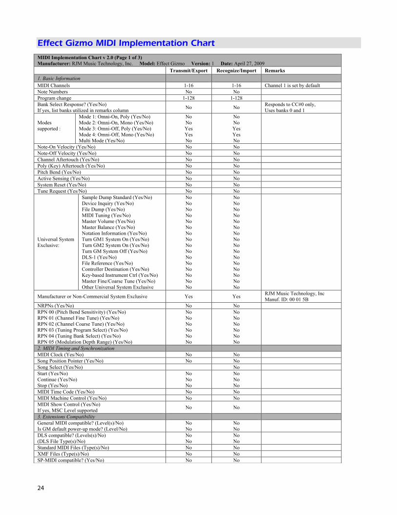
Effect Gizmo MIDI Implementation Chart MIDI Implementation Chart v 2.0 (Page 1 of 3)
Manufacturer: RJM Music Technology, Inc. Model: Effect Gizmo Version: 1 Date: April 27, 2009 Transmit/Export Recognize/Import Remarks 1. Basic Information MIDI Channels 1-16 1-16 Channel 1 is set by default Note Numbers No No Program change 1-128 1-128 Bank Select Response? (Yes/No) If yes, list banks utilized in remarks column No No Responds to CC#0 only,
Uses banks 0 and 1
Modes supported :
Mode 1: Omni-On, Poly (Yes/No) Mode 2: Omni-On, Mono (Yes/No) Mode 3: Omni-Off, Poly (Yes/No) Mode 4: Omni-Off, Mono (Yes/No) Multi Mode (Yes/No)
No No Yes Yes No
No No Yes Yes No
Note-On Velocity (Yes/No) No No Note-Off Velocity (Yes/No) No No Channel Aftertouch (Yes/No) No No Poly (Key) Aftertouch (Yes/No) No No Pitch Bend (Yes/No) No No Active Sensing (Yes/No) No No System Reset (Yes/No) No No Tune Request (Yes/No) No No
Universal System Exclusive:
Sample Dump Standard (Yes/No) Device Inquiry (Yes/No) File Dump (Yes/No) MIDI Tuning (Yes/No) Master Volume (Yes/No) Master Balance (Yes/No) Notation Information (Yes/No) Turn GM1 System On (Yes/No) Turn GM2 System On (Yes/No) Turn GM System Off (Yes/No) DLS-1 (Yes/No) File Reference (Yes/No) Controller Destination (Yes/No) Key-based Instrument Ctrl (Yes/No) Master Fine/Coarse Tune (Yes/No) Other Universal System Exclusive
No No No No No No No No No No No No No No No No
No No No No No No No No No No No No No No No No
Manufacturer or Non-Commercial System Exclusive Yes Yes RJM Music Technology, Inc Manuf. ID: 00 01 5B
NRPNs (Yes/No) No No RPN 00 (Pitch Bend Sensitivity) (Yes/No) RPN 01 (Channel Fine Tune) (Yes/No) RPN 02 (Channel Coarse Tune) (Yes/No) RPN 03 (Tuning Program Select) (Yes/No) RPN 04 (Tuning Bank Select) (Yes/No) RPN 05 (Modulation Depth Range) (Yes/No)
No No No No No No
No No No No No No
2. MIDI Timing and Synchronization MIDI Clock (Yes/No) No No Song Position Pointer (Yes/No) No No Song Select (Yes/No) No Start (Yes/No) Continue (Yes/No) Stop (Yes/No)
No No No
No No No
MIDI Time Code (Yes/No) No No MIDI Machine Control (Yes/No) No No MIDI Show Control (Yes/No) If yes, MSC Level supported No No
3. Extensions Compatibility General MIDI compatible? (Level(s)/No) Is GM default power-up mode? (Level/No)
No No
No No
DLS compatible? (Levels(s)/No) (DLS File Type(s)/No)
No No
No No
Standard MIDI Files (Type(s)/No) No No XMF Files (Type(s)/No) No No SP-MIDI compatible? (Yes/No) No No

25
MIDI Implementation Chart v 2.0 (Page 2 of 3)
Manufacturer: RJM Music Technology, Inc. Model: Effect Gizmo Version: 1 Date: April 27, 2009 Control # Function Transmitted (Y/N) Recognized (Y/N) Remarks
0 Bank Select (MSB) N Y Banks 0 and 1 only 1 Modulation Wheel (MSB) N N 2 Breath Controller (MSB) N N 3 N N 4 Foot Controller (MSB) N N 5 Portamento Time (MSB) N N 6 Data Entry (MSB) N N 7 Channel Volume (MSB) N N 8 Balance (MSB) N N 9 N N
10 Pan (MSB) N N 11 Expression (MSB) N N 12 Effect Control 1 (MSB) N N 13 Effect Control 2 (MSB) N N 14 N N 15 N N 16 General Purpose Controller 1 (MSB) N N 17 General Purpose Controller 2 (MSB) N N 18 General Purpose Controller 3 (MSB) N N 19 General Purpose Controller 4 (MSB) N N 20 N N 21 N N 22 N N 23 N N 24 N N 25 N N 26 N N 27 N N 28 N N 29 N N 30 N N 31 N N 32 Bank Select (LSB) N N Use CC#0 instead 33 Modulation Wheel (LSB) N N 34 Breath Controller (LSB) N N 35 N N 36 Foot Controller (LSB) N N 37 Portamento Time (LSB) N N 38 Data Entry (LSB) N N 39 Channel Volume (LSB) N N 40 Balance (LSB) N N 41 N N 42 Pan (LSB) N N 43 Expression (LSB) N N 44 Effect Control 1 (LSB) N N 45 Effect Control 2 (LSB) N N 46 N N 47 N N 48 General Purpose Controller 1 (LSB) N N 49 General Purpose Controller 2 (LSB) N N 50 General Purpose Controller 3 (LSB) N N 51 General Purpose Controller 4 (LSB) N N 52 N Y 53 N Y 54 N Y 55 N Y 56 N Y Alt. CC Range 2 57 N Y Alt. CC Range 2 58 N Y Alt. CC Range 2 59 N Y Alt. CC Range 2 60 N Y Alt. CC Range 2 61 N Y Alt. CC Range 2 62 N Y Alt. CC Range 2 63 N Y Alt. CC Range 2
26
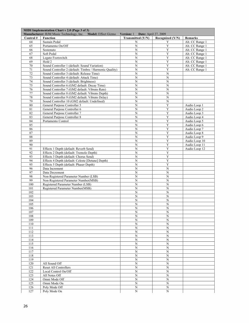
MIDI Implementation Chart v 2.0 (Page 3 of 3)
Manufacturer: RJM Music Technology, Inc. Model: Effect Gizmo Version: 1 Date: April 27, 2009 Control # Function Transmitted (Y/N) Recognized (Y/N) Remarks
64 Sustain Pedal N Y Alt. CC Range 1 65 Portamento On/Off N Y Alt. CC Range 1 66 Sostenuto N Y Alt. CC Range 1 67 Soft Pedal N Y Alt. CC Range 1 68 Legato Footswitch N Y Alt. CC Range 1 69 Hold 2 N Y Alt. CC Range 1 70 Sound Controller 1 (default: Sound Variation) N Y Alt. CC Range 1 71 Sound Controller 2 (default: Timbre / Harmonic Quality) N Y Alt. CC Range 1 72 Sound Controller 3 (default: Release Time) N N 73 Sound Controller 4 (default: Attack Time) N N 74 Sound Controller 5 (default: Brightness) N N 75 Sound Controller 6 (GM2 default: Decay Time) N N 76 Sound Controller 7 (GM2 default: Vibrato Rate) N N 77 Sound Controller 8 (GM2 default: Vibrato Depth) N N 78 Sound Controller 9 (GM2 default: Vibrato Delay) N N 79 Sound Controller 10 (GM2 default: Undefined) N N 80 General Purpose Controller 5 N Y Audio Loop 1 81 General Purpose Controller 6 N Y Audio Loop 2 82 General Purpose Controller 7 N Y Audio Loop 3 83 General Purpose Controller 8 N Y Audio Loop 4 84 Portamento Control N Y Audio Loop 5 85 N Y Audio Loop 6 86 N Y Audio Loop 7 87 N Y Audio Loop 8 88 N Y Audio Loop 9 89 N Y Audio Loop 10 90 N Y Audio Loop 11 91 Effects 1 Depth (default: Reverb Send) N Y Audio Loop 12 92 Effects 2 Depth (default: Tremolo Depth) N Y 93 Effects 3 Depth (default: Chorus Send) N Y 94 Effects 4 Depth (default: Celeste [Detune] Depth) N Y 95 Effects 5 Depth (default: Phaser Depth) N Y 96 Data Increment N N 97 Data Decrement N N 98 Non-Registered Parameter Number (LSB) N N 99 Non-Registered Parameter Number(MSB) N N
100 Registered Parameter Number (LSB) N N 101 Registered Parameter Number(MSB) N N 102 N N 103 N N 104 N N 105 N N 106 N N 107 N N 108 N N 109 N N 110 N N 111 N N 112 N N 113 N N 114 N N 115 N N 116 N N 117 N N 118 N N 119 N N 120 All Sound Off N N 121 Reset All Controllers N N 122 Local Control On/Off N N 123 All Notes Off N N 124 Omni Mode Off N N 125 Omni Mode On N N 126 Poly Mode Off N N 127 Poly Mode On N N

27
Warranty RJM Music Technology, Inc. warrants this product against any defects in material or workmanship for a period of one year from the original date of purchase. Should you experience any difficulty with this RJM Music product, please contact us as described below. If it is determined that the product has become defective within the warranty period and must be returned to the factory, RJM Music Technology will issue a Returned Merchandise Authorization (RMA) number and shipping and packaging instructions. RJM Music Technology will repair or replace the product free of charge, provided it is returned freight prepaid to RJM Music Technology with a copy of a valid receipt and RMA number. Return shipping will be paid by RJM Music Technology within the U.S. only. This warranty is transferable provided the current owner has the original dated purchase receipt and can provide a copy of it when submitting the warranty claim. This warranty shall not apply to any goods that have been repaired or altered by anyone other than RJM Music Technology, Inc. or an RJM Music Technology authorized service center. This warranty does not cover damage to the product resulting from accidents or misuse. This is your sole warranty. There are no warranties which extend beyond the terms described herein. RJM Music Technology, Inc. 2525 Pioneer Ave. Suite 1 Vista, CA 92081 +1-760-597-9450 E-Mail: [email protected]

28