Embed Size (px)
Citation preview

PES-05-01-04-D 規 定帳票
電)Pど ど
Page:1/13
MANUAL No,PES― A40-018
o c u I I l e n t n a l r l e
Siow Blow Fuse L TYPE
REViSiON
ISSUE DATE
FILE No.
iC
:'07.9.27
闘ewed b毘彩 ιAttr
REViSiONiCMANUAL Noo PES―A40-018
issued by μ

PES-05-01-04-D 規定帳票
Page: 2/13
REVISION HISTORY REVISION
NUMBER DATE PAGE CONTENTS
NEW ESTABLISHMENT 08MAR04
A 27MAY04 ALL Add 150A.
B 06JUL05 6 Correct the mistake. 2-(3)-2 → 3-(4)
C 27SEP07 13 Since “JIS K 6301” had been voided, the Standard
Material number had change.
MANUAL No.PES-A40-018 REVISION:C

PES-05-01-04-D 規定帳票
Page: 3/13
SERVICE CONDITIONS (Table 1)
Item Details
・ Actual-vehicle mounting position ・ Service power supply ・ Ambient temperature
Fuse box from the engine compartment and passenger compartment 12V and 36V battery -40 to 100 degC
RATINGS (Table 2)
Item Specifications
・ Rated voltage ・ Rated current ・ Shape
58V DC or less
Rated current A Color of case
30 Orange 40 Green 50 Red 60 Yellow 70 Brown 80 White
100 Blue 125 Pink 150 Gray
<Reference> In according with product drawings.
Ampere marking
Ampere marking
MANUAL No.PES-A40-018 REVISION:C
PES-05-01-04-D 規定帳票
Page: 4/13
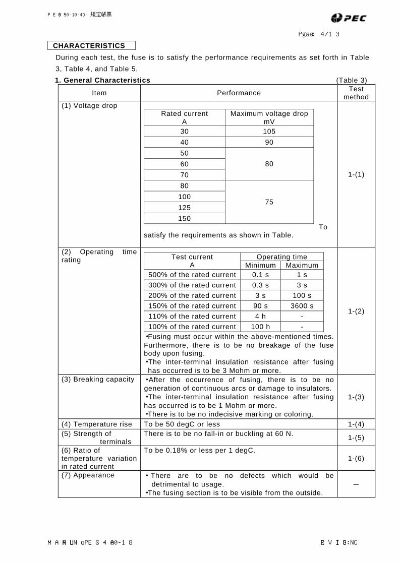
CHARACTERISTICS
During each test, the fuse is to satisfy the performance requirements as set forth in Table 3, Table 4, and Table 5. 1. General Characteristics (Table 3)
Item Performance Test method
(1) Voltage drop To
satisfy the requirements as shown in Table.
Rated current A
Maximum voltage drop mV
30 105 40 90 50 60 70
80
80 100 125 150
75
1-(1)
(2) Operating time rating
・Fusing must occur within the above-mentioned times. Furthermore, there is to be no breakage of the fuse body upon fusing. ・The inter-terminal insulation resistance after fusing
has occurred is to be 3 Mohm or more.
Operating time Test current A Minimum Maximum
500% of the rated current 0.1 s 1 s 300% of the rated current 0.3 s 3 s 200% of the rated current 3 s 100 s 150% of the rated current 90 s 3600 s 110% of the rated current 4 h - 100% of the rated current 100 h -
1-(2)
(3) Breaking capacity ・ After the occurrence of fusing, there is to be no generation of continuous arcs or damage to insulators.・The inter-terminal insulation resistance after fusing has occurred is to be 1 Mohm or more. ・There is to be no indecisive marking or coloring.
1-(3)
(4) Temperature rise To be 50 degC or less 1-(4) (5) Strength of
terminals There is to be no fall-in or buckling at 60 N. 1-(5)
(6) Ratio of temperature variation in rated current
To be 0.18% or less per 1 degC. 1-(6)
(7) Appearance ・ There are to be no defects which would be detrimental to usage.
・The fusing section is to be visible from the outside. -
MANUAL No.PES-A40-018 REVISION:C

PES-05-01-04-D 規定帳票
Page: 5/13
2. Strength Characteristics (Table 4)
Item Performance Test method
(1)Cover latching strength
10 N or more 2-(1)
(2)Element latching strength
60 N or more 2-(2)
(3) Drop impact strength There is to be no terminal bending, housing breakage, or any other factors which would be detrimental to usage.
2-(3)
(4) Compression fracture strength
200 N or more 2-(4)
3. Durability Characteristics (Table 5)
Item Properties Test method
(1) Transient current cycling 3-(1)
(2) Vibration durability 3-(2) (3) Accelerated ageing 3-(3) (4) Temperature/vibration 3-(4) (5) Dust resistance 3-(5) (6) Fuel resistance
The requirements of voltage drop, operating time rating, terminal strength and appearance from (Table 3) are to be satisfied.
3-(6) (7) Oil resistance There is to be no corrosion, cracking, deformation,
or any other factors which would impair functionality.
3-(7)
(8) Thermal shock resistance
The requirements of voltage drop, operating time rating, terminal strength and appearance from (Table 3) are to be satisfied.
3-(8)
MANUAL No.PES-A40-018 REVISION:C

PES-05-01-04-D 規定帳票
Page: 6/13
TEST METHODS FOR FUSE BLOCK
TEST CONDITIONS
Unless otherwise specified, the following conditions are to be implemented in the testing of fuses. (1) All electrical testing is to be carried out with DC which is maintained within a +/-1%
tolerance range and in an environment at a temperature of 23+/-5 degC; furthermore, fuses are to be mounted on a test fixture as shown in Figure 1.
(2) Connection cables which are used in electrical testing are to satisfy JIS C 3406, JASO D611, or ISO 6722.
(3) The connection to fuses is to be carried out using connection cables as shown in (Table 7) and which have a length of at least 600mm; furthermore, when testing is to be carried out using multiple fuses in series, these are to be mounted with spacing of at least 150mm.
(4) Vibration testing, thermal shock testing, and environmental testing* is to be carried out with the fuses in a non-electrified condition. (*:With the exception of 3-(4): Temperature/vibration test.)
(5) Fuses are to be vertically oriented in all except vibration testing. (6) Test voltage must not exceed the rated voltage of the fuses.
Figure 1 Test Fixture
MANUAL No.PES-A40-018
M5
Voltage-drop Voltage-drop Measuring poiT
measuring point
Temperature-rise emperature-riseeasuring pointnt
s M
REVISION:C
measuring point

PES-05-01-04-D 規定帳票
Page: 7/13
Test Sequence and Check Items
Test Sequence (Table 6)
Test group and number of test pieces Test Item Item number 1 2 3 4 5 6 7 8 9 10 11
Voltage drop test 1-(1) X Terminal strength test 1-(5) X X
Strength characteristics 2-(1)、(2)、(3)、(4) X
Accelerated ageing test 3-(3) X Fuel resistance test 3-(6) X Vibration durability test 3-(2) X Transient current cycling 3-(1) X Temperature/vibration test 3-(4) X
Temperature rise test 1-(4) X Thermal shock resistance test 3-(8) X
Dust resistance test 3-(5) X Oil resistance 3-(7) X Breaking capacity test 1-(3) X Voltage drop test 1-(1) X X X X X X X
1.0×In(1) X X X X X X X X 1.1×In(1) 2 2 2 2 2 2 2 2 1.5×In(1) 2 2 2 2 2 2 2 2 2.0×In(1) 2 2 2 2 2 2 2 2 3.0×In(1) 2 2 2 2 2 2 2 2
Operating time rating test
5.0×In(1)
1-(2)
2 2 2 2 2 2 2 2 Terminal strength X X X X X X X Appearance - X X X X X X X X X X X
Note(1): The entry “in “ refers to the rated current. [Additional] The entry “X” for each of the test sample groups indicates that 10 fuses are to
be used. Connection cable (Table 7)
Rated current A
Connecting cable nomenclature
30 2.0 40 3.0 50 5.0 60 5.0 70 8.0 80 10.0
100 15.0 125 150
20.0
MANUAL No.PES-A40-018 REVISION:C

PES-05-01-04-D 規定帳票
Page: 8/13
CHARACTERISTICS 1. General characteristics
1-(1) Voltage drop test A current equal to 100% of the rated current is to be allowed to flow for a period of 15 minutes, and then the voltage drop (mV) is to be measured at the voltage-drop points between the fuse terminals as shown in Figure 1. 1-(2) Operating time rating test Before carrying out the operating time rating test, the test equipment and fuses are to be allowed to stabilize at 23+/-5 degC. After then matching the power supply to the test current as set forth in (Table 3), this current is to be applied to the fuse, and the time taken until fusing is to be measured. Particularly in cases where a large number of fuses are being tested, sufficient cooling time is to be provided in order to prevent over-heating of the test equipment. After the completion of the operating time rating test, the insulation resistance between the two terminals is to be measured using a 500-V insulation resistance meter. 1-(3) Breaking capacity The breaking capacity test is to be carried out using the circuit shown in Figure 2, and the fuse is to be provided with a current of 1,000+/-50A by a 58+2, 0V test voltage with a time constant of 2.5+/-1.0ms. After the completion of testing, the insulation resistance between the two terminals is to be measured using a 500-V insulation resistance meter.
Figure 2 Breaking capacity test circuit
Fuse-link dummy
Fuse
Adjustable resistor Switch
Power supply
Current meter 1-(4) Temperature rise test A current equal to 60% of the rated current is to be allowed to flow for a period of 40 minutes, and then the temperature rise is to be measured at the temperature-rise measuring point as shown in Figure 1.
1-(5) Terminal strength test Terminal strength is to be tested by applying a force of 60 N as shown in Figure 3.
MANUAL No.PES-A40-018 REVISION:C

PES-05-01-04-D 規定帳票
Page: 9/13
Figure 3 Terminal Strength Test 1-(6) Test for temperature variation in rated current Testing of the ratio of temperature variation in the rasubjecting the fuse to operating time rating tests in enfurthermore, the result is to be calculated by dividingcurrent by the difference in temperature.
X 1 100 I1 - I
T - T1 Sigma
X 1
100 I - I2 T2 - T
Sigma Where sigma is the ratio of temperature variation (% / d
T is 23 degC, T1 is -30 degC, T2 is 70 degC, I is the rated current value (for 23 degC), I1 is the rated current value for –30 degC, and I2 is the rated current value for 70 degC.
[Additional] Operating time rating tests are to be carridegC, and the current values for –30 and 70 decharacteristics as for 23 degC are to be calculated and
2. Strength Characteristics 2-(1) Cover latching strength The housing is to be secured and a tensile load is to b200 mm/minute. 2-(2) Element latching strength The terminals are to be secured and tensile load is to of 200 mm/minute. 2-(3) Drop impact strength After standing the test piece for 2 hours in an environtest piece is to be allowed to free fall from a height of 1
MANUAL No.PES-A40-018
Force: 60N
(current capacity) ted current is to be carried out by
vironments at –30, 23, and 70 degC; the degC of variation in the rated
egC)
ed out in environments at –30 and 70 gC which show the same fusing defined as I1 and I2.
e applied to the cover at a speed of
be applied to the housing at a speed
ment at 0 degC and removing it, the meter onto a concrete floor.
REVISION:C

PES-05-01-04-D 規定帳票
Page: 10/13
2-(4) Compression fracture strength A compressive load is to be applied at a speed of 200 mm/minute to the upper and lower ends of the fuse (with the exception of the terminals).
3. Durability Characteristics 3-(1) Durability test for transient current cycling Testing for durability to transient current cycling is to be carried out on the test piece by performing 50,000 interruptions of a transient current which follows the pattern from Figure 4 between 200% and 60% of the rated current. A DC voltage of 14+/-0.2V is to be used for testing.
Figure 4 Transient current cycling
3-(2) Vibration durability test Vibration durability testing is to be carried out by securing the fuse on the test fixture and by applying simple harmonic motion with an amplitude of 0.75 mm (i.e., 1.5 mm peak-to-peak). The vibration frequency is to be increased from 10 Hz to 55 Hz, and then returned to 10 Hz over a period of approximately 1 minute; furthermore, the variation in frequency is to take place at a uniform rate. Each test piece is to be tested for 2 hours in each of three mutually-perpendicular directions. 3-(3) Accelerated ageing test Accelerated ageing test is to be carried out by subjecting the test piece to 15 repetitions of the following temperature and humidity cycle (see Figure 5). (1) The test piece is to allowed to stand at a temperature of 23+/-5 degC and at a relative
humidity of 45% to 75% RH for a period of 4 hours. (2) The temperature and relative humidity are to be raised to 55+/-2 degC and 95% to 99%
RH respectively within a period of 0.5 hours. (3) The test piece is to be allowed to stand under these conditions (i.e., 55+/-2 degC and
95% to 99% RH) for 10 hours. (4) The temperature is to be lowered to –40+/-2 degC over a period of 2.5 hours.
MANUAL No.PES-A40-018 REVISION:C

PES-05-01-04-D 規定帳票
Page: 11/13
(5) The test piece is to be allowed to stand under these conditions (i.e., -40+/-2 degC) for 2 hours. (6) The temperature is to be raised from –40+/-2 degC to 120+/-2 degC over a period of 1.5 hours. (7) The test piece is to be allowed to stand under these conditions (i.e., 120+/-2 degC) for 2 hours. (8) The temperature is to be returned to 23+/-5 degC within a period of 1.5 hours. Note that 1 cycle is 24 hours in length. [Additional] There is to be no adjustment of humidity after the 14.5-hour point of the 24-hour cycle.
Figure 5 Accelerated ageing test
1 0 0
9 0
8 0
7 0
6 0
5 0
4 0
3 0
2 0
1 0
0
湿 度
( %
)
2 4 6 8 10 12 14 16 18 20 22 24
( 45- 7 5 ) %
( 9 5-99)%
( 4 5 - 7 5 ) %
1 2 0
1 1 0
1 0 0
9 0
8 0
7 0
6 0
5 0
4 0
3 0
2 0
1 0
0
- 1 0
- 2 0
- 3 0
- 4 0
(55±2)℃
( 2 3 ± 5 ) ℃
(120 ± 2 ) ℃
(-40±2)℃
4 0 . 5 10 2.5 2 1.5 2 1.5
図5 温湿度サイクル(参考)
Hum
idity
時間(h)Time (h)
温 度
( ℃
)
Tem
pera
ture
1 サイクル1 cycle
MANUAL No.PES-A40-018 REVISION:C

PES-05-01-04-D 規定帳票
Page: 12/13
3-(4) Temperature/vibration test Temperature/vibration test is to be carried out by subjecting the test piece to a 3-minute logarithmic sweep comprising simple harmonic motion with a vibration acceleration of 44.1 m/s2 and a frequency of 20 to 200 Hz; furthermore, this testing is to be carried out at a temperature of 80+/-2 degC and in accordance with JIS D 1601. In addition, the test piece is to be subjected to 300 repetitions of the current cycle as shown in Figure 6.
Figure 6 Current cycling at temperature/vibration test
60%
0 45min
60min
1 cycle
Per
cent
age
of r
ated
cur
rent
3-(5) Dust Test The fuse is to be placed horizontally on the screen of a dust chamber which has been filled with approximately 1 kg of dust conforming with SAEJ726a as shown in Figure 7. At intervals of 20 minutes, the dust is to be agitated for 3 seconds using oil and moist compressed air which is delivered at a gauge pressure of 548.8+/-5.88 kPa via an orifice of 1.5+/-0.1 mm in diameter. The test piece is to be exposed to these conditions for a total of 5 hours.
Figure 7 Dust Test Method
Valve,Filter
Orifice
Air
Dust
Cover
Screen
MANUAL No.PES-A40-018 REVISION:C

PES-05-01-04-D 規定帳票
Page: 13/13
MANUAL No.PES-A40-018 REVISION:C
3-(6) Fuel resistance test Fuel resistance testing is to be carried out by immersing the fuse for a period of 1 minute in type-C test oil (i.e., fuel oil) which is at a temperature of 23+/-5 degC and which conforms with Section 5.4.1 of JIS K6258. After removal of the fuse, it is to be allowed to dry for a period of 1 hour at a temperature of 90+/-2 degC. 3-(7) Oil resistance test After wiping test piece with engine oil from JIS K2215 and anti-freezing fluid from JIS K2234, it is to be allowed to stand for a period of 24 hours in an environment at 100 degC.
Following this, its appearance is to be examined. 3-(8) Thermal-shock resistance test Testing of thermal-shock resistance is to be carried out by subjecting the test piece to 1,000 repetitions of the following thermal-shock cycle (see Figure 8). (1) Allow the fuse to stand for a period of 30 minutes in a room at -30+/-2 degC. (2) Relocate the fuse to another room at 100+/-2 degC within 15 seconds, and allow it to stand for a period of 30 minutes. (3) Return the fuse to the room at -30+/-2 degC within 15 seconds. Note that 1 cycle is 60 minutes in length.
Figure 8 Thermal-shock cycle
0
100
-30
0 30 60 90
1 cycle
Am
bien
t tem
pera
ture
(℃
)
Time (min)