Embed Size (px)
Citation preview
HAL Id: hal-00742211https://hal.archives-ouvertes.fr/hal-00742211
Submitted on 16 Oct 2012
HAL is a multi-disciplinary open accessarchive for the deposit and dissemination of sci-entific research documents, whether they are pub-lished or not. The documents may come fromteaching and research institutions in France orabroad, or from public or private research centers.
L’archive ouverte pluridisciplinaire HAL, estdestinée au dépôt et à la diffusion de documentsscientifiques de niveau recherche, publiés ou non,émanant des établissements d’enseignement et derecherche français ou étrangers, des laboratoirespublics ou privés.
EEG Signal Processing for BCI ApplicationsAvid Roman-Gonzalez
To cite this version:Avid Roman-Gonzalez. EEG Signal Processing for BCI Applications. Human - Computer SystemsInteraction: Backgrounds and Applications 2, Advances in Intelligent and Soft Computing, 2012, 98(1), pp.51-591. <10.1007/978-3-642-23187-2_36>. <hal-00742211>
EEG Signal Processing for BCI Applications
A. Roman-Gonzalez1
1Department of Electronics Engineering, Universidad Nacional San Antonio Abad del Cusco, Peru, [email protected]
Abstract. In this article we offer a communication system to people who undergo a severe loss of motor function as a result of various accidents and/or diseases so that they can control and interact better with the environment, for which a brain-computer interface has been implemented through the acquisition of EEG signals by electrodes and implementation of algorithms to extract characteristics and ex-ecute a method of classification that would interpret these signals and execute cor-responding actions The first objective is to design and construct a system of com-munication and control based on the thought, able to catch and measure EEG signals. The second objective is to implement the system of data acquisition in-cluding a digital filter in real time that allows us to eliminate the noise. The third objective is to analyze the variation of the EEG signals in front of the different tasks under study and of implementing an algorithm of extraction of characteris-tics. The fourth objective is to work on the basis of the characteristics of the EEG signals, to implement a classification system that can discriminate between the two tasks under study on the basis of the corresponding battles.
1 Introduction
The work presented in this paper is based on [Roman-Gonzalez 2010 (1)] and [Roman-Gonzalez 2010 (2)]. There are a significant number of people suffering from severe motor disabilities due to various causes, high cervical injuries, cere-bral palsy, multiple sclerosis or muscular dystrophy. In these cases the communi-cation systems based on brain activity play an important role and provide a new form of communication and control, either to increase the integration into the so-ciety or to provide to these people a tools for interaction with their environment without a continued assistance. There are various techniques and paradigms in the implementation of brain-computer interfaces (BCI). A brain-computer interface is a communication system for generating a control signal from brain signals such as EEG and evoked potentials. The Communication between the two essential parts of BCI (brain and computer), is governed by the fact that the brain generates the

command and the computer must to interpret [Roman-Gonzalez 2010 (1)]. The amyotrophic lateral sclerosis (ALS) is a progressive neurodegenerative disease and is characterized by the death of motor neurons, which turns in a loss of control over voluntary muscles [U. Hoffman et al.] [Wolpaw et al. 2002] [Kuo-Kai et al. 2010]. A stroke or other accident can lead to degeneration of parts of the brain, which makes people unable to communicate more with the environment, they have the same cognitive abilities, this is what is known as Syndrome "Locked-In" in France there is approximately 500 patients with this syndrome and about 8000 and 9000 patients with ALS, data published in [Lecocp and Cabestaing 2008] [Kirby]. To measure and study the brain activity signals, there are different me-thods such as: magnetic resonance imaging (MRI), computed tomography (CT), the ECOG scale, single photon emission computed tomography (SPECT), CT po-sitron emission tomography (PET), magnetoencephalography (MEG), functional MRI (fMRI), but these signals are not practical to implement a human-machine in-terface, because some are only anatomical information, other techniques are very invasive, others are a lot of exposure to radiation and another are very expensive [Lee and Tan 2006] [Kirby]. To work with electroencephalographic (EEG) is the most convenient and therefore the BCI is based on detecting the EEG signals as-sociated with certain mental states. While the development of BCI is a recent line of investigation, encouraging re-sults have been obtained that may lead to the possibility of developing a BCI with an effectiveness of approximately 70%. The paper is structured as follow: Section 2 presents an overview on the theory. Section 3 shows practical application. Finally Section IV reports our conclusions.
2 Theoretical Background
2.1 The Electroencephalogram (EEG)
The electroencephalogram (EEG) is a study of brain function that reflects the brain's electrical activity. To collect brain electrical signal using electrodes placed on the scalp, which is added a conductive paste to enable the brain electrical sig-nal, which is of a scale of microvolts, can be recorded and analyzed. EEG signals have different rhythms within the frequency band with the following characteristics: [Roman-Gonzalez 2010 (1)] [Kirby].
Rhythm Alfa or Mu: It is characteristic of the state of consciousness and physical and mental rest with the eyes closed.
• Low voltage (20-60 μv/3-4mm) with variable morphology. • High frequency (8-13 Hz).

• Zones of origin: later. • Visual blockade before palpebral opening and stimuli (reactivity). • No differentiable childhood after the 8 years, 10 hertz, established after
12 years. Rhythm Beta: It is characteristic of the state of consciousness in states of cortical activation (replace of α).
• Low voltage (10-15 μv/1-1.5 mm) with variable morphology. • High frequency (13-25 ó + Hz) to greater predominant frequency in an-
xious and unstable subjects. • Zones of origin: central frontals.
Rhythm Theta: It is characteristic of the state of deep and normal sleep in the childhood (10 years), abnormal during the state of consciousness.
• Preponderant before 2 years (emotional situations). • Appearance in specific physiological conditions (hyperventilation and
deep sleep). • High voltage (50 μv/7mm). • Low frequency (4-8 Hz). • Zones of origin: thalamic zones, parietotemporal region.
Rhythm Delta: It is characteristic of indicative pathological states of neuronal dif-ficulty (comma) and occurs during deep sleep.
• High voltage (70–100 μv/9-14 mm) with variable morphology. • Low frequency (4 - ó Hz). • Subcortical origin (not defined).
In the EEG signals, can be observed what is called evoked potentials, these evoked potentials is a neurophysiologic examination that assesses the role of acoustic sensory system, visual, and somatosensory pathways through evoked res-ponses to a stimulus known and standardized. There are several types of event-related evoked potentials (ERP) and visual evoked potential (VEP) evoked poten-tials acoustic (PEA), motor evoked potentials (MRP), Steady State Visual Evoked Responses (SSVEP), etc. which are discussed in articles [Hoffmann et al.] [Wol-paw et al. 2002] [Lecocq and Cabestaing 2008] [Golle et al. 2010] [Trejo et al. 2006].
Fig. 1 EEG rhythms in time and frequency domain [Kuo-Kai 2010] [Kirby]

2.2 International System of Positioning Electrodes 10/20
Although, there are several different systems (Illinois, Montreal, Aird, Cohn, Len-nox, Merlis, Oastaut, Schwab, Marshall, etc.), the 10/20 international system is the most widely used at present. To place the electrodes according to this system proceeds as follows: The inactive or common electrode is placed remote of the skull (earlobe, nose, or chin). It is counted on data points such as: nasion and inion. Ten percent of the da-ta points are the prefrontal and occipital planes. The rest is divided in four equal parts of 20% each. Five cross-sectional planes exist:
• Prefrontal: Fpz • Frontal: Fz • Vertex: Cz • Parietal: Pz • Occipital: Oz
Fig. 2 Positioning of the electrodes The number of electrodes used and the position, depends on the particular signal that we want to analyze. The oscillation of the sensorimotor cortex, changes dy-namically the execution of the movement of a member:
Fig. 3 Sensory and Motor Homunculus [Solis-Escalante and Pfurtscheller 2009]

2.3 The Brain Computer Interfaces
A brain computer interface is a communication system that can generate control signals from brain signals, i.e. a BCI is a system that translates brain activity into commands for a computer or other device. A BCI allows users to interact with their environment using just brain activity, without using nerves and muscles. A general block diagram for a brain-computer interface is shown below:
Fig. 4 General block diagram for a BCI
2.4 Asynchronous Interfaces
This kind of interface analysis the user voluntary activity, this analysis retains at all times a communication link with the system, in this case the system conti-nuously analyzes the signals from the user's brain activity and classify mental sta-tus periodically. In other cases, the interface can measure temporal variations in the rates associated with motor activity of the user, such amplitude variations can be detected and then transform them into commands, the analysis of motor activity requires lengthy training. Spontaneous brain activity produces the following types of signals that are used in interfaces [Lecocq and Cabestaing 2008]:
1) Slow Cortical Potential Shifts (SCPS). 2) Oscillatory activity sensorimotriz. 3) Spontaneous EEG signals.
2.5 Synchronous Interfaces
This type of interfaces analyzed EEG signals evoked potential stimuli received by the user from the system (can be visual, auditory or tactile), in this case is the sys-tem that performs the task of communication, the user simply react or not to a se-ries of stimuli. In this case do not work with spontaneous brain activity, if not ra-

ther with the brain's response to stimuli and then transform this response com-mands. For such interfaces requires a limited learning. The main types of signals that are used in these synchronous interfaces are [Le-cocq and Cabestaing 2008]:
1) Steady State Visual Evoked Responses (SSVERs). 2) Event Related Potentials (ERPs).
2.6 Invasive or Noninvasive Interfaces
The signals of brain activity that can be measured can be signs at the scalp as the electroencephalogram (EEG) can be at the level of the cerebral cortex as the elec-trocorticogram (ECoG) or the need for implanting electrodes into the brain. Then we distinguish the invasive methods such as those that require the installation of electrodes inside the skull. Noninvasive methods are those that can measure sig-nals only from the surface of the scalp [Lecocq and Cabestaing 2008] [Milan and Carmena 2010]. In the invasive methods, when an electrode is connected directly to a neuron, it measures its post-synaptic electrical activity and / or the potential cast for its axon [Lecocq and Cabestaing 2008]. The most used non-invasive technique is to work with the EEG signals collected from electrodes placed on the scalp.
Fig. 5 Invasive method for measuring brain activity [Lecuyer 2007]
2.7 BCI P300 Speller
This kind of BCI was originally proposed by Farwell and Donchin [Farwell and Donchin 1988] and is also studied in [Lecocq and Cabestaing 2008] and [Garcia-Cossio and Gentiletti 2008], is a non-invasive communication interface based on event-related evoked potentials ERPs P300 type. This interface allows the user to write a text on the computer, is a 6x6 matrix that is displayed on the screen and is made up of 26 letters of the alphabet, nine numbers and a symbol that enables the cancellation of the previous selection. The P300 speller is based on a paradigm which consists of presenting stimuli in the form of lighting in each row or column. The user's task is to take attention to
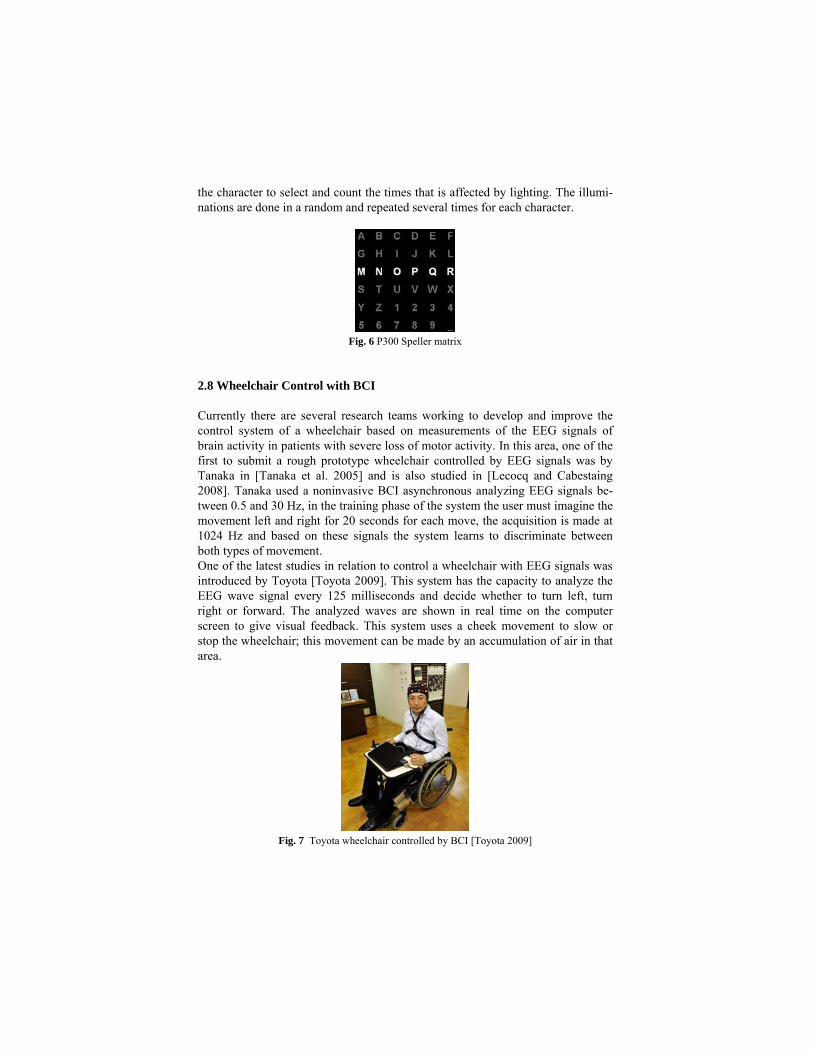
the character to select and count the times that is affected by lighting. The illumi-nations are done in a random and repeated several times for each character.
Fig. 6 P300 Speller matrix
2.8 Wheelchair Control with BCI
Currently there are several research teams working to develop and improve the control system of a wheelchair based on measurements of the EEG signals of brain activity in patients with severe loss of motor activity. In this area, one of the first to submit a rough prototype wheelchair controlled by EEG signals was by Tanaka in [Tanaka et al. 2005] and is also studied in [Lecocq and Cabestaing 2008]. Tanaka used a noninvasive BCI asynchronous analyzing EEG signals be-tween 0.5 and 30 Hz, in the training phase of the system the user must imagine the movement left and right for 20 seconds for each move, the acquisition is made at 1024 Hz and based on these signals the system learns to discriminate between both types of movement. One of the latest studies in relation to control a wheelchair with EEG signals was introduced by Toyota [Toyota 2009]. This system has the capacity to analyze the EEG wave signal every 125 milliseconds and decide whether to turn left, turn right or forward. The analyzed waves are shown in real time on the computer screen to give visual feedback. This system uses a cheek movement to slow or stop the wheelchair; this movement can be made by an accumulation of air in that area.
Fig. 7 Toyota wheelchair controlled by BCI [Toyota 2009]

Another work with wheelchair control based on EEG is done by the project OpenViBE [Lecuyer 2007] and [renard and Delannoy 2009]. OpenViBE is a free platform to develop BCI applications, within these different applications was a control of a wheelchair, for which uses electrodes at positions C3 and C4 of the in-ternational position of electrodes 10/20 to capture the signals of intention to move left or right hand and thus represent the rotation the wheelchair to the right or left respectively, for EEG signals representing the movement of feet, an electrode is placed in the front and thus represents the advancement of the wheelchair. In a first moment is perceived to be very difficult to handle the wheelchair with these premises, so in a second experiment using the signal from the feet to select from several target destinations, so once you select your destination, as Wheelchair uses other algorithms to get to your chosen destination and progress.
3 Development of the Work
Fig. 8 Block Diagram
3.1 Data Acquisition
For the data acquisition, electrodes of 8 mm of Ag/AgCl fixed on C3 and C4 of the international system of positioning 10/20 were used. Signal amplification was made through amplifier EEG of 8-channel model Procomp Infinity. The sampling frequency is of 256 Hz. A digital band-pass filter has been implemented between 0.5 and 30 Hz in real time to especially eliminate the noise originating from the mains and other sources.

. Fig. 9 Electrodes
Fig. 10 Amplifier Procomp Infinity
3.2 Features Extraction
The stage of extraction of characteristics is probably the most critical step in the processing of signal EEG, with a view to maximizing the potential success of the classification stage as well as the global yield of the system. A second objective of the stage is to compress the data without loss of excellent information through the process of classification so that it can operate in real-time. The rhythm μ, which corresponds to an oscillation of signal EEG between the 8 and 13 Hz, is caught in the sensorimotor zone located in the central hairy region. This rhythm, present in most adults, has particularity to present attenuation in its amplitude when some types of movement are performed, or what is more important when the intention is had to realize some movement, or simply imagining movements of the extremi-ties, as shown in Figures 11 to 14.
Fig. 11 Cerebral activity during the imagination of movements of the right hand and left hand

Fig. 12 Difference in the frequency band alpha between movement and rest
It is possible to stress that movements of the right hand produce a variation in the activity of the left part of the brain and vice versa.
Fig. 13 Difference in the frequency band alpha between movement of the right hand and left
hand in the electrode of the position C3
Fig. 14 Difference in the frequency band alpha between movement of the right hand and left
hand in the electrode of the position C4

To quantify these characteristics (visibly observable) and then apply the classification methods, we use two different sets of characteristics: The first is a set of autoregressive parameters that represent spectral analysis, and the second will be to obtain spectral energy in Mu and Beta band for each electrode.
3.3 Autoregressive Adaptative Parameters (AAR)
To represent the characteristics previously described in numbers that allow us to implement a sort algorithm because we used autoregressive adaptive parameters that allows us to represent the frequency response of the signal as shown in Figure 15. A model AAR of order p is written as follows:
)()1(*)(
)()(*)(...)1(*)()( 1
txtYta
txptytatytatyT
p
+−=
+−++−=
(1)
The difference with the stationary molding autoregressive (AR) is that parameters AAR vary with them; the prediction of the error is calculated as follows:
)1(*)1()()( −−−= tYtâtyte T (2)
For parameter calculation, we used the method of least mean squares (LMS), which is given by the following equation:
)1(*)(*)/()1()( −+−= tYteMSYUCtâtâ (3) where:
0 10 20 30 40 50 60 700
0.005
0.01
0.015
0.02
0.025
0.03
0.035
0.04
0 10 20 30 40 50 60 700
5
10
15
20
25
Fig. 15 Comparison of frequency response with the FFT and parameter AAR
With 6 parameters AAR at each electrode, there are a total of 12 characteristics.
∑=
=→
=→N
ttY
NVarianceSignalMSY
tCoefficienUpdateUC
1
210055.0

3.4 Spectral Energy in Mu and Beta Band (PST)
In this case we will calculate the spectral energy in the Mu band (8-13 Hz) and Beta band (17-24 Hz) for each electrode (positions C3 and C4) which is why we will have in total a set of 4 features. The analysis is performed continuously in each moment of time as shown in Figure 16, we take a window of 1 second, this window will move in every moment of time in each window the work being done is to filter the signal first with a bandpass filter of 8-13 Hz and then calculate the spectral energy in the band Mu using the equation (4):
∑=
=N
ttY
NPST
1
21 (4)
Where: PST = Spectral energy. N = 256, as the windows is 1 sec. and de sampling frequency is 256 Hz Then we filter the window with a bandpass filter between 17 and 24 Hz to calculate the energy in the Beta band.
0 1 2 3 4 5 6 7 8 9-0.4
-0.3
-0.2
-0.1
0
0.1
0.2
0.3
Fig. 16 Window signal to obtain the spectral energy in the Mu and Beta Band
3.5 Classification
The phase of classification is the final task of the process. The entrance to the sort algorithm is the set of characteristics extracted in the previous stage, and the exit is an indication of the mental state of the user. In this case, we are working with two states: left and right. For the present work, two methods of classification were developed: linear discri-minating analysis and neuronal network. Both methods give similar results of a constant weight vectors; this way, the activation function would be as follows:
cteWXAC
ctewxAC ii
+=
+=∑*
*
(4)

4 Test Process
4.1 Fixation of Electrodes
Bipolar electrodes are used; each electrode is placed at 2.5 centimeters toward the back and at positions C3 and C4, as shown in Figures 17 and 18.
Fig. 17 Fixation of the bipolar electrodes in C3 and C4
Fig. 18 Photographs with the fixed electrodes
To fix the electrodes, gel and conductive grease were used.
Fig. 19 Gel and conductive grease
4.2 Acquisition of the Signal and Training
Each of the tests lasts for only 9 seconds, and during the training process, we per-formed 60 tests. The test begins at rest, and after 3 seconds, the system randomly chooses a value to send to the right or left signal. This is why the person will have

the 6-second rest to imagine the movement specified (for better understanding, please refer to Figure 20).
Fig. 20 Composition of the 9 seconds of the test [Schlogl et al. 2003]
Fig. 21 Photographs during the process of acquisition of EEG signals
For the training, two stages were performed. First is offline training, where there is no feedback; this serves to register and keep the data for analysis. Second is online training where feedback regarding function to the preliminary results of the offline analysis exists; this training serves so that the user can learn to control the cerebral activity more effectively. In Figures 22 and 23, we can observe the forms imple-mented for each of the trainings.
Fig. 22 Interface for offline training
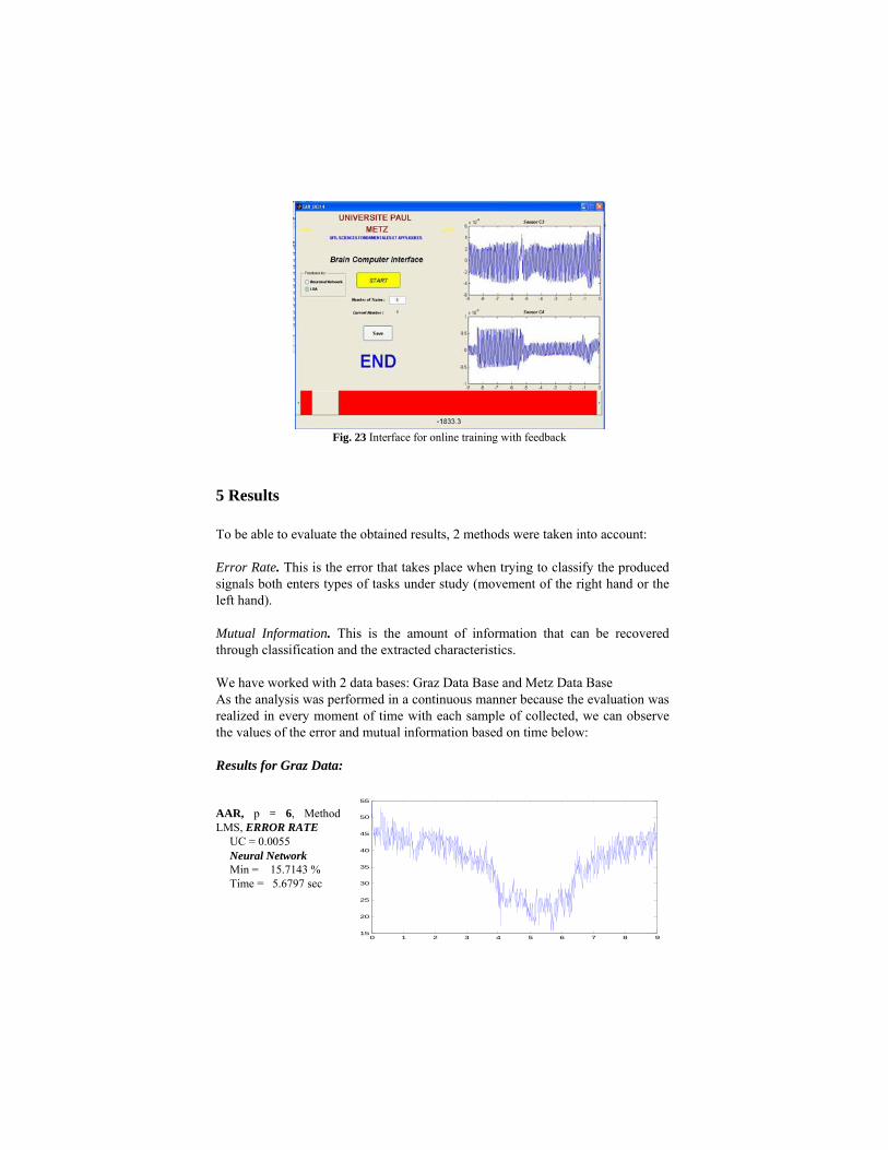
Fig. 23 Interface for online training with feedback
5 Results
To be able to evaluate the obtained results, 2 methods were taken into account:
Error Rate. This is the error that takes place when trying to classify the produced signals both enters types of tasks under study (movement of the right hand or the left hand).
Mutual Information. This is the amount of information that can be recovered through classification and the extracted characteristics.
We have worked with 2 data bases: Graz Data Base and Metz Data Base As the analysis was performed in a continuous manner because the evaluation was realized in every moment of time with each sample of collected, we can observe the values of the error and mutual information based on time below: Results for Graz Data: AAR, p = 6, Method LMS, ERROR RATE
UC = 0.0055 Neural Network Min = 15.7143 % Time = 5.6797 sec
0 1 2 3 4 5 6 7 8 915
20
25
30
35
40
45
50
55

AAR, p = 6, Method LMS, ERROR RATE
UC = 0.0055 LDA Min = 12.8571 % Time = 5.2969 sec
AAR, p = 6, Method LMS, MI
UC = 0.0055 Neural Network Max = 0.4583 Time = 5.7422 sec
AAR, p = 6, Method LMS, MI
UC = 0.0055 LDA Max = 0.5328 Time = 5.1563 sec
The difference between the spectral energy of the band can be graphical alpha (8 – 13 Hz) of C3 and C4 when types of movement both take place. Furthermore, we can graph the function of the resulting activation of the classification method that is obtained when the movements is either left or right. Both graphs are based on time because of the continuous analysis that I am realized in every moment of time, as shown in Figures 24 and 25. Using the spectral energy (PST) we have the following results:
Method PST, MUTUAL INFORMATION
Neural Network Máx = 0.4567 Time = 5.0469 sec Files TRAIN
0 1 2 3 4 5 6 7 8 9-0.1
0
0.1
0.2
0.3
0.4
0.5
0.6
0 1 2 3 4 5 6 7 8 90
5
10
15
20
25
30
35
40
45
0 1 2 3 4 5 6 7 8 9-0.2
-0.1
0
0.1
0.2
0.3
0.4
0.5
0.6
0.7
0 1 2 3 4 5 6 7 8 9-0.2
-0.1
0
0.1
0.2
0.3
0.4
0.5
0.6
0.7
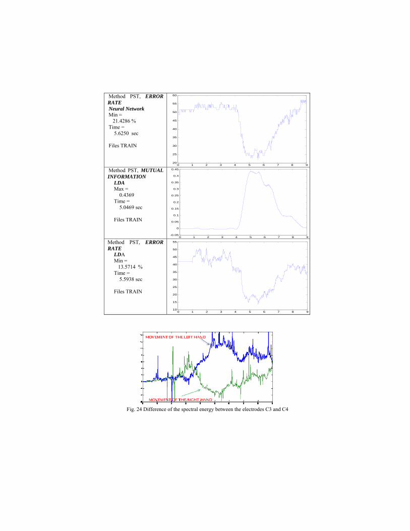
Method PST, ERROR RATE Neural Network Min = 21.4286 % Time = 5.6250 sec Files TRAIN
0 1 2 3 4 5 6 7 8 920
25
30
35
40
45
50
55
60
Method PST, MUTUAL INFORMATION
LDA Max = 0.4369 Time = 5.0469 sec Files TRAIN
0 1 2 3 4 5 6 7 8 9-0.05
0
0.05
0.1
0.15
0.2
0.25
0.3
0.35
0.4
0.45
Method PST, ERROR RATE
LDA Min = 13.5714 % Time = 5.5938 sec Files TRAIN
0 1 2 3 4 5 6 7 8 910
15
20
25
30
35
40
45
50
55
Fig. 24 Difference of the spectral energy between the electrodes C3 and C4

Fig. 25 Graph of the function of the activation for movements of the right hand and left hand
Through these graphs, it can be observed that the classes under study are separa-ble.
After making this first step OFFLINE training and have analyzed the data, we turn to step ONLINE training using the vector and the constant found in the previous step based on the results shown. As a result we obtained the following confusion matrix
Confusion Matrix Classe Right Left TOTAL Right 59 11 70 (*)
Left 8 62 70 (+) % Right 84.29 15.71 100
Left 11.43 88.57 100
Results for Metz Data:
Method AAR, MUTUAL INFORMATION
Neural Network Máx = 4.5234 Time = 0.5751 sec Files TRAIN 0 1 2 3 4 5 6 7 8 9
-0.2
0
0.2
0.4
0.6
0.8
1
1.2
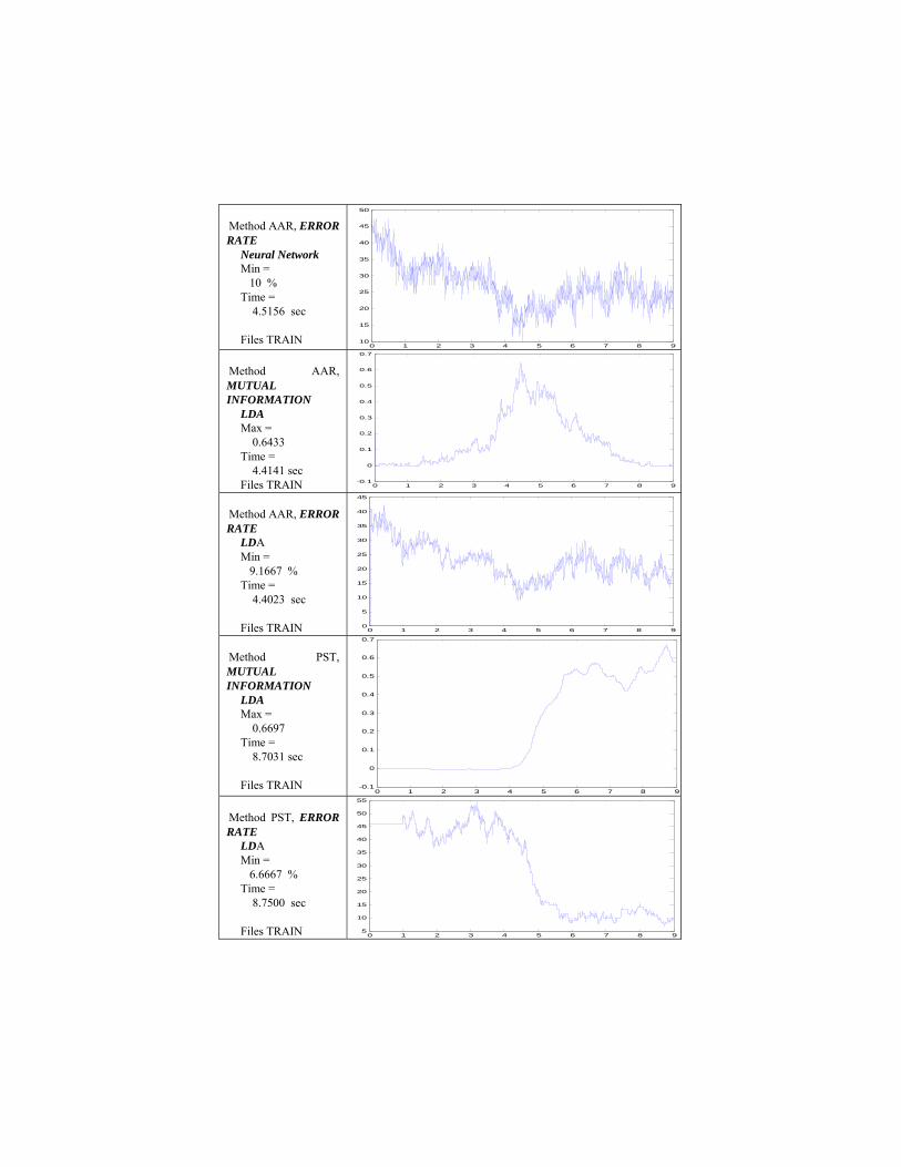
Method AAR, ERROR RATE
Neural Network Min = 10 % Time = 4.5156 sec Files TRAIN
0 1 2 3 4 5 6 7 8 910
15
20
25
30
35
40
45
50
Method AAR, MUTUAL INFORMATION
LDA Max = 0.6433 Time = 4.4141 sec Files TRAIN 0 1 2 3 4 5 6 7 8 9
-0.1
0
0.1
0.2
0.3
0.4
0.5
0.6
0.7
Method AAR, ERROR RATE
LDA Min = 9.1667 % Time = 4.4023 sec Files TRAIN 0 1 2 3 4 5 6 7 8 9
0
5
10
15
20
25
30
35
40
45
Method PST, MUTUAL INFORMATION
LDA Max = 0.6697 Time = 8.7031 sec Files TRAIN
0 1 2 3 4 5 6 7 8 9-0.1
0
0.1
0.2
0.3
0.4
0.5
0.6
0.7
Method PST, ERROR RATE
LDA Min = 6.6667 % Time = 8.7500 sec Files TRAIN 0 1 2 3 4 5 6 7 8 9
5
10
15
20
25
30
35
40
45
50
55

Confusion Matrix Classe Right Left TOTAL Right 26 3 29 (*)
Left 1 30 31 (+) % Right 89.66 10.34 100
Left 3.23 96.77 100
6 Discussion and Conclusions
We can observe that in the results obtained on data published by the University of Graz, the use of autoregressive parameters provides better results than the spectral energies, whereas the reverse is true for the our Metz data. This may be due to the fact that data published by the University of Graz match better filtered signals, and therefore the AAR model which reflects all the spectrum is more significant than the energies of the Mu and Beta band. Moreover, one can observe in the data provided from the University of Graz and in our database, there is a smaller error when trying to classify a signal representing a movement of left hand that represents a movement of the right hand this may be caused likely that the system assumes a state of rest as a movement to the left hand and thereby the left hand classification would be more decisive. We conducted trials with much hand movement and with only the imagination of movements, the best results are obtained when the user only imagine the movement, this may be because there is a greater concentration only when we imagine the movement while it is possible to achieve movements automatically without thinking. Through this article we provide the basis and foundation for developing a brain-computer interface, showing the different steps to implement a BCI, the different stages of processing and analyzing the different techniques currently used. The most important aspects to be taken into account in order to have good results: A good fixation of the electrodes on the scalp, which required a measure of the impedance of the electrodes on the scalp, which should be less than 5 K ohms. It is always necessary prior training stage. However there are investigations that seek to perform discrimination tasks without training, but the results are not encourag-ing. Each person has a different way of managing their brain activity. To ensure good training, each individual or user needs to perform at least 60 tests. The analysis has been performed in a continuous manner during the 9 seconds of each test, and the best results—with minimum error and maximum value for mu-tual information—are found between the fifth and sixth seconds The results so far are very encouraging, in some cases reaching rates of 93% ef-fective, but even more must be done about it because it is necessary to increase the number of free degrees, a better definition of states, speed in the interpretation, to be able to have more complex applications

References
[Roman-Gonzalez 2010 (1)] A. Roman Gonzalez, (2010), System of Communication and Control based on the Thought. IEEE In-ternational Conference on Human System Interaction – HSI’10, Poland, pp. 275-280. [Roman-Gonzalez 2010 (2)] A. Roman Gonzalez, (2010), Communication Technologies Based on Brain Activity. World Congress in Computer Science, Computer Engineering and Applied Computing –WORLDCOMP 2010, Las Ve-gas, Nevada, USA. [Hoffmann et al.] U. Hoffmann, J. Vesin, T. Ebrahimi, Recent Advances in Brain-Computer Interfaces. Ecole Polytech-nique Federale de Laussanne (EPFL), Switzerland. [Wolpaw et al. 2002] J. R. Wolpaw, N. Birbaumer, D. J. McFarland, G. Pfurtscheller, T. M. Vaughan, (2002), Brain-Computer Interfaces for Communication and Control. Clinical Neurophysiology 113 – ELSEIVER, pp. 767-791. [Lecocp and Cabestaing 2008] C. Lecocq, F. Cabestaing, (2008), Les Interfaces Cerveau-Machine pour la Palliation du Handicap Mo-tor Severe. LAGIS – Laboratoire d’Automatique, Génie Informatique & Signal, Université des Sciences et Technologie de Lille. [Lee and Tan 2006] J. C. Lee, D. S. Tan, (2006), Using a Low-Cost Electroencephalograph for Task Classification in HCI Research. UIST, Montreux Switzerland. [Kuo-Kai et al. 2010] S. Kuo-Kai, L. Po-Lei, L. Ming-Huan, L. Ming-Hong, L. Ren-Jie, Ch. Yun-Jen, (2010), Development of a Low-Cost FPGA-Based SSVEP BCI Multimedia Control System. IEEE Transaction on Biomedi-cal Circuits and Systems, vol. 4, N° 2, pp. 125-132. [Kirby] M. Kirby, Some Mathematical Ideas for Attacking the Brain Computer Interface Problem. Departe-ment of Mathematics, Colorado State University. [Gollee et al. 2010] H. Gollee, I. Volosyak, A. J. McLachlan, K. J. Hunt, A. Graser, (2010), An SSVEP Based Brain-Computer Interface for the Control of Functional Electrical Stimulation. IEEE Transaction on Biomed-ical Engineering. [Trejo et al. 2006] L. J. Trejo, R. Rosipal, B. Matthews, (2006), Brain-Computer Interfaces for 1-D and 2-D Cursor Con-trol: Design Using Volitional Control of the EEG Spectrum or Steady-State Visual Evoked Potentials. IEEE Transaction on Neural Systems and Rehabilitation Engineering, vol. 14, N° 2, pp. 225-229. [Solis-Escalante and Pfurtscheller 2009] T. Solis Escalante, G. Pfurtscheller, (2009), Brain Switch Asincrónico Basado en Ritmos Sensorimoto-res. Seminario de Bioingeniería Elche. [Alarid-Escudero] F. Alarid-Escudero, T. Solis-Escalante, E. Melgar, R. Valdes-Cristerna, O. Yañez-Suarez, Registro de Señales de EEG para Aplicaciones de Interfaz Cerebro Computadora (ICC) Basado en Potenciales Evocados Visuales de Estado Estacionario (PEVEE). Universidad Autónoma Metropolitana, México.

[Pfurtscheller and Lopes-da-Silva 1999] G. Pfurtscheller, F. H. Lopes da Silva, (1999), Event-related EEG/MEG Synchronization and Desyn-chronization: Basic Principles. Clinical Neurophysiology 110, 1842-1857, ELSEIVER. [Kamousi et al. 2005] B. Kamousi, Z. Liu, B. He, (2005), Classification of Motor Imagery Tasks for Brain-Computer Inter-face Applications by Means of Two Equivalent Dipoles Analysis. IEEE Transaction on Neural Sys-tems and Rehabilitation Engineering, vol. 13, N° 2, pp. 166-171. [Kachenoura et al. 2008] A. Kachenoura, L. Albera, L. Senhadji, P. Comon, (2008), ICA: A Potential Tool for BCI System. IEEE Signal Processing Magazine, 25(1): 57-88. [Faradji et al. 2009] F. Faradji, R. K. Ward, G. E. Birch, (2009), A Brain-Computer Interface Based on Mental Task with Zero False Activation Rate. IEEE EMBS Conference on Neural Engineering, Turkey. [Tavakolian et al.] K. Tavakolian, F. Vasefi, K. Naziripour, S. Rezaei, Mental Task Classification for Brain Computer In-terface Applications. Canadian Student Conference on Biomedical Computing. [Milan and Carmena 2010] J. Milan, J. M. Carmena, (2010), Invasive or noninvasive: understanding brain–machine interface tech-nology. IEEE Engineering in Medicine and Biology Magazine, pp. 16-22. [Lecuyer 2007] A. Lecuyer, (2007), Interfaces Cerveau-Machine: Avancees Recentes et Perspectives a travers le Projet Open-ViBE. Journée IRISATECH. [Farwell and Donchin 1988] L. A. Farwell and E. Donchin, (1988), Talking off the top of your head: A mental prosthesis utilizing event-related brain potentials. Electroencephalography and Clinical Neurophysiology, vol. 70, pp. 510-513. [Garcia-Cossio and Gentiletti 2008] E. Garcia Cossio, G. Gabriel Gentiletti, (2008), Interfaz Cerebro Computadora (ICC) Basada en el Po-tencial Relacionado con Eventos P300: Analisis del Efecto de la Dimension de la Matriz de Estimula-cion sobre su Desempeño. Revista Ingenieria Biomedica, vol. 2, N° 4, pp. 26-33. [Ma et al. 2010] Z. Ma, R. Millar, R. Hiromoto, A. Krings, (2010), Logics in Animal Cognition: Are They Important to Brain Computer Interfaces (BCI) And Aerospace Mission. IEEE AC. [Toyota 2009] Toyota Motor Corporation, (2009), Real-time control of wheelchairs with brain waves. RIKEN. [Renard and Delannoy 2009] Y. Renard, V. Delannoy, (2009), OpenViBE Platform Development Training Course. INRIA. [Tanaka et al. 2005] K. Tanaka, K. Matsunaga, H. Wang, (2005), Electroencephalogram-based control of an electric wheel-chair. IEEE Transaction on Robotics, vol. 21, N° 4, pp. 762-766.