Embed Size (px)
Citation preview

Effects of Gallium Doping in Garnet-Type Li7La3Zr2O12 SolidElectrolytesRandy Jalem,†,‡ M.J.D. Rushton,§ William Manalastas, Jr.,∥ Masanobu Nakayama,†,‡,# Toshihiro Kasuga,⊥
John A. Kilner,§,∥ and Robin W. Grimes*,§
†Unit of Elements Strategy Initiative for Catalysts & Batteries (ESICB), Kyoto University, Katsura, Saikyo-ku, Kyoto 615-8520, Japan‡Department of Materials Science and Engineering and ⊥Department of Frontier Materials, Nagoya Institute of Technology, Gokiso,Showa, Nagoya, Aichi 466-8555, Japan§Department of Materials, Imperial College London, Prince Consort Road, London SW7 2AZ, United Kingdom∥CIC Energigune, Parque Tecnologico, C/Albert Einstein 48, CP 01510 Minano, Alava, Spain#Japan Science and Technology Agency, PRESTO, 4-1-8 Honcho Kawaguchi, Saitama 332-0012, Japan
*S Supporting Information
ABSTRACT: Garnet-type Li7La3Zr2O12 (LLZrO) is a candi-date solid electrolyte material that is now being intensivelyoptimized for application in commercially competitive solidstate Li+ ion batteries. In this study we investigate, by force-field-based simulations, the effects of Ga3+ doping in LLZrO.We confirm the stabilizing effect of Ga3+ on the cubic phase.We also determine that Ga3+ addition does not lead to anyappreciable structural distortion. Li site connectivity is notsignificantly deteriorated by the Ga3+ addition (>90%connectivity retained up to x = 0.30 in Li7−3xGaxLa3Zr2O12).Interestingly, two compositional regions are predicted for bulkLi+ ion conductivity in the cubic phase: (i) a decreasing trend for 0 ≤ x ≤ 0.10 and (ii) a relatively flat trend for 0.10 < x ≤ 0.30.This conductivity behavior is explained by combining analyses using percolation theory, van Hove space time correlation, theradial distribution function, and trajectory density.
■ INTRODUCTION
Solid electrolytes with high lithium ionic conductivity are nowbeing actively investigated for application in commerciallycompetitive all-solid-state rechargeable lithium-ion batteries.Among them, Li-based garnet oxides have shown promise formeeting the much needed safety and reliability requirements oftoday’s commercial lithium ion batteries.1−7 One of the garnetcompositions being considered is the cubic Li7La3Zr2O12(LLZrO), this is due to its stability with elemental lithiumand a total conductivity on the order of 10−4 S/cm.2 Itsstructure is usually defined in the Ia3 d space group with Lications partiallly occupying 24d tetrahedral (Td) and 48g/96hoctahedral (Oh) sites, La cations fully occupying 24cdodecahedral sites, Zr cations fully occupying 16a octahedralsites, and O anions fully occupying the 96h sites (see Figure 1).However, a more stable tetragonal symmetry (I41/acd) has alsobeen reported to exist at room temperature, with Li ordering inthree crystallographic sites: one at the 8a site, which forms asubset of the cubic garnet 24d site, and the other two highlydistorted 16f and 32g sites which, when combined, areequivalent to the cubic garnet 48g/96h sites.8,9 This orderingis responsible for the low bulk Li+ ion conductivity measuredfor tetragonal LLZrO, a value on the order of 1 × 10⁻⁶ S/cm atroom tempertaure.8
Received: December 9, 2014Revised: March 12, 2015Published: April 6, 2015
Figure 1. (a) Crystal structure of garnet-type cubic Li7La3Zr2O12. Liatoms are shown as green/white spheres (to indicate partialoccupancy). La dodecahedra and Zr octahedra are shown in orangeand blue, respectively. The Li pathway segment is highlighted in theright image by the linkage of 24d (Td) and 48g/96h (Oh) sites.
Article
pubs.acs.org/cm
© 2015 American Chemical Society 2821 DOI: 10.1021/cm5045122Chem. Mater. 2015, 27, 2821−2831
This is an open access article published under a Creative Commons Attribution (CC-BY)License, which permits unrestricted use, distribution and reproduction in any medium,provided the author and source are cited.

Conductivity in LLZrO is known to vary depending on thesynthesis route employed, with methods that are carried out atlow10−14 and high temperatures15−24 yielding different values.Optimization efforts have focused on obtaining the cubic phaseby promoting disorder across the Li sublattice; dopantincorporation is typically employed, targeting the frameworkcation sites (i.e., La and Zr). Some notable improvements werereported for Te-doped LLZrO (1.02 × 10⁻³ S/cm),15 Ta-doped LLZrO (1.0 × 10⁻³ S/cm),16−19 Nb-doped LLZrO (8.0× 10⁻⁴ S/cm),20 Sb-doped LLZrO (7.7 × 10⁻⁴ S/cm),21 andSr-doped LLZrO (5.0 × 10⁻⁴ S/cm).22 Simultaneoussubstitution was also explored in the series Li7+x−y(La3−xAx)-(Zr2−yNby)O12 (where A is an alkali earth metal) and hasshown that an optimum lattice parameter at a constant lithiumcontent of 6.5 per formula unit (p.f.u.) can be obtained.23
On the other hand, several simulation studies for LLZrOhave been made almost hand in hand with experiments,focusing on understanding Li+ ion diffusion mechanisms, phasetransition, and stability. For example, in our previous densityfunctional theory (DFT) molecular dynamics (MD) calcu-lations, we found that the complex mechanism for self-diffusionof Li+ ions in LLZrO proceeds in a cooperative manner and isgoverned by two crucial features: (i) the restriction imposed foroccupied site-to-site interatomic separation and (ii) theapparent unstable residence of the Li+ ion at the Td site dueto local Li−Li repulsion effect.25 Meier et al. further providedinformation to establish the difference between the Li+ iondiffusion mechanism of the tetragonal and cubic phase throughDFT-based MD and metadynamics simulations; the former hasa fully collective nature or synchronous motion while the latterhas an asynchronous motion governed by single-ion jumps andinduced collective motion.26 In another simulation usingclassical MD, with a BV-based Morse-type force field, Adamset al. predicted that for the garnet Li7−xLa3(Zr2−xMx)O12 system(x = 0, 0.25; M = Ta5+, Nb5+): (i) the lithium distribution justabove the cubic phase transition closely resembles that in thetetragonal phase and that (ii) pentavalent doping can enhanceionic conductivity by increasing the vacancy concentration andby reducing local Li ordering.27 Wang et al. discovered throughstatic energy minimization with Buckingham potentials, that theshape of energy probability distribution, can aid in under-s t and ing l i th ium di sorder/order effec t s in theLi7−xLa3Zr2−xTaxO12 (x = 0−2) series.28 Miara et al.investigated the effect of Rb and Ta doping on the ionicconductivity and stability of the garnet Li7+2x−y(La3−xRbx)-(Zr2−yTay)O12 (0 ≤ x ≤ 0.375, 0 ≤ y ≤1) using ab initio-basedcalculations and concluded that (i) Rb or Ta doping does notchange the topology of the migration pathways significantly,but instead acts primarily to change the lithium concentration,and that (ii) doping with larger cations will not provide asignificant enhancement in performance.29 Bernstein et al. hasrevealed by DFT and variable cell shape MD simulations thatthe strong dependence of the tetragonal phase stability on thesimultaneous ordering of the Li+ ions on the Li sublattice and avolume-preserving tetragonal distortion that relieves internalstructural strain.30 Nakayama et al. used DFT to investigate theelectrochemical stability of different garnet compositions in thecompositional range LixLa3M2O12 (where x = 5 or 7; M = Ti,Zr, Nb, Ta, Sb, Bi) against Li metal and found that theelectrochemical stability is strongly dependent on the effectivenuclear charge of the M cation.31 Predictions made by Santoshet al. using a DFT approach have indicated that the Li+ vacancydefects are thermodynamically more favorable than interstitial
Li+ defects.32 Overall, these efforts have significantly con-tributed to a better understanding of the measured propertiesof LLZrO-based materials.Most doping strategies have been geared toward tuning
conductivity without obstructing Li pathways, as highlightedabove. However, substitution in LLZrO had also been carriedout on the Li sublattice itself, directly impeding the conductionpath of Li+ ions. The most studied example of this is theintentional or unintentional chemical substitution of Li+ byAl3+.33−39 Two Li site vacancies are created for every additionof Al3+ and this is made possible primarily by the small ionicradius of Al3+ in the two Li coordination environments (rAl3+ =0.39 Å vs rLi+ = 0.59 Å for tetrahedral coordination and rAl3+ =0.535 Å vs rLi+ = 0.76 Å for octahedral coordination). However,to date, the site preference for Al3+ has been ambiguous.Neutron diffraction data measurement made by Li et al.suggested an octahedral (48g)-site occupancy35 but Wang etal.36 and Buschmann et al.37 concluded, based on their27AlMAS NMR spectroscopy results, that Al sits mostly in the 24dtetrahedral site. Geiger et al.38 added that, according totheir27Al MAS NMR spectral analysis, Al3+ may also occupy adistorted site with 5-fold coordination which is presumably atthe octahedral site; one of the two main resonances they found,which is assigned to an octahedral environment for Al3+, wasattributed to the LaAlO3 impurity phase. Similarly, Retten-wander et al. showed, by combining27Al NMR data and DFTcalculation, that Al3+ could sit, not only in a 24d site but also ina distorted 4-fold coordinated 96h site and even a 48g site withalmost regular octahedral coordination; they also suggested thatoctahedral occupancy for Al3+ may be stabilized depending on anumber of factors such as dopant concentration, sinteringtemperature and time, heating rate, grain sizes, startingmaterials, etc.39 Duvel et al. prepared Al-doped LLZrO samplesby a mechanochemical route and discovered that withincreasing Al content, Al ions can also substitute at non-Lication sites, leading to the formation of La- and Zr-deficientLLZrO.40 Huang et al. indicated a similar effect for Ge-dopedLLZrO, according to a comparison of their experimental andsimulated XANES spectra.41
Recently, Ga-doped cubic LLZrO was successfully preparedby standard solid state synthesis42−44 and a low-temperature solgel approach.45 Similar with Al3+, the ionic radius of Ga3+ (0.47and 0.62 Å for tetrahedral and octahedral coordination,respectively) is also comparable with that of Li+. This systemhas demonstrated comparable and even better structural andtransport properties than the Al case.42,43 In common with Al-doped LLZrO, the Ga distribution in the LLZrO framework isalso difficult to ascertain. 71Ga NMR spectroscopy conductedby Howard et al. for Li5.5Ga0.5La3Zr2O12 (1 × 10⁻⁴ S/cm)revealed a single broad peak with a chemical shift of ∼221 ppmwhich was assigned to Ga3+ at tetrahedral sites.42 Bernuy-Lopezet al. came to the same conclusion via their 71Ga NMRspectrum for Li5.5Ga0.15La3Zr2O12 which was sintered in a dryO2 atm (1.3 × 10⁻³ S/cm), from which a chemical shift wasobtained with a value of 207 ± 10 ppm.43 On the other hand, inthe range 0.08 ≤ x ≤ 0.84 for Li7−3xGaxLa3Zr2O12, Retten-wander et al. suggested, based on the relatively large NMRasymmetry parameter that they derived, ηQ = 0.46(3), that Ga3+
mainly occupies a distorted 4-fold coordinated environmentcorresponding to the general 96h octahedral site.44 Allen et al.18
also proposed the 96h octahedral site occupancy, following thework of Geller et al.46 who reported that Ga3+ preferred 6-foldcoordination in garnet.
Chemistry of Materials Article
DOI: 10.1021/cm5045122Chem. Mater. 2015, 27, 2821−2831
2822
Until now, except for the stabilizing effect on the cubic phase,there is no clear understanding of how foreign ionincorporation in the Li sublattice affects the structure, pathtopology and Li+ ion dynamics of doped LLZrO. This is animportant issue since the blocking effect by aliovalent dopantscan progressively reduce path connectivity but conversely mayalso promote Li disordering for cubic phase stabilization due tothe variation in the number of Li vacancies (Figure 1 shows thelinkage of Td and Oh sites). In this study, we investigated theeffects of Ga doping in the solid solution seriesLi7−3xGaxLa3Zr2O12 (0 ≤ x ≤ 0.3) using atomistic simulationswith Buckingham-type interatomic potentials. Our results offerpractical insights beneficial to experimentalists, especially whenformulating strategies for conductivity optimization in dopedLLZrO materials.
■ COMPUTATIONAL DETAILSDerivation of Interatomic Potentials. The crystal lattice was
modeled using a classical Born description.47 The total energy of thesystem was calculated by summing contributions from long-rangeelectrostatic, short-range repulsive and van der Waals interactions. Thelong-range electrostatic interaction is given by Coulomb’s law
π=
ϵU
q q
r4i j
ijij
0 (1)
where qi and qj are the charges of ions i and j, respectively, ϵ0 is the freespace permittivity, and rij is the distance between the ions. Uij wasevaluated via the Ewald approach.48 Nonformal charges were used,based on a partially ionic model; the ions’ fractional effective charges(qeff) were calculated from the product of their nominal charge (qnom)and a defined ionicity parameter ζ, namely
ζ=q q( )( )eff nom (2)
where ζ < 1. These effective charges are proportional to their nominalcharges to ensure charge neutrality. For the short-range interactions,Φij, the Buckingham potential form was used49
ρΦ =
−−
⎛⎝⎜⎜
⎞⎠⎟⎟r A
r C
r( ) expij ij ij
ij
ij
ij
ij6
(3)
where Aij, ρij, and Cij are empirically derived parameters for interactingions i and j. The cutoff distance, beyond which short-range interactionsare considered negligible, was set to 10.5 Å. Using ζ = 0.70, thepotential parameters (A, ρ, and C) were fitted against experimentallattice constants of several relevant oxides. Essentially, an error-basedobjective function, Efit, is minimized during the fitting procedure, asgiven by
∑= −=
E x xw ( )i
N
i ifit1
iexpt calcd 2
expt
(4)
where Nexpt is the number of experimental parameters used to evaluatethe fit, wi is the weighting factor (set to 1 for all parameters for equalweighting), and xi
expt and xicalcd are the experimental and calculated
parameter values, respectively. Efit was minimized using the Nelder−Mead simplex algorithm.50 The constant-pressure energy minimizationroutine, in which the dimensions of the simulation box are relaxedtogether with atom positions, was performed with the GULP codeusing the Broyden−Fletcher−Goldfarb−Shanno algorithm.51
Li−Ga Vacancy Configuration Sampling. In this study, a 3 × 3× 3 supercell (containing 1944 available Li sites, 648 La atoms, 432 Zratoms, and 2592 O atoms). For simplicity, the tetrahedral 24d andoctahedral 48g/96h site cage were labeled as Td and Oh site,respectively. There exists an enormous number of conceivablearrangements for the Li, Li vacancy, and Ga species within the Lisublattice of a basic cubic (I) garnet structure, this increases evenfurther with increasing model cell size. For practical reasons, a random
sampling approach for the Li−Ga vacancy arrangements was used, thenumber of Li and Ga atoms were adjusted according to stoichiometryand with Ga content x varied in the range 0 ≤ x ≤ 0.30. At each x, atotal of 16 000 random structures spanning from all-Td to all-Oh Gaoccupancy were evaluated by a two-step screening procedure. In thefirst step, electrostatic/Coulomb energies were calculated.48 In thesecond step, the lowest Coulomb energy structures for each discreteGa occupancy ratio, denoted by Td/(Td+Oh), from the first step wereoptimized using the fitted Buckingham potentials.
Molecular Dynamics Simulation. All MD simulations were runwith the DL_POLY code52 with a time step of 1 fs. Three statisticalmechanical ensembles were used, namely: (i) the microcanonicalensemble which maintains constant number of particles, volume, andenergy (NVE), (ii) the canonical ensemble with constant number ofparticles, volume, and temperature (NVT), and (iii) the isothermal−isobaric ensemble with constant number of particles, pressure, andtemperature (NPT). To ensure that the average temperature, pressure,and/or stress tensor are maintained close to the target conditions, theNose-Hoover thermostat (for the NVT MD run) and barostat (for theNPT MD run) were used, with 0.8 and 1.2 ps as relaxation times,respectively.53 A heating schedule was followed for MD productionsampling: (i) 10 ps NVE MD run at 300 K with 5 ps equilibration, (ii)temperature ramping in the NPT ensemble from 300 K up to thetarget temperature incrementing at a rate of 100 K per 30 ps, and (iii)500 ps NVT MD run at the target temperature. For the thermalexpansion/contraction analysis, a similar heating schedule wasfollowed but instead the run was performed in the NPT ensembleat a rate of 30 ps per 50 K step, with 100 ps sampling at the targettemperature. Target pressure for constant pressure ensembles were setto 1 atm. Trajectory collection was carried out every 10 MD steps.
■ RESULTS AND DISCUSSIONConfiguration Sampling. Incorporation of Ga onto the Li
sublattice of the garnet LLZrO structure can be described usingKroger−Vink notation as follows
⎯ →⎯⎯ + + ′··Ga O 2Ga 3O 4V2 3Li O
Li OX
Li2
(5)
where GaLi·· indicates Ga at the Li site with an effective defect
charge of +2, OOX is O at the O site with a neutral charge, and
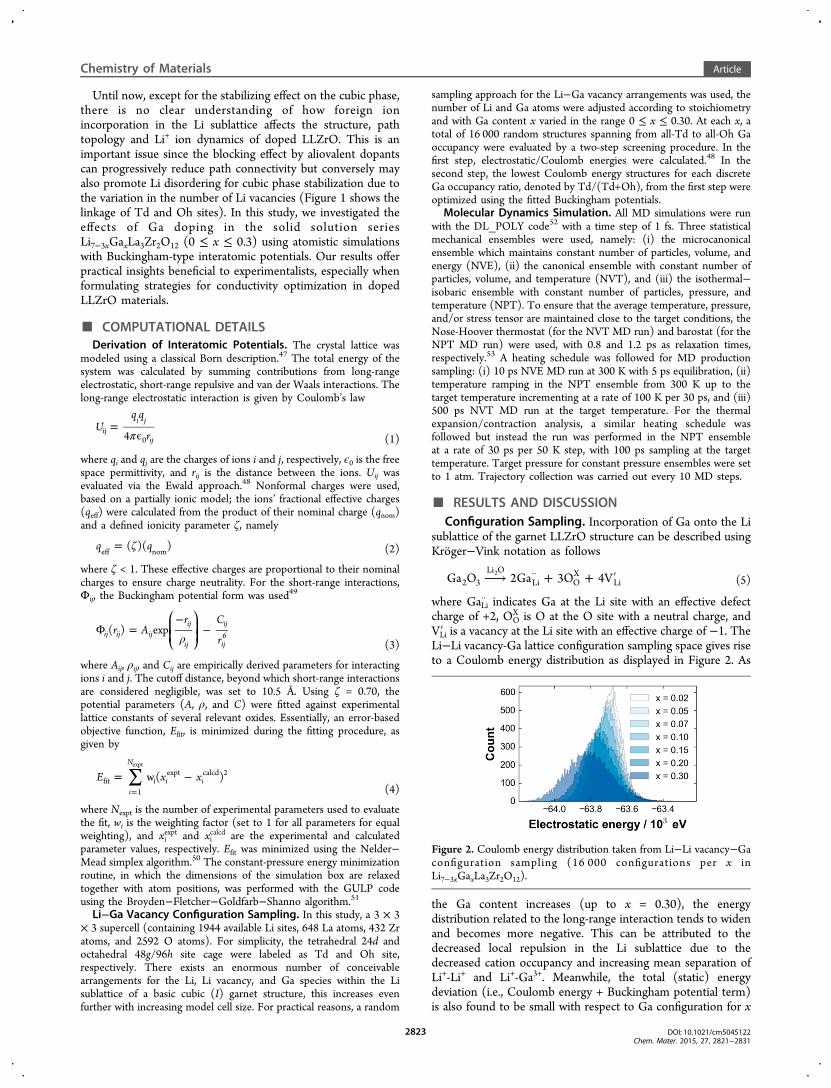
VLi′ is a vacancy at the Li site with an effective charge of −1. TheLi−Li vacancy-Ga lattice configuration sampling space gives riseto a Coulomb energy distribution as displayed in Figure 2. As
the Ga content increases (up to x = 0.30), the energydistribution related to the long-range interaction tends to widenand becomes more negative. This can be attributed to thedecreased local repulsion in the Li sublattice due to thedecreased cation occupancy and increasing mean separation ofLi+-Li+ and Li+-Ga3+. Meanwhile, the total (static) energydeviation (i.e., Coulomb energy + Buckingham potential term)is also found to be small with respect to Ga configuration for x
Figure 2. Coulomb energy distribution taken from Li−Li vacancy−Gaconfiguration sampling (16 000 configurations per x inLi7−3xGaxLa3Zr2O12).
Chemistry of Materials Article
DOI: 10.1021/cm5045122Chem. Mater. 2015, 27, 2821−2831
2823

≤ 0.3 (less than 10 meV/atom with a variation of less than 15meV/atom per x, see Figure S1 of the Electronic SupportingInformation). This implies that Ga3+ could sit in both Td andOh sites without significant energy penalty, partly explainingthe lack of consensus on the correct Ga3+ site preference in theliterature.18,42−44,46 Even with the inclusion of lattice vibrationeffects, this tendency is still preserved (see Figure S2 in theSupporting Information).Unless specified otherwise, the lowest total energy structures
at each value of x (Ga content) were used for the subsequentMD runs.Effect of Ga3+ toward Li Distribution, Structural
Distortion, and Topology. As previously mentioned, it wassuggested in experimental reports that Ga3+ leads to thestabilization of cubic phase for LLZrO. To confirm this, weanalyzed the Li distribution with respect to Ga3+ addition.Figure 3a shows the Li−Li radial distribution function g(r)profiles of undoped (x = 0) and Ga-doped (x = 0.30) 3 × 3 × 3supercell models for LLZrO (at 800 and 300 K). Vertical lines(dashed and solid) show the discrete peak locations for thetetragonal phase (note that due to cell edge mismatch, the firsttwo peak lines from the left are shifted to the right with respectto the cubic phase). It should also be mentioned at this pointthat owing to the scale of the phase space involved (1944 Lisites for a 3 × 3 × 3 supercell), standard MD sampling andannealing would require a prohibitively long computation timeto reach the exact Li ordering of the tetragonal phase (i.e., intothe 8a, 16f, and 32g sites25) when starting at the high-T Lidisordered cubic phase. In other words, in the presentcomputation, we would only observe the tendency for Liordering in the cooling direction, that is, tetragonal signaturesin the Li−Li g(r) profiles become more pronounced as we go
down to low temperature range (starting from a hightemperature phase) but the exact g(r) fingerprint of the fullyordered Li arrangement would not be reached. This isexplained as follows: if the tetragonal phase is formed, theoctahedral sites should be fully occupied and contributions for16f Li−32g Li pairs should become prominent within the range3.0 Å < r < 4.0 Å (first nearest neighbor, or first NN), 4.8 Å < r< 5.5 Å (2nd NN), and 6.3 Å < r < 7.0 Å (3rd NN); see thevertical solid lines in Figure 3a. Also, 1/3 of the Td sites shouldbe occupied in a regular arrangement such that Td Li+ do nothave a first nearest Td site neighbors, that is, 8a Li−16e Li paircontribution (for first NN Td site pairs) should become weakerat r ≈ 4 Å.25 In both models (x = 0 and x = 0.30), the first peakcan be readily assigned to the characteristic Td-Oh Li intersitecontribution. At 800 K, Li disordering is depicted in Figure 3aby the smoother peaks due to the ease of Li diffusivity (Figure3c, e). At 300 K, Li+ becomes localized at specific sites, shownas peak narrowing (Figure 3c) and peak splitting (Figure 3e)vis-a-vis the 800 K g(r) plots. Peaks for the 16f Li−32g Li paircontribution are slightly sharper (for first and second NN OhLi+) in the undoped model as compared to the doped case at300 K; this stems from the increased occupancy at octahedralLi sites for the former. In addition, a decrease in g(r) becomesevident at r ≈ 4 Å, this can be related to a weakening 8a Li−16eLi pair contribution. Collectively, these observations clearlypoint to a tendency for Li ordering in the undoped LLZrOmodel at 300 K for both heating and cooling directions.Meanwhile, the low g(r) at r ≈ 4 Å for the doped model cannotbe attributed to the Li ordering effect from the diminished firstNN Td site Li pair contribution, but instead due to Gaoccupancy in those sites (the selected lowest energy structure,such as for x = 0.30, mainly has Ga3+ at Td sites). Because of
Figure 3. (a) Calculated Li−Li radial distribution function g(r) profiles for undoped (x = 0; 300 and 800 K in the heating direction and 300 K in thecooling direction) and doped (x = 0.30; 800 K in the heating direction and 300 K in the cooling direction) 3 × 3 × 3 LLZrO cell models, (c)enlarged view of the g(r) plot in a highlighting the narrowing of the peak from 800 to 300 K in the range 1.5 Å ≤ r ≤ 3.0 Å (see arrows), and (e)enlarged view of the g(r) plot in a highlighting the peak splitting from 800 K (*) to 300 K (+) in the range 4.1 Å ≤ r ≤ 5.5 Å (see arrows). Verticallines (dashed and solid) indicate discrete peak locations for the tetragonal phase (8a-16f-32g). Thermal expansion plots with respect to themonitored reaction coordinates (lattice constants c and a) for: (b) undoped, (d) 1-Ga atom, and (f) 2-Ga atom 1 × 1 × 1 (I cell) models (Ga3+
added at the 24d site). Dashed lines show linear fitting for 600 K ≤ T ≤ 1000 K, in both heating (red) and cooling (blue) direction.
Chemistry of Materials Article
DOI: 10.1021/cm5045122Chem. Mater. 2015, 27, 2821−2831
2824

this, Li+ ions cannot assume the 8a-16f-32g arrangement fortetragonal phase formation in the Ga-doped model. Otherevidence for the lack of ordering tendency in the Ga-dopedmodel at 300 K are the broader peaks, the absence of a valleyregion at around r ≈ 3.0 Å, and shallower valleys at 4.5 Å < r <5.0 Å and r > 6.0 Å. Thus, we verify from the g(r) plots the lackof Li ordering tendency and consequently, the suppression ofthe tetragonal phase in the Ga-doped model.Another way of distinguishing the loss of tetragonal
character, on Ga addition, is by monitoring the thermalexpansion/contraction plots of undoped and doped LLZrOmodels. We started from a smaller 1 × 1 × 1 tetragonal (I41/acd) cell (72 Li sites) with no Ga, 1 Ga, and 2 Ga atom(s). Forthe 1-Ga cell, we replaced 1 Li atom at the 8a site and madesure the first NN sites (16f or 32g) are empty, to minimize localrepulsion (referred from the occupancy trend shown by lowesttotal energy structures). Similarly, for the 2-Ga cell, we replaced2 Li atoms at the 8a site. The number of Li atoms was thenadjusted accordingly for charge neutrality. We then monitoredthe cell edges, with the shortest one denoted as the latticeconstant c and the average of the remaining two as latticeconstant a, at every temperature step, and used them as keyreaction coordinates for detecting the phase transition. Weemployed this condition because c can switch between thethree cell edges because of the Li redistribution and cellsymmetry, especially below the transition temperature Tc. If thechosen coordinate only changes linearly with T, then only Lidisordering exists and there is no phase transition. If a bend inthe curve is observed, however, then it is identified as thetetragonal→ cubic topotactic structural transition. Figure 3b, d,and f shows the evolution of lattice constants c and a withrespect to temperature for an undoped cell, a cell with 1 Gaatom, and a cell with 2 Ga atoms, respectively. For the undopedcell, a bend in the thermal expansion plot is observed both inthe heating (red) and the cooling (blue) direction. The onset ofbending appears to start at ∼600 K; beyond this temperaturethe trend becomes linear. We assigned this bend as the phase
transition point. This value is in good agreement with someexperiments (>400 K)27,38 and with a recent classical MDsimulation (>450 K).27 On the other hand, the bend in thethermal data in Figure 3b has disappeared in both the heatingand cooling direction in Figure 3d, f (1 and 2 Ga atoms added,respectively), which signifies the suppression of the tetragonalphase. Thus, we again confirmed our prediction that the cubicphase can be effectively stabilized by Ga3+. The model cell weused with 2 Ga atoms (in an I cell) is equivalent to a dopinglevel of x = 0.25, but stabilization has also been achievedexperimentally at lower Ga-doping levels than this.44
To determine the extent of cell expansion/contraction withincreasing Ga3+, we plotted the average lattice constant withrespect to x in Figure 4a. The plot shows good agreementbetween calculated and XRD-derived lattice constants (<1%difference). Also, Ga3+ doping appears not to cause any severelattice constant change; several experimental studies related toLi pathway blocking dopants for LLZrO have arrived at thesame conclusion.13,38,42,44,54 We also checked whether Ga canpromote a more open local Li pathway by analyzing the voidspace when Li atoms are completely removed in the modelcells. The Zeo++ software was used to perform geometry-basedanalysis of structure and topology of the void space inside theLLZrO framework; it can determine the bottleneck size bycalculating the largest pore diameter along the Li pathway.55 Asa recap of the Li path topology, four Td faces related to the Tdsite (the pathway junction) form the path bottlenecks. Each ofthese faces are bounded by three O atoms as shown in Figure4b. Results for the pathway bottleneck size variation arecollected in Figure 4c. Clearly, no significant change is observedfor the bottleneck size, the same with cell edges (Figure 4a).Therefore, we conclude that Ga doping does not contribute toany appreciable structural distortion nor would it promote amore open pathway for Li diffusion. A similar observation wasmade in Rb-doped LLZrO, where even with the very large Rb+
(1.61 Å) chemically substituting for La3+ (1.16 Å), thebottleneck size does not readily expand nor contract.29
Figure 4. (a) Averaged lattice constant a from calculation and experiments, (b) illustration of the Li path bottleneck formed by the Td faces (redtriangular areas with O vertices), (c) Li path bottleneck size variation as a function of Ga content derived from 30 ps NPT MD sampling, and (d)percolation-based site connectivity fraction as a function of Ga content x (using a 10 × 10 × 10 supercell).
Chemistry of Materials Article
DOI: 10.1021/cm5045122Chem. Mater. 2015, 27, 2821−2831
2825

Another important factor to consider is the extent ofconnectivity disruption in the Li sublattice by progressiveblocking of Ga3+. For this analysis, we treated the system as athree-dimensional percolation problem.56 Two cases need to beevaluated in order to reveal the site connectivity relationship:exclusive Td-site blocking and a combination of Td- and Oh-site blocking. A sufficiently large supercell (10 × 10 × 10) wasused with 24 000 and 72 000 sites, respectively, in order tominimize periodic boundary condition effects. The results areplotted in Figure 4d. For the exclusive Td-site blocking case,the percolation threshold (pc) for Ga3+ is determined to beabout ∼2.34 mol p.f.u. which in terms of the stoichiometrywould lead to the full removal of Li+ (∼7.02 mol p.f.u.). Up to x= 0.30 however, site connectivity is still >90%. For thesimultaneous Td- and Oh-site blocking case, as expected, pcoccurs at a much higher Ga content (∼4.68 mol p.f.u.), which isalso way beyond the stoichiometric limit for Ga−Lisubstitution. On the basis of these results, we argue that site-blocking by Ga3+ does not severely deteriorate connectivity and
Li+ can still form a contiguous path extending from one side ofthe cell to the other.
Lithium Ion Dynamics and Diffusion Mechanism. Themotion of atoms were analyzed from their mean squaredisplacements (MSDs). Li MSD profiles for undoped (x = 0)and doped (x = 0.30) LLZrO in Figure 5a, b, respectively,display increasing linear trends vs MD sampling time anddiffusivity vs T. Framework atoms (La, Zr, and O) are noted toessentially just vibrate about their sites as confirmed by theirzero-slope MSD trends (see Figures S2 and S3 in theSupporting Information). These results are consistent withother simulation studies.25,26,29 In the case of Ga atoms (for x =0.30), their MSD starts to increase at 1200 K (Figure 5c). Thisonset temperature for Ga ion diffusion does not vary withrespect to Ga content (see Figure S4 in the SupportingInformation). In general, the integrity of the garnet structurehas been kept in all of the MD production runs for all dopinglevels considered, allowing us to reliably estimate the Li+ iondiffusion coefficient and activation energy values.
Figure 5. Mean square displacement (MSD) plots taken from 500 ps NVT MD simulations with respect to x in Li7−3xGaxLa3Zr2O12: (a, b) Li atoms(for x = 0 and x = 0.30, respectively; 600−1700 K), (c) Ga atoms (for x = 0.30; 600−1200 K), and (d) Li atoms occupying different Li sites (all-Tdand all-Oh Li sites, for x = 0.10 and x = 0.15, at 1000 K).
Figure 6. ⟨1 0 0⟩-view Ga trajectory density (4 × 10⁻⁵ Å−3 isosurface level, 25% max saturation) taken from 500 ps NVT MD simulations at (a)1000, (b) 1200, (c) 1400, and (d) 1700 K. The sampling interval for data collection is set to 100 fs.
Chemistry of Materials Article
DOI: 10.1021/cm5045122Chem. Mater. 2015, 27, 2821−2831
2826

To gain insights into the interplay between Li+ ion diffusivityand Ga distribution, we compared the MSD slopes betweenexclusive Td- and exclusive Oh-blocking model cells. Note thatthese two extremes are predicted to be energeticallycomparable (see Figure S1 in Supporting Information). Resultsare displayed in Figure 5d for compositions x = 0.10 and x =0.15 at 1000 K. Calculated diffusion coefficients are 2.53 × 10⁻⁵
cm2/s and 2.80 × 10⁻⁵ cm2/s for all-Td and all-Oh cases,respectively, for x = 0.10, and 2.33 × 10⁻⁵ cm2/s and 2.63 ×10⁻⁵ cm2/s for all-Td and all-Oh cases, respectively, for x =0.15. In these two doping levels, the all-Oh Ga cases aresystematically higher (by 11 and 13%, respectively) than the all-Td cases. This difference is consistent with (i) the spatialrelationship of Td and Oh sites, that is, the more critical Td siteforming a junction connecting four neighboring Oh sites andthe Oh site only oppositely face-sharing two Td sites, and (ii)the generally preserved site connectivity of the pathway(>90%), independent of Ga site preference (see Figure 4d).Consequently, for a mix of Td- and Oh-site Ga occupancy, theincrease in diffusivity relative to the all-Td Ga model isexpected to have an upper bound defined by the all-Oh case.The evolution of the Ga trajectory density for a Ga-doped
LLZrO model (x = 0.30, 500 ps NVT MD production run with1 fs step and 100 fs trajectory sampling) at increasingtemperature, is shown in Figure 6. Below the onset temperature(T = 1000 K in Figure 6a), Ga atoms are strongly localizedabout their sites. At T = 1200 K in Figure 6b, the vibrationsignature becomes bigger and some hints of next-nearest-neighbor-site hopping are becoming apparent, based on theincreased Ga density. As the temperature further increases(Figure 6c, d), more Ga3+ become delocalized from their initialsites, leading to limited Ga diffusion being possible withhopping up to third to fourth NN sites. This onset temperaturemay be exploited for conductivity optimization, either byinvestigating Ga redistribution in the bulk and/or Ga diffusionfrom surface to bulk at different heating rates and temperatures.Figure 7a displays the Arrhenius plots derived from MD
simulations; experimental data are also included for compar-ison. Following the Nernst−Einstein relationship, the bulk Li+
ion conductivity, σLi, can be calculated from57
σ = c (z F)DRTLi Li Li
2 Li(6)
where cLi is the carrier density for Li, zLi is Faraday’s constant, Ris gas constant, and T is temperature. The Li+ ion activationenergy (Ea) values are determined to be in the narrow range of0.24−0.30 eV, indicating that Ga3+ does not strongly affect theLi+ diffusion barrier height. Meanwhile, room temperature bulkconductivity, as indicated in Figure 7b, is calculated to be in therange 1.42−6.08 × 10⁻³ S/cm (the maximum at x = 0.02). Wewould like to emphasize here that the MD sampling procedureperformed for x = 0 is in the high temperature region (see circledata points in Figure 7a), so the simulation box already has acubic symmetry, and thus explaining the artificially highpredicted bulk conductivity. On the other hand, in the heatingdirection (at 300 K), the conductivity for x = 0 with thetetragonal phase is at least 2 orders of magnitude lower inconductivity than the Ga-doped cases. It is also visible from thetrend that a minimal Ga addition of x ≈ 0.05 is sufficient for thestabilization of the cubic phase.There appear to be two distinct regions in the high-T-derived
conductivity plot (vs x). For 0.00 ≤ x ≤ 0.10, the conductivitytends to decrease in a linear fashion, whereas for 0.10 ≤ x ≤
0.30, it tends to be flat. The existence of these two regions willbe clarified later. At present, Bernuy-Lopez et al. havesucceeded in achieving a conductivity of 1.3 × 10⁻³ S/cmwith their dense (94%) and air-/moisture-protectedLi6.55Ga0.15La3Zr2O12;
43 this value is very close to our prediction(1.6 × 10⁻³ S/cm at x = 0.15). The strong agreement couldmean two things: (i) that grain boundary resistance may besmall at this doping level, and (ii) that higher conductivityvalues could still be achieved experimentally by pushing towarda much lower Ga3+ doping concentration. However, con-ductivity in LLZrO-based solid electrolytes was shown to varygreatly in experiments due to differences in preparationconditions. Overall, important requirements were noted, suchas ensuring high density for the pellet samples and theprevention of H2O/CO2 uptake. A varying room temperatureconductivity was measured by Howard et al. with 0.50 molp.f.u. of Ga3+-doping and ∼80% dense samples (between 1 ×10⁻³ and 1 × 10⁻⁵ S/cm),42 possibly with a contribution as wellfrom H+/Li+ exchange.58 A further example of this variabilityare the results of Wolfenstine et al. in which they achieved∼91% dense samples with 0.25 mol p.f.u of Ga3+, resulting in atotal conductivity of 3.5 × 10⁻⁴ S/cm, much lower than the10−3 S/cm range.54 El Shinawi et al.45 substituted up to 1.0 molp.f.u. and achieved 92.5% density; they identified an increasingtrend in the measured conductivity to about 5.4 × 10⁻⁴ S/cm,although still <1 × 10⁻³ S/cm. They determined that not all theGa3+ ions were incorporated into the garnet structure, and that
Figure 7. (a) Comparison of Li+ ion conductivities for different Ga-doped LLZrO samples (calculated and experimental). Experimentaldata were taken from refs 42 (*), 43 (**), and 45 (***). Coloredcircle data points are MD simulation data above the predicted phasetransition temperature (Tc ≈ 600 K). (b) Predicted variation in bulkconductivity vs Ga content at room temperature as extrapolated fromthe high-temperature MD simulation data in a (colored circle datapoints) and as extracted from the 300 K MD run in the heatingdirection.
Chemistry of Materials Article
DOI: 10.1021/cm5045122Chem. Mater. 2015, 27, 2821−2831
2827
a portion ended up reacting with excess Li+ ions to formLiGaO2, which then resided at the grain boundaries; thissecondary phase was argued to have aided in pelletdensification. From these results, Ga3+ can also be consideredbeneficial as a sintering aid. It is important to note that in all theexperimental results quoted above, the total (bulk plus grainboundary) conductivity is reported, as it is difficult to resolvethe individual bulk and grain boundary components fromimpedance spectroscopy, and thus values are extremelysensitive to the microstructure of the measured samples.The two-region conductivity plot predicted in Figure 7b
suggests a shift in the nature of the Li+ ion diffusion within thegarnet framework. To elucidate this, we checked the variationin Li−Li space-time correlation and analyzed it with other datasuch as Li trajectory density, number of Li vacancies, Li siteblocking/connectivity/percolation and net mass transportchange. For the Li−Li space-time correlation, the distinctpart of the van Hove space-time correlation function wasanalyzed59
∑ ∑ δ= ⟨ − | − | ⟩≠
G r tN
r r t r( , )1
( ( ) (0) )i j
i jdi (7)
where N is the number of Li+ ions, δ(•) is the three-dimensional Dirac delta function, and rj and ri are displace-ments of particles j and i, respectively, at time t. Gd(r,t)accounts for probability of finding particle j at location r aftertime t, in relation to the position of another particle i at theinitial time t = 0. The main points relevant to the followingdiscussion can be enumerated as follows:
(i) when t = 0, Gd(r,t) collapses to the more commonlyknown static g(r) plot with the first peak characterized byTd-Oh intersite distance, in collaborative hopping, rj(t)− ri(t = 0) progressively approaches zero with time and
causes the Gd(r,t) contribution near r = 0 to increaserapidly
(ii) the local rearrangement of particles leads to a decreasingGd contribution over time.
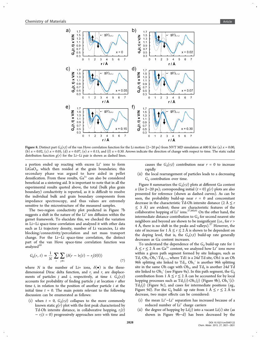
Figure 8 summarizes the Gd(r,t) plots at different Ga contentx (for 2−20 ps); corresponding initial (t = 0) g(r) plots are alsopresented for reference (shown as dashed curves). As can beseen, the probability build-up near r = 0 and concomitantdecrease in the characteristic Td-Oh intersite distance (2 Å ≤ r≤ 3 Å) are evident; these are characteristic features of thecollaborative hopping of Li+ ions.27,60,61 On the other hand, theintermediate distance contribution to Gd for second nearest siteneighbors and beyond are shown to be insignificant (i.e., for r >4 Å, there is no shift in the peaks and valleys).27 However, therate of increase for 1 Å ≤ r ≤ 2 Å is shown to be dependent onthe doping level, that is, the Gd(r,t) build-up rate generallydecreases as Ga content increases.To understand the dependence of the Gd build-up rate for 1
Å ≤ r ≤ 2 Å on Ga3+ content, we analyzed how Li+ ions movewithin a given path segment formed by site linkages, such asTd1-Oh1-Oh1’-Td2-..., where Td1 is a 24d Td site, Oh1 is an Oh96h splitting site linked to Td1, Oh1′ is another 96h splittingsite in the same Oh cage with Oh1, and Td2 is another 24d Tdsite linked to Oh1′ (see Figure 9a). In this path segment, the Gdcontribution from 1 Å ≤ r ≤ 2 Å can be accounted for by localhopping processes such as Td1(i)-Oh1(j) (Figure 9b), Oh1′(i)-Td2(j) (Figure 9c), and cases for intermediate positions (eg.,Figure 9d). For the Gd build- up rate from 1 Å ≤ r ≤ 2 Å todecrease, two major effects can be considered:
(i) the mean Li+−Li+ separation has increased because of areduced number of Li+ charge carriers
(ii) the degree of hopping by Li(j) into a vacant Li(i) site (asshown in Figure 9b−d) has been decreased by the
Figure 8. Distinct part Gd(r,t) of the van Hove correlation function for the Li motion (2−20 ps) from NVT MD simulation at 600 K for (a) x = 0.00,(b) x = 0.02, (c) x = 0.05, (d) x = 0.07, (e) x = 0.15, and (f) x = 0.30. Arrows indicate the direction of change with respect to time. The static radialdistribution function g(r) for the Li−Li pair is shown as dashed lines.
Chemistry of Materials Article
DOI: 10.1021/cm5045122Chem. Mater. 2015, 27, 2821−2831
2828

increasing number of guest Ga3+ cations, which trap theLi vacancies.
Because there is no appreciable change in the Li−Li g(r) plotvs x (see Figure S6 in Supporting Information), the first regionof the high-T-derived two-region conductivity plot in Figure 7b(0.00 ≤ x ≤ 0.10) may then be rationalized as being due to thesecond effect described above being imposed on the Li+-iondynamics. As Li vacancies are expected to be strongly coupledto the substitutional Ga3+, these vacancies become inaccessiblefor a migrating Li+ ion according to the following associationreactions
+ ′ → ′·· ·· ·Ga V {Ga V }Li Li Li Li (8)
′ + ′ → ′·· · ··{Ga V } V {Ga 2V }Li Li Li Li LiX
(9)
where {GaLi··VLi′ }· is a defect cluster formed by one Ga3+ and one
Li vacancy and {GaLi·· 2VLi′ }X is a neutral cluster formed by one
Ga3+ and two Li vacancies. The Ga−Li g(r) plots confirm thepresence of inaccessible Li sites around Ga3+ (see Figure S5a inthe Supporting Information); a radius enclosing up to thesecond NN sites tends to be occupied only with an average of∼1.20 Li+ ions at any time (cutoff radius: 4.4 Å). For a classicalionic conductor, a conductivity maximum is usually observed,based on eq 4, when vacancies are progressively added. Thepeak in the conductivity trend for 0.00 ≤ x ≤ 0.10 (see Figure7b) closely resembles this behavior. For the linear decrease inconductivity (for 0.05 ≤ x ≤ 0.10), higher order clusters may beinvolved as the Ga content is further increased, lowering thenumber of accessible vacancies
+ ′ → ′·· ··2Ga 4V {2Ga 4V }Li Li Li LiX
(10)
where {2GaLi·· 4VLi′ }X is a higher order neutral cluster formed by
2 Ga3+ and 4 Li vacancies. However, the flat trend for 0.10 < x≤ 0.30 cannot be explained in the same way, so other factorsmust act to prevent the conductivity decrease. A possibleresolution to this, is that the Li motion becomes more directedand coordinated within the retained percolated pathways. Notethat at higher x, the number of accessible or free Li vacancies
(i.e., not strongly coupled with Ga3+) and the average Ga3+-Li+
repulsion are expected to increase; these are made possible bythe fact that two new Li vacancies are created for every Ga3+ ionincorporated.The retention of percolated pathways with Ga3+ doping (as
confirmed in Figure 4d) is qualitatively shown in the Litrajectory comparison in Figure 10 between x = 0 and x = 0.30.
The 3D network pathway is clearly visible (Figure 10a, c) witha characteristic motif visible along the ⟨1 1 1⟩ direction. Thetrajectory of the x = 0 case is in strong agreement with a recentanalysis of neutron powder diffraction data62 as well as severalsimulation studies.25−27,29 To make a clear comparison with thex = 0.30 case, we chose an appropriate slab section to exposethe full 2D plane view of Li pathway connectivity, such as plane(3 6 4), which is shown in blue in Figure 10a and 10c. As canbe seen, pathway features such as junctions formed by Td sites(LiO4) and density lobes formed by Oh sites (LiO6) can beobserved in detail (Figure 10b, d). For the doped case (x =0.30, Figure 10d), Li+ ion transport pathways are evidentlyinterrupted by Ga3+, as shown by some segments of thenetwork illustrated by the trajectory densities being absent (forx = 0.30). However, there are still percolated pathways thatremain, making long-range Li+-ion transport possible. Integra-tion of results from the first peak of the Li−Li radialdistribution function (RDF) plots g(r) have revealed no dropon the Li neighbor atom count with x (cutoff radius: 3.85 Å);∼2.18 to ∼2.25 Li atoms for x = 0 to x = 0.30 (see Figure S5bin the Supporting Information). This is consistent with havingsustained or directed concerted Li+ motion in the retainedpercolated pathways at higher x, as discussed in the previousparagraph.
Figure 9. (a) Illustration of the Li site linkage within the garnetLLZrO framework. Td1, Td2, Td3, and Td4 are 24d sites inside distinctTd cages (black), whereas Oh1-Oh1′, Oh2-Oh2′, and Oh3-Oh3′ are 96hsite pairs inside distinct Oh cages (white). A typical site-to-siteconnection can be described as Td1-Oh1-Oh1’-Td2-Oh2-Oh2’-Td3-Oh3-Oh3’-Td4. (b−d) Idealized representations of site separations for Li(i)-Li(j) within 1 Å ≤ r ≤ 2 Å of the distinct part of the van Hove Gd(r,t)plot: Td1(i)-Oh1(j), Oh1′(i)-Td2(j), and a case with an intermediateposition for Li(j), respectively.
Figure 10. ⟨1 1 1⟩-view of Li trajectory density (4 × 10⁻⁵ Å−3
isosurface level, 25% max saturation) for (a) x = 0 (cubic phase) and(c) x = 0.30 and their corresponding (b, d) selected two-dimensionalslab section views, respectively, projected on the [3 6 4] direction andhighlighting the path connectivity formed by Td and Oh sites. {3 6 4}Cutting planes are shown in blue. Red arrows and the dashed lineindicate lost Li paths and percolated Li pathway (retained),respectively, after Ga3+ doping. The sampling interval for datacollection is set to 100 fs.
Chemistry of Materials Article
DOI: 10.1021/cm5045122Chem. Mater. 2015, 27, 2821−2831
2829

■ CONCLUSIONThe effects of Ga-doping on garnet-type LLZrO wassuccessfully investigated through force-field-based simulationsusing Buckingham short-range potentials. We found that Ga3+
can effectively stabilize the cubic phase. Ga3+ incorporationdoes not change the lattice constant nor contribute to anysignificant structural distortion. The onset temperature for Gadiffusion is predicted to be about 1200 K. For the cubic lattice,two distinct regions in the conductivity behavior were observedfor 0 ≤ x ≤ 0.30. For 0 ≤ x ≤ 0.10, a decreasing trend is noted,whereas for 0.10 ≤ x ≤ 0.30, a flat trend is observed. Theformer can be explained primarily by the increasing number ofinaccessible Li vacancies (due to Ga3+−Li vacancy clusterformation) for use in initiating Li+ ion migration and concertedLi+ motion. The latter is likely governed by the subsequentincrease in the number of accessible Li vacancies (at higher x)and the more directed motion of Li+ ions in retained percolatedpathways due to the increasing average Ga3+−Li+ repulsion.
■ ASSOCIATED CONTENT*S Supporting InformationEvaluation of fitted potential parameters, Tables S1−S3,Figures S1−S6. This material is available free of charge viathe Internet at http://pubs.acs.org.
■ AUTHOR INFORMATIONCorresponding Author*E-mail: [email protected].
NotesThe authors declare no competing financial interest.
■ ACKNOWLEDGMENTSR.J. is grateful for financial support from Nagoya KogyokaiScholarship, Nagoya Institute of Technology. The present workwas partially supported by JST, PRESTO-program, and MEXTprogram “Elements Strategy Initiative to Form Core ResearchCenter” (Since 2012), MEXT, Ministry of Education Culture,Sports, Science and Technology, Japan. Crystal structures andisosurfaces were created using the VESTA software.63
■ REFERENCES(1) Thangadurai, V.; Kaack, H.; Weppner, W. J. Am. Ceram. Soc.2003, 86, 437−440.(2) Murugan, R.; Thangadurai, V.; Weppner, W. Angew. Chem., Int.Ed. 2007, 46, 7778−7781.(3) Liu, Z.; Huang, F.; Yang, J.; Wang, Y.; Sun, J. Solid State Sci. 2008,10, 1429−1433.(4) Kumar, B.; Kumar, J.; Leese, R.; Fellner, J. P.; Rodrigues, S. J.;Abraham, K. M. J. Electrochem. Soc. 2010, 157, A50−A54.(5) Kotokubi, M.; Munakata, H.; Kanamura, K.; Sato, Y.; Yoshida, T.J. Electrochem. Soc. 2010, 157, A1076−A1079.(6) Ramzy, A.; Thangadurai, V. ACS Appl. Mater. Interfaces 2010, 2,385−390.(7) Etacheri, V.; Marom, R.; Elazari, R.; Salitra, G.; Aurbach, D.Energy Environ. Sci. 2011, 4, 3243−3262.(8) Awaka, J.; Kijima, N.; Hayakawa, H.; Akimoto, J. J. Solid StateChem. 2009, 182, 2046−2052.(9) Wolfenstine, J.; Rangasamay, E.; Allen, J. L.; Sakamoto, J. J. PowerSources 2012, 208, 193−196.(10) Kokal, I.; Somer, M.; Notten, P. H. L.; Hintzen, H. T. Solid StateIonics 2011, 185, 42−46.(11) Janani, N.; Ramakumar, S.; Dhivya, L.; Deviannapoorani, C.;Saranya, K.; Murugan, R. Ionics 2011, 17, 575−580.
(12) Xie, H.; Alonso, J. A.; Li, Y.; Fernandez-Díaz, M. T.;Goodenough, J. B. Chem. Mater. 2011, 23, 3587−3589.(13) Shimonishi, Y.; Toda, A.; Zhang, T.; Hirano, A.; Imanishi, N.;Yamamoto, O.; Takeda, Y. Solid State Ionics 2011, 183, 48−53.(14) Xie, H.; Li, Y.; Goodenough, J. B. Mater. Res. Bull. 2012, 47,1229−1232.(15) Deviannapoorani, C.; Dhivya, L.; Ramakumar, S.; Murugan, R. J.Power Sources 2013, 240, 18−25.(16) Li, Y.; Han, J.- T.; Wang, C.- A.; Xie, H.; Goodenough, J. B. J.Mater. Chem. 2012, 22, 15357−15361.(17) Thompson, T.; Wolfenstine, J.; Allen, J. L.; Johannes, M.; Huq,A.; David, I. N.; Sakamoto, J. J. Mater. Chem. A 2014, 2, 13431−13436.(18) Allen, J. L.; Wolfenstine, J.; Rangasamy, E.; Sakamoto, J. J. PowerSources 2012, 206, 315−319.(19) Ishiguro, K.; Nemori, H.; Sunahiro, S.; Nakata, Y.; Sudo, R.;Matsui, M.; Takeda, Y.; Yamamoto, O.; Imanishi, N. J. Electrochem. Soc.2014, 161, A668−A674.(20) Ohta, S.; Kobayashi, T.; Asaoka, T. J. Power Sources 2011, 196,3342.(21) Ramakumar, S.; Satyanarayana, L.; Manorama, S. V.; Murugan,R. Phys. Chem. Chem. Phys. 2013, 15, 11327−11338.(22) Dumon, A.; Huang, M.; Shen, Y.; Nan, C.-W. Solid State Ionics2013, 243, 36−41.(23) Kihira, Y.; Ohta, S.; Imagawa, H.; Asaoka, T. ECS Electrochem.Lett. 2013, 2, A56−A59.(24) Hanc, E.; Zając, W.; Molenda, J. Solid State Ionics 2014, 262,617−621.(25) Jalem, R.; Yamamoto, Y.; Shiiba, H.; Nakayama, M.; Munakata,H.; Kasuga, T.; Kanamura, K. Chem. Mater. 2013, 25, 425−430.(26) Meier, K.; Laino, T.; Curioni, A. J. Phys. Chem. C 2014, 118,6668−6679.(27) Adams, S.; Rao, R. P. J. Mater. Chem. 2012, 22, 1426−1434.(28) Wang, Y.; Huq, A.; Lai, W. Solid State Ionics 2014, 255, 39−49.(29) Miara, L. J.; Ong, S. P.; Mo, Y.; Richards, W. D.; Park, Y.; Lee,J.-M.; Lee, H. S.; Ceder, G. Chem. Mater. 2013, 25, 3048−3055.(30) Bernstein, N.; Johannes, M. D. Phys. Rev. Lett. 2012, 109,205702.(31) Nakayama, M.; Kotobuki, M.; Munakata, H.; Nogami, M.;Kanamura, K. Phys. Chem. Chem. Phys. 2012, 14, 10008−10014.(32) KC, S.; Longo, R. C.; Xiong, K.; Cho, K. Solid State Ionics 2014,261, 100−105.(33) Kumazaki, S.; Iriyama, Y.; Kim, K.-H.; Murugan, R.; Tanabe, K.;Yamamoto, K.; Hirayama, T.; Ogumi, Z. Electrochem. Commun. 2011,13, 509−512.(34) Jin, Y.; McGinn, P. J. J. Power Sources 2011, 196, 8683−8687.(35) Li, Y.; Han, J.-T.; Wang, C.-A.; Vogel, S. C.; Xie, H.; Xu, M.;Goodenough, J. B. J. Power Sources 2012, 209, 278−281.(36) Wang, D.; Zhong, G.; Dolotko, O.; Li, Y.; McDonald, M. J.; Mi,J.; Fu, R.; Yang, Y. J. Mater. Chem. A 2014, 2, 20271−20279.(37) Buschmann, H.; Dolle, J.; Berendts, S.; Kuhn, A.; Bottke, P.;Wilkening, M.; Heitjans, P.; Senyshyn, A.; Ehrenberg, H.; Lotnyk, A.;Duppel, V.; Kienle, L.; Janek, J. Phys. Chem. Chem. Phys. 2011, 13,19378−19392.(38) Geiger, G. A.; Alekseev, E.; Lazic, B.; Fisch, M.; Armbruster, T.;Langner, R.; Fechtelkord, M.; Kim, N.; Pettke, T.; Weppner, W. Inorg.Chem. 2011, 50, 1089−1097.(39) Rettenwander, D.; Blaha, P.; Laskowski, R.; Schwarz, K.; Bottke,P.; Wilkening, M.; Geiger, C. A.; Amthauer, G. Chem. Mater. 2014, 26,2617−2623.(40) Duvel, A.; Kuhn, A.; Robben, L.; Wilkening, M.; Heitjans, P. J.Phys. Chem. C 2012, 116, 15192−15202.(41) Huang, M.; Shen, W. X. Y.; Lin, Y.-H.; Nan, C.-W. Electrochim.Acta 2014, 115, 581−586.(42) Howard, M. A.; Clemens, O.; Kendrick, E.; Knight, K. S.;Apperly, D. C.; Anderson, P. A.; Slater, P. R. Dalton Trans. 2012, 41,12048−12053.(43) Bernuy-Lopez, C.; Manalastas, W., Jr.; Del Amo, J. M. L.;Aguadero, A.; Aguesse, F.; Kilner, J. A. Chem. Mater. 2014, 26, 3610−3617.
Chemistry of Materials Article
DOI: 10.1021/cm5045122Chem. Mater. 2015, 27, 2821−2831
2830

(44) Rettenwander, D.; Geiger, C. A.; Tribus, M.; Tropper, P.;Amthauer, G. Inorg. Chem. 2014, 53, 6264−6269.(45) El Shinawi, H.; Janek, J. J. Power Sources 2013, 225, 13−19.(46) Geller, S. Z. Kristallogr. 1967, 125, 1−47.(47) Mayer, J.; Born, M. J. Chem. Phys. 1933, 270−279.(48) Ewald, P. Ann. Phys. 1921, 369, 253−287.(49) Buckingham, R. A. Proc. R. Soc. London, Ser. A 1938, 168, 264−283.(50) Nelder, J. A.; Mead, R. Comput. J. 1965, 7, 308−313.(51) Gale, J. D. J. Chem. Soc. Faraday Trans. 1997, 93, 629−637.(52) Smith, W.; Forester, T. R. J. Mol. Graphics 1996, 14, 136−141.(53) Hoover, W. G. Phys. Rev. A 1985, 31, 1695−1697.(54) Wolfenstine, J.; Ratchford, J.; Rangasamy, E.; Sakamoto, J.;Allen, J. L. Mater. Chem. Phys. 2012, 134, 571−575.(55) Willems, T. F.; Rycroft, C. H.; Kazi, M.; Meza, J. C.; Haranczyk,M. Microporous Mesoporous Mater. 2012, 149, 134−141.(56) Stauffer, D. Phys. Rep. Phys. Lett. 1979, 54, 1−74.(57) Zahn, D. J. Mol. Model. 2011, 17, 1531−1535.(58) Ma, C.; Rangasamy, E.; Liang, C.; Sakamoto, J.; More, K. L.;Chi, M. Angew. Chem. 2014, 126, 1−6.(59) van Hove, L. Phys. Rev. 1954, 95, 249−262.(60) Xu, M.; Ding, J.; Ma, E. Appl. Phys. Lett. 2012, 101, 031901.(61) Wang, Y.; Klenk, M.; Page, K.; Lai, W. Chem. Mater. 2014, 26,5613−5624.(62) Han, J.; Zhu, J.; Li, Y.; Yu, X.; Wang, S.; Wu, G.; Xie, H.; Vogel,S. C.; Izumi, F.; Momma, K.; Kawamura, Y.; Huang, Y.; Goodenough,J. B.; Zhao, Y. Chem. Commun. 2012, 48, 9840−9842.(63) Momma, K. J. Appl. Crystallogr. 2008, 41, 653−658.
Chemistry of Materials Article
DOI: 10.1021/cm5045122Chem. Mater. 2015, 27, 2821−2831
2831