Embed Size (px)
Citation preview
1
EE750Advanced Engineering Electromagnetics
Lecture 3
2EE750,2003, Dr. Mohamed Bakr
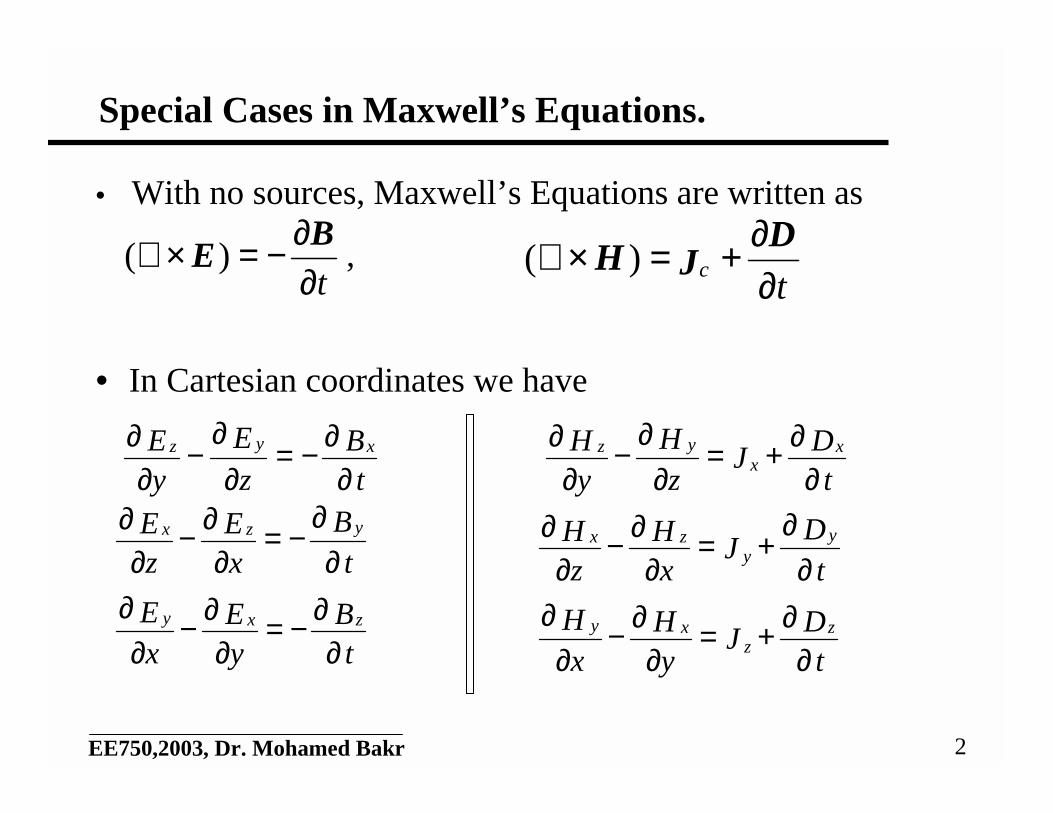
Special Cases in Maxwell’s Equations.
• With no sources, Maxwell’s Equations are written as
,
• In Cartesian coordinates we have
t∂∂−=×∇ B
E)(t
c ∂∂+=×∇ D
JH )(
tB
zE
yE xyz
∂∂−=
∂∂
−∂
∂
tB
xE
zE yzx
∂∂
−=∂
∂−∂
∂
tB
yE
xE zxy
∂∂−=
∂∂−
∂∂
tD
Jz
HyH x
xyz
∂∂+=
∂∂
−∂
∂
tD
JxH
zH y
yzx
∂∂
+=∂
∂−∂
∂
tD
JyH
xH z
zxy
∂∂+=
∂∂−
∂∂
3EE750,2003, Dr. Mohamed Bakr
Special Cases (Cont’d)
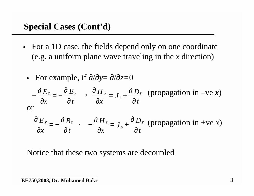
• For a 1D case, the fields depend only on one coordinate(e.g. a uniform plane wave traveling in the x direction)
• For example, if ∂/∂y= ∂/∂z=0
, (propagation in –ve x)
or
, (propagation in +ve x)
Notice that these two systems are decoupled
tB
xE yz
∂∂
−=∂
∂−t
DJ
xH z
zy
∂∂+=
∂∂
tB
xE zy
∂∂−=
∂∂
tD
JxH y
yz
∂∂
+=∂
∂−
4EE750,2003, Dr. Mohamed Bakr
Special Cases (Cont’d)
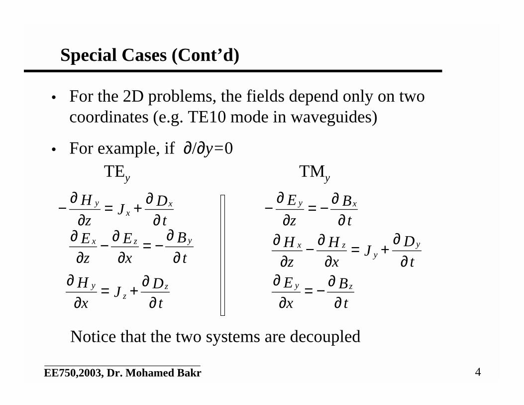
• For the 2D problems, the fields depend only on twocoordinates (e.g. TE10 mode in waveguides)
• For example, if ∂/∂y=0
tB
zE xy
∂∂−=
∂∂
−
tB
xE
zE yzx
∂∂
−=∂
∂−∂
∂
tB
xE zy
∂∂−=
∂∂
tD
Jz
H xx
y
∂∂+=
∂∂
−
tD
JxH
zH y
yzx
∂∂
+=∂
∂−∂
∂
tD
Jx
H zz
y
∂∂+=
∂∂
TEy TMy
Notice that the two systems are decoupled
5EE750,2003, Dr. Mohamed Bakr
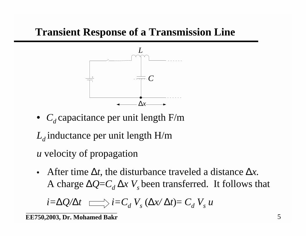
Transient Response of a Transmission Line
• Cd capacitance per unit length F/m
Ld inductance per unit length H/m
u velocity of propagation
• After time ∆t, the disturbance traveled a distance ∆x.A charge ∆Q=Cd ∆x Vs been transferred. It follows that
i=∆Q/∆t i=Cd Vs (∆x/ ∆t)= Cd Vs u
x∆
C
L
6EE750,2003, Dr. Mohamed Bakr
Transient Response of a TL (Cont’d)
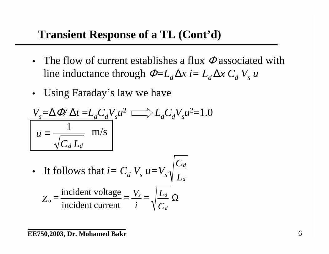
• The flow of current establishes a flux Φ associated withline inductance through Φ=Ld ∆x i= Ld ∆x Cd Vs u
• Using Faraday’s law we have
Vs=∆Φ/ ∆t =LdCdVsu2 LdCdVsu
2=1.0
m/s
• It follows that i= Cd Vs u=Vs
LCu
dd
1=
L
C
d
d
Ω===C
LiV
Zd
ds
currentincident
voltageincidento
7EE750,2003, Dr. Mohamed Bakr
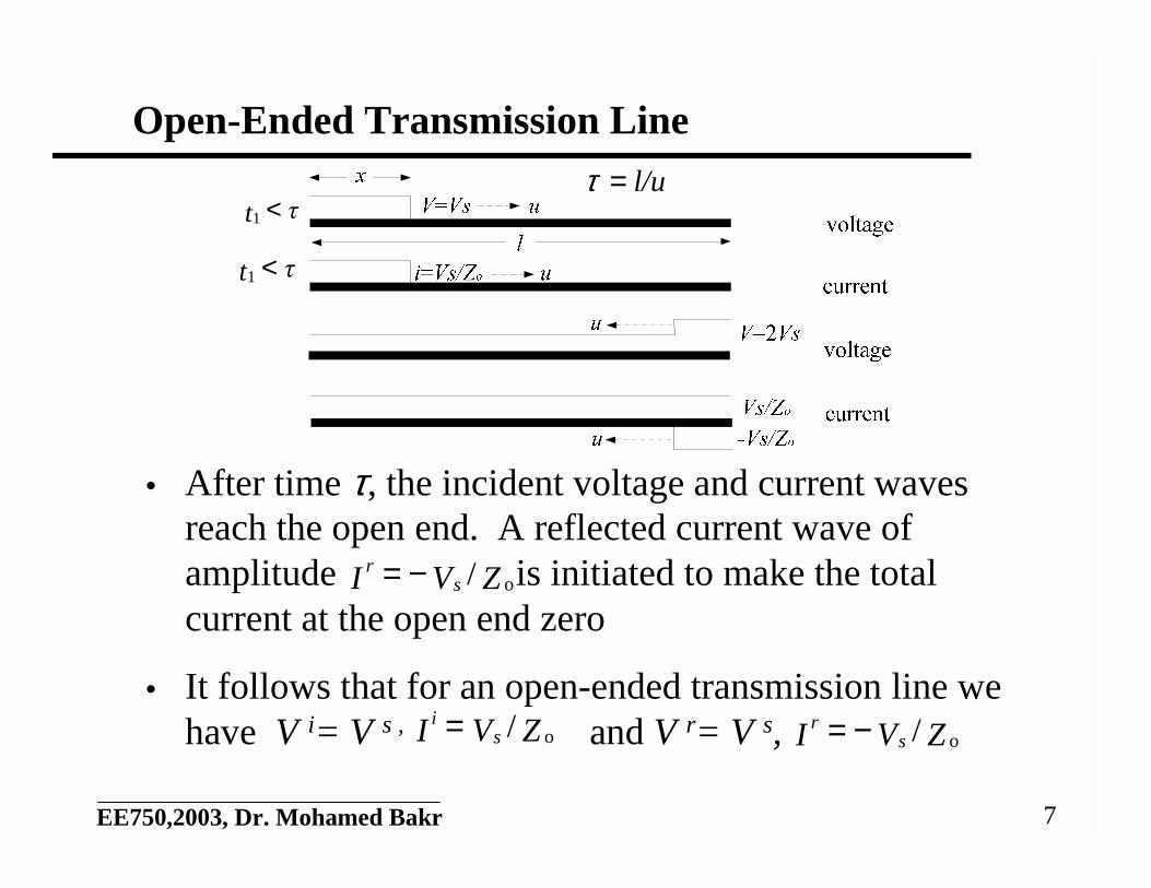
Open-Ended Transmission Line
• After time τ, the incident voltage and current wavesreach the open end. A reflected current wave ofamplitude is initiated to make the totalcurrent at the open end zero
• It follows that for an open-ended transmission line wehave V i= V s , and V r= V s,
ZVI sr
o/−=
ZVI si
o/= ZVI sr
o/−=
τt <1
τt <1
l/u=τ
8EE750,2003, Dr. Mohamed Bakr
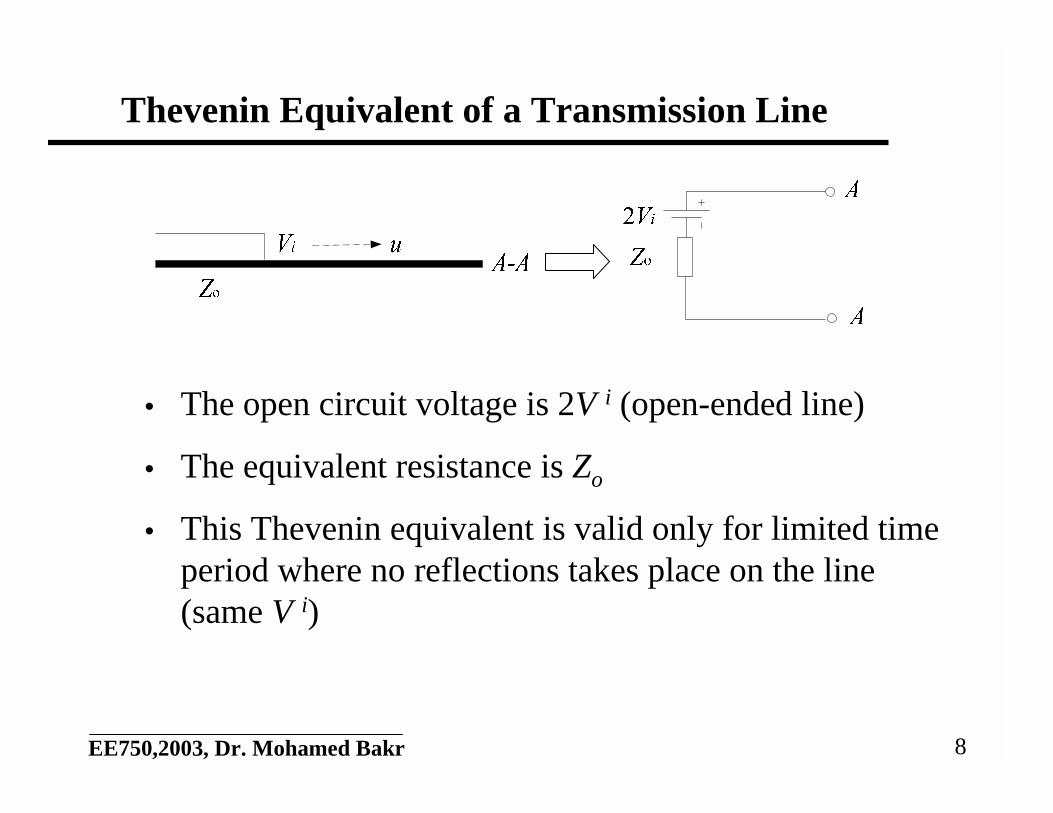
Thevenin Equivalent of a Transmission Line
• The open circuit voltage is 2V i (open-ended line)
• The equivalent resistance is Zo
• This Thevenin equivalent is valid only for limited timeperiod where no reflections takes place on the line(same V i)
9EE750,2003, Dr. Mohamed Bakr
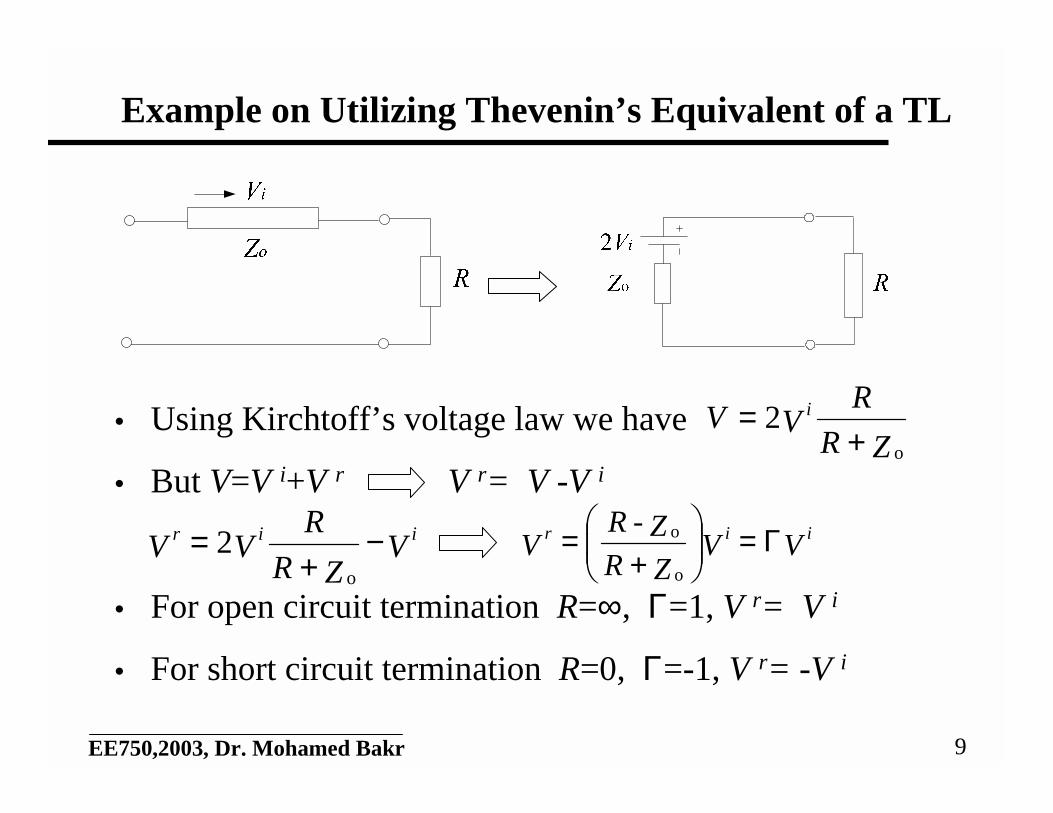
Example on Utilizing Thevenin’s Equivalent of a TL
• Using Kirchtoff’s voltage law we have
• But V=V i+V r V r= V -V i
• For open circuit termination R=∞, Γ=1, V r= V i
• For short circuit termination R=0, Γ=-1, V r= -V i
ZR
RVV i
o
2+
=
VZR
RVV iir −
+=
o
2 VVZRZ-R
V iir Γ=
+
=o
o
10EE750,2003, Dr. Mohamed Bakr
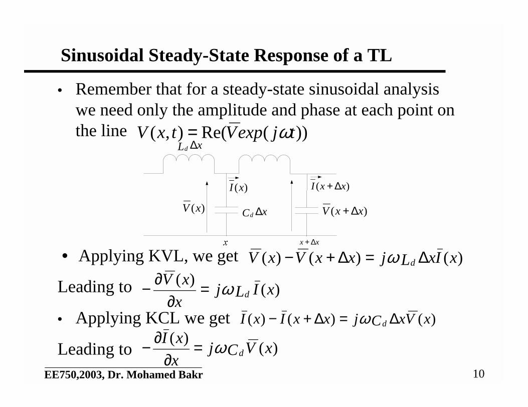
• Remember that for a steady-state sinusoidal analysiswe need only the amplitude and phase at each point onthe line
• Applying KVL, we get
Leading to
• Applying KCL we get
Leading to
Sinusoidal Steady-State Response of a TL
))(Re(),( tjexpVtxV ω=
)()()( xIxLjxxVxV d ∆=∆+− ω
)()(
xILjx
xVdω=
∂∂−
)()()( xVxCjxxIxI d ∆=∆+− ω
)()(
xVCjx
xIdω=
∂∂−
xx ∆+
xLd ∆
xCd ∆)(xV )( xxV ∆+
)(xI )( xxI ∆+
11EE750,2003, Dr. Mohamed Bakr
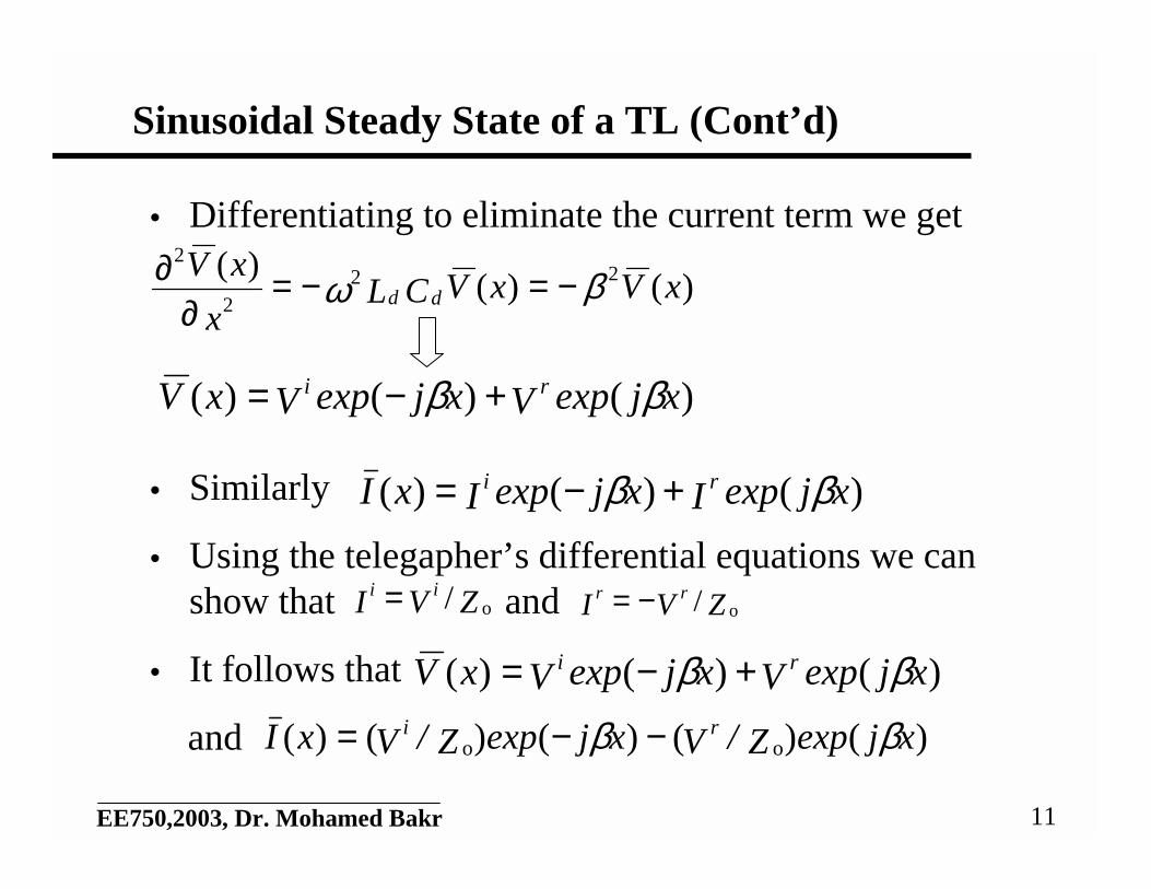
Sinusoidal Steady State of a TL (Cont’d)
• Differentiating to eliminate the current term we get
• Similarly
• Using the telegapher’s differential equations we canshow that and
• It follows that
and
)()()( 22
2
2
xVxVCLx
xVdd βω −=−=
∂∂
)()()( xjexpVxjexpVxV ri ββ +−=
)()()( xjexpIxjexpIxI ri ββ +−=
ZVI iio/= ZVI rr
o/−=
)()()( xjexpVxjexpVxV ri ββ +−=
)()()()()( oo xjexpZ/VxjexpZ/VxI ri ββ −−=
12EE750,2003, Dr. Mohamed Bakr
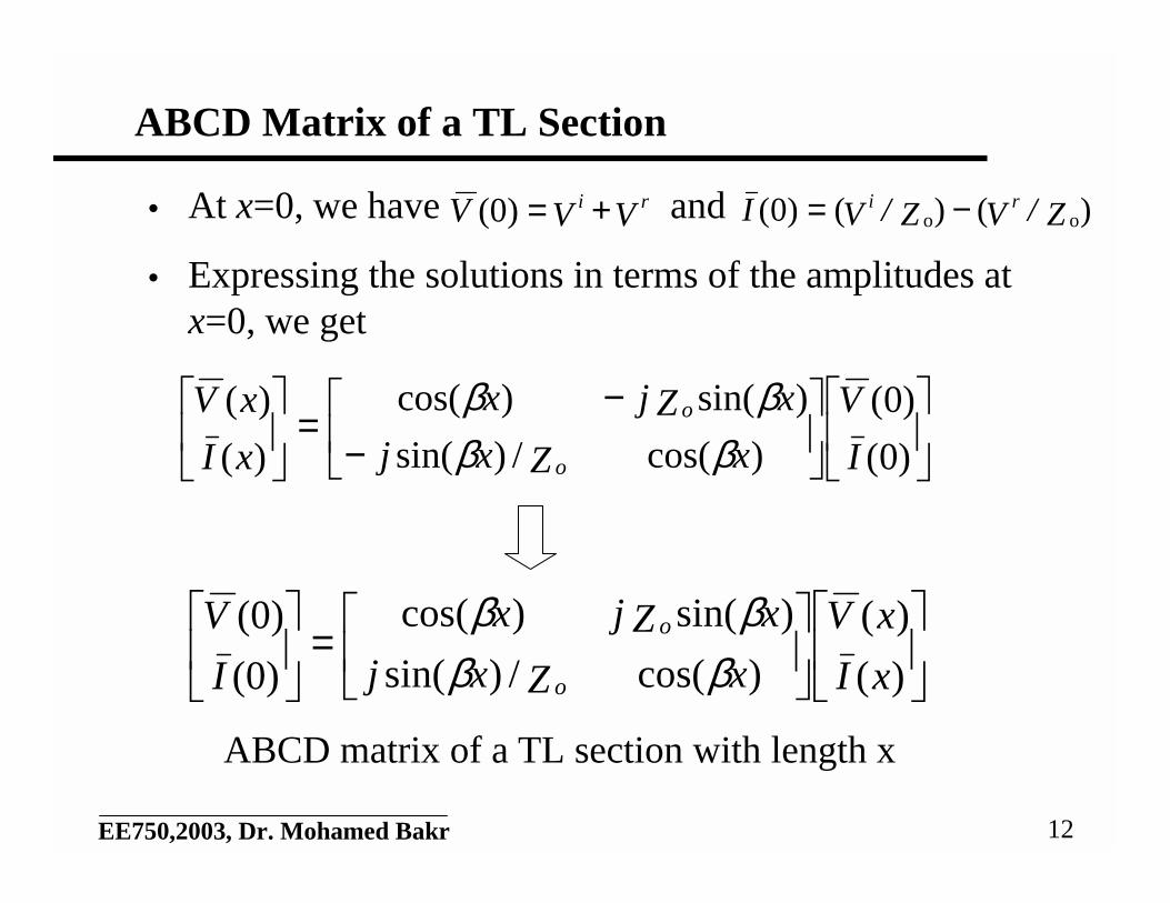
ABCD Matrix of a TL Section
• At x=0, we have and
• Expressing the solutions in terms of the amplitudes atx=0, we get
VVV ri +=(0) )()()0( oo Z/VZ/VI ri −=
−
−=
)0(
)0(
)cos(/)sin(
)sin()cos(
)(
)(
I
V
xZxj
xZjx
xI
xV
o
o
ββββ
=
)(
)(
)cos(/)sin(
)sin()cos(
(0)
(0)
xI
xV
xZxj
xZjx
I
V
o
o
ββββ
ABCD matrix of a TL section with length x
13EE750,2003, Dr. Mohamed Bakr
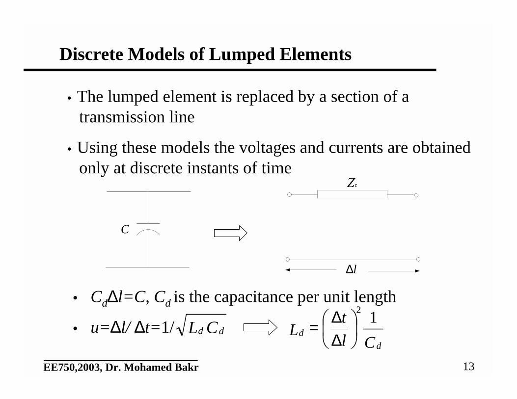
Discrete Models of Lumped Elements
• The lumped element is replaced by a section of atransmission line
• Using these models the voltages and currents are obtainedonly at discrete instants of time
• Cd∆l=C, Cd is the capacitance per unit length
• u=∆l/ ∆t=1/ CL ddCl
tL
dd
12
∆∆=
l∆
C
14EE750,2003, Dr. Mohamed Bakr
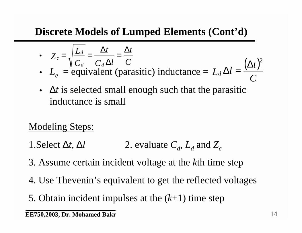
Discrete Models of Lumped Elements (Cont’d)
•
• Le = equivalent (parasitic) inductance =
• ∆t is selected small enough such that the parasiticinductance is small
C
t
lC
t
C
LZ
dd
dc
∆=∆
∆==( )
C
tlLd
∆=∆2
Modeling Steps:
1.Select ∆t, ∆l 2. evaluate Cd, Ld and Zc
3. Assume certain incident voltage at the kth time step
4. Use Thevenin’s equivalent to get the reflected voltages
5. Obtain incident impulses at the (k+1) time step
15EE750,2003, Dr. Mohamed Bakr
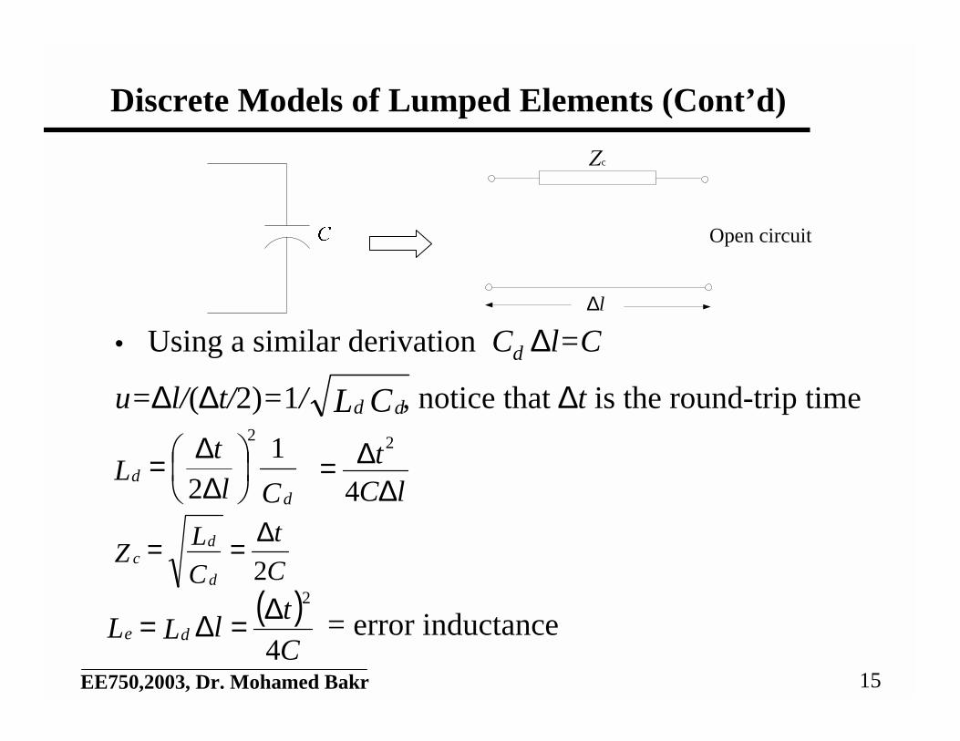
Discrete Models of Lumped Elements (Cont’d)
• Using a similar derivation Cd ∆l=C
u=∆l/(∆t/2)=1/ , notice that ∆t is the round-trip time
= error inductance
CL dd
Cl
tL
dd
12
2
∆∆=
lCt∆
∆=4
2
C
t
C
LZ
d
dc
2
∆==
( )C
tlLL de
4
2∆=∆=
Zc
l∆
Open circuit
16EE750,2003, Dr. Mohamed Bakr
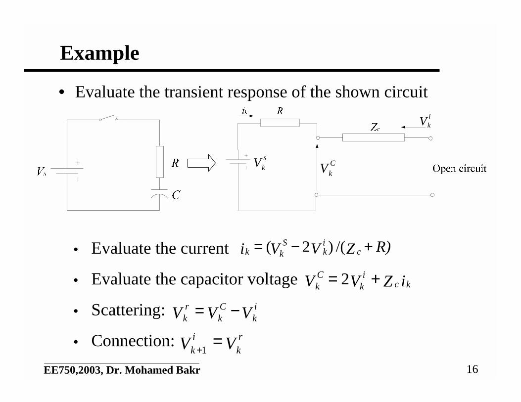
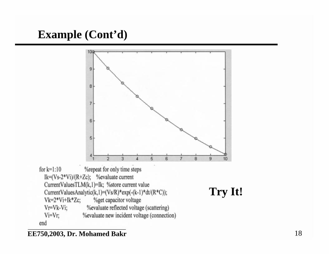
Example
• Evaluate the transient response of the shown circuit
• Evaluate the current
• Evaluate the capacitor voltage
• Scattering:
• Connection:
R)ZVVi cik
Skk +−= /()2(
iZVV kci
kCk += 2
VVV ik
Ck
rk −=
VV rk
ik
=+1
V ik
V sk V C
k
17EE750,2003, Dr. Mohamed Bakr
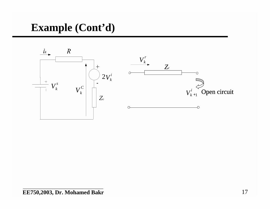
Example (Cont’d)
V sk V C
k
V ik2
Open circuitOpen circuit
Zc
V rk
V ik 1+
18EE750,2003, Dr. Mohamed Bakr
Example (Cont’d)
Try It!
19EE750,2003, Dr. Mohamed Bakr
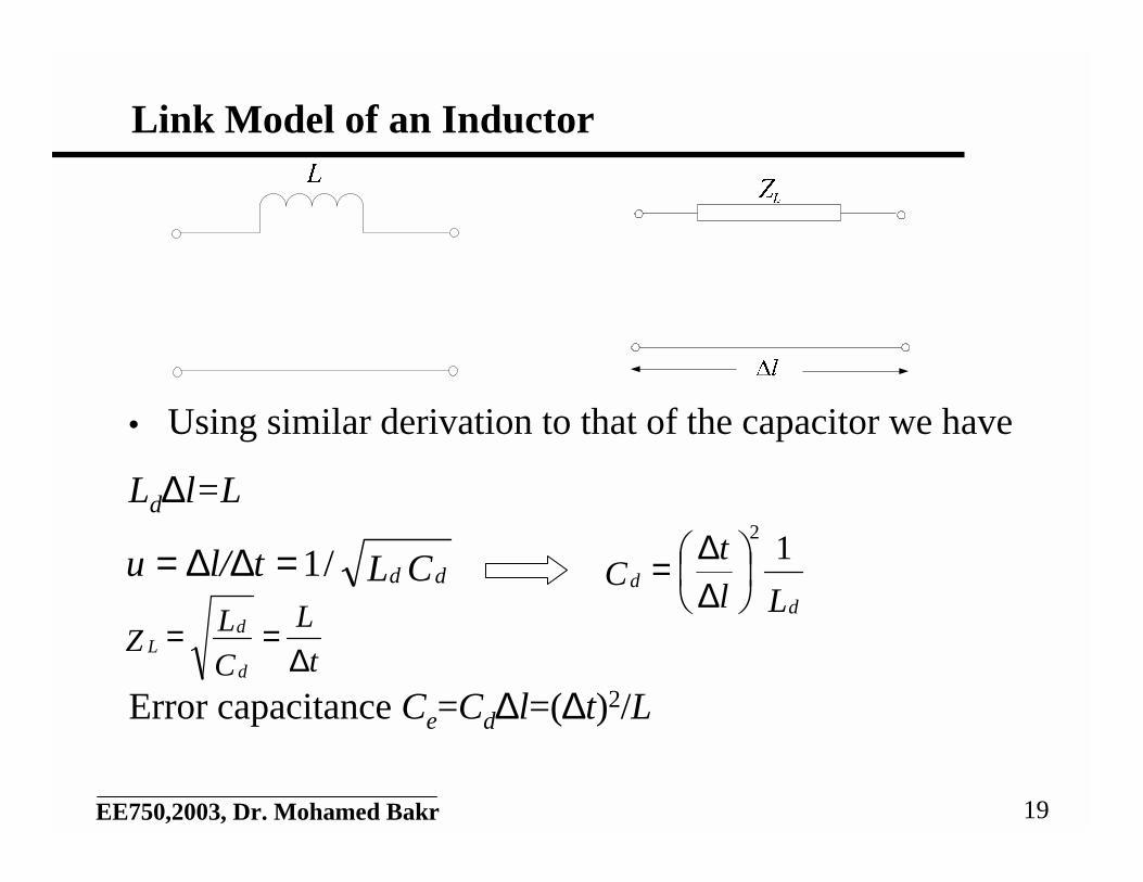
Link Model of an Inductor
• Using similar derivation to that of the capacitor we have
Ld∆l=L
Error capacitance Ce=Cd∆l=(∆t)2/L
CLtl/u dd/1=∆∆=Ll
tC
dd
12
∆∆=
t
L
C
LZ
d
dL ∆
==
20EE750,2003, Dr. Mohamed Bakr
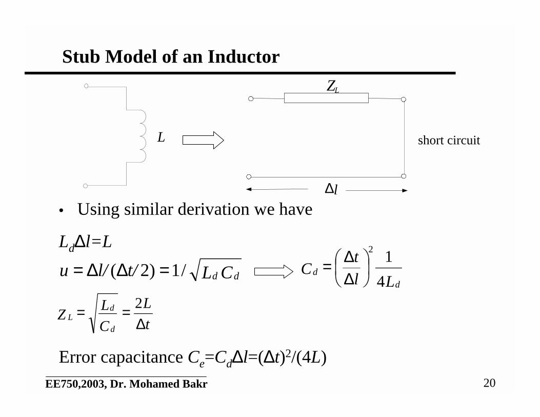
Stub Model of an Inductor
• Using similar derivation we have
Ld∆l=L
Error capacitance Ce=Cd∆l=(∆t)2/(4L)
CLt/l/u dd/1)2( =∆∆=Ll
tC
dd
4
12
∆∆=
t
L
C
LZ
d
dL ∆
== 2
L
Z
l∆
L
short circuit
21EE750,2003, Dr. Mohamed Bakr
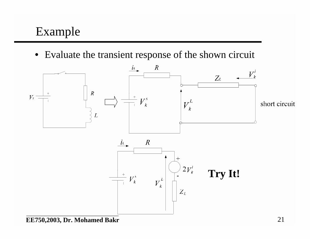
Example
• Evaluate the transient response of the shown circuit
Try It!
22EE750,2003, Dr. Mohamed Bakr
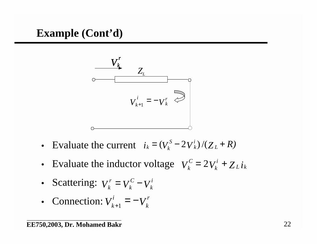
Example (Cont’d)
• Evaluate the current
• Evaluate the inductor voltage
• Scattering:
• Connection:
R)ZVVi Lik
Skk +−= /()2(
iZVV kLi
kCk += 2
VVV ik
Ck
rk −=
VV rk
ik
−=+1
VrkVrkVrkVr
ZL
VV rk
i
k−=+1