Embed Size (px)
Citation preview

EE586 Homework and Laboratory #6
Due November 17, 2010
1 | P a g e
There are 9 problems in this homework. Problem 8 is for graduate students only but undergraduate students can answer it for extra credit. Problem 9 is an OPNET problem on BGP. Maximum points for undergraduate: 20 points, and graduate students: 24 points 1. (2 pts, ch4, P.26) Consider the network shown below, and assume that each node
initially knows the costs to each of its neighbors. Consider the distance-vector algorithm and show the distance table entries at node z.
2. (3 pts, ch4, P.32) Consider the figure below.
Suppose there is another router w, connected to router y and z. The costs of all links are given as follows: c(x,y)=4,c(x,z)=50, c(y,w)=1,c(z,w)=1,c(y,z)=3. Suppose that poisoned reverse is used in the distance-vector routing algorithm.
a. When the distance vector routing is stabilized, router w, y, and z inform their distances to x to each other. What distance values do they tell each other?
b. Now suppose that the link cost between x and y increases to 60. Will there be a count-to-infinity problem even if poisoned reverse is used? Why or why not? If there is a count-to-infinity problem, then how many iterations are needed for the distance-vector routing to reach a stable state again? Justify your answer.
c. How do you modify c(y,z) such that there is no count-to-infinity problem at all if c(y,x) changes from 4 to 60?
3. (2 pts, ch4. P35) Consider the network shown below.

EE586 Homework and Laboratory #6
Due November 17, 2010
2 | P a g e
Suppose AS3 and AS2 are running OSPF for their intra-AS routing protocol. Suppose AS1 and AS4 are running RIP for their intra-AS routing protocol. Suppose eBGP and iBGP are used for the inter-AS routing protocol. Initially suppose there is no physical link between AS2 and AS4.
a. Router 3c learns about prefix x from which routing protocol: OSPF, RIP, eBGP, or iBGP?
b. Router 3a learns about x from which routing protocol? c. Router 1c learns about x from which routing protocol? d. Router 1d learns about x from which routing protocol?
4. (1 pt, Ch 5, P5) Consider the 7-bit generator, G=10011, and suppose that D has the
value 1010101010. What is the value of R? 5. (2 pts, Ch 5, P8) In Section 5.3, we provided an outline of the derivation of the
efficiency of slotted ALOHA. In this problem we’ll complete the derivation. a. Recall that when there are N active nodes, the efficiency of slotted
ALOHA is Np(1 – p)N–1. Find the value of p that maximizes this expression. b. Using the value of p found in (a), find the efficiency of slotted ALOHA by
letting N approach infinity. Hint: (1 – 1/N)N approaches 1/e as N approaches infinity.
6. (2 pts, Ch 5, modified P14)
Consider three LANs interconnected by two routers, as shown in the above figure. Let IPA to IPJ and MACA to MACJ be the IP and MAC addresses of the interfaces from A to J respectively.
a. Consider sending an IP datagram from Host E to Host B. Suppose all of the ARP tables are up to date. Enumerate all the steps, as done for the single-router example in Section 5.4.2.
G H
I J
EE586 Homework and Laboratory #6
Due November 17, 2010
3 | P a g e
b. Repeat (a), now assuming that the ARP table in the sending host is empty (and the other tables are up to date).
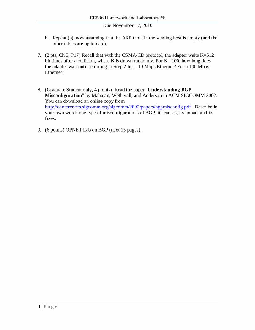
7. (2 pts, Ch 5, P17) Recall that with the CSMA/CD protocol, the adapter waits K=512
bit times after a collision, where K is drawn randomly. For K= 100, how long does the adapter wait until returning to Step 2 for a 10 Mbps Ethernet? For a 100 Mbps Ethernet?
8. (Graduate Student only, 4 points) Read the paper “Understanding BGP Misconfiguration” by Mahajan, Wetherall, and Anderson in ACM SIGCOMM 2002. You can download an online copy from http://conferences.sigcomm.org/sigcomm/2002/papers/bgpmisconfig.pdf . Describe in your own words one type of misconfigurations of BGP, its causes, its impact and its fixes.
9. (6 points) OPNET Lab on BGP (next 15 pages).
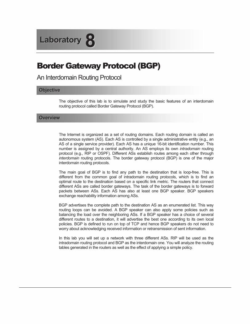
Border Gateway Protocol (BGP)
An Interdomain Routing Protocol
The objective of this lab is to simulate and study the basic features of an interdomain
routing protocol called Border Gateway Protocol (BGP).
The Internet is organized as a set of routing domains. Each routing domain is called an autonomous system (AS). Each AS is controlled by a single administrative entity (e.g., an AS of a single service provider). Each AS has a unique 16-bit identification number. This number is assigned by a central authority. An AS employs its own intradomain routing protocol (e.g., RIP or OSPF). Different ASs establish routes among each other through interdomain routing protocols. The border gateway protocol (BGP) is one of the major interdomain routing protocols.
The main goal of BGP is to find any path to the destination that is loop-free. This is different from the common goal of intradomain routing protocols, which is to find an optimal route to the destination based on a specific link metric. The routers that connect different ASs are called border gateways. The task of the border gateways is to forward packets between ASs. Each AS has also at least one BGP speaker. BGP speakers exchange reachability information among ASs.
BGP advertises the complete path to the destination AS as an enumerated list. This way routing loops can be avoided. A BGP speaker can also apply some policies such as balancing the load over the neighboring ASs. If a BGP speaker has a choice of several different routes to a destination, it will advertise the best one according to its own local policies. BGP is defined to run on top of TCP and hence BGP speakers do not need to worry about acknowledging received information or retransmission of sent information.
In this lab you will set up a network with three different ASs. RIP will be used as the intradomain routing protocol and BGP as the interdomain one. You will analyze the routing tables generated in the routers as well as the effect of applying a simple policy.
88LLaabboorraattoorryy
OObbjjeeccttiivvee
OOvveerrvviieeww

Read section 4.3 from "Computer Networks: A Systems Approach", 4
th Edition.
!Go to www.net-seal.net/animations.php and play the following animation:
- IP Subnets.
Create a New Project
1. Start OPNET IT Guru Academic Edition Choose New from the File menu.
2. Select Project and click OK Name the project <your initials>_BGP, and the
scenario No_BGP Click OK.
3. In the Startup Wizard: Initial Topology dialog box, make sure that Create Empty
Scenario is selected Click Next Select Campus from the Network Scale
list Click Next three times Click OK.
Create and Configure the Network
Initialize the Network:
1. The Object Palette dialog box should now be on top of your project workspace. If
it is not there, open it by clicking . Make sure that the internet_toolbox is
selected from the pull-down menu on the object palette.
2. Add to the project workspace the following objects from the palette: six
ethernet4_slip8_gtwy routers and two 100BaseT_LAN objects.
a. To add an object from a palette, click its icon in the object palette Move your
mouse to the workspace Click to place the object Right-click to stop
creating objects of that type.
3. Use bidirectional PPP_DS3 links to connect the routers you just added as in the
following figure. Also, rename the network objects as shown (right-click on the
node Set Name).
4. Use a bidirectional 100BaseT link to connect LAN_West to Router1 and another
100BaseT link to connect LAN_East to Router6 as in the following figure.
5. Close the Object Palette dialog box.
6. Save your project.
PPrroocceedduurree
The ethernet4_slip8_ gtwy node model represents an IP-based gateway supporting four Ethernet hub interfaces and eight serial line interfaces. IP packets arriving on any interface are routed to the appropriate output interface based on their destination IP address.
PPrreellaabb AAccttiivviittiieess

Routers Configuration:
1. Highlight or select simultaneously (using shift and left-click) all six routers
Right-click on any router Edit Attributes Check the Apply Changes to
Selected Objects check box.
2. Expand the BGP Parameters hierarchy and set the following:
i. Redistribution" Routing Protocols" RIP" Redistribute w/ Default.
3. Expand the IP Routing Parameters hierarchy and set the following:
i. Routing Table Export = Once at End of Simulation. This asks the router to
export its routing table at the end of the simulation to the simulation log.
4. Expand the RIP Parameters hierarchy and set the following:
i. Redistribution " Routing Protocols " Directly Connected "
Redistribute w/ Default.
5. Click OK and then save your project.
Application Configuration:
1. Right-click on LAN_West Edit Attributes Assign All to Application:
Supported Services Assign West_Server to the LAN Server Name attribute
as shown Click OK.
Notice that two objects for Applications and Profiles will be added automatically
to the project.
Redistribute w/ Default. allows a router to have a route to a destination that belongs to another Autonomous System

2. Right-click on LAN_East Edit Attributes:
i. Expand the Application: Supported Profiles hierarchy Set rows to 1
Expand the row 0 hierarchy Set Profile Name to E-commerce
Customer.
ii. Edit the Application: Destination Preferences attribute as follows:
Set rows to 1 Set Symbolic Name to HTTP Server Edit Actual Name
Set rows to 1 In the new row, assign West_ Server to the Name column.
3. Click OK three times and then save your project..
Configure the Simulation
Here we need to configure some of the simulation parameters:
1. Click on and the Configure Simulation window should appear.
2. Set the duration to be 10.0 minutes.
3. Click on the Global Attributes tab and make sure that the following attributes
are assigned as follows:

a. IP Interface Addressing Mode = Auto Addressed/Export.
b. IP Routing Table Export/Import = Export.
c. RIP Sim Efficiency = Disabled. If this attribute is enabled, RIP will stop
after the "RIP Stop Time." But we need the RIP to keep updating the
routing table in case there is any change in the network.
4. Click OK and then save the project.
Choose the Statistics
1. Right-click on LAN_East and select Choose Individual Statistics from the pop-
up menu From the Client HTTP hierarchy choose the Traffic Received
(bytes/sec) statistic Click OK.
2. Right-click on the link that connects Router2 to Router3 and select Choose
Individual Statistics from the pop-up menu From the point-to-point
hierarchy choose the “Throughput (bits/sec) -->” statistic Click OK.
Note: If the name of the link is “Router3 <-> Router2” then you will need to choose the “Throughput (bits/sec) <--” statistic instead.
3. Right-click on the link that connects Router2 to Router4 and select Choose
Individual Statistics from the pop-up menu From the point-to-point
hierarchy choose the “Throughput (bits/sec) -->” statistic Click OK.
Note: If the name of the link is “Router4 <-> Router2” then you will need to choose the “Throughput (bits/sec) <--” statistic instead.
4. Save your project.
Auto Addressed means that all IP interfaces are assigned IP addresses automatically during simulation. The class of address (e.g., A, B, or C) is determined based on the number of hosts in the designed network. Subnet masks assigned to these interfaces are the default subnet masks for that class.
Export causes the auto-assigned IP interface to be exported to a file (name of the file is <net_name>-ip_addresses.gdf and gets saved in the primary model directory).

Router Interfaces and IP Addresses
Before setting up the routers to use BGP, we need to get the information of the routers’
interfaces along with the IP addresses associated to these interfaces. Recall that these IP
addresses are assigned automatically during simulation, and we set the global attribute IP
Interface Addressing Mode to export this information to a file.
1. First we need to run the simulation. Click on and the Configure Simulation
window should appear Click on Run.
2. After the simulation run completes click Close.
3. From the File menu choose Model Files Refresh Model Directories. This
causes OPNET IT Guru to search the model directories and update its list of files.
4. From the File menu choose Open From the drop-down menu choose Generic
Data File Select the <<your initials>_BGP-No_BGP -ip_addresses file
Click OK.
The file that contains all the information about router interfaces and their IP addresses will
open. Table 1 shows the interface number and IP addresses between the six outers in our
projects. For example Router1 is connected to Router2 through interface (IF) 11, which is
assigned 192.0.1.1 as its IP address. A router is connected to itself by a Loopback
interface as shown. Create a similar table for your project but note that your result may
vary due to different nodes placement.
Routers 1 2 3 4 5 6
1IF: 12
IP: 192.0.2.1
IF: 11
IP: 192.0.1.1
2IF: 10
IP: 192.0.1.2
IF: 12
IP: 192.0.8.1
IF: 11
IP: 192.0.4.2
IF: 4
IP: 192.0.7.1
3IF: 10
IP: 192.0.4.1
IF: 12
IP: 192.0.6.1
IF: 11
IP: 192.0.5.1
IF: 4
IP: 192.0.3.1
4IF: 10
IP: 192.0.7.2
IF: 11
IP: 192.0.5.2
IF: 12
IP: 192.0.10.1
IF: 4
IP: 192.0.9.1
5IF: 10
IP: 192.0.3.2
IF: 11
IP: 192.0.9.2
IF: 12
IP: 192.0.12.1
IF: 4
IP: 192.0.11.1
6 IF: 10
IP: 192.0.11.2
IF: 12
IP: 192.0.14.1
Table 1: Interfaces that connect the routers and their assigned IP addresses

Creating the BGP Scenario
In the network we just created, all routers belong to the same autonomous system. We will
divide the network into three autonomous systems and utilize BGP to route packets
among these systems.
1. Select Duplicate Scenario from the Scenarios menu and name it BGP_Simple
Click OK.
2. Highlight or select simultaneously (using shift and left-click) Router1 and Router2
Right-click on Router1 Edit Attributes Check the Apply Changes to
Selected Objects check box.
3. Expand the IP Routing Parameters hierarchy and set the Autonomous System
Number to 12 Click OK.
4. Repeat steps 2 and 3 above for routers Router3 and Router4. Assign their
Autonomous System Number to 34.
5. Repeat steps 2 and 3 above for routers Router5 and Router6. Assign their
Autonomous System Number to 56.
The following figure shows the created autonomous systems. The figure shows also the interfaces that connect routers across different autonomous systems. There interfaces are taken from Table 1 above (note: the interface numbers in your project may vary). The next step is to disable the RIP protocol on the shown interfaces.
AS 34AS 12
AS 5611
4
10 4
104
10
11

6. Right-click on Router2 Edit Attributes Expand the IP Routing
Parameters hierarchy Expand the Interface Information hierarchy Expand
row 4 hierarchy Click on the values of the Routing Protocol(s) attribute
Disable RIP as shown click OK twice.
7. Repeat step 6 above for all other interfaces that connect routers across autonomous systems (i.e., All the eight inter-domain interfaces shown above).
8. Save your project.
Configuring the BGP Neighbor Information
If you try to run the simulation of the BGP_Simple scenario, you will receive hundreds of
errors! This is because there is no routing protocol running between the inter-domain
routers. Therefore, no routing tables are created to deliver packets among autonomous
systems. The solution is to utilize BGP by defining the neighbors of inter-domain routers.
Table 2 shows the neighbors of the routers that will run BGP. Neighbors are defined by
their interface IP address and the AS number. For each router in Table 2 carry out the
following step:
1. Right-click on the router Edit Attributes Expand the BGP Parameters
hierarchy Expand the Neighbor Information hierarchy Assign to the rows
attribute the value 1 for Router1 and Router6. For all other routers, assign the
value 3 to the rows attribute Utilize Table 2 to assign the corresponding values
to the IP Address, Remote AS, and Update Source attributes for each of the
added rows.

Note: the values to be assigned to the IP Address attribute have to match the
values you will collect in your Table 1.
2. Save your project.
BGP Parameters Neighbor Information Routers
row 0 row 1 row 2
Router1
IP Address: 192.0.8.1
Remote AS: 12
Update Source: Loopback
Router2
IP Address: 192.0.4.1
Remote AS: 34
Update Source: Not Used
IP Address: 192.0.7.2
Remote AS: 34
Update Source: Not Used
IP Address: 192.0.2.1
Remote AS: 12
Update Source: Loopback
Router3
IP Address: 192.0.4.2
Remote AS: 12
Update Source: Not Used
IP Address: 192.0.3.2
Remote AS: 56
Update Source: Not Used
IP Address: 192.0.10.1
Remote AS: 34
Update Source: Loopback
Router4
IP Address: 192.0.7.1
Remote AS: 12
Update Source: Not Used
IP Address: 192.0.9.2
Remote AS: 56
Update Source: Not Used
IP Address: 192.0.6.1
Remote AS: 34
Update Source: Loopback
Router5
IP Address: 192.0.3.1
Remote AS: 34
Update Source: Not Used
IP Address: 192.0.9.1
Remote AS: 34
Update Source: Not Used
IP Address: 192.0.14.1
Remote AS: 56
Update Source: Loopback
Router6
IP Address: 192.0.12.1
Remote AS: 56
Update Source: Loopback
Table 2: Neighbors’ info for inter-domain routers
Creating the BGP with Policy Scenario
BGP allows for routing policies that can be enforced using route maps. We will utilize this
feature to configure Router2 to redirect its load on the two egress links of its autonomous
system.
1. First make sure that your project is in the BGP_Simple scenario. Select
Duplicate Scenario from the Scenarios menu and name it BGP_Policy Click
OK.
2. Right-click on Router2 Edit Attributes Expand the IP Routing
Parameters hierarchy Expand the Route Map Configuration hierarchy
Set the attributes as shown in the following figure.
The purpose of the created route map is to reduce the degree of preference of
the “route to AS 56” to the value 10 (Note: the normal value is "99", which is
calculated as 100 - number of AS that should be crossed to reach the
destination).

The next step is to assign the above route map to the link connecting Router2 to Router3.
This way traffic from Router2 to AS 56 will be preferred to go through Router4 instead.
3. Right-click on Router2 Edit Attributes Expand the BGP Parameters
hierarchy Expand the Neighbor Information hierarchy Expand the row that
has the IP address of Router3 interface (it is row 0 in my project) Expand the
Routing Policies hierarchy Set its attribute as shown in the following figure.
4. Click OK and save your project.

Run the Simulation
To run the simulation for the three scenarios simultaneously:
1. Go to the Scenarios menu Select Manage Scenarios.
2. Change the values under the Results column to <collect> (or <recollect>)
for the three scenarios. Compare to the following figure.

3. Click OK to run the three simulations. Depending on the speed of your
processor, this may take several minutes to complete.
4. After the three simulation runs complete, one for each scenario, click Close
Save your project.
View the Results
Compare the Routing Tables Content:
1. To check the content of the routing tables in Router2 for both scenarios:
i. Go to the Results menu Open Simulation Log Expand the hierarchy
on the left as shown below Click on the field COMMON ROUTE TABLE in
the row corresponds to Rouer2.
2. Carry out the previous step for scenario No_BGP and scenario BGP_Simple.
The following are partial contents of Router2’s routing table for both scenarios
(Note: Your results may vary due to different nodes placement):
Routing table of Router2 for the No_BGP scenario:

Routing table of Router2 for the BGP_Simple scenario:
Compare the load in the network:
1. Select Compare Results from the Results menu.
2. Change the drop-down menu in the right-lower part of the Compare Results
dialog box from As Is to time_average as shown.
3. Select and show the graphs of the following statistics: Traffic Received in
LAN_East, throughput in the Router2-Router3 link, and throughput in the
Router2-Router4 link. The resulting graphs should resemble the graphs below.


! A Border Gateway Protocol 4 (BGP-4): IETF RFC number 1771
(www.ietf.org/rfc.html).
! Application of the Border Gateway Protocol in the Internet: IETF RFC number
1772 (www.ietf.org/rfc.html).
! BGP-4 Protocol Analysis: IETF RFC number 1774 (www.ietf.org/rfc.html).
1) Obtain and analyze the routing table for Router5 in the project before and after
applying BGP.
2) Analyze the graphs that show the throughput in both Router2-Router3 link and
Router2-Router4 link. Explain the effect of applying the routing policy on these
throughputs.
3) Create another scenario as a duplicate of the BGP_Simple scenario. Name the
new scenario BGP_OSPF_RIP. In this new scenario change the intradomain
routing protocol in AS 56 to be OSPF instead of RIP. Run the new scenario and
check the contents of Router5‘s routing table. Analyze the content of this table.
Prepare a report that follows the guidelines explained in Lab 0. The report should include
the answers to the above exercises as well as the graphs you generated from the
simulation scenarios. Discuss the results you obtained and compare these results with
your expectations. Mention any anomalies or unexplained behaviors.
FFuurrtthheerr RReeaaddiinnggss
EExxeerrcciisseess
LLaabb RReeppoorrtt