Embed Size (px)
DESCRIPTION
ppt
Citation preview

EE2351 R.KALAIVANI AP/EEE 1
EE2351POWER SYSTEM ANALYSIS
R.KALAIVANI
EEE DEPARTMENT
www.Vidyarthiplus.com

EE2351 R.KALAIVANI AP/EEE 2
UNIT I
INTRODUCTION
EE2351 R.KALAIVANI AP/EEE 3
Power system network

EE2351 R.KALAIVANI AP/EEE 4
SINGLE LINE DIAGRAM
It is a diagrammatic representation of a power system in
which the components are represented by their symbols.

EE2351 R.KALAIVANI AP/EEE 5
COMPONENTS OF A POWER SYSTEM
1.Alternator
2.Power transformer
3.Transmission lines
4.Substation transformer
5.Distribution transformer
6.Loads

EE2351 R.KALAIVANI AP/EEE 6
MODELLING OF GENERATOR AND SYNCHRONOUS MOTOR
1Φ equivalent circuit of generator 1Φ equivalent circuit of synchronous motor
EE2351 R.KALAIVANI AP/EEE 7
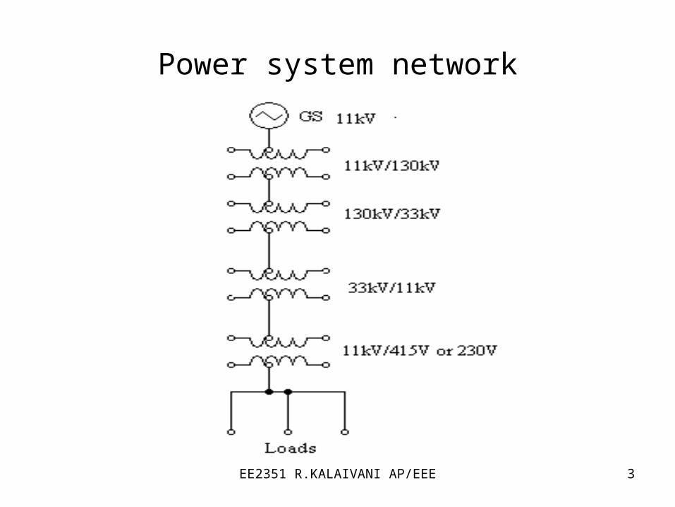
MODELLING OF TRANSFORMER
2 2 1
1 1 2
' 201 1 2 1 2
' 201 1 2 1 2
E N IK
E N I
RR R R R
KX
X X X XK
=Equivalent resistance referred to 1o
=Equivalent reactance referred to 1o

EE2351 R.KALAIVANI AP/EEE 8
MODELLING OF TRANSMISSION LINE
Π type T type

EE2351 R.KALAIVANI AP/EEE 9
MODELLING OF INDUCTION MOTOR
'
'
'
1( 1)r
S r
S r
Rs
R R R
X X X
=Resistance representing load
=Equivalent resistance referred to stator
=Equivalent reactance referred to stator
EE2351 R.KALAIVANI AP/EEE 10
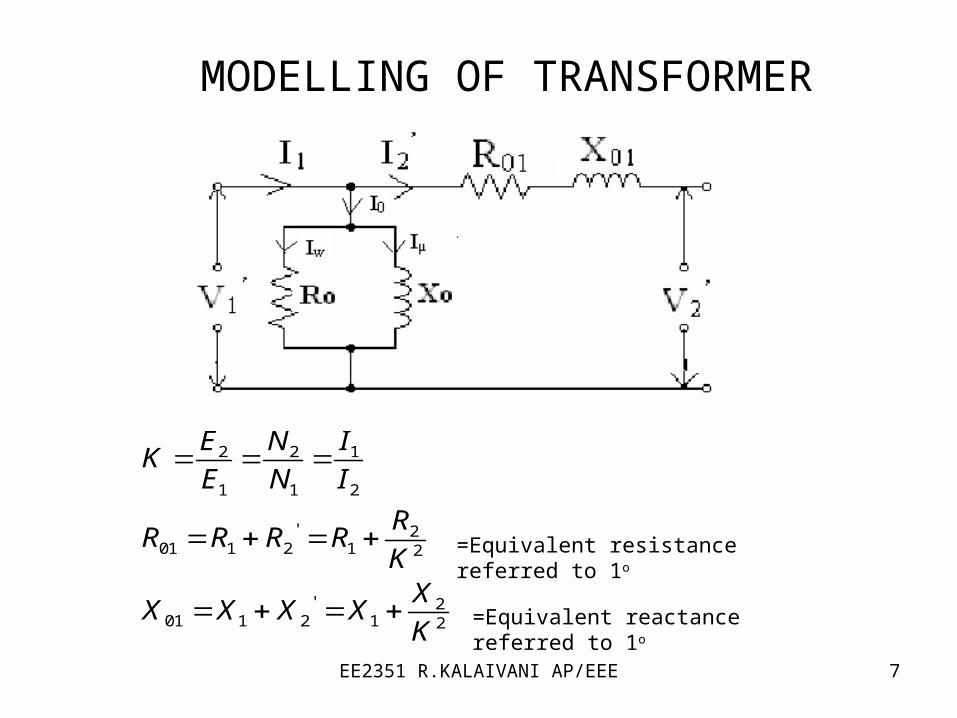
2 2
1000
b bb
bb
kV kVZ
KVAMVA
per unit=actual value/base value
Let KVAb=Base KVA
kVb=Base voltage
Zb=Base impedance in Ω

EE2351 R.KALAIVANI AP/EEE 11
Changing the base of per unit quantities
Let z = actual impedance(Ω)
= base impedance (Ω)
bZ
. 2 2
* bp u
b b b
b
Z MVAZ ZZ
Z kV kV
MVA
Let , ,
, ,
&
&b old b old
b new b new
kV MVB
kV MVB
represent old base values
represent new base values

EE2351 R.KALAIVANI AP/EEE 12
,. , 2
,
. , ,
2
,
,. , 2
,
2
, ,. , . , 2
,,
*(1)
*(2)
*(3)
* *
b oldp u old
b old
p u old b old
b old
b newp u new
b new
b old b newp u new p u old
b oldb new
Z MVAZ
kV
Z MVAZ
kV
Z MVAZ
kV
kV MVAZ Z
MVAkV

EE2351 R.KALAIVANI AP/EEE 13
ADVANTAGES OF PER UNIT CALCULATIONS
The p.u impedance referred to either side of a 1Φ transformer is same
The manufacturers provide the impedance value in p.u The p.u impedance referred to either side of a 3Φ
transformer is same regardless of the 3Φ connections Y-Y,Δ-Y
p.u value always less than unity.
EE2351 R.KALAIVANI AP/EEE 14
IMPEDANCE DIAGRAM
• This diagram obtained by replacing each component by their 1Φ equivalent circuit.
Following approximations are made to draw impedance diagram
1. The impedance b/w neutral and ground omitted.
2. Shunt branches of the transformer equivalent circuit
neglected.

EE2351 R.KALAIVANI AP/EEE 15
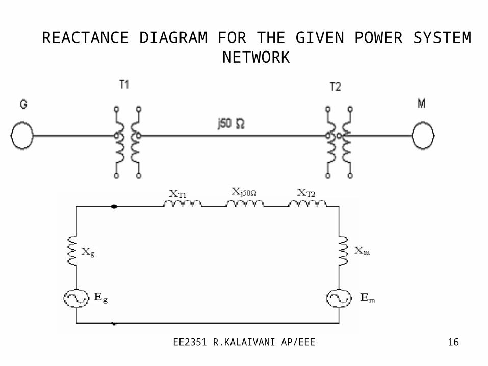
REACTANCE DIAGRAM
It is the equivalent circuit of the power system in which the various components are represented by their respective equivalent circuit.
Reactance diagram can be obtained after omitting all
resistances & capacitances of the transmission line from
impedance diagram
EE2351 R.KALAIVANI AP/EEE 16
REACTANCE DIAGRAM FOR THE GIVEN POWER SYSTEM NETWORK

EE2351 R.KALAIVANI AP/EEE 17
PROCEDURE TO FORM REACTANCE DIAGRAM FROM SINGLE DIAGRAM
1.Select a base power kVAb or MVAb
2.Select a base voltage kVb
3. The voltage conversion is achieved by means of transformer kVb on LT section= kVb on HT section x LT voltage rating/HT voltage rating
4. When specified reactance of a component is in ohms
p.u reactance=actual reactance/base reactance
specified reactance of a component is in p.u
2
, ,. , . , 2
,,
* *b old b newp u new p u old
b oldb new
kV MVAX X
MVAkV
EE2351 R.KALAIVANI AP/EEE 18
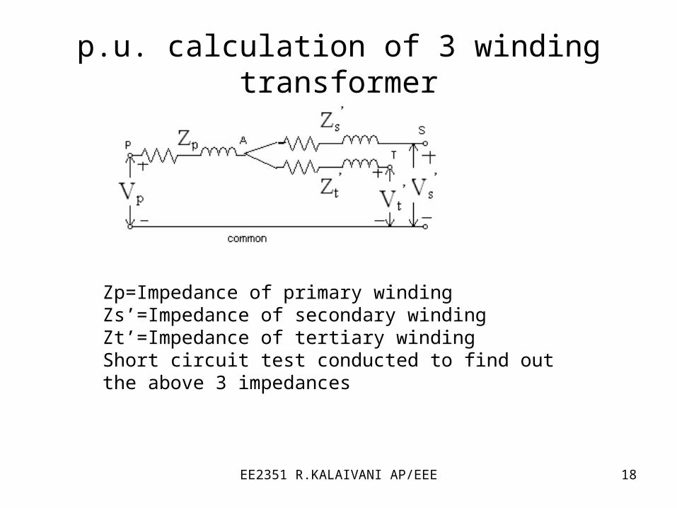
p.u. calculation of 3 winding transformer
Zp=Impedance of primary windingZs’=Impedance of secondary windingZt’=Impedance of tertiary windingShort circuit test conducted to find out the above 3 impedances
EE2351 R.KALAIVANI AP/EEE 19
'
' '
' '
1
21
21
2
p ps pt st
s ps st pt
t ps pt st
Z Z Z Z
Z Z Z Z
Z Z Z Z
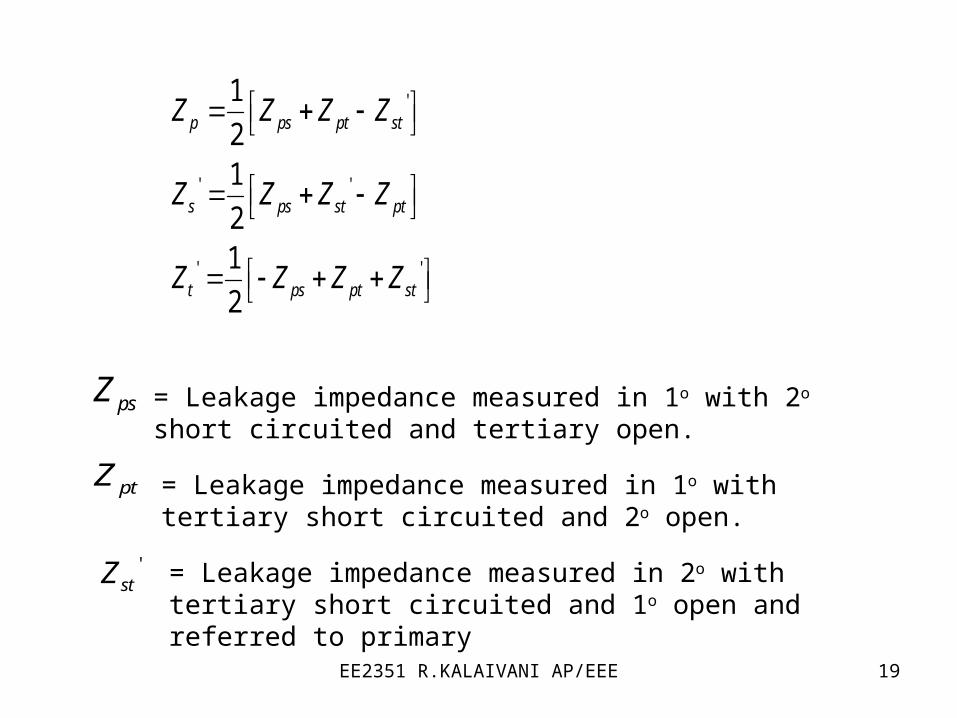
psZ
ptZ
= Leakage impedance measured in 1o with 2o short circuited and tertiary open.
= Leakage impedance measured in 1o with tertiary short circuited and 2o open.
'stZ = Leakage impedance measured in 2o with tertiary short
circuited and 1o open and referred to primary
EE2351 R.KALAIVANI AP/EEE 20
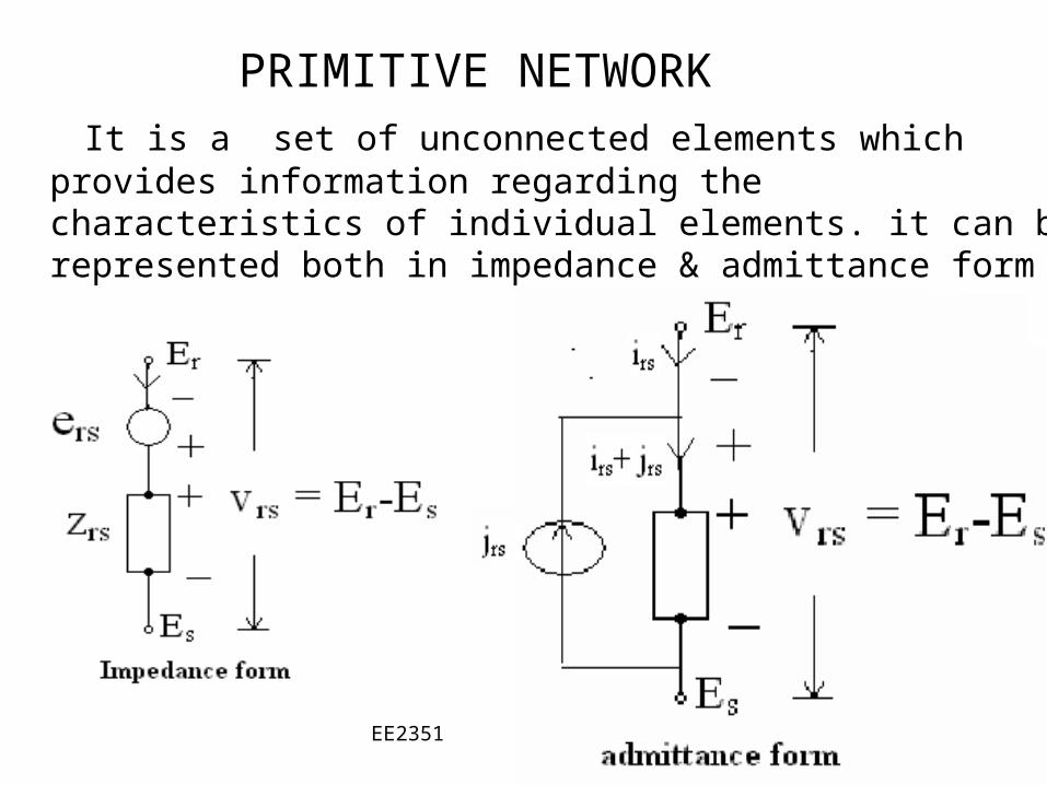
PRIMITIVE NETWORK It is a set of unconnected elements which provides information
regarding the characteristics of individual elements. it can be represented both in impedance & admittance form

EE2351 R.KALAIVANI AP/EEE 21
BUS ADMITTANCE(Y BUS) MATRIX
Y BUS can be formed by 2 methods
1.Inspection method
2.Singular transformation
Y BUS = 11 12 1
21 22 2
1 2
n
n
n n nn
Y Y Y
Y Y Y
Y Y Y

EE2351 R.KALAIVANI AP/EEE 22
INSPECTION METHOD
For n bus system
Diagonal element of Y BUS
Off Diagonal element of Y BUS
ij ijY y
1
n
ii ijj
Y y

EE2351 R.KALAIVANI AP/EEE 23
SINGULAR TRANSFORMATION METHOD
Y BUS =
Where [y]=primitive admittance
A=bus incidence matrix
TA y A

EE2351 R.KALAIVANI AP/EEE 24
ALGORITHM FOR FORMATION OF THE BUS IMPEDANCE MATRIX
• Modification of Zbus matrix involves any one of the following 4 cases
Case 1:adding a branch impedance zb from a new bus p to the reference bus
Addition of new bus will increase the order the Zbus matrix by 1
(n+1)th column and row elements are zero except the diagonal
diagonal element is zb
,
0
0original
bus newb
zZ
z

EE2351 R.KALAIVANI AP/EEE 25
Case 2: adding a branch impedance zb from a new bus p
to the existing bus q
Addition of new bus will increase the order the Zbus matrix by 1
The elements of (n+1)th column and row are the elements of
qth column and row and the diagonal element is Zqq+Zb
Case 3:adding a branch impedance zb from an existing bus p to
the reference bus
The elements of (n+1)th column and row are the elements of
qth column and row and the diagonal element is Zqq+Zb and
(n+1)th row and column should be eliminated using the following
formula
( 1) ( 1),
( 1)( 1)
1,2... ; 1, 2..j n n kjk act jk
n n
Z ZZ Z j n k n
Z

EE2351 R.KALAIVANI AP/EEE 26
Case 4:adding a branch impedance zb between existing buses h and q
elements of (n+1)th column are elements of bus h column –
bus q column and elements of (n+1)th row are elements of
bus h row – bus q row the diagonal element=
and (n+1)th row and column should be eliminated using the following
formula
2b hh qq hqZ Z Z Z
( 1) ( 1),
( 1)( 1)
1,2... ; 1, 2..j n n kjk act jk
n n
Z ZZ Z j n k n
Z

EE2351 R.KALAIVANI AP/EEE 27
UNIT II
POWER FLOW ANALYSIS

EE2351 R.KALAIVANI AP/EEE 28
BUS CLASSIFICATION
1.Slack bus or Reference bus or Swing bus:
|V| and δ are specified. P and Q are un specified, and to be calculated.
2.Generator bus or PV bus or Voltage controlled bus:
P and |V| are specified. Q and δ are un specified, and to be calculated
3.Load bus or PQ bus:
P and Q are specified. |V| and δ are un specified, and to be
calculated

EE2351 R.KALAIVANI AP/EEE 29
ITERATIVE METHOD
The above Load flow equations are non linear and can be solved by following iterative methods.
1.Gauss seidal method2.Newton Raphson method
3.Fast Decoupled method
1
*
*1
n
p pq qq
p p p P p
np p
pq qqP
I Y V
S P jQ V I
P jQY V
V

EE2351 R.KALAIVANI AP/EEE 30
GAUSS SEIDAL METHOD
For load bus calculate |V| and δ from Vpk+1 equation
For generator bus calculate Q from QPK+1 equation
11 * 1
1
1*Im ( )p n
k k k kp P pq q pq q
q q p
Q V Y V Y V
11 1
*1 1
1
( )
p np pk k k
p pq q pq qkq q ppp P
P jQV Y V Y V
Y V

EE2351 R.KALAIVANI AP/EEE 31
• Check Qp,calk+1 with the limits of Qp
• If Qp,calk+1 lies within the limits bus p remains as PV bus
otherwise it will change to load bus• Calculate δ for PV bus from Vp
k+1 equation• Acceleration factor α can be used for faster convergence
• Calculate change in bus-p voltage
• If |ΔVmax |< ε, find slack bus power otherwise increase the iteration count (k)
• Slack bus power=
1 1k k kp p pV V V
G LS S
EE2351 R.KALAIVANI AP/EEE 32
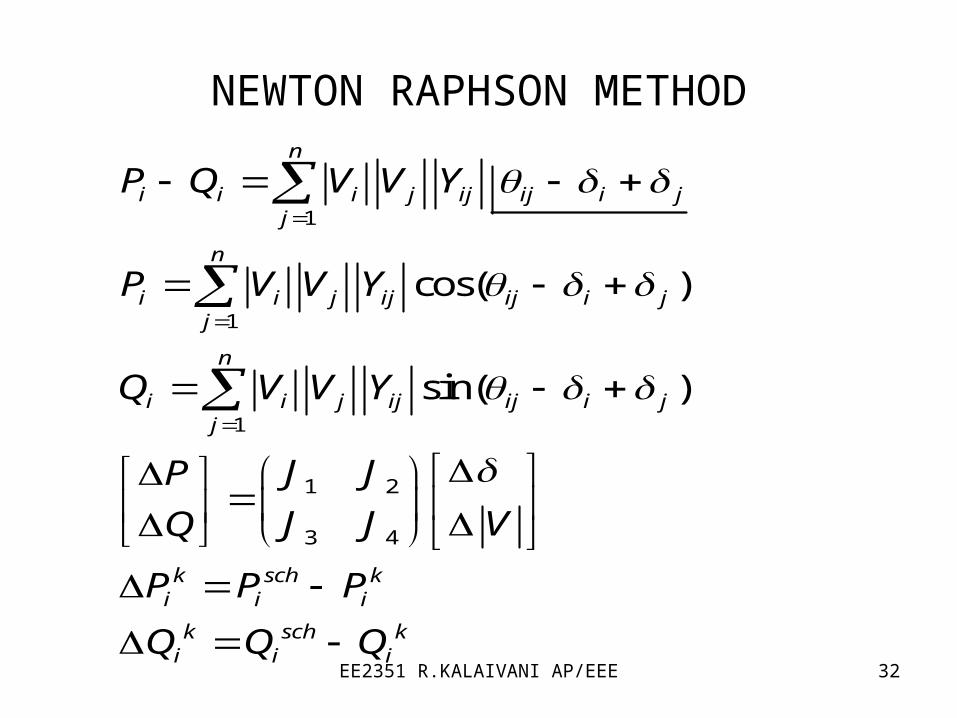
NEWTON RAPHSON METHOD
1
1
1
1 2
3 4
cos( )
sin( )
n
i i i j ij ij i jj
n
i i j ij ij i jj
n
i i j ij ij i jj
k sch ki i i
k sch ki i i
P Q V V Y
P V V Y
Q V V Y
J JP
J J VQ
P P P
Q Q Q

EE2351 R.KALAIVANI AP/EEE 33
• Calculate |V| and δ from the following equation
• If
• stop the iteration otherwise increase the iteration count (k)
1
1
k k ki i
k k ki i iV V V
ki
ki
P
Q

EE2351 R.KALAIVANI AP/EEE 34
FAST DECOUPLED METHOD
J2 & J3 of Jacobian matrix are zero1
4
1
4
'
''
1'
1''
0
0
i
i
JP
VJQ
PP J
QQ J V V
V
PB
V
QB V
V
PB
V
QV B
V

EE2351 R.KALAIVANI AP/EEE 35
1
1
k k ki i
k k ki i iV V V
This method requires more iterations than NR
method but less time per iteration
It is useful for in contingency analysis

EE2351 R.KALAIVANI AP/EEE 36
COMPARISION BETWEEN ITERATIVE METHODS
Gauss – Seidal Method
1. Computer memory requirement is less.
2. Computation time per iteration is less.
3. It requires less number of arithmetic operations to complete an iteration and ease in programming.
4. No. of iterations are more for convergence and rate of convergence is slow (linear convergence characteristic.
5. No. of iterations increases with the increase of no. of buses.

EE2351 R.KALAIVANI AP/EEE 37
NEWTON – RAPHSON METHOD
Superior convergence because of quadratic convergence. It has an 1:8 iteration ratio compared to GS method. More accurate. Smaller no. of iterations and used for large size systems. It is faster and no. of iterations is independent of the no. of buses. Technique is difficult and calculations involved in each iteration are
more and thus computation time per iteration is large. Computer memory requirement is large, as the elements of jacobian
matrix are to be computed in each iteration. Programming logic is more complex.
EE2351 R.KALAIVANI AP/EEE 38
FAST DECOUPLED METHOD
It is simple and computationally efficient. Storage of jacobian matrix elements are60% of NR
method computation time per iteration is less. Convergence is geometric,2 to 5 iterations required for
accurate solutions Speed for iterations is 5 times that of NR method and 2-3
times of GS method
EE2351 R.KALAIVANI AP/EEE 39
UNIT III
FAULT ANALYSIS-BALANCED FAULT

EE2351 R.KALAIVANI AP/EEE 40
Need for fault analysis To determine the magnitude of fault current throughout
the power system after fault occurs. To select the ratings for fuses, breakers and switchgear. To check the MVA ratings of the existing circuit breakers
when new generators are added into a system.
EE2351 R.KALAIVANI AP/EEE 41
BALANCED THREE PHASE FAULT
All the three phases are short circuited to each other and to earth. Voltages and currents of the system balanced after the symmetrical fault
occurred. It is enough to consider any one phase for analysis.
SHORT CIRCUIT CAPACITY
It is the product of magnitudes of the prefault voltage and the post fault current. It is used to determine the dimension of a bus bar and the interrupting capacity of a circuit breaker.

EE2351 R.KALAIVANI AP/EEE 42
Short Circuit Capacity (SCC)0
2
,1
1.
,3
3.
6
3
6,
/
*10
3 * *10
F
TF
T
bT
T T p u
b
T p u
f
L b
SCC V I
VI
Z
SVSCC MVA
Z Z
SSCC MVA
Z
SCCI
V
EE2351 R.KALAIVANI AP/EEE 43
Procedure for calculating short circuit capacity and fault current
Draw a single line diagram and select common base Sb MVA and kV
Draw the reactance diagram and calculate the total p.u impedance from the fault point to source (Thevenin impedance ZT)
Determine SCC and If

EE2351 R.KALAIVANI AP/EEE 44
ALGORITHM FOR SHORT CIRCUIT ANALYSIS USING BUS IMPEDANCE MATRIX
• Consider a n bus network. Assume that three phase fault
is applied at bus k through a fault impedance zf
• Prefault voltages at all the buses are
• Draw the Thevenin equivalent circuit i.e Zeroing all voltage sources and add voltage source at faulted bus k and draw the reactance diagram
1
2
(0)
(0)
.(0)
(0)
.
(0)
busk
n
V
V
VV
V
(0)kV
EE2351 R.KALAIVANI AP/EEE 45
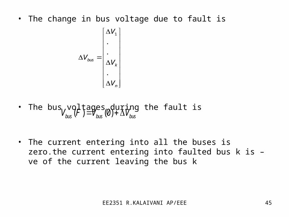
• The change in bus voltage due to fault is
• The bus voltages during the fault is
• The current entering into all the buses is zero.the current entering into faulted bus k is –ve of the current leaving the bus k
1
.
.
.
busk
n
V
VV
V
( ) (0)bus bus busV F V V

EE2351 R.KALAIVANI AP/EEE 46
11 1 1
1
1
. . 0
. . . . . .
. . ( )
. . . . . .
. . 0
( ) (0) ( )
( ) ( )
(0)( )
( ) (0) ( )
bus bus bus
k n
bus k kk kn k
n nk nn
k k kk k
k f k
kk
kk f
i i ik k
V Z I
Z Z Z
V Z Z Z I F
Z Z Z
V F V Z I F
V F Z I F
VI F
Z Z
V F V Z I F

EE2351 R.KALAIVANI AP/EEE 47
UNIT IV
FAULT ANALYSIS – UNBALANCED FAULTS

EE2351 R.KALAIVANI AP/EEE 48
INTRODUCTION
UNSYMMETRICAL FAULTSo One or two phases are involvedo Voltages and currents become unbalanced and each phase is to be
treated individuallyo The various types of faults are Shunt type faults 1.Line to Ground fault (LG) 2. Line to Line fault (LL) 3. Line to Line to Ground fault (LLG) Series type faults Open conductor fault (one or two conductor open fault)
EE2351 R.KALAIVANI AP/EEE 49
FUNDAMENTALS OF SYMMETRICAL COMPONENTS
Symmetrical components can be used to transform
three phase unbalanced voltages and currents to
balanced voltages and currents Three phase unbalanced phasors can be resolved into
following three sequences
1.Positive sequence components
2. Negative sequence components
3. Zero sequence components
EE2351 R.KALAIVANI AP/EEE 50
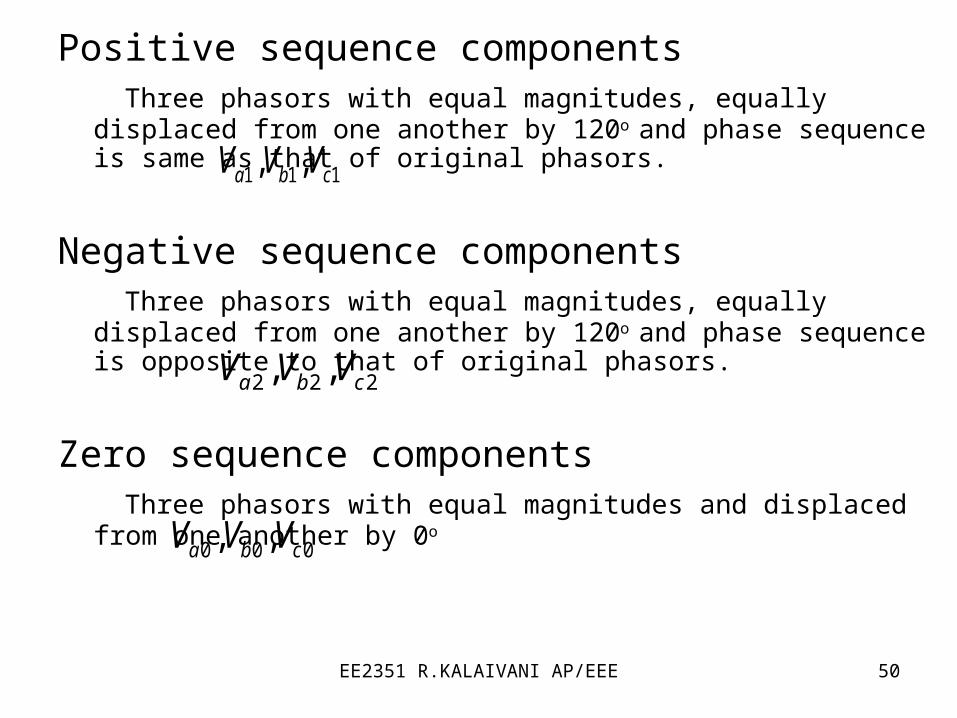
Positive sequence components Three phasors with equal magnitudes, equally displaced from one
another by 120o and phase sequence is same as that of original phasors.
Negative sequence components Three phasors with equal magnitudes, equally displaced from one
another by 120o and phase sequence is opposite to that of original phasors.
Zero sequence components Three phasors with equal magnitudes and displaced from one another
by 0o
1 1 1, ,a b cV V V
2 2 2, ,a b cV V V
0 0 0, ,a b cV V V

EE2351 R.KALAIVANI AP/EEE 51
RELATIONSHIP BETWEEN UNBALANCED VECTORS AND SYMMETRICAL COMPONENTS
0 1 2
0 1 2
0 1 2
0
21
22
2
2
1 1 1
1
1
1 1 1
1
1
a a a a
b b b b
c c c c
a a
b a
c a
V V V V
V V V V
V V V V
V V
V a a V
a aV V
A a a
a a
Similarly we can obtain for currents also

EE2351 R.KALAIVANI AP/EEE 52
SEQUENCE IMPEDANCE
Impedances offered by power system components to positive, negative and zero sequence currents.
Positive sequence impedance The impedance of a component when positive sequence
currents alone are flowing.
Negative sequence impedance The impedance of a component when negative sequence
currents alone are flowing.
Zero sequence impedance The impedance of a component when zero sequence currents
alone are flowing.

EE2351 R.KALAIVANI AP/EEE 53
SEQUENCE NETWORK
SEQUENCE NETWORK FOR GENERATOR
positive sequence network negative sequence network Zero sequence network

EE2351 R.KALAIVANI AP/EEE 54
SEQUENCE NETWORK FOR TRANSMISSION LINE
positive sequence network negative sequence network Zero sequence network

EE2351 R.KALAIVANI AP/EEE 55
SEQUENCE NETWORK FOR TRANSFORMER
positive sequence network negative sequence network Zero sequence network
EE2351 R.KALAIVANI AP/EEE 56
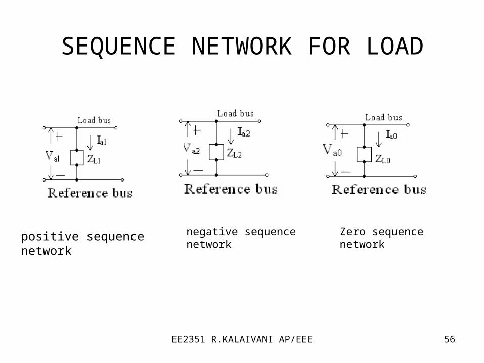
SEQUENCE NETWORK FOR LOAD
positive sequence network negative sequence network Zero sequence network

EE2351 R.KALAIVANI AP/EEE 57
SINGLE LINE TO GROUND FAULT
b
c
fa a
a1 a2 a0 a
a11 2 0
I 0
I 0
V Z I
I I I I / 3
I3
af
E
Z Z Z Z
Consider a fault between phase a and
ground through an impedance zf
EE2351 R.KALAIVANI AP/EEE 58
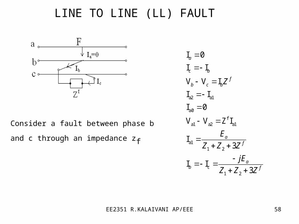
LINE TO LINE (LL) FAULT
a2 a1
a0
fa1 a2 a1
a11 2
1 2
I 0
I I
V V I
I I
I 0
V V Z I
I3
I I3
a
c b
fb c b
af
ab c f
Z
E
Z Z Z
jE
Z Z Z
Consider a fault between phase b and c
through an impedance zf
EE2351 R.KALAIVANI AP/EEE 59
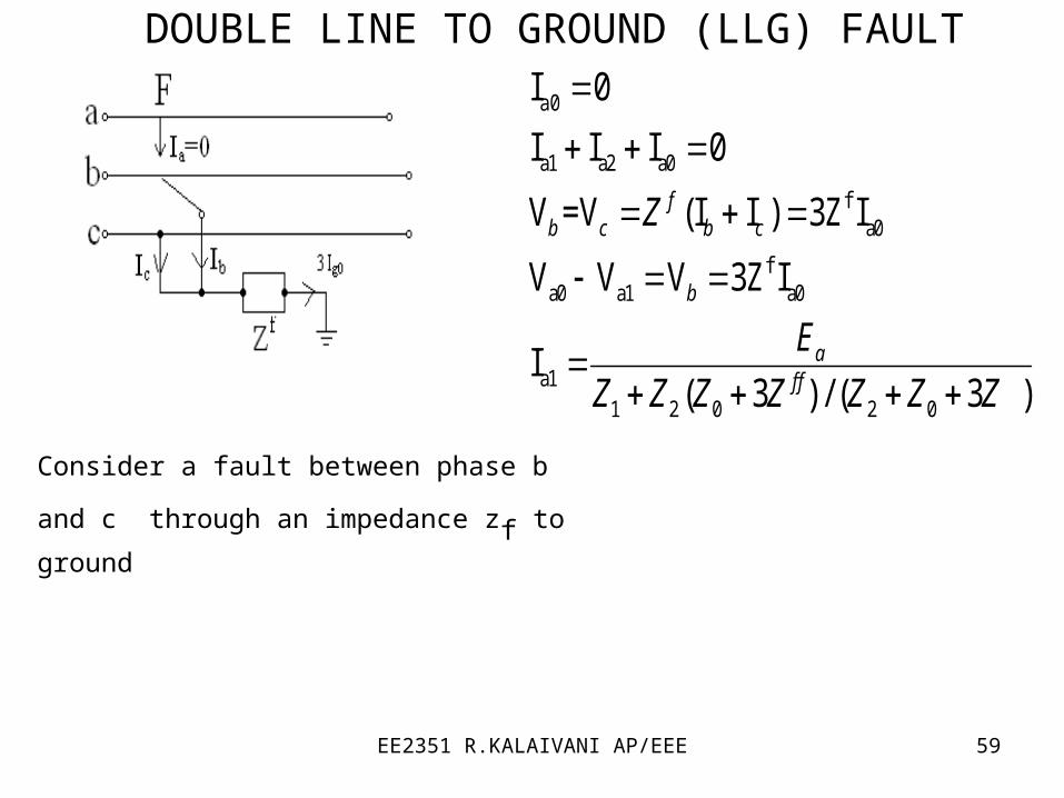
DOUBLE LINE TO GROUND (LLG) FAULT
a0
a1 a2 a0
fa0
fa0 a1 a0
a11 2 0 2 0
I 0
I I I 0
V =V (I I ) 3Z I
V V V 3Z I
I( 3 ) / ( 3 )
fb c b c
b
af f
Z
E
Z Z Z Z Z Z Z
Consider a fault between phase b and c
through an impedance zf to ground
EE2351 R.KALAIVANI AP/EEE 60
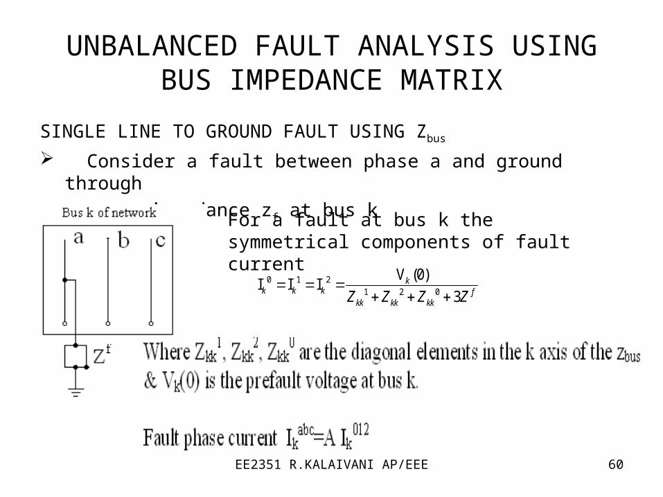
UNBALANCED FAULT ANALYSIS USING BUS IMPEDANCE MATRIX
SINGLE LINE TO GROUND FAULT USING Zbus
Consider a fault between phase a and ground through
an impedance zf at bus k
For a fault at bus k the symmetrical components of fault current
0 1 21 2 0
V (0)I I I
3k
k k k fkk kk kkZ Z Z Z

EE2351 R.KALAIVANI AP/EEE 61
LINE TO LINE (LL) FAULT
Consider a fault between phase b and c through an impedance zf
0
1 21 2
I 0
V (0)I I
k
kk k f
kk kkZ Z Z

EE2351 R.KALAIVANI AP/EEE 62
DOUBLE LINE TO GROUND (LLG) FAULT
Consider a fault between phase b and c through an impedance zf to ground
12 0
12 0
1 12
2
1 10
0
V (0)I
( 3 )
3
V (0) II
V (0) II
3
I ( ) I I
kk f
kk kkkk f
kk kk
k kk kk
kk
k kk kk f
kk
b ck k k
Z Z ZZ
Z Z Z
Z
Z
Z
Z Z
F
EE2351 R.KALAIVANI AP/EEE 63
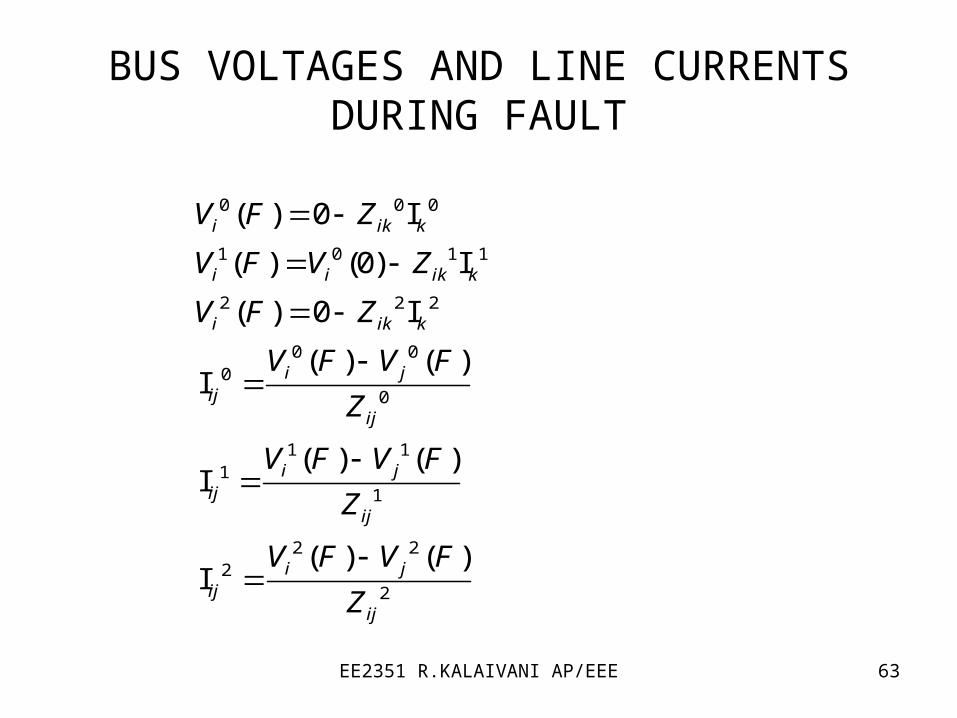
BUS VOLTAGES AND LINE CURRENTS DURING FAULT
0 0 0
1 0 1 1
2 2 2
0 00
0
1 11
1
2 22
2
( ) 0 I
( ) (0) I
( ) 0 I
( ) ( )I
( ) ( )I
( ) ( )I
i ik k
i i ik k
i ik k
i jij
ij
i jij
ij
i jij
ij
V F Z
V F V Z
V F Z
V F V F
Z
V F V F
Z
V F V F
Z

EE2351 R.KALAIVANI AP/EEE 64
UNIT V
STABILITY ANALYSIS

EE2351 R.KALAIVANI AP/EEE 65
STABILITY The tendency of a power system to develop restoring
forces equal to or greater than the disturbing forces to maintain the state of equilibrium.
Ability to keep the machines in synchronism with another machine

EE2351 R.KALAIVANI AP/EEE 66
CLASSIFICATION OF STABILITY
Steady state stability Ability of the power system to regain synchronism after small and
slow disturbances (like gradual power changes)
Dynamic stability Ability of the power system to regain synchronism after small
disturbances occurring for a long time (like changes in turbine speed, change in load)
Transient stability This concern with sudden and large changes in the network
conditions i.e. . sudden changes in application or removal of loads, line switching operating operations, line faults, or loss of excitation.

EE2351 R.KALAIVANI AP/EEE 67
Steady state limit is the maximum power that can be transferred without the system become unstable when the load in increased gradually under steady state conditions.
Transient limit is the maximum power that can be transferred without the system becoming unstable when a sudden or large disturbance occurs.
EE2351 R.KALAIVANI AP/EEE 68
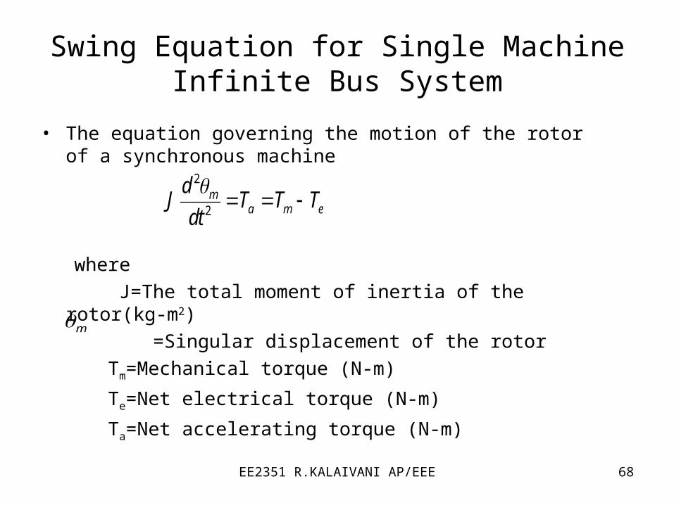
Swing Equation for Single Machine Infinite Bus System
• The equation governing the motion of the rotor of a synchronous machine
where
J=The total moment of inertia of the rotor(kg-m2)
=Singular displacement of the rotor
Tm=Mechanical torque (N-m)
Te=Net electrical torque (N-m)
Ta=Net accelerating torque (N-m)
2
2m
a m e
dJ T T T
dt
m

EE2351 R.KALAIVANI AP/EEE 69
• Where pm is the shaft power input to the machine
pe is the electrical power
pa is the accelerating power
2 2
2 2
2
2
m sm m
m msm
m m
mm a m e
t
d d
dt dt
d d
dt dt
dJ p p p
dt

EE2351 R.KALAIVANI AP/EEE 70
2
2
2
2
2
2
2
20
20 0
2max2
20
2
2
2
2
2
sin
m
ma m e
machinesm
m a m e
sm machine machine
a m es
s
a m e
m a
a
J M
dM p p p
dtH
M S
d p p pH
dt S S
H dp p p
dt
f
H dp p p
f dt
f fdp p p
dt H Hd
dt
fd dp
dt H dt
δ and ωs are in electrical radian
p.u
p.u
H=machine inertia constant
EE2351 R.KALAIVANI AP/EEE 71
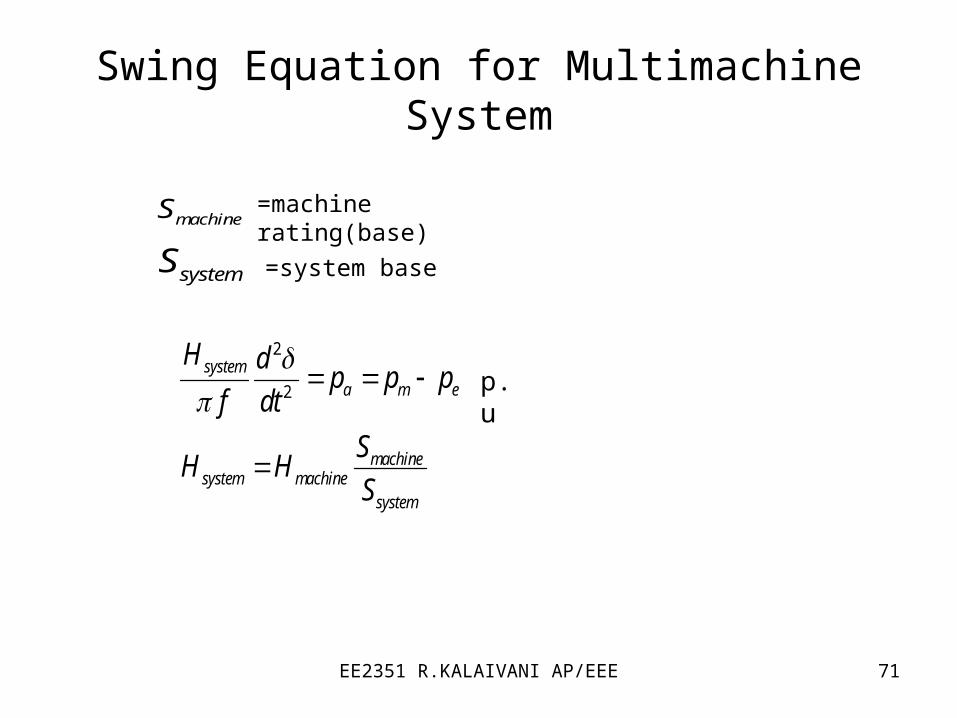
Swing Equation for Multimachine System
2
2
systema m e
machinesystem machine
system
H dp p p
f dt
SH H
S
p.u
machineS =machine rating(base)
systemS =system base
EE2351 R.KALAIVANI AP/EEE 72
Rotor Angle Stability
• It is the ability of interconnected synchronous machines of a power system to maintain in synchronism. The stability problem involves the study of the electro mechanical oscillations inherent in power system.
• Types of Rotor Angle Stability
1. Small Signal Stability (or) Steady State Stability
2. Transient stability
EE2351 R.KALAIVANI AP/EEE 73
Voltage Stability
It is the ability of a power system to maintain steady acceptable voltages at all buses in the system under normal operating conditions and after being subjected to a disturbance.
The major factor for instability is the inability of the power system to meet the demand for reactive power.
EE2351 R.KALAIVANI AP/EEE 74
• Mid Term Stability
It represents transition between short term and long
term responses.
Typical ranges of time periods.
1. Short term : 0 to 10s
2. Mid Term : 10 to few minutes
3. Long Term : a few minutes to 10’s of minutes• Long Term Stability
Usually these problem be associated with
1. Inadequacies in equipment responses.
2. Poor co-ordination of control and protection equipment.
3. Insufficient active/reactive power reserves.

EE2351 R.KALAIVANI AP/EEE 75
Equal Area Criterion
• This is a simple graphical method to predict the transient stability of two machine system or a single machine against infinite bus. This criterion does not require swing equation or solution of swing equation to determine the stability condition.
• The stability conditions are determined by equating the areas of segments on power angle diagram.
EE2351 R.KALAIVANI AP/EEE 76
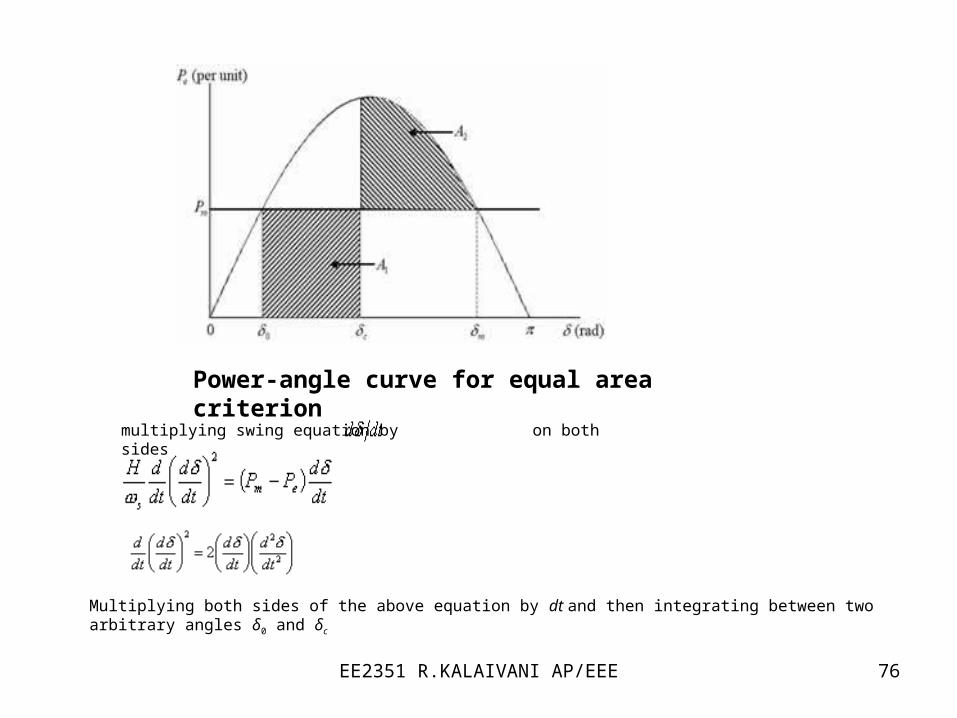
Power-angle curve for equal area criterion
multiplying swing equation by on both sides
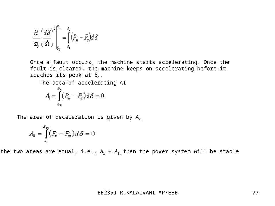
Multiplying both sides of the above equation by dt and then integrating between two arbitrary angles δ0 and δc
EE2351 R.KALAIVANI AP/EEE 77
Once a fault occurs, the machine starts accelerating. Once the fault is cleared, the machine keeps on accelerating before it reaches its peak at δc ,
The area of accelerating A1
The area of deceleration is given by A2
If the two areas are equal, i.e., A1 = A2, then the power system will be stable
EE2351 R.KALAIVANI AP/EEE 78
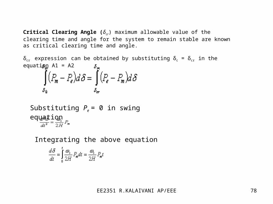
Critical Clearing Angle (δcr) maximum allowable value of the clearing time and angle for the system to remain stable are known as critical clearing time and angle.
δcr expression can be obtained by substituting δc = δcr in the equation A1 = A2
Substituting Pe = 0 in swing equation
Integrating the above equation

EE2351 R.KALAIVANI AP/EEE 79
Replacing δ by δcr and t by tcr in the above equation, we get
the critical clearing time as
EE2351 R.KALAIVANI AP/EEE 80
Factors Affecting Transient Stability
• Strength of the transmission network within the system and of the tie lines to adjacent systems.
• The characteristics of generating units including inertia of rotating parts and electrical properties such as transient reactance and magnetic saturation characteristics of the stator and rotor.
• Speed with which the faulted lines or equipments can be disconnected.
EE2351 R.KALAIVANI AP/EEE 81
Numerical Integration methods
Modified Euler’s method
Runge-Kutta method
EE2351 R.KALAIVANI AP/EEE 82
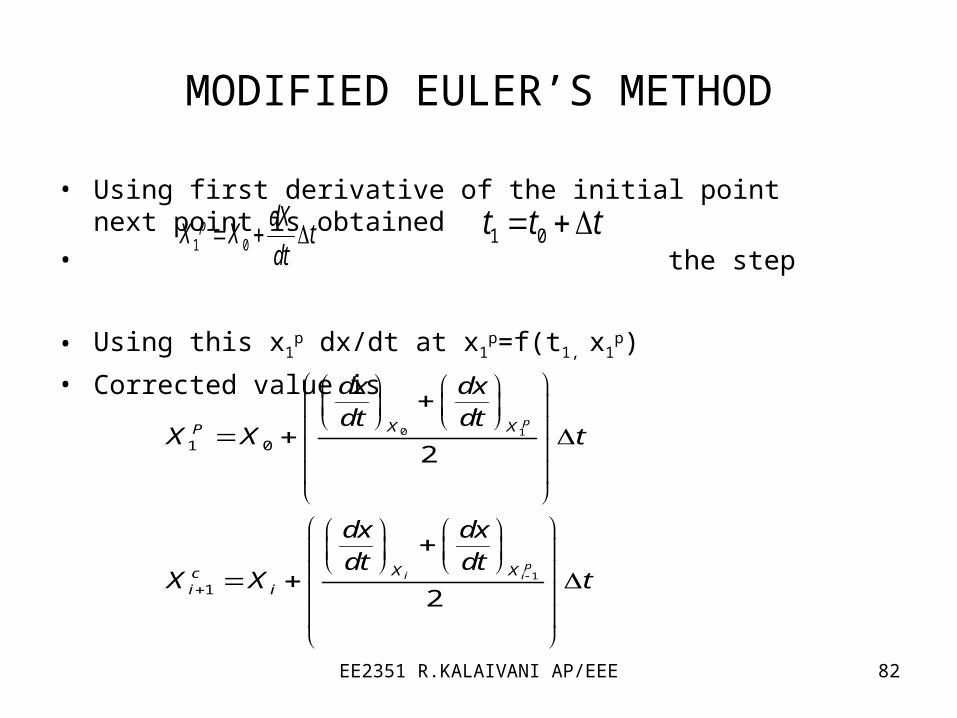
MODIFIED EULER’S METHOD
• Using first derivative of the initial point next point is obtained• the step
• Using this x1p dx/dt at x1
p=f(t1, x1
p)
• Corrected value is
1 0p dX
X X tdt
0 1
1
1 0
1
2
2
p
pi i
X XP
X Xci i
dx dxdt dt
X X t
dx dxdt dt
X X t
1 0t t t

EE2351 R.KALAIVANI AP/EEE 83
Numerical Solution of the swing equation
• Input power pm=constant
• At steady state pe=pm,
• At synchronous speed
10
1max
'
1max1
sin mp
p
E Vp
X
0
'
2max2
0
E Vp
X
EE2351 R.KALAIVANI AP/EEE 84
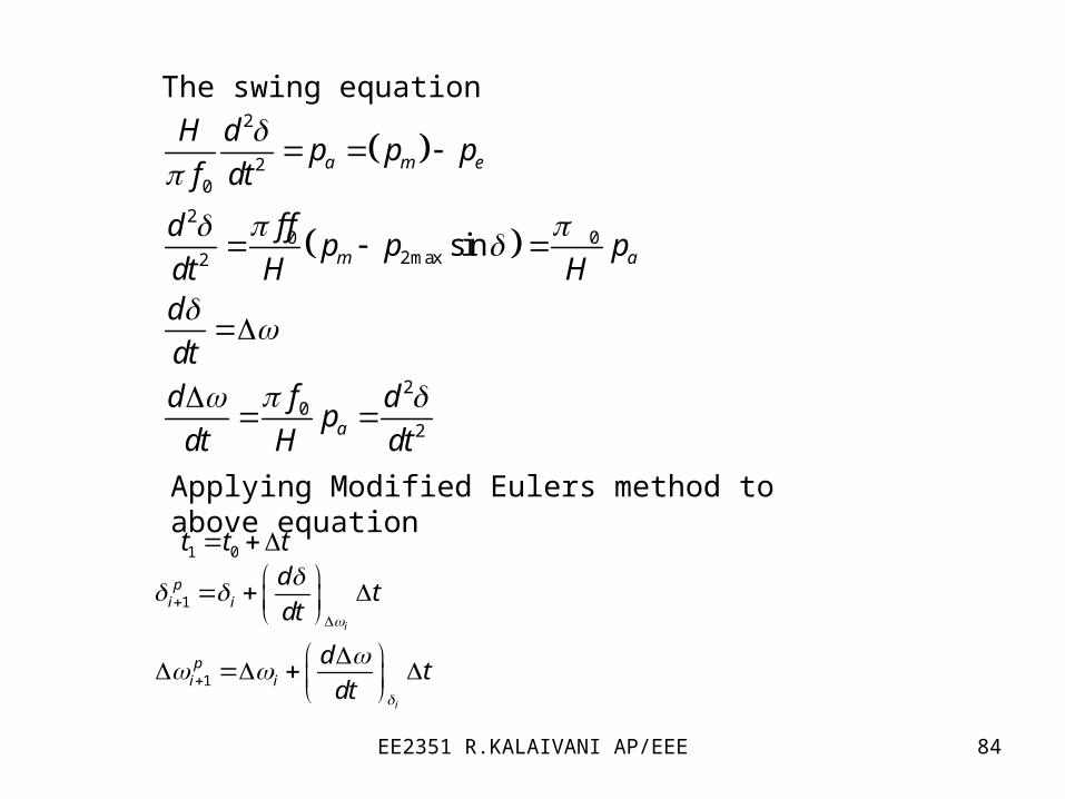
2
20
20 0
2max2
20
2
sin
a m e
m a
a
H dp p p
f dt
f fdp p p
dt H Hd
dt
fd dp
dt H dt
The swing equation
Applying Modified Eulers method to above equation
1 0t t t
1
1
i
i
pi i
pi i
dt
dt
dt
dt

EE2351 R.KALAIVANI AP/EEE 85
• The derivatives at the end of interval
1
11
1
0
pi
ppii
pi
a
d
dt
fdp
dt H
The corrected value
1
1
1
1
2
2
pi i
pi i
ci i
ci i
d ddt dt
t
d ddt dt
t

EE2351 R.KALAIVANI AP/EEE 86
Runge-Kutta Method• Obtain a load flow solution for pretransient conditions• Calculate the generator internal voltages behind transient reactance.• Assume the occurrence of a fault and calculate the reduced admittance matrix• Initialize time count K=0,J=0• Determine the eight constants
1 1
1 2
1 12 1
1 12 2
2 23 1
2 23 2
3 34 1
3 34 2
1 2 3 4
( , )
( , )
( , )2 2
( , )2 2
( , )2 2
( , )2 2
( , )2 2
( , )2 2
2 2
k k k
k k k
k kk k k
k kk k k
k kk k k
k kk k k
k kk k k
k kk k k
k k k
k
K f t
l f t
K lK f t
K ll f t
K lK f t
K ll f t
K lK f t
K ll f t
K K K K
1 2 3 4
6
2 2
6
k
k k k k
kl l l l
EE2351 R.KALAIVANI AP/EEE 87
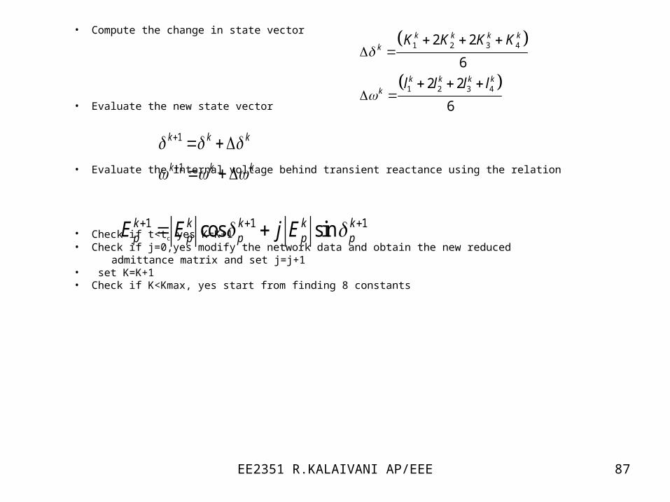
• Compute the change in state vector
• Evaluate the new state vector
• Evaluate the internal voltage behind transient reactance using the relation
• Check if t<tc yes K=K+1• Check if j=0,yes modify the network data and obtain the new reduced admittance matrix and set j=j+1• set K=K+1• Check if K<Kmax, yes start from finding 8 constants
1
1
k k k
k k k
1 2 3 4
1 2 3 4
2 2
6
2 2
6
k k k k
k
k k k k
k
K K K K
l l l l
1 1 1cos sink k k k kp p p p pE E j E