Embed Size (px)
Citation preview

EE16.468/16.568 Lecture 5Electro-optics
Electro-optic effect:
...),( 3)3(2)2()1(0 EEEP
, D
,0 B
,t
BE
,t
DjH
EPED 0
Linear electro-optic effect:
)1( )2()1(0 kijkijij E ,1 kijk Er
Pockels effect
Kerr effect
2
2
2
0
33
22
11
0
00
0
00
z
y
x
n
n
n
When no E applied,
Refractive indices on principle axes

EE16.468/16.568 Lecture 5Electro-optics
,22
12
2
2
2
2
2
20
2
33
2
22
2
11
2
zyx
zyxe n
z
n
y
n
x
r
DDDDU
,12
2
2
2
2
2
zyx n
z
n
y
n
x Refractive index ellipsoid
Refractive index ellipsoid:
DD
DEU e
2
1
2
1 When no electric field applied,
nx
ny
nz

EE16.468/16.568 Lecture 5Electro-optics
,0 kijkij ErWhen electric field applied,
Refractive index ellipsoid:
:ijkr 3x3x3 tensor, 27 components
,jikijk rr
DD
DEU e
2
1
2
1 Generally,
,1,
jijiij xx is a 3x3 tensor, = -1 or = -1
Why?
x
y
zx
y
z
y
x
z
No EO effect for crystal with central symmetry, why?
x
y
z+
-,zjizzijz ErEr

EE16.468/16.568 Lecture 5Electro-optics
,01 kijk Er
,jikijk rr
j i = 1 2 3
1
2
3
1 6 5
6 2 4
5 4 3
3
2
1
636261
535251
434241
333231
232221
131211
0
E
E
E
rrr
rrr
rrr
rrr
rrr
rrr

EE16.468/16.568 Lecture 5Electro-optics
When Ez only,
3
636261
535251
434241
333231
232221
131211
0 0
0
E
rrr
rrr
rrr
rrr
rrr
rrr

EE16.468/16.568 Lecture 5Electro-optics
Take LiNbO3 as an example :
,1111 2
3320
2132
0
2132
0
zEr
nyEr
nxEr
n zzz
,11
3320
2
z
e
Ernn
,2
133
300 ze Ernnn
,2
113
300 zErnn
3330
3
22
51
51
33
1322
1322
0 0
0
00
00
00
00
0
0
Er
E
r
r
r
r
rr
rr
,1
'
1132
020
zEr
nn
,2
133
30 ze Ernn

EE16.468/16.568 Lecture 5Electro-optics
Take LiNbO3 as an example:
,2
133
30 zErnn
Z cut
TM polarization
TE polarization
,2
113
300 zErnn

EE16.468/16.568 Lecture 5Electro-optics
,2
133
300 ze Ernnn ,
2
133
30 zErnn
,2
113
300 zoo Ernnn ,
2
113
30 zErnn
Different index changes of TE and TM waves

EE16.468/16.568 Lecture 5Electro-optics
Take LiNbO3 Intensity modulator Z cutTM polarization
,21 AAAout ,2
10
01LnieAA ,
2
1 )(02
0 LnnieAA
),1(2
10
0nLiLni
out eeAA ),2/(cos)1(4
1 20
2
0
2nLIeIAI nLi
outout
),)2
1((cos)(cos 33
30
20
20 L
d
VnInLIIout
,2/)2
1( 33
30
L
d
Vn
Ln
dV
3330

EE16.468/16.568 Lecture 5Electro-optics
Take LiNbO3 Intensity modulator Z cutTM polarization
),)2
1((cos)(cos 33
30
20
20 L
d
VnInLIIout
Frequency double region
Linear region

EE16.468/16.568 Lecture 5Electro-optics
Operating characteristics
,max
minmax
I
II
• Insertion loss (dB):
• Modulation depth
• Bandwidth: the highest frequency the modulator can operate, R and C
%,100 0min I
),log(10)(in
out
I
IdBIL

EE16.468/16.568 Lecture 5Electro-optics
for a channel waveguide, assuming the E filed is uniform,
• Power consumption: P/f, f: bandwidth
,)(2
1 2 dVEffWPe
),(2
)(2
1 22 ELdW
dVEW d Take LiNbO3 as an example:
LndVE
3330
/
,)(2
)(2
1 2
3330
2
nL
dWdVEW d P/f ~ 2µW/MHz
d
LW
d
AC d
C ~ 0.4pF

EE16.468/16.568 Lecture 5Electro-optics
for a bulk EO modulators, assuming the E filed is uniform,
• Power consumption: P/f, f: bandwidth
,)(2
1 2 dVEffWPe
),(2
)(2
1 22 ELdW
dVEW d
Take LiNbO3 as an example:Ln
dVE33
30
/
,)(2
)(2
1 2
3330
2
nL
dWdVEW d P/f ~ 2W/MHz
z ,2
133
30 zErnn
d
LW
d
AC d
C ~ 3pF

EE16.468/16.568 Lecture 5Electro-optics
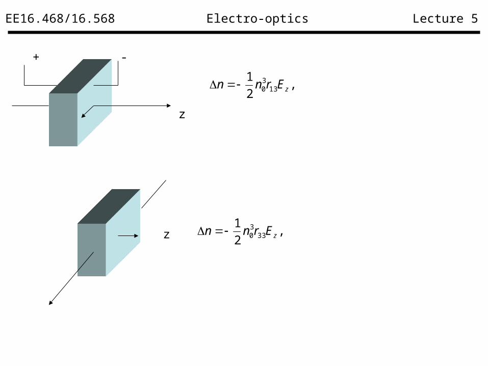
Phase modulator:
,2
2
1
033
30 LErn z
,2
133
30 zErnn Phase shift due to the applied voltage:
,33
30
0
rnE
L
dV z
Examples:
EE16.468/16.568 Lecture 5Electro-optics
+ -
z
,2
113
30 zErnn
z ,2
133
30 zErnn

EE16.468/16.568 Lecture 5Electro-optics
Polarization modulator:
,2
122
30 yx Ernn
Phase shift due to the applied voltage:
,2 33
30
0
rnE
L
dV
0
0
00
00
00
00
0
0
2
22
51
51
33
1322
1322
0 E
r
r
r
r
rr
rr
x
y
,2
122
30 yy Ernn

EE16.468/16.568 Lecture 5Electro-optics
Polarization modulator:
,2
122
30 yx Ernn
Phase difference due to the applied voltage:
,/223022
30 WVrLnErLn yy
x
y
,2
122
30 yy Ernn Ay
Ax
,sin0, AA in
,cos0, AA iny
),2
1(exp(sin)exp(sin 22
30000, yxout ErnnLiALniAA
),2
1(exp(cos)exp(cos 22
30000, yyouty ErnnLiALniAA
W

EE16.468/16.568 Lecture 5Electro-optics
Polarization modulator: Phase difference due to the applied voltage:
,/223022
30 WVrLnErLn yy
x
y
Ay
Ax
W
When = /2,
Ay
Ax
Ay
Ax
When = ,
Ay
Ax

EE16.468/16.568 Lecture 5Electro-optics
,/2
1 30 dVnn
0
30
60
90
120
150
180
210
240
0 1 2 3 4
L = 2mm
L = 5mm
Bias (V)
Pha
se S
hift
(de
gree
)
TE-TM converter:

EE16.468/16.568 Lecture 5Electro-optics
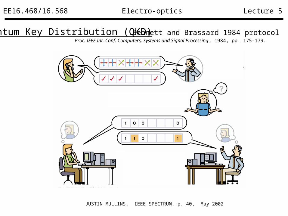
Quantum Key Distribution (QKD)
JUSTIN MULLINS, IEEE SPECTRUM, p. 40, May 2002
Single photon
Bennett and Brassard 1984 protocol Proc. IEEE Int. Conf. Computers, Systems and Signal Processing, 1984, pp. 175–179.
EE16.468/16.568 Lecture 5Electro-optics
Quantum Key Distribution (QKD)
JUSTIN MULLINS, IEEE SPECTRUM, p. 40, May 2002
Bennett and Brassard 1984 protocol Proc. IEEE Int. Conf. Computers, Systems and Signal Processing, 1984, pp. 175–179.

EE16.468/16.568 Lecture 5Electro-optics
Quantum Key Distribution (QKD)
W. T. Buttler, etal. Physical Review A, Vol 57, 1998, pp. 2379-2382

EE16.468/16.568 Lecture 5Electro-optics
Integrated QKD Receiver
Input photon polarization
states
Detection polarization
basis
Final polarization states
Si single photon detector
signal
TE Linear TE 0
TE Circular TE & TM x
TM Linear TM 1
TM Circular TE & TM x
Circular – left-hand
Linear TE & TM x
Circular – left-hand
Circular TE 0
Circular – right-hand
Linear TE & TM x
Circular – right-hand
Circular TM 1
Transmitter: Alice
Receiver: Bob
QKD Links
QKD Links
Receiver: Bob

EE16.468/16.568 Lecture 5Electro-optics
,/2
1 3 dVnn
0
30
60
90
120
150
180
210
240
0 1 2 3 4
L = 2mm
L = 5mm
Bias (V)
Pha
se S
hift
(de
gree
)

EE16.468/16.568 Lecture 5Electro-optics
Input photon polarization states
Applied voltage
Detection polarization basis
Final polarization states
detected signal
TE 0 Linear TE 0
TE V Circular Circular x
TM 0 Linear TM 1
TM V Circular Circular x
Circular – left-hand 0 Linear Circular x
Circular – left-hand V Circular TE 0
Circular – right-hand 0 Linear Circular x
Circular – right-hand V Circular TM 1

EE16.468/16.568 Lecture 5Electro-optics
Poling of polymer materials, contact poling and corona poling:
EO Polymer poling

EE16.468/16.568 Lecture 5Electro-optics
• Lower voltage ~ 800V
• Good film quality
• Easy control of poling voltage
Advantages:
• Uniform poling voltage
Heating/Cooling block
V
Buffer Layer
Film
Poling Electrode
• Select poling area
Heating/Cooling blockBuffer Layer
EO polymer
ElectrodeNeedle
V

EE16.468/16.568 Lecture 5Electro-optics
I-V curve during poling:
• Poling voltage : 900V
• EO coefficient ~ 22pm/V

EE16.468/16.568 Lecture 5Electro-optics
TM-pass waveguide Polarizer
TM input TE input
Before poling After poling
n (TE) 1.594 1.591
n (TM) 1.594 1.598

EE16.468/16.568 Lecture 5Electro-optics
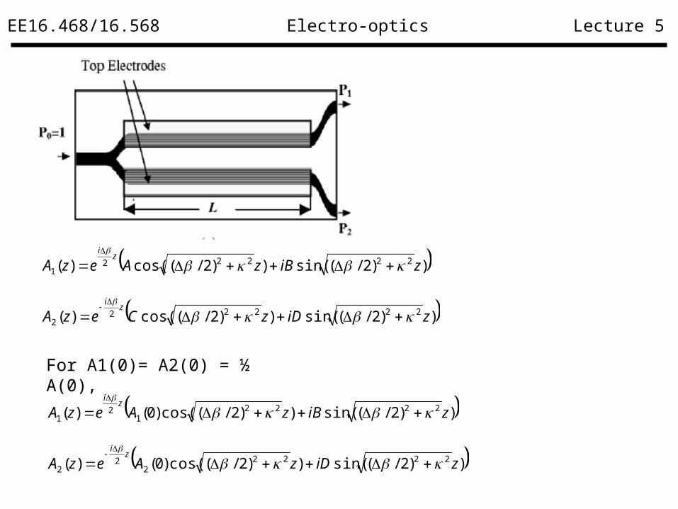
Directional coupler:
1 3
Un-connected port
A1(z)
A2(z)
For A1(0) = A1, A2(0) =0
4
ziezAidz
zdA )()(
21
ziezAidz
zdA )()(
12
12
zizi ezAzAdz
di
dz
zdAe
dz
d
)()(
)(1
22
1
0)()()(
121
21
2
zAdz
zdAi
dz
zAd
0)()()(
222
22
2
zAdz
zdAi
dz
zAd

EE16.468/16.568 Lecture 5Electro-optics
Directional coupler:
1 3
Un-connected port
A1(z)
A2(z)
For A1(0) = A1, A2(0) =0
4
0)()()(
121
21
2
zAdz
zdAi
dz
zAd
0)()()(
222
22
2
zAdz
zdAi
dz
zAd
))2/(sin())2/(cos()( 222221 ziBzAezA
zi
))2/(sin())2/(cos()( 222222 ziDzCezA
zi

EE16.468/16.568 Lecture 5Electro-optics
1 3
Un-connected port
A1(z)
A2(z)
For A1(0) = A1, A2(0) =0
4
))2/(sin())2/(cos()( 222221 ziBzAezA
zi
))2/(sin())2/(cos()( 222222 ziDzCezA
zi
))2/(sin())2/(cos()0()( 222221
21 ziBezAezA
zi
zi
))2/(sin()( 2222 ziDezA
zi
)(
))2/(sin(2
))2/(cos()2/()(
1
222222222
zAi
zeDziDezAd
d zi
zi
22
1
4)(
)0(
AD
22
1
4)(
)0(2
A
B

EE16.468/16.568 Lecture 5Electro-optics
Directional coupler:
1 3
Un-connected port
A1(z)
A2(z)
)cos()0()( 11 zAzA
)sin()0()( 12 ziAzA
For A1(0) = A1, A2(0) =0
4
LPP
2
222
2
2
02 2sin
2
/
),2
1(
2233
30 zErnn
))2/(sin()2/(
)0()( 22
22
122 z
AiezA
zi
EE16.468/16.568 Lecture 5Electro-optics
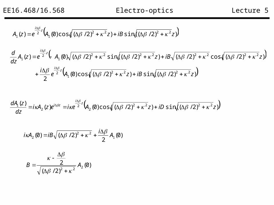
For A1(0)= A2(0) = ½ A(0),
))2/(sin())2/(cos()( 222221 ziBzAezA
zi
))2/(sin())2/(cos()( 222222 ziDzCezA
zi
))2/(sin())2/(cos()0()( 22221
21 ziBzAezA
zi
))2/(sin())2/(cos()0()( 22222
22 ziDzAezA
zi
EE16.468/16.568 Lecture 5Electro-optics
))2/(sin())2/(cos()0()( 22221
21 ziBzAezA
zi
))2/(sin())2/(cos()0(
2
))2/(cos()2/())2/(sin()2/()0()(
22221
2
222222221
21
ziBzAei
ziBzAezAdz
d
zi
zi
))2/(sin())2/(cos()0()()( 2222
22
21 ziDzAeiezAidz
zdA zi
zi
)0(2
)2/()0( 122
2 Ai
iBAi
)0()2/(2
222AB

EE16.468/16.568 Lecture 5Electro-optics
))2/(sin())2/(cos()0(
2
))2/(cos()2/())2/(sin()2/()0()(
22221
2
222222221
21
ziBzAei
ziBzAezAdz
d
zi
zi
))2/(sin())2/(cos()0()()( 2222
22
21 ziDzAeiezAidz
zdA zi
zi
)0()2/(2
122AD
))2/(sin())2/(cos()0()( 22221
21 ziBzAezA
zi
))2/(sin())2/(cos()0()( 22222
22 ziDzAezA
zi
)0()2/(2
122AB

EE16.468/16.568 Lecture 5Electro-optics
)0()2/(2
122AD
))2/(sin())2/(cos()0()( 22221
21 ziBzAezA
zi
))2/(sin())2/(cos()0()( 22222
22 ziDzAezA
zi
)0()2/(2
122AB

EE16.468/16.568 Lecture 5Electro-optics
)0()2/(2
122AD
))2/(sin())2/(cos()0()( 22221
21 ziBzAezA
zi
))2/(sin())2/(cos()0()( 22222
22 ziDzAezA
zi
)0()2/(2
122AB
When = 0,
)sin()cos()0()( 11 zizAzA
)sin()cos()0()( 12 zizAzA

EE16.468/16.568 Lecture 5Electro-optics
When 0,
))2/((sin)2/(2))2/((cos)0()( 222
2
22
22211 zzPzP
))2/((sin)2/(2))2/((cos)0()( 222
2
22
22222 zzPzP

EE16.468/16.568 Lecture 5Electro-optics
Traveling-wave electrodes: 1 3
Un-connected port
A1(z)
A2(z)
)cos()0()( 11 zAzA
)sin()0()( 12 ziAzA
For A1(0) = A1, A2(0) =0
4
For high-speed electrode using transmission lines:
Vg(t) VL
A
z = 0
B
l
ZL
z = - l
Z0Vi
-V0
+V0=
ZL Z0-
ZL Z0+

EE16.468/16.568 Lecture 5Electro-optics
Standing waves for impedance mismatching:
Vg(t) VL
A
z = 0
B
l
ZL
z = - l
Z0Vi
-V0
+V0=
ZL Z0-
ZL Z0+
|V(z)|
2|V0| +
- -3/4 -/2 -/4
Standing waves
,2
133
30 zErnn
Cancelled

EE16.468/16.568 Lecture 5Electro-optics
Traveling waves for impedance matching:
Vg(t) VL
A
z = 0
B
l
ZL
z = - l
Z0Vi
-V0
+V0=
ZL Z0-
ZL Z0+
traveling waves
,2
133
30 zErnn
|V(z)|
|V0| +
- -3/4 -/2 -/4

EE16.468/16.568 Lecture 5Electro-optics
Kerr effect :

EE16.468/16.568 Lecture 5Electro-optics
Applications of Kerr effect :
• Self-phase modulation
,22 InIKEn
• Self-Focusing

EE16.468/16.568 Lecture 5Electro-optics
Acoustic-optic Modulators• Bragg condition:
,2
sin2
2
),2
cos()( 00 xtnnxn
,2
1
sIn
,2sInR

EE16.468/16.568 Lecture 5Electro-optics
Doppler shift
Angle mismatch

EE16.468/16.568 Lecture 5Electro-optics
Acoustic –optics devices
• Modulator
• Beam Scanner
Number of resolvable spots:
Bandwidth: ,22
sin fvs
,D
Bvs

EE16.468/16.568 Lecture 5Electro-optics
Acoustic –optics devices • Free space inter-connector
• Isolator

EE16.468/16.568 Lecture 5Electro-optics
Light propagation in anisotropic crystals
Optical axises
no
o light

EE16.468/16.568 Lecture 5Electro-optics
Light propagation in anisotropic crystals
Optical axis
no
o light
ne

EE16.468/16.568 Lecture 5Electro-optics
Light propagation in anisotropic crystals
Optical axis
no
ne
Polarization beam splitter

EE16.468/16.568 Lecture 5Electro-optics
Light propagation in anisotropic crystals

EE16.468/16.568 Lecture 5Electro-optics
Light propagation in anisotropic crystals
ne no

EE16.468/16.568 Lecture 5Electro-optics
Faraday rotator

EE16.468/16.568 Lecture 5Electro-optics
Fiber–optics devices • Coupler FC/APC
SC/PC
FC/PC
SC/APC

EE16.468/16.568 Lecture 5Electro-optics
Circulator


