Embed Size (px)
Citation preview
10/01/14
1
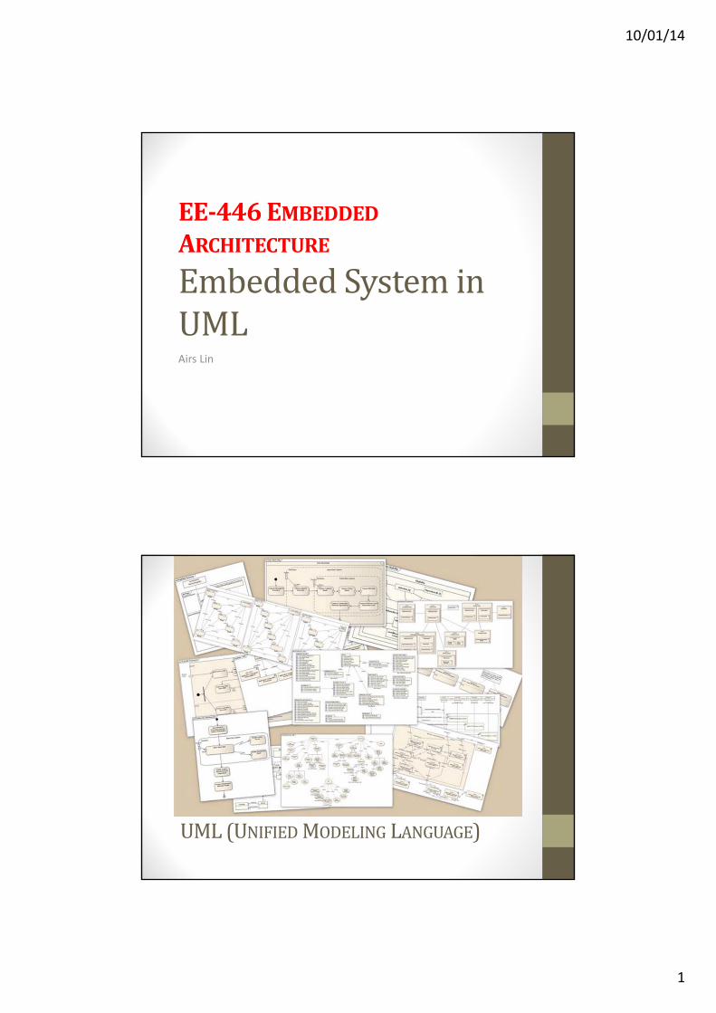
EE‐446EMBEDDEDARCHITECTURE
EmbeddedSysteminUMLAirs Lin
UML(UNIFIEDMODELING LANGUAGE)

10/01/14
2
WhatisUML?
• Created and developed by Grady Booch, Ivar Jacobson, and James Rumbaughat Rational Software (1994~1996)• In 1997, it was adopted as a standard and managed by OMG (Object Management
Group)• In 2000, the UML was accepted by the ISO (International Organization for
Standardization) as an approved ISO standard
• The UML is a graphical “Object‐Oriented Modeling Language”• General‐purpose modeling language in the field of software engineering• Provides a standard way to visualize the design of a system• Widely used for business modeling and other non‐software systems
• UML is not a "process"• It does not tell you how to do things, only what you should do
WhyUseUML?• UML is a fusion of ideas from several precursor modeling languages
• We need a modeling language to:
• Help develop efficient, effective and correct designs, particularly Object‐Oriented Designs
• Communicate clearly with project stakeholders (concerned parties: developers, customers, etc.)
• Give us the “big picture” view of the project

10/01/14
3
TypesofUML2.xDiagrams
Most Helpful UMLDiagrams• Use Case diagram: represents functions of a system from the user's point of view
• Class diagram: represents the static structure in terms of classes and relationships
• Sequence diagram: is a temporal representation of objects and their interactions
• Statechart diagram: represents the behavior of a class in terms of states
• Activity diagram: represents the behavior of an operation as a set of actions
• Deployment diagram: represents the deployment of components on particular pieces of hardware
10/01/14
4
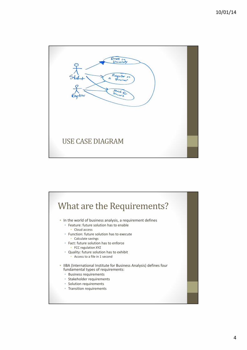
USECASEDIAGRAM
Whatarethe Requirements?• In the world of business analysis, a requirement defines
• Feature: future solution has to enable• Cloud access
• Function: future solution has to execute• Calculate savings
• Fact: future solution has to enforce• FCC regulation XYZ
• Quality: future solution has to exhibit• Access to a file in 1 second
• IIBA (International Institute for Business Analysis) defines four fundamental types of requirements:• Business requirements• Stakeholder requirements• Solution requirements• Transition requirements

10/01/14
5
RequirementAnalysis• Functional requirements
• Describe a list of functions that the system must accomplish
• Quality (Nonfunctional) requirements
• Describe other constrains
• Performance expectations
• Technologies to be used
UseCaseDiagram• Use Case diagrams model the behavior of a system and help to capture the requirements of the system
• Use Case diagrams describe the high‐level functions and scope of a system
• Use Case diagrams also identify the interactions between the system and its actors
• Use Case and actors describe what the system does and how the actors use it, but not how the system operates internally

10/01/14
6
WhenUseCaseisApplicable?• Before starting a project
• Create Use Case diagrams to model a business so that all participants in the project share an understanding of workers, customers, and activities of the business
• While gathering requirements
• Create Use Case diagrams to capture the system requirements and to present to others what the system should do
• During the analysis and design phases
• Apply the Use Case and actors to identify the classes that the system requires
• During the testing phase
• Apply Use Case diagrams to identify tests for the system
BasicUseCaseSyntax

10/01/14
7
AUseCaseDiagram…• Use Case diagram
• Presents main components of the system
• Shows how the user interacts with those components
• Three main components
• Actor(s)
• Use Case(s)
• System boundary
UMLUseCaseDiagramExample

10/01/14
8
SymbolsofUseCaseDiagram# Name
1 Actor A class of people or system that interact with a system
2 AssociationIndicates that instances of one model element are connected to instances of another model element
3Directed
AssociationDirected association relationships are associations that are navigable in only one direction
4 GeneralizationA generalization relationship is a relationship in which one model element (the child) is based on another model element (the parent)
5 DependencyOne element, or group of elements, acting as the client depends on another element or group of elements that act as the supplier
6 IncludeAn include relationship is a relationship in which one Use Case (the base Use Case) includes the functionality of another Use Case (the inclusion Use Case).
7 ExtendSpecifies that one Use Case (extension) extends the behavior of another Use Case (base). This type of relationship reveals details about a system or application that are typically hidden in a Use Case
8 SystemA System Boundary is a type of partition that represents the boundary between the item you are representing with the Use Cases (inside the boundary) and the actors (outside the boundary)
<<include>>
<<extend>>
UseCaseDiagram–Association(1)
• An association between an actor and a Use Case indicates that the actor and the Use Case communicate with each other
• An actor could be associated to one or several Use Cases
Actor Customer associated with two Use Cases.

10/01/14
9
UseCaseDiagram–Association(2)
Use CaseManage Account associated with Customer and Bank actors.
• Use Case may have one or several associated actors
UseCaseDiagram–DirectedAssociation• Introduce an actor called “Time” to initiate scheduled events

10/01/14
10
UseCaseDiagram–Generalization(1)• A parent Use Case may be specialized into one or more child Use Cases that represent more specific forms of the parent
• A child inherits all structure, behavior, and relationships of the parent
• Generalization is used when you find two or more Use Cases that have commonalities in behavior, structure, and purpose. When this happens, you can describe the shared parts in a new Use Case, that is then specialized by child use cases.
Web Client actor is abstract superclass for Administrator, Editor and Customer
UseCaseDiagram–Generalization(2)• Generalization between Use Cases is similar to generalization between classes – child Use Case inherits properties and behavior of the parent Use Case and may override the behavior of the parent
Phone Order and Internet Order Use Cases are specializations of the abstract Use Case Place Order

10/01/14
11
USECASEDIAGRAM
Actor
WhatisanActor?• All the actor items that live outside the system and interact with the system constitute the system’s context
• The context defines the environment in which the system lives

10/01/14
12
MainCategoriesofActors1. Principal Actors
• People who use the main system functions
2. Secondary Actors
• People that perform administration or maintenance tasks
3. External Hardware
• The unavoidable hardware devices that are part of the application domain and must be used
4. Other Systems
• The other systems with which the system must interact
HowtoFindtheActors1. Who will use the system?
2. Who will install the system?
3. Who will activate the system?
4. Who will maintain the system?
5. Who will shutdown the system?
6. Any other systems will operate with this system?
7. Who will receive the data from the system?
8. Who will provide the data to the system?
9. What function will be automatically executed by the timer?
10. Any other systems will be connected with this system?
11. Any hardware devices will be connected with the system?
12. Any database will be connected with the system?
13. Anyone inside of the company will operate the system?
14. Anyone outside of the company will operate the system?
10/01/14
13
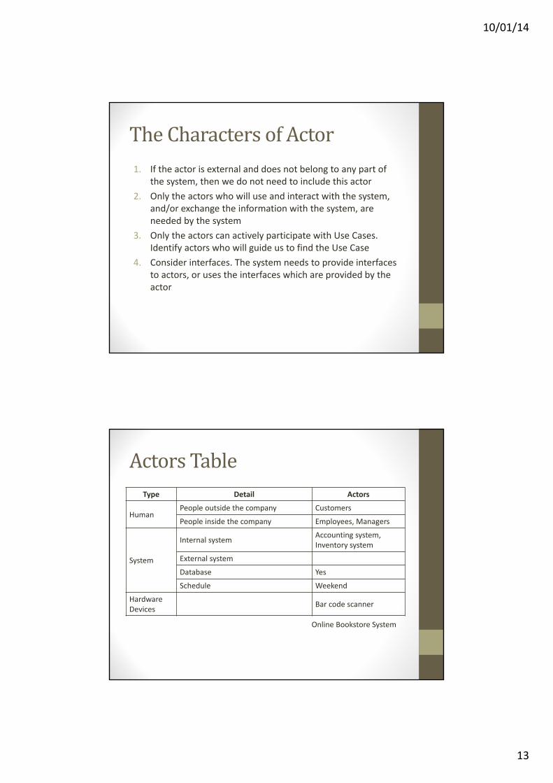
TheCharactersofActor1. If the actor is external and does not belong to any part of
the system, then we do not need to include this actor
2. Only the actors who will use and interact with the system, and/or exchange the information with the system, are needed by the system
3. Only the actors can actively participate with Use Cases. Identify actors who will guide us to find the Use Case
4. Consider interfaces. The system needs to provide interfaces to actors, or uses the interfaces which are provided by the actor
ActorsTableType Detail Actors
HumanPeople outside the company Customers
People inside the company Employees, Managers
System
Internal systemAccounting system, Inventory system
External system
Database Yes
Schedule Weekend
Hardware Devices
Bar code scanner
Online Bookstore System
10/01/14
14
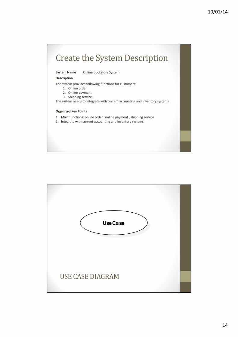
CreatetheSystemDescriptionSystem Name Online Bookstore System
Description
The system provides following functions for customers:1. Online order2. Online payment3. Shipping service
The system needs to integrate with current accounting and inventory systems
Organized Key Points
1. Main functions: online order, online payment , shipping service2. Integrate with current accounting and inventory systems
USECASEDIAGRAM

10/01/14
15
WhyConsiderUseCases?• In a traditional Software Requirements Specification (SRS), features are presented without context. For example:• The system will have to do the following…
• The system should do the following …
• The system will end up doing the following …
• It is of the utmost importance that …
• It would be interesting to …
• A traditional SRS are often expressed in an unstructured way• Very difficult for the system’s stakeholder to absorb
• Use Cases break requirements down into short scenarios• More easily understood
BenefitsofUseCases• Good way to start identifying objects from scenarios
• Test plan can be immediately generated based on Use Cases
• Easier user validation
• Helps technical writers in structuring the overall work on the users manuals at the early stage
• Better traceability throughout the system development process
• Quality of the software is improved by identifying the exception scenarios earlier in the development process
10/01/14
16
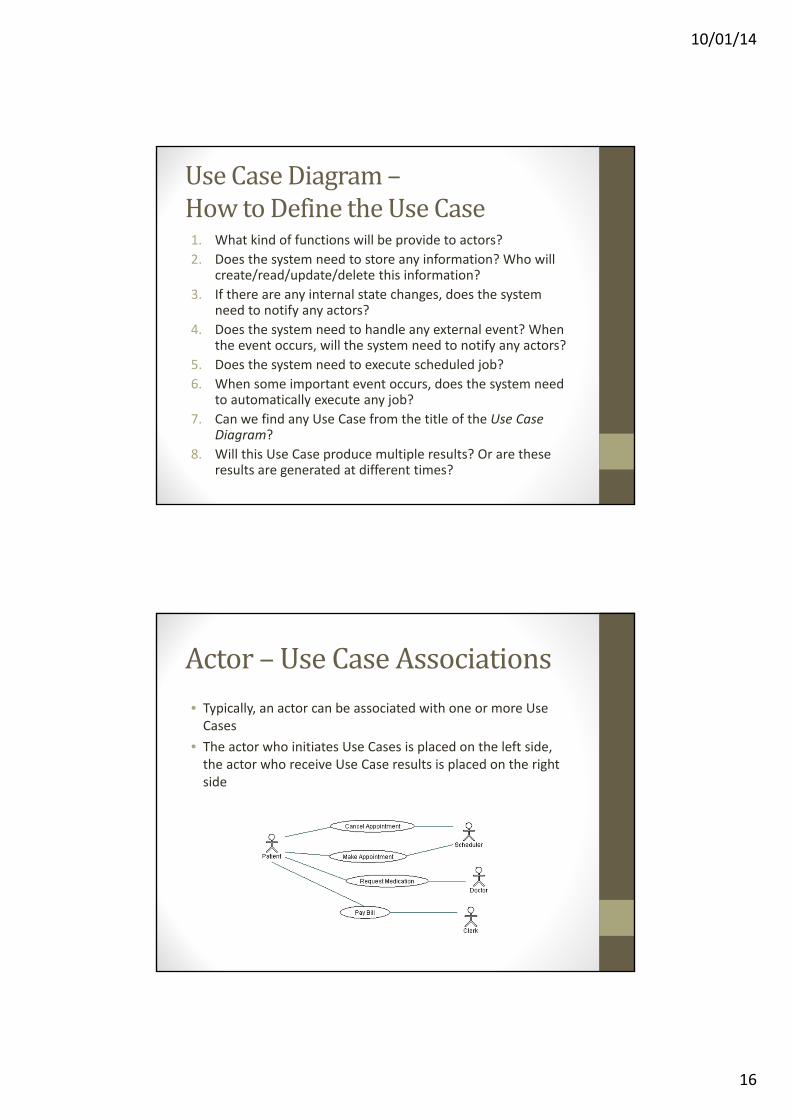
UseCaseDiagram–HowtoDefinetheUseCase1. What kind of functions will be provide to actors?
2. Does the system need to store any information? Who will create/read/update/delete this information?
3. If there are any internal state changes, does the system need to notify any actors?
4. Does the system need to handle any external event? When the event occurs, will the system need to notify any actors?
5. Does the system need to execute scheduled job?
6. When some important event occurs, does the system need to automatically execute any job?
7. Can we find any Use Case from the title of the Use Case Diagram?
8. Will this Use Case produce multiple results? Or are these results are generated at different times?
Actor– UseCaseAssociations• Typically, an actor can be associated with one or more Use Cases
• The actor who initiates Use Cases is placed on the left side, the actor who receive Use Case results is placed on the right side

10/01/14
17
UseCase–NoInternalBehavior• Does not represent any internal behavior that system may have, which is only used by other parts of the system
Incorrect Correct
UseCase–NoInteractionsBetweentheActorsintheSystem
Incorrect
Correct
10/01/14
18
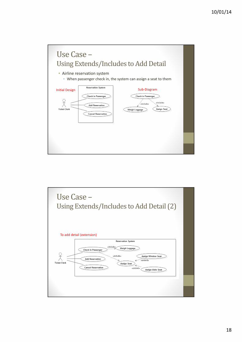
UseCase–UsingExtends/IncludestoAddDetail• Airline reservation system
• When passenger check in, the system can assign a seat to them
Initial Design Sub‐Diagram
UseCase–UsingExtends/IncludestoAddDetail (2)
To add detail (extension)

10/01/14
19
UseCaseDiagram–Library'sInternetPortal• Library members access the library's internet portal
• Log in
• View books
• Order books
UseCaseDiagram–InertialMeasurementUnit(IMU)

10/01/14
20
UseCaseDescriptionUse Case Short description
ActorsWho or what is using this Use Case? Is this used by other Use Cases?
Supporting Actor
Brief DescriptionDetail description
Pre‐conditionsWhat needs to be done before the Use Case is executed?
Post‐conditionsWhat is changed after the Use Case is executed? This can be used to verify if the Use Case has successfully been executed
Basic FlowA list of steps that will normally occur
Alternative FlowsIf something goes wrong or if the normal flow varies, then the alternative flow is described here
Special RequirementsComments and requirements to the Use Case
Use Case RelationshipsSome of the steps might be described in other use cases. These use cases are listed here
UseCaseDescription‐ ExampleUse Case UC2 – View details for a Blu‐ray disc
Actor Customer Supporting Actor
Brief DescriptionAs a customer I would like to view the details for a specific Blu‐ray disc
Pre‐conditionsUC1 must have been done
Post‐conditionsDetails shown
Basic Flow of Events1. Customer clicks on a Blu‐ray from the list2. Web store sends a request about details for the given Blu‐ray disc to the DB3. DB retrieves the requested data and sends it to the Web store4. Web store displays product details
Alternative Flows
Special Requirements
Use Case Relationships
10/01/14
21
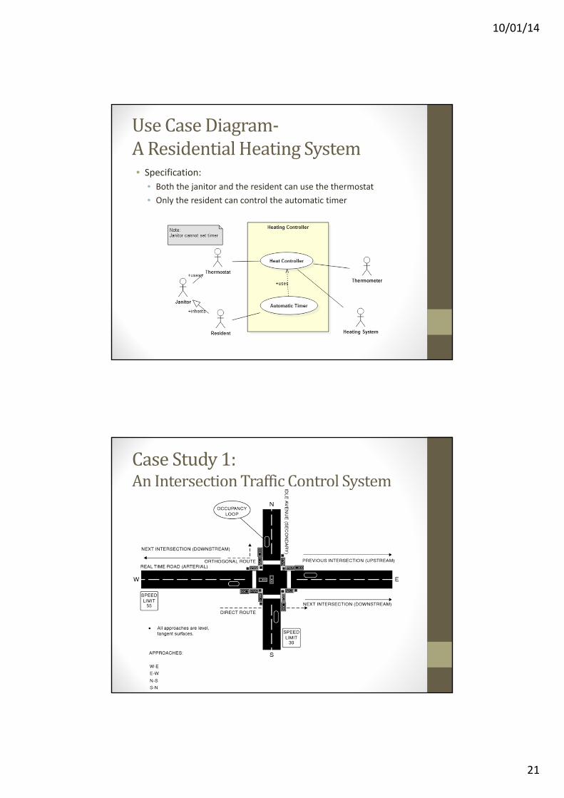
UseCaseDiagram‐AResidentialHeatingSystem• Specification:
• Both the janitor and the resident can use the thermostat
• Only the resident can control the automatic timer
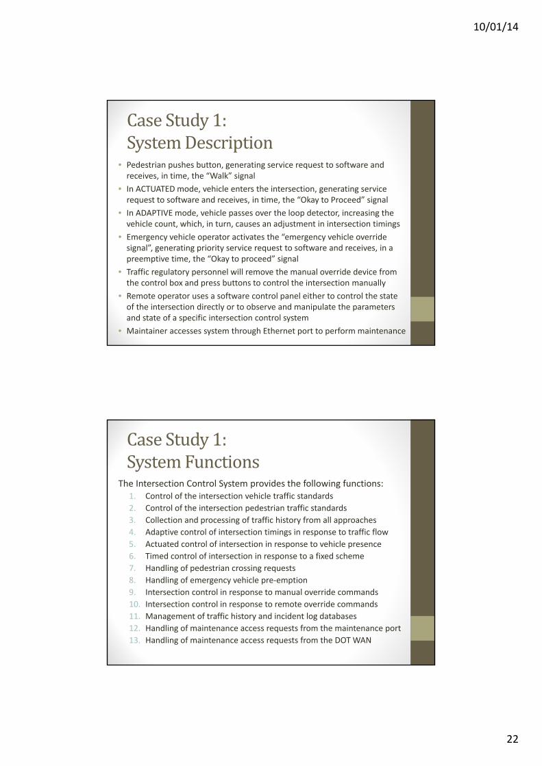
Case Study 1:An IntersectionTraffic Control System
10/01/14
22
Case Study 1:SystemDescription
• Pedestrian pushes button, generating service request to software andreceives, in time, the “Walk” signal
• In ACTUATED mode, vehicle enters the intersection, generating servicerequest to software and receives, in time, the “Okay to Proceed” signal
• In ADAPTIVE mode, vehicle passes over the loop detector, increasing thevehicle count, which, in turn, causes an adjustment in intersection timings
• Emergency vehicle operator activates the “emergency vehicle overridesignal”, generating priority service request to software and receives, in apreemptive time, the “Okay to proceed” signal
• Traffic regulatory personnel will remove the manual override device fromthe control box and press buttons to control the intersection manually
• Remote operator uses a software control panel either to control the stateof the intersection directly or to observe and manipulate the parametersand state of a specific intersection control system
• Maintainer accesses system through Ethernet port to perform maintenance
Case Study 1:SystemFunctions
The Intersection Control System provides the following functions:1. Control of the intersection vehicle traffic standards
2. Control of the intersection pedestrian traffic standards
3. Collection and processing of traffic history from all approaches
4. Adaptive control of intersection timings in response to traffic flow
5. Actuated control of intersection in response to vehicle presence
6. Timed control of intersection in response to a fixed scheme
7. Handling of pedestrian crossing requests
8. Handling of emergency vehicle pre‐emption
9. Intersection control in response to manual override commands
10. Intersection control in response to remote override commands
11. Management of traffic history and incident log databases
12. Handling of maintenance access requests from the maintenance port
13. Handling of maintenance access requests from the DOTWAN

10/01/14
23
Case Study 1:Actors1. Vehicle Presence Detector – User:Motor Vehicle
2. Pedestrian Presence Detector – User: Pedestrian
3. Emergency Vehicle Override – User: Emergency Vehicle
4. Manual Override – User: Traffic Control Officer
5. Remote Override – User: DOT Network
6. Maintenance Interface – User:Maintainer
Case Study 1:Top‐Level Use CaseDiagram

10/01/14
24
CaseStudy2:MedicalClinic• Scenario for the medical clinic
• A patient calls the clinic to make an appointment for a yearly checkup
• The receptionist (scheduler) finds the nearest empty time slot in the appointment book and schedules the appointment for that time slot
CaseStudy2:UseCaseDiagram
• System Requirements• The patient and scheduler are actors involved in making and cancelling appointments
• The patient can request medication from the doctor• The tasks associated with paying the bill happen between the patient and the clerk

10/01/14
25
CaseStudy2:UseCaseDiagram
• System Requirements• The patient and scheduler are actors involved in making and cancelling appointments
• The patient can request medication from the doctor• The tasks associated with paying the bill happen between the patient and the clerk