Embed Size (px)
DESCRIPTION
ee269
Citation preview

Engineer-to-Engineer Note EE-269
a
Technical notes on using Analog Devices DSPs, processors and development toolsContact our technical support at [email protected] and [email protected] visit our on-line resources http://www.analog.com/ee-notes and http://www.analog.com/processors
A Beginner’s Guide to Ethernet 802.3 Contributed by Ralf Neuhaus Rev 1 – June 6, 2005
Copyright 2005, Analog Devices, Inc. All rights reserved. Analog Devices assumes no responsibility for customer product design or the use or application of customers’ products or for any infringements of patents or rights of others which may result from Analog Devices assistance. All trademarks and logos are property of their respective holders. Information furnished by Analog Devices applications and development tools engineers is believed to be accurate and reliable, however no responsibility is assumed by Analog Devices regarding technical accuracy and topicality of the content provided in Analog Devices Engineer-to-Engineer Notes.
Introduction This EE-Note provides an overview of the Ethernet specification and some popular protocols that can be used “on top of” an Ethernet driver. The goal is to provide the reader with the fundamentals of the protocols and the hardware. The figures and explanations will provide excellent guidance for anyone starting off on Ethernet. This EE-Note does not show any software implementations such as a TCP/IP stack, but will simplify their use.
Additionally, this EE-Note serves as the theoretical complement to the Ethernet MAC chapter of the ADSP-BF537 Blackfin® Processor Hardware Reference [16] and to the
EE-Note Ethernet Network Interface for ADSP-BF535 Blackfin Processors (EE-214). [17]
History
The Ethernet Sourcebook, ed. Robyn E. Shotwell (New York: North-Holland, 1985), title page.
When we talk about “Ethernet”, we refer to the implementation methods of layer 1 and layer 2 of the Open Systems Interconnection model (OSI model).
These layers form the physical layer for various Ethernet hardware implementations, while the other OSI layers are implemented in software.
``The diagram ... was drawn by Dr. Robert M. Metcalfe in 1976 to present Ethernet ... to the National Computer Conference in June of that year. On the drawing are the original terms for describing Ethernet. Since then other terms have come into usage among Ethernet enthusiasts.'”
Figure 1. Ethernet History

a
A Beginner’s Guide to Ethernet 802.3 (EE-269) Page 2 of 26
OSI Model The OSI model provides a standard description or "reference model" for how messages should be transmitted between any two points in a telecommunication network.
It consists of seven layers and each layer describes the status of the communications, e.g., Ethernet.
Figure 2 compares the OSI model with the TCP/IP model and its protocols.
Figure 2. Comparison between OSI and TCP/IP Models
TCP/IP Model
The TCP/IP model consists of four layers.
Network Layer The Network layer combines the Data Link layer and Physical layer, including the twisted pair cable, the Physical layer device (PHY), and the Ethernet Media Access Controller (MAC).
Internet Layer The Internet layer consists primarily of a software implementation. The IP header is evaluated or generated by software.
Transport Layer The Transport layer defines what should be done with the data. This layer is based on the following two popular protocols:
UDP is a very simple protocol and is perfect for streaming sequences (e.g., audio or video).
TCP is a highly reliable host-to-host protocol for a controlled connection. TCP is appropriate for applications that require guaranteed delivery.
Application Layer The Application layer includes all available software implementations (e.g., FTP, HTTP, SMTP, DNS, …) that make up the lower layers. These applications can work only in combination with the API of TCP or UDP, which form the software implementation of the Transport layer.
TCP/IP Protocols
The third column of Figure 2 shows possible ways (combinations of sub protocols and
Application Layer
Presentation Layer
Session Layer
Transport Layer
Network Layer
Data Link Layer
Physical Layer
Application
Transport
Internet
Network
User Data Protocol UDP
Internet Protocol IP
FTP SMTP Name Server
NFS
Transmission Control Protocol TCP
Ethernet IEEE 802.3
Token Ring
twisted Pair
optical fiber
coaxial cable
DQDB
OSI model TCP/IP model TCP/IP protocols
HTTP
XDR
RPC
1
2
3
4
5
6
7
Layer

a
A Beginner’s Guide to Ethernet 802.3 (EE-269) Page 3 of 26
physical medium) to build a stack. For instance, FTP, HTTP, or SMTP applications can use TCP, IP, Ethernet IEEE 802.3, and the twisted-pair cable as one way.
RFCs RFCs (request for comments) are very popular in the Ethernet community and form a type of regulation system. RFCs describe many of the Internet protocols as well as standards, procedures, rules, algorithms, and strategies for the communication and network area. An RFC starts as a recommendation; after successful discussion, it is then approved by the Internet community. After publication, this recommendation will be mostly accepted by the market. For instance, decisions of the IAB (Internet Architecture Board) are always published as RCFs.
The most important protocols are: RFC 768 User Data Protocol
RFC 793 Transmission Control Protocol
RFC 791 Internet Protocol
RFC 792 Internet Control Massage Protocol
RFC 826 Address Resolution Protocol RFCs are one of the main ingredients which contribute to the success story of the Ethernet.
Ethernet Family Tree
The Ethernet family tree (Figure 3) gives an overview about the class with the reference to the transport medium. This EE-Note described 10Base-T and 100Base-TX Ethernet only.
10Mbit/s | ---------10Base2
|----------10Base5
|----------10Base-T
|----------FOIRL 10Base-F |--------------10Base-FB
|--------------10Base-FP
|--------------10Base-FL
100Mbit/s |----------100Base-T4 |----------100Base-X |--------------100Base-TX
|--------------100Base-FX
1000Mbit/s |----------1000Base-T |----------1000Base-X
|--------------1000Base-SX
|--------------1000Base-LX
|--------------1000Base-CX
legend :
2 = thin coaxial S = short wavelength
5 = thick coaxial L = long wavelength
T = twisted pair C = short copper cable
F = fiber optics
FOIRL = Fiber Optic Inter-Repeater Link
Figure 3. Ethernet Family Tree
Hardware This section goes deeper in the Physical and Data Link layer of the OSI model. It also describes the RJ45 jack, Magnetic, Power over Ethernet (PoE), and Media Independent Interface (MII) interface. All frequencies are shown in detail to provide the reader with a feeling of the signal chain in the Physical layer and the Data Link layer.
There are many more protocols established as shown in Figure 2.

a
A Beginner’s Guide to Ethernet 802.3 (EE-269) Page 4 of 26
Overview
Figure 4 shows layer 1 and layer 2 in detail and describe all sub-layers of the PHY. For further information, refer to specification IEEE802.3-2002.
Generally, PHYs work in layer 1, and Ethernet MACs are placed in layer 2.
Figure 4. PHY and MAC Layer 100-Mbit Network * MII is optional for 10 Mb/s DTEs and for 100 Mb/s systems and
is not specified for 1 Mb/s systems. ** PMD is specified for 100BASE-X only; 100BASE-T4 does not
use this layer. *** AUTONEG is optional.
The standard connection between the MAC and PHY is the Media Independent Interface (MII). MII Interface is described later in this document after the description of PHY tasks. For 10Mbit/s networks, the PHY works with the Manchester encode and decode mechanism. In 100-Mbit/s networks, the supporting tasks are 4B/5B encode and decode, scrambling, non-return-to-zero/inverted (NRZI) coding, and MLT-3 conversion. Auto-Negotiation is based in the AUTONEG level and works all the time.
Coding Methods
Figure 4 (PHY and MAC layer) shows layer 1 in detail, It includes the PCS, PMA, PMD, and Auto-Negotiation units. All these units are supported by the PHY. The active component
depends on the medium only, such as 10BaseT and 100BaseTX (speed) or 100BaseTX and 100BaseFX (twisted pair - optical), and so on.
This EE-Note describes focuses on the 10BaseT and the 100BaseTX standards. These standards use the following coding mechanisms.
10Mbit/s = Manchester coding
100Mbit/s = 4B/5B coding
Manchester (PCS layer): 802.3 Ethernet uses Manchester Phase Encoding (MPE) as the support medium for 10BaseT systems.
A data bit '1' from the level-encoded signal is represented by a full cycle of the inverted signal from the master clock, which matches with the '0' to '1' rise of the phase-encoded signal (i.e., -V in the first half and +V in the second half of the signal.
The data bit '0' from the level-encoded signal is represented by a full normal cycle of the master clock, which gives the '1' to '0' fall of the phase-encoded signal (i.e., +V in the first half and -V in the second half of the signal.
Figure 5. Manchester Phase Encoding
a
A Beginner’s Guide to Ethernet 802.3 (EE-269) Page 5 of 26
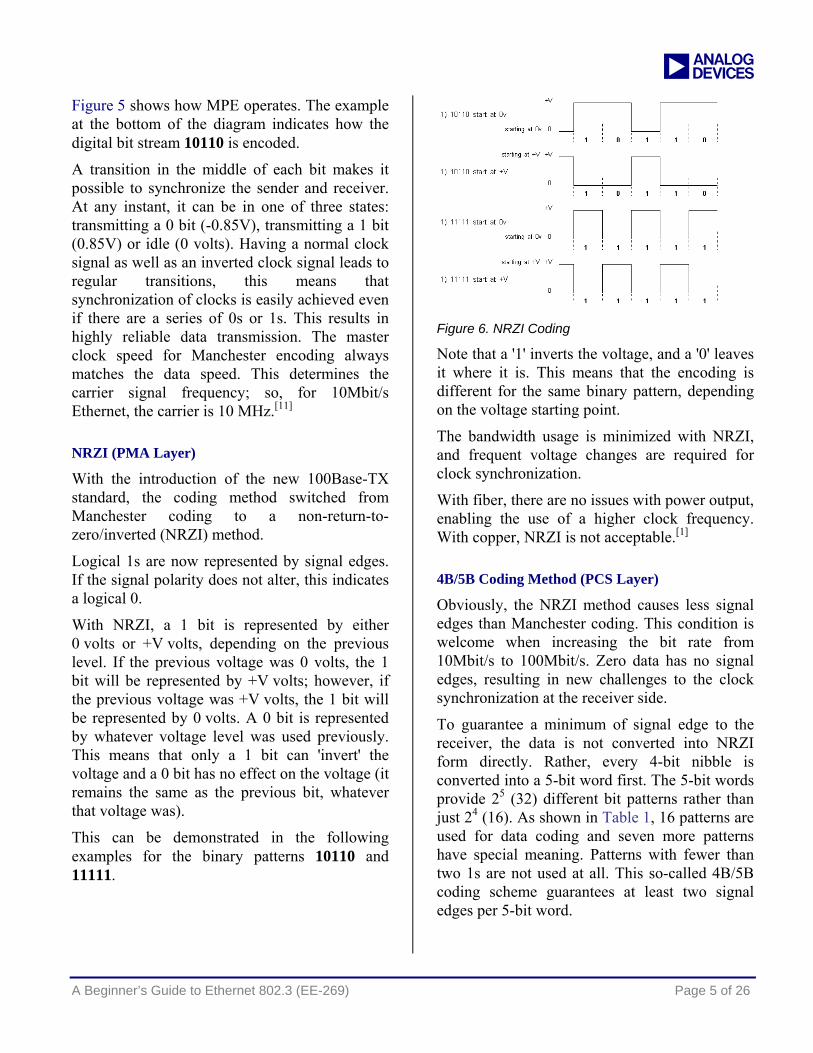
Figure 5 shows how MPE operates. The example at the bottom of the diagram indicates how the digital bit stream 10110 is encoded.
A transition in the middle of each bit makes it possible to synchronize the sender and receiver. At any instant, it can be in one of three states: transmitting a 0 bit (-0.85V), transmitting a 1 bit (0.85V) or idle (0 volts). Having a normal clock signal as well as an inverted clock signal leads to regular transitions, this means that synchronization of clocks is easily achieved even if there are a series of 0s or 1s. This results in highly reliable data transmission. The master clock speed for Manchester encoding always matches the data speed. This determines the carrier signal frequency; so, for 10Mbit/s Ethernet, the carrier is 10 MHz.[11]
NRZI (PMA Layer)
With the introduction of the new 100Base-TX standard, the coding method switched from Manchester coding to a non-return-to-zero/inverted (NRZI) method.
Logical 1s are now represented by signal edges. If the signal polarity does not alter, this indicates a logical 0.
With NRZI, a 1 bit is represented by either 0 volts or +V volts, depending on the previous level. If the previous voltage was 0 volts, the 1 bit will be represented by +V volts; however, if the previous voltage was +V volts, the 1 bit will be represented by 0 volts. A 0 bit is represented by whatever voltage level was used previously. This means that only a 1 bit can 'invert' the voltage and a 0 bit has no effect on the voltage (it remains the same as the previous bit, whatever that voltage was).
This can be demonstrated in the following examples for the binary patterns 10110 and 11111.
Figure 6. NRZI Coding
Note that a '1' inverts the voltage, and a '0' leaves it where it is. This means that the encoding is different for the same binary pattern, depending on the voltage starting point.
The bandwidth usage is minimized with NRZI, and frequent voltage changes are required for clock synchronization.
With fiber, there are no issues with power output, enabling the use of a higher clock frequency. With copper, NRZI is not acceptable.[1]
4B/5B Coding Method (PCS Layer)
Obviously, the NRZI method causes less signal edges than Manchester coding. This condition is welcome when increasing the bit rate from 10Mbit/s to 100Mbit/s. Zero data has no signal edges, resulting in new challenges to the clock synchronization at the receiver side.
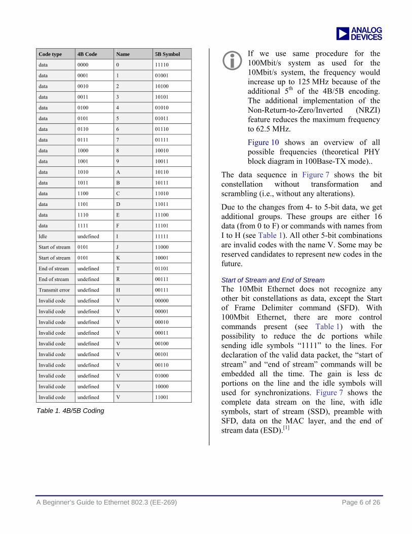
To guarantee a minimum of signal edge to the receiver, the data is not converted into NRZI form directly. Rather, every 4-bit nibble is converted into a 5-bit word first. The 5-bit words provide 25 (32) different bit patterns rather than just 24 (16). As shown in Table 1, 16 patterns are used for data coding and seven more patterns have special meaning. Patterns with fewer than two 1s are not used at all. This so-called 4B/5B coding scheme guarantees at least two signal edges per 5-bit word.
a
A Beginner’s Guide to Ethernet 802.3 (EE-269) Page 6 of 26
Code type 4B Code Name 5B Symbol
data 0000 0 11110
data 0001 1 01001
data 0010 2 10100
data 0011 3 10101
data 0100 4 01010
data 0101 5 01011
data 0110 6 01110
data 0111 7 01111
data 1000 8 10010
data 1001 9 10011
data 1010 A 10110
data 1011 B 10111
data 1100 C 11010
data 1101 D 11011
data 1110 E 11100
data 1111 F 11101
Idle undefined I 11111
Start of stream 0101 J 11000
Start of stream 0101 K 10001
End of stream undefined T 01101
End of stream undefined R 00111
Transmit error undefined H 00111
Invalid code undefined V 00000
Invalid code undefined V 00001
Invalid code undefined V 00010
Invalid code undefined V 00011
Invalid code undefined V 00100
Invalid code undefined V 00101
Invalid code undefined V 00110
Invalid code undefined V 01000
Invalid code undefined V 10000
Invalid code undefined V 11001
Table 1. 4B/5B Coding
If we use same procedure for the 100Mbit/s system as used for the 10Mbit/s system, the frequency would increase up to 125 MHz because of the additional 5th of the 4B/5B encoding. The additional implementation of the Non-Return-to-Zero/Inverted (NRZI) feature reduces the maximum frequency to 62.5 MHz.
Figure 10 shows an overview of all possible frequencies (theoretical PHY block diagram in 100Base-TX mode)..
The data sequence in Figure 7 shows the bit constellation without transformation and scrambling (i.e., without any alterations).
Due to the changes from 4- to 5-bit data, we get additional groups. These groups are either 16 data (from 0 to F) or commands with names from I to H (see Table 1). All other 5-bit combinations are invalid codes with the name V. Some may be reserved candidates to represent new codes in the future.
Start of Stream and End of Stream The 10Mbit Ethernet does not recognize any other bit constellations as data, except the Start of Frame Delimiter command (SFD). With 100Mbit Ethernet, there are more control commands present (see Table 1) with the possibility to reduce the dc portions while sending idle symbols “1111” to the lines. For declaration of the valid data packet, the “start of stream” and “end of stream” commands will be embedded all the time. The gain is less dc portions on the line and the idle symbols will used for synchronizations. Figure 7 shows the complete data stream on the line, with idle symbols, start of stream (SSD), preamble with SFD, data on the MAC layer, and the end of stream data (ESD).[1]

a
A Beginner’s Guide to Ethernet 802.3 (EE-269) Page 7 of 26
Figure 7. Bytes on the Line, 100Mbit/s
MLT3 and Scrambling (PMD Layer)
The 100Base-TX transfers data with Multilevel Threshold-3 (MLT3) mechanism at the line. Three values (+1, 0, and -.1) are possible to code from NRZI signal and vice versa. The benefit of the MLT3 method is to half the NRZI transfer frequency from 62.5 MHz to 31.25 MHz.
In 100Base-TX transmission requires scrambling to reduce the radiated emissions on the twisted-pair cable, but Scrambler and Descrambler are disabled for 10Base-T operation.[18]
The side-stream scrambler polynomials are generated by the Physical Medium Depend (PMD) and has the following equations
gM (x) = 1+ x13 + x33 for master
gM (x) = 1+ x20 + x33 for slave
The implementation of master and slave PHY side-stream scramblers is made possible by using a linear-feedback shift register. For an implementation of this feature, refer to the data sheet of your favorite PHY.[12]
Comparing Manchester Code, 4B/5B Code, and MLT-3
All bits will be transformed with NRZI, MLT-3, and scrambling methods; therefore, you cannot measure this (e.g., with an oscilloscope) at the line.
0 1 1 1 0 1 0 0
clock
bits
NRZI-Code
ManchesterCode
A
-A
0NRZIand MLT-3
Figure 8. Manchester vs. NRZI-Code [9]
The Manchester code changes its value after each bit of the signal. The NRZI code does the same with its limited subsequent numbers of zeros changes the bit deterministic. The 4B/5Bit coding method used only two subsequent zeros exempted “Start of Stream” (see Table 1).
The combination of the NRZI and MLT-3 methods reduces the frequency once more, so that the maximum frequency goes down to 31.25 MHz.
With the behavior of these coding methods, a clock recovery is always possible. Thus, for 10/100Mbit/s networks (Manchester or 4B/5B with MLT-3), no additionally clock sources are necessary.
10101010 10101010 10101011
7Bytes SFD
ESD
Data MAC layer
Data on the line
Preamble/SFD 7+1Byte
Dst-Addr 6Bytes
Data 46 - 1500 Byte
CRC 4Byte
Src-Addr 6Bytes
Lenght 2Bytes SSD
JK Idle Signal
Idle Signal
TR

a
A Beginner’s Guide to Ethernet 802.3 (EE-269) Page 8 of 26
CSMA/CD
CSMA/CD is supported by the PHY and is required for networking in case of multiple accesses.
CS = carrier sense
MA = multiple access
CD = Collision detection
Carrier sense controls the line if there is traffic. If CS detects the line as free, data transfer can be started.
If other devices started at the same time, MA is designed to yield a stable network. The Ethernet network was designed such that multiple accesses are normal.
CD detects this multiple access, waits a time (random number), and gives the command to restart the procedure of a new data transfer.
Modes: Half Duplex and Full Duplex
Half Duplex Half duplex is a mode of operation with CSMA/CD support of a local area network (LAN) in which Data Terminal Equipment (DTEs) contend for access to a shared medium. Multiple, simultaneous transmissions in a half-duplex mode CSMA/CD LAN result in interference, which requires resolution by the CSMA/CD access control protocol.
Full Duplex Full duplex is a mode of operation of a network or Physical Medium Attachment (PMA) that supports duplex transmission as defined in IEEE 100. Within the scope of this standard, this mode of operation allows for simultaneous communication between a pair of stations,
provided that the Physical Layer is capable of supporting simultaneous transmission and reception without interference (without CSMA/CD).
The different modes are described in these IEEE specifications:
Half-Duplex: 10 MBit/s (IEEE 802.3)
Full-Duplex: 100 MBit/s (IEEE 802.3u)
Full-Duplex: Gigabit-Ethernet (IEEE 802.3ab) is Full-Duplex transfer with all four pairs
Auto-Negotiation
The Auto-Negotiation function automatically configures the PHY to optimal link parameters based on the capabilities of its link partners.[15] The twisted-pair Auto-Negotiation system defined in Clause 28 of the standard 802.3-2002 has since been extended to include all three speeds of Ethernet supported over twisted-pair cable: 10Mbit/s 10Base-T, 100Mbit/s 100Base-TX and 1000 Mbit/s 1000Base-T. The physical signaling portion of all three twisted-pair systems uses the same Auto-Negotiation signaling standard. While Auto-Negotiation can be disabled on 10Base-T and 100Base-TX links, it is required on 1000Base-T systems since Gigabit Ethernet systems use Auto-Negotiation to establish the master-slave signal timing control required to make the link operational.
Figure 9. Link Pulses
With Auto-Negotiation in place, all three speeds of twisted-pair Ethernet can determine the common set of options supported between a pair of "link partners". Twisted-pair link partners can
One of the most common causes of performance issues on 10/100Mbit/s Ethernet links is when one port on the link operates at half-duplex while the other port operates at full-duplex.
FLP
NLP’s

a
A Beginner’s Guide to Ethernet 802.3 (EE-269) Page 9 of 26
use Auto-Negotiation to figure out the highest speed that they each support, for example, as well as automatically setting full-duplex operation if both ends support that mode.
Auto-Negotiation takes place using Fast Link Pulse (FLP) signals. These signals are a modified version of the Normal Link Pulse (NLP) signals used to verify link integrity. The FLP signals are generated automatically at power-up, or may be selected manually through the management interface to an Auto-Negotiation device. The FLP signals are used to send information about device capabilities. The Auto-Negotiation protocol contains rules for device configuration based on this information.[10]
Auto-Negotiation Priority If two Auto-Negotiation devices with multiple capabilities are connected together, they find their highest performance mode of operation based on a priority Table 2, because both variants are compatible with the first pulse.
The priorities are listed in Table 2 and are ranked from the highest to the lowest. The full-duplex mode of operation is given higher priority than the original (half-duplex) Ethernet, since a full-duplex system can send more data than a half-duplex link operating at the same speed. Therefore, if the devices at both ends of the link can support full-duplex operation, and if they also both support Auto-Negotiation of this
capability, they will automatically configure themselves for the higher performance full-duplex mode.
A 100Base-TX Full Duplex B 100Base-T4 C 100Base-TX D 10Base-T Full Duplex E 10Base-T
Table 2. Auto-Negotiation Priority Resolution
Theoretical Block Diagram of a PHY The MII and PHY signal chain includes some different frequencies and data transformations. Figure 10 shows all possible frequencies and all blocks of data changes as well. It is merely a theoretical drawing, but it is representative of the signal chain of a 100Base-TX data stream in general.
The Auto-Negotiation protocol contains a set of priorities which result in the devices selecting their highest common set of abilities. For instance, if both devices on the link can support 10Base-T and 100Base-TX, the Auto-Negotiation protocol at both ends will connect using the 100Base-TX mode instead of 10Base-T.[10]

a
A Beginner’s Guide to Ethernet 802.3 (EE-269)
Management
Collosion
4B/5Bencoder
Scramblerand PISO
MLT-3Converter
4B/5BDecoder
Descrambler andSIPO
Clock&Datarecovery
(NRZIConverter)
Auto-Negotiation
and Link
MLT-3Converter
RJ45magnetics
TXDriver
CSMA/CD
100BASE-TX Receiver
100BASE-TX Transmitter
RXDriver
MACM
II
MII 25MHz
by 4 bits
PISO = parallel in serial out
NRZIConverter
25MHz
by 5 bits 62,5MHz 31.25MHz
MLT
-331
.25M
Hz
31.25MHz62,5MHz
NRZI
MLT-3
MLT-3
MLT-3NRZI125MHz
25MHz
by 5 bits
125MHz
PHY
SIPO = serial in parallel out
Figure 10. Theoretical PHY Block Diagram in 100Base-TX Mode
Registers of a MII-Compatible PHY Each PHY has several registers for its configuration. The registers are split into IEEE-compliant registers and vendor-specific registers. For instance, the first 16 registers are compliant to IEEE, but it depends on the supported features how many registers are included. This is also valid for the vendor-specific register; this means that the number of the included registers depends on the supported functions of the device. The vendor-specific registers start from address 16 until address 32, in general.
The registers are accessible via MII Interface using the Station Management pins. It is a synchronous serial interface with a clock (MDC) and a data (MDIO) wire. For more information, refer to MII Interface later in this EE-Note.
LED The PHY can indicate the status of the system using LEDs. By setting the appropriate registers, the LEDs will show useful system information, (e.g., indications for Speed-, Link-, Transmit-, Receive-, Collision, Duplex Status, and so on).
RJ45 and Twisted-Pair Cable
The Medium Dependent Interface (MDI) shown in Figure 4 uses twisted-pair cable or optical cable as the transfer medium. The RJ45 jack in combination with twisted cable is widely used due to its suppleness, price, and future-proof of speed. The optical variant is more expensive because of its need for optical switches, optical cables, etc.
F
Some PHYs duplex these pins with the PHY address in order to reduce the pin count. In this case, internal logic figures out the PHY address during power-up/reset.
1: TX + 3: RX +
2: TX - 6: RX –
Page 10 of 26
igure 11. RJ45 Connector

a
A Beginner’s Guide to Ethernet 802.3 (EE-269) Page 11 of 26
RJ45 connectors are designed for full-duplex transfers, which means a simultaneously transfer of transmit and receive data. This is possible because the connector has two pairs of wires, and one pair is always needed for one direction (differential voltage principle). Figure 11 shows the RJ45 jack in detail.[9]
Crossover Cable A crossover cable is required for direct connection between two devices (e.g., server and client connection) without a switch. Figure 12 shows the pin and color description of the normal cable as well as the crossover cable. With these colors, it is easy to distinguish between normal and crossover cable. For instance, a direct connection between two PCs (or some connections of Hubs) requires a crossover cable. The wires are crossed, so a transfer interface can reach the receive interface, and vice versa.
Figure 12. Cross-Over Cable vs. Normal Cable
What are the Benefits of Using Twisted-Pair Cable? This system is based on the differential voltage principle. That means the data is split into two signals. The twisted-pair cables are the transport medium. At the end, a comparator circuit combines the signals together. The following equation shows that the noise will be abrogated.
Figure 13. Principle of Twisted-Pair Cable
((+data) +(+noise))-((-data)–(+noise))=2x data
The twisted-pair cable yields an amplified data signal, and noise does not influence the data quality.
Can the Same Twisted-Pair Cable be Used for 10Mbit and 100Mbit Ethernet? The Internet structure is designed to use twisted-pair cable for both 10Mbit/s and 100Mbit/s Ethernet networks. This is possible, because the protocols changed to 4/5 coding with additional NRZ-I and MLT-3 transforming for 100Mbit/s Ethernet, Therefore, the working frequencies went down to nominal 31.25 MHz on the line.
Magnetics
An isolation-magnetic for each RJ45 connector is required by the IEEE standard. This magnetic isolates and offsets the signal voltage from MAC and from RJ45 to protect the MAC and other devices (e.g., switches) from being damaged by high voltage at the line. Some RJ45 jacks have already included the magnetic. For example, HALO Electronics offers FastJack™ connectors with integrated high-performance magnetics. These connectors have a small industry-standard connector design and work on some EZ-KIT Lite daughter cards. Figure 14 shows the pin description of this RJ45 connector with integrated magnetics.[14]
&
+
-
0V – (+2.8V)
-2.8V– 0V

a
A Beginner’s Guide to Ethernet 802.3 (EE-269) Page 12 of 26
Figure 14. Magnetics of the RJ45 Connector (HALO FastJack™ Series)
Power over Ethernet PoE
Power over Ethernet (PoE) is adapted for systems in low-power designs (e.g., Webcams and sensors) and a specified maximum supply voltage of 48 V dc (IEEE802.3af). PoE systems contain the Power Sourcing Equipment (PSE) and Powered Device (PD) and have a recommended maximum cable length of 100 m. The maximal power consumption is 15.4 W with a maximal current of 350 mA for each consuming device. The cable type is recommended to CAT-5 with RJ45 jack. PoE is possible because the two pin pairs of the RJ45 jack are reserved in 10BaseT (10 MBit/s) and 100BaseTX (100 MBit/s) systems. These four pins will be used for PoE as shown in Figure 15.[9]
Figure 15. PoE Connection
Resistive Power Discovery Resistive power discovery is a method to protect the PDs while the PSE controls periodically the line for a 25K-ohm terminating resistor as well as the present current. If the minimum current is less than 5 mA-10 mA, the PSE recognizes this as unplugged PoE devices and stops the support of power immediately.
Classes State Power supply, PSE (max)
Take-off power, PD (max)
0 default 15,4W 0,44W – 12,95W
1 optional 4,0W 0,44W – 3,84W
2 optional 7,0W 3,84W – 6,49W
3 optional 15,4W 6,49W – 12,95W
Table 3. PoE Power Classes
MII Interface
The Media Independent Interface (MII) is an 18-pin interface and is designed for communications between PHY and MAC layers in 10Mbit and 100Mbit Ethernet networks. The transceiver (PHY) can be connected directly or with cables and connectors (maximum distance of 50 cm).
MII Connector: Size and Type: The standard describes a subminiature-D-connector for the MII, which has 40 pins and is 50 mm x 15 mm. Figure 16 shows this connector. For a detailed description of this connector, refer to IEC 1076-3-1001:1995.
Figure 16. Miniature-D MII Connector
Table 4 shows the pin descriptions of a subminiature-D connector.
1202140

a
A Beginner’s Guide to Ethernet 802.3 (EE-269) Page 13 of 26
Pin Signal Pin Signal Pin Signal Pin Signal
1 PWR 11 TX_ER 21 PWR 31 Gnd
2 MDIO 12 TX_CLK 22 Gnd 32 Gnd
3 MDC 13 TX_EN 23 Gnd 33 Gnd
4 RXD3 14 TXD3 24 Gnd 34 Gnd
5 RXD2 15 TXD2 25 Gnd 35 Gnd
6 RXD1 16 TXD1 26 Gnd 36 Gnd
7 RXD0 17 TXD0 27 Gnd 37 Gnd
8 RX_DV 18 COL 28 Gnd 38 Gnd
9 RX_CLK 19 CRS 29 Gnd 39 Gnd
10 RX_ER 20 PWR 30 Gnd 40 PWR
Table 4. MII Connector Pin Description
Figure 17. Description MII
The standard MII interfaces of an Ethernet MAC (Figure 17) has three blocks (Transmit, Receive, and Management). The Management block is used to configure the PHY only, the other blocks are used for data transfers, as defined in the 10BaseT (10 MBit/s) and 100BaseTX (100 MBit/s) standard.
The TX_CLK signal is generated by the PHY. The TXD[3:0] and TX_EN signals are generated by the Reconciliation sub-layer after every group of four data transactions from the MAC sub-layer to request the transmission of four data bits on the physical medium or to stop transmission. Synchronization between the PHY and the Reconciliation sub-layer is achieved by way of the RX_CLK signal (refer to IEEE802.3).
The data transfers between Ethernet MAC and external PHY are 4 bit (nibble) in each direction, and the clock frequencies (TCLK and RCLK) are:
10Mbit/s 2.5 MHz
100Mbit/s 25 MHz
The transceiver has two status signals for communications: Transmit Enable (TX_EN) and Transmit Error (TX_ER). These signals are shown in Table 5.
TX_EN TX_ER TXD[3:0] Description
0 0 0000 - 1111 Interframe gap
0 1 0000 - 1111 Reserve
1 0 0000 - 1111 Send data
1 1 0000 - 1111 Initiate send error
Table 5. Transmit Status Signals
On the other side, the receive interface has more status signals, as described in Table 6.
RX_EN RX_ER RXD[3:0] Description
0 0 0000 - 1111 Interframe gap
0 1 0000 - 1111 Interframe gap
0 1 0001 - 1101 reserved
0 1 1110 Error of the carrier
0 1 1111 reserved
1 0 0000 - 1111 normal data receive
1 1 0000 - 1111 error receive of data
Table 6. Receive Status Signals
TX_EN
TXD[3:0]
TX_ER
TX_CLK
COL
CSR
RX_DV
RXD[3:0]
RX_ER
RX_CLK
M I I
Data I/O (MDIO)
Data Clock (MDC)
Manage ment
receive
transmit

a
A Beginner’s Guide to Ethernet 802.3 (EE-269) Page 14 of 26
RMII (reduced MII) uses only two data lines for transmit (TXD[1:0]) and two for receive (RX[1:0]). This requires twice the transfer rate:
10Mbit/s 5 MHz
100Mbit/s 50 MHz
Protocol Structure
Overview of Layers
This section delves into the structure and description of the following layers:
MAC layer
IP layer
UDP layer
TCP layer
Figure 18. Header Structure and Preamble
To understand the Ethernet data stream, it is essential to know that each layer has its own structure of headers and data. All implemented layers analyze or generate the header and passes
this to the upper or lower layer, depending upon whether the stack stays in receive or transmit mode.
MAC Header IP Header TCP/UDP-Header DATA FCS data link layer
IP Header TCP/UDP-Header DATA network layer
UDP-Header DATA
TCP-Header DATA
transport layer
DATA
--------------------------------------------------------------------------------------------------------------------
--------------------------------------------------------------------------------------------------------------------
--------------------------------------------------------------------------------------------------------------------
application layer
respectively
--------------------------------------------------------------------------------------------------------------------
Preamble/SFD 7+1Byte
MAC Header
Data FCS IP Header
TCP/UDP Header SSD
JK Idle Signal
Idle Signal
TR
ESD
100Mbit physical layer

a
A Beginner’s Guide to Ethernet 802.3 (EE-269) Page 15 of 26
In transmit mode, the stack gets the data from the upper layer and builds its a header around this. Then it passes this information to the lower layer, which performs the same procedure as the upper layer, and so forth.
In receive mode, the layer gets data from the lower layer, analyzes it, extracts data, and passes it to the upper layer, and so on.
For the current layers, the gray fields are always data (see Figure 18). It’s yet describes with the header name because of the overview and comprehension.
Physical Layer
Figure 19 shows preamble length. It contains 8 bytes to prepare the data stream. The first 7 bytes provides the synchronization of the PHY and the 8th byte (SFD). The bit combination “11” signals the start of value data.
Figure 19. Preamble
MAC Header
Figure 20. MAC Header
Figure 20 describes the length of the MAC header. In the 14-byte MAC header, the first six bytes are the destination address, the second six bytes are the source address, and the last two bytes include the length or the type of service. Ethernet II uses this field for TYPE information (note that the IEEE802.3-2002 standard reserved this field for length information). The difference between these two frames is quite clear because numbers from 0-1500 are length numbers and are related to IEEE802.3-2002. Numbers above 1500 relate to Ethernet II. Table 7 provides an overview of popular protocols.
Ethernet-Type
Decimal Protocol
0-05DC 0-1500 Ethernet length
0600 1536 XEROX IDP
0800 2048 IP
0805 2053 X.25
0806 2054 ARP
8035 32821 RARP
809B 32923 AppleTalk
8137 33079 Novell
8138 33080 Novell
Table 7. Overview of the TYP/LENGTH Field in the MAC Header [13]
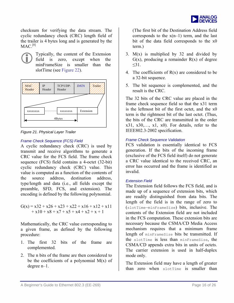
Trailer of the MAC Layer The Trailer field (Figure 21) contains the FCS Field and the Extension field. This includes the
In the physical layer, the DST field (MAC header) is preceded by a 7-byte preamble and a 1-byte Start of Frame Delimiter (SFD).
MAC Header
Preamble
TCP/UDP-Header
DATA Trailer
10101010 10101010 10101011
7Bytes SFD
MAC Header
IP Header
TCP/UDP-Header
DATA Trailer
LEN/TYP 2Byte
14Bytes
DST 6Byte SRC 6Byte
a
A Beginner’s Guide to Ethernet 802.3 (EE-269) Page 16 of 26
checksum for verifying the data stream. The cyclic redundancy check (CRC) length field of the trailer is 4 bytes long and is generated by the MAC.[8]
Typically, the content of the Extension field is zero, except when the minFrameSize is smaller than the slotTime (see Figure 22).
Figure 21. Physical Layer Trailer
Frame Check Sequence (FCS) Field A cyclic redundancy check (CRC) is used by transmit and receive algorithms to generate a CRC value for the FCS field. The frame check sequence (FCS) field contains a 4-octet (32-bit) cyclic redundancy check (CRC) value. This value is computed as a function of the contents of the source address, destination address, type/length and data (i.e., all fields except the preamble, SFD, FCS, and extension). The encoding is defined by the following polynomial.
G(x) = x32 + x26 + x23 + x22 + x16 + x12 + x11 + x10 + x8 + x7 + x5 + x4 + x2 + x + 1
Mathematically, the CRC value corresponding to a given frame, as defined by the following procedure:
1. The first 32 bits of the frame are complemented.
2. The n bits of the frame are then considered to be the coefficients of a polynomial M(x) of degree n–1.
(The first bit of the Destination Address field corresponds to the x(n–1) term, and the last bit of the data field corresponds to the x0 term.)
3. M(x) is multiplied by 32 and divided by G(x), producing a remainder R(x) of degree ≤31.
4. The coefficients of R(x) are considered to be a 32-bit sequence.
5. The bit sequence is complemented, and the result is the CRC.
The 32 bits of the CRC value are placed in the frame check sequence field so that the x31 term is the leftmost bit of the first octet, and the x0 term is the rightmost bit of the last octet. (Thus, the bits of the CRC are transmitted in the order x31, x30,…, x1, x0). For details, refer to the IEEE802.3-2002 specification.
Frame Check Sequence Validation FCS validation is essentially identical to FCS generation. If the bits of the incoming frame (exclusive of the FCS field itself) do not generate a CRC value identical to the received CRC, an error has occurred and the frame is identified as invalid.
Extension Field The Extension field follows the FCS field, and is made up of a sequence of extension bits, which are readily distinguished from data bits. The length of the field is in the range of zero to (slotTime–minFrameSize) bits, inclusive. The contents of the Extension field are not included in the FCS computation. These extension bits are necessary because the CSMA/CD Media Access mechanism requires that a minimum frame length of minFrameSize bits be transmitted. If the slotTime is less than minFrameSize, the CSMA/CD appends extra bits in units of octets. The carrier extension is used in half-duplex mode only.
The Extension field may have a length of greater than zero when slotTime is smaller than
MAC Header
IP Header
TCP/UDP-Header
DATA Trailer
xxxxxxxx
4Bytes
xxxxxxxx Extension

a
A Beginner’s Guide to Ethernet 802.3 (EE-269) Page 17 of 26
minFrameSize. The length of the Extension field will be zero under all other conditions. For
details, refer to the IEEE802.3-2002 specification.
Figure 22. Frame with Carrier Extension Invalid MAC Frame If the MAC frame meets any of the following conditions, it is considered to be invalid:
The frame length is inconsistent with the length value specified in the length/type field. If the length/type field contains a type value above 1536 (0x600), the frame length is assumed to be consistent with this field and should not be considered an invalid frame on this basis.
It is not an integral number of octets in length.
The bits of the incoming frame (exclusive of the FCS field itself) do not generate a CRC value identical to the one received. The contents of invalid MAC frames shall not be passed MAC Control sub-layers. The occurrence of invalid MAC frames may be communicated to network management.[12]
Figure 23. Bytes of Data Stream
Field Name min Size
max Size
min w/o Preamble
max w/o Preamble
Preamble 7 7
SFD 1 1
DST 6 6 6 6
SRC 6 6 6 6
Type/Length 2 2 2 2
Data 46 1500 46 1500
Checksum 4 4 4 4
Total 72 1526 64 1518
Table 8. Minimal and Maximal Byte Counts
The minimum size for a data packet sent over Ethernet 802.3u is 70 bytes, and the maximum size is 1524 bytes.
Figure 23 and Table 8 give an overview of the traffic on the line. The calculation of the minimum bytes is: 18 Bytes = MAC Header + Trailer
The maximum calculation, Min Traffic, is: 18Bytes + Datamin = 18Bytes + 46Bytes = 64Bytes
The maximum calculation, Max Traffic is: 18Bytes + Data max = 18Bytes + 1500Bytes = 1518Bytes
MAC Header
IP Header
TCP/UDP-Header
DATA Trailer
14Byte
46Byte(min) ---------- 1500Byte (max)
20Byte 24Byte DATA 4Byte
Preamble SFD DST SRC TYP/Length Data FCS Extension
minFrameSize
slotTime

a
A Beginner’s Guide to Ethernet 802.3 (EE-269) Page 18 of 26
Internet Layers
ARP (Address Resolution Protocol)
Level 3 of the OSI model also includes the ARP, which is one part of the basic network system. The ARP organizes groups of MAC addresses via a stack. The stack table contains the IP addresses with its familiar MAC-Addresses. The system administrator specifies how long the MAC addresses will be present (stay time). Stay time is limited in the stack and is normally a manner of two days. When this time is reached, the MAC addresses with its IP addresses will be deleted. By means of this behavior, the Stack is always minimized.
The basic function works as follows. If anybody starts a request with a “URL”, the MAC address is not usually well-known. With the assistance of the name server, the “URL” is dissolved to its IP address, but the header still does not contain the MAC address; instead, the value 0xFFFFFF is placed on its place. Next, the router starts a Broadcast to the sub-level where the IP address shows, and each device takes this request in these sub-levels. Only the right devices recognize this request (because of the fitted IP address) and send back its IP and MAC address.[5]
ICMP (Internet Control Message Protocol)
Typically, ICMP messages report errors in the processing of datagrams and use the basic support of IP as if it were a higher level protocol. However, ICMP is actually an integral part of IP, and must be implemented by every IP module The ICMP is used from gateways to hosts (and between hosts) to report errors and make routing suggestions.[3]
IP (Internet Protocol)
Figure 24. IP Header
Version: 4 bits
The Version field indicates the format of the Internet header. This document shows version 4.
IHL: 4 bits
Internet Header Length is the length of the Internet header in 32-bit words; thus, it points to the beginning of the data. Note that the minimum value for a correct header is 5.
Type of Service: 8 bits
Type of Service provides an indication of the abstract parameters of the quality of service desired. These parameters are to be used to guide the selection of the actual service parameters when transmitting a datagram through a particular network.
Total Length: 16 bits
Total Length is the length of the datagram, measured in octets, including Internet header and data. This field allows the length of a datagram to be up to 65535 octets. Such long datagrams are impractical for most hosts and networks. All hosts must be prepared to accept datagrams of up to 576 octets (whether they arrive whole or in
IP Header TCP/UDP-Header DATA
20Byte 20Byte Data
Version IHL Type of Service
Total Length
Indentification Flags Fragment Offset
Time to Live Protocol Header Checksum
Source Address
Destination Address
0 32 Bit 16
a
A Beginner’s Guide to Ethernet 802.3 (EE-269) Page 19 of 26
fragments). It is recommended that hosts only send datagrams larger than 576 octets if they have assurance that the destination is prepared to accept the larger datagrams.
Identification: 16 bits
This is an identifying value assigned by the sender to aid in assembling the fragments of a datagram.
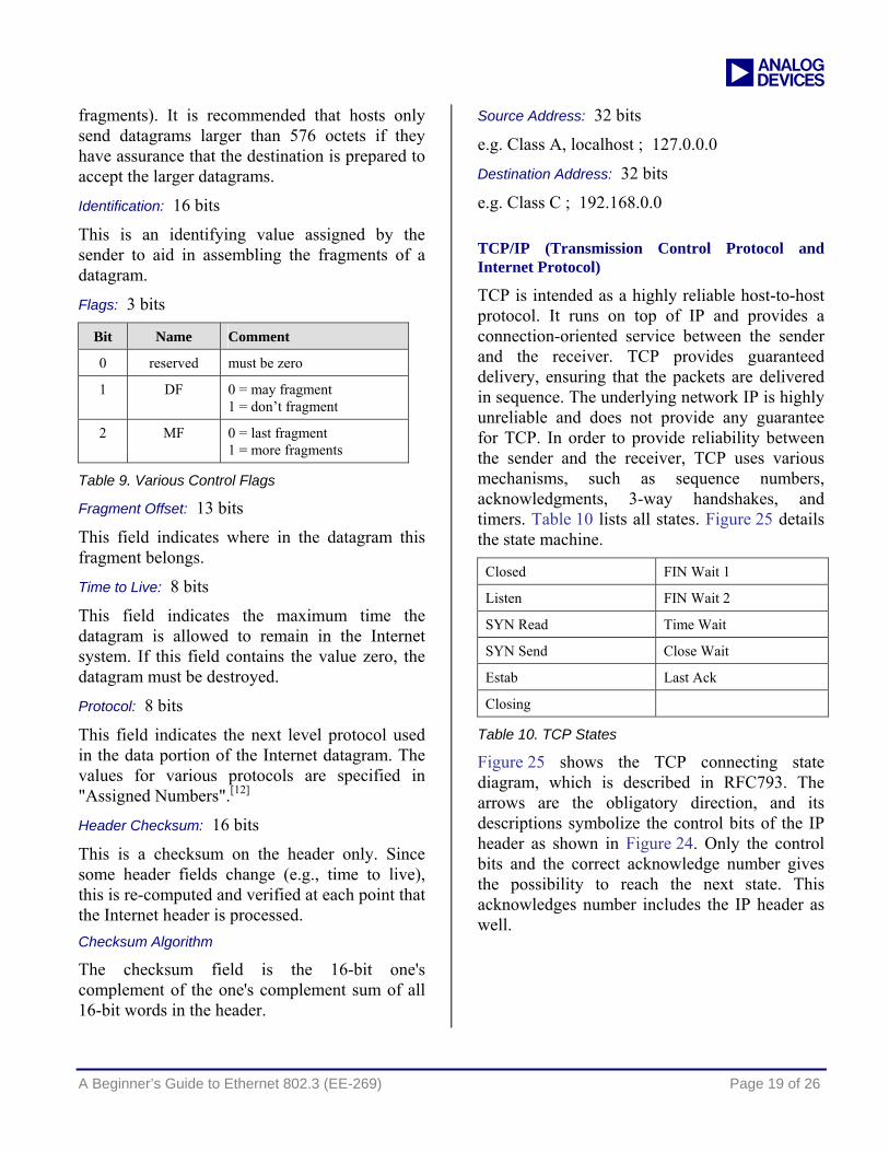
Flags: 3 bits
Bit Name Comment
0 reserved must be zero
1 DF 0 = may fragment 1 = don’t fragment
2 MF 0 = last fragment 1 = more fragments
Table 9. Various Control Flags
Fragment Offset: 13 bits
This field indicates where in the datagram this fragment belongs.
Time to Live: 8 bits
This field indicates the maximum time the datagram is allowed to remain in the Internet system. If this field contains the value zero, the datagram must be destroyed.
Protocol: 8 bits
This field indicates the next level protocol used in the data portion of the Internet datagram. The values for various protocols are specified in "Assigned Numbers".[12]
Header Checksum: 16 bits
This is a checksum on the header only. Since some header fields change (e.g., time to live), this is re-computed and verified at each point that the Internet header is processed. Checksum Algorithm The checksum field is the 16-bit one's complement of the one's complement sum of all 16-bit words in the header.
Source Address: 32 bits
e.g. Class A, localhost ; 127.0.0.0
Destination Address: 32 bits
e.g. Class C ; 192.168.0.0
TCP/IP (Transmission Control Protocol and Internet Protocol)
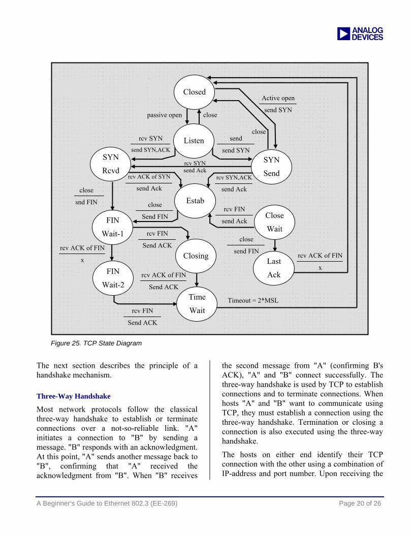
TCP is intended as a highly reliable host-to-host protocol. It runs on top of IP and provides a connection-oriented service between the sender and the receiver. TCP provides guaranteed delivery, ensuring that the packets are delivered in sequence. The underlying network IP is highly unreliable and does not provide any guarantee for TCP. In order to provide reliability between the sender and the receiver, TCP uses various mechanisms, such as sequence numbers, acknowledgments, 3-way handshakes, and timers. Table 10 lists all states. Figure 25 details the state machine.
Closed FIN Wait 1
Listen FIN Wait 2
SYN Read Time Wait
SYN Send Close Wait
Estab Last Ack
Closing
Table 10. TCP States
Figure 25 shows the TCP connecting state diagram, which is described in RFC793. The arrows are the obligatory direction, and its descriptions symbolize the control bits of the IP header as shown in Figure 24. Only the control bits and the correct acknowledge number gives the possibility to reach the next state. This acknowledges number includes the IP header as well.
a
A Beginner’s Guide to Ethernet 802.3 (EE-269) Page 20 of 26
Figure 25. TCP State Diagram
The next section describes the principle of a handshake mechanism.
Three-Way Handshake
Most network protocols follow the classical three-way handshake to establish or terminate connections over a not-so-reliable link. "A" initiates a connection to "B" by sending a message. "B" responds with an acknowledgment. At this point, "A" sends another message back to "B", confirming that "A" received the acknowledgment from "B". When "B" receives
the second message from "A" (confirming B's ACK), "A" and "B" connect successfully. The three-way handshake is used by TCP to establish connections and to terminate connections. When hosts "A" and "B" want to communicate using TCP, they must establish a connection using the three-way handshake. Termination or closing a connection is also executed using the three-way handshake.
The hosts on either end identify their TCP connection with the other using a combination of IP-address and port number. Upon receiving the
FIN
Wait-2
Closing
SYN
Send
rcv FIN
Send ACK
rcv ACK of FIN
Send ACK
rcv FIN
Send ACK
close
Send FIN
rcv ACK of FIN
x
rcv ACK of FIN
x
rcv FIN
send Ack
rcv SYN,ACK
send Ack
rcv ACK of SYN
send Ack
rcv SYN
send SYN,ACK
passive open
close
send FIN
Active open
send SYN
Timeout = 2*MSL
rcv SYN send Ack
send
send SYN
close
close
Last
Ack
Close
Wait FIN
Wait-1
Time
Wait
Closed
SYN
Rcvd
Estab
Listen
close
snd FIN

a
A Beginner’s Guide to Ethernet 802.3 (EE-269) Page 21 of 26
first segment from the remote host, a table entry is created, containing all the parameters necessary to identify the connection.
Connection Setup
TCP uses the three-way-handshake to set up a successful connection. When host "A" wants to open a connection to host "B", "A" sends an initial segment to "B". This initial segment has the Initial Sequence Number (ISN) required by "B" to send data to "A". This initial segment is identified by the SYN bit set to 1 in the TCP header. If the SYN bit is set, the 32-bit sequence number in the header is interpreted as the ISN. In all other cases (when the SYN bit is not set), the 32-bit sequence number identifies the sequence number of the first data byte contained in that segment. Upon receiving the SYN from "A", "B" must respond with another SYN, and acknowledge the SYN sent by "A". This is indicated by SYN+ACK in the state machine diagram.
Figure 26. Initial Connection Establishment
Connection Release
Connection release in TCP also uses the three-way handshake. Connection release uses the FIN in place of the SYN.
Figure 27. Connection Release in TCP
Some TCP/IP stacks go a different way for releasing the connection while sending a RESET bit. This cause the command to release this connection and move immediately to CLOSED state again.
TCP Timers
Timers are closely knit with the TCP states. Some values, but not all, are specified by the RFC. Some timers are left open to individual implementations. This document will examine timers relevant to the discussion, including timers at connection establishment and timers at connection termination.
Connection Establishment Timer
This timer is associated with the opening of a connection. It is started when the SYN is sent during the initial connection setup. In most TCP implementations, the value of this timer is set to 75 seconds. If a time-out occurs, the connection is aborted.
FIN_WAIT Timer
A FIN_WAIT_2 timer is started when a transition from the FIN_WAIT_1 state to the FIN_WAIT_2 state occurs. The value of this timer is 10 minutes. A TCP segment with a FIN bit set is expected in the FIN_WAIT_2 state. If a packet with a FIN bit set is received, the timer is cancelled. On expiration of the timer, it is restarted with a value of 75 seconds. If no packet
a
A Beginner’s Guide to Ethernet 802.3 (EE-269) Page 22 of 26
with the FIN bit arrives within this period, the connection is dropped.
TIME_WAIT Timer
A Time-wait timer is started when the connection enters the TIME-WAIT state. This allows the removal from the network of all the segments in transit. The value of the timer is usually set to 2 minutes. On expiration of the timer, the connection is terminated.
KEEP_ALIVE Timer
Usually, TCP does not transmit anything over the connection when there is no data to send. There is no way of distinguishing this silence from the case when the connection is broken. A keep-alive timer can be set to permit TCP to periodically check whether the other end of the connection is still active. The default value of this timer is 2 hours. After the timer expiration, probes are sent to the remote end. If the remote does not respond to the probes, the connection is dropped.
Problems with the TCP State Machine The TCP state machine is shown in Figure 25 with a fixed state for all connection. Each connection logically starts in the CLOSED state, and makes transitions as shown in the diagram. After the connection is terminated, TCP returns to the CLOSED state. For a detailed description of the state machine, refer to RFC 793. It is easy to exploit a few flaws in the state machines, and create denial-of-service attacks. All denial-of-service attacks try to stall the TCP state machine in a particular state, either indefinitely or for a finite time.[4]
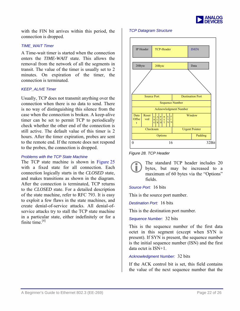
TCP Datagram Structure
Figure 28. TCP Header
Source Port: 16 bits
This is the source port number.
Destination Port: 16 bits
This is the destination port number.
Sequence Number: 32 bits
This is the sequence number of the first data octet in this segment (except when SYN is present). If SYN is present, the sequence number is the initial sequence number (ISN) and the first data octet is ISN+1.
Acknowledgment Number: 32 bits
If the ACK control bit is set, this field contains the value of the next sequence number that the
The standard TCP header includes 20 bytes, but may be increased to a maximum of 60 bytes via the “Options” fields.
Source Port Destination Port
Sequence Number
Acknowledgment Number
Data Offse
t
Reserved
Window
Checksum Urgent Pointer
Options Padding
IP Header TCP-Header DATA
20Byte 20Byte Data
32Bit 0 16
URG
ACK
PSH
RST
SYN
FIN
a
A Beginner’s Guide to Ethernet 802.3 (EE-269) Page 23 of 26
sender of the segment expects to receive. Once a connection is established, this is always sent.
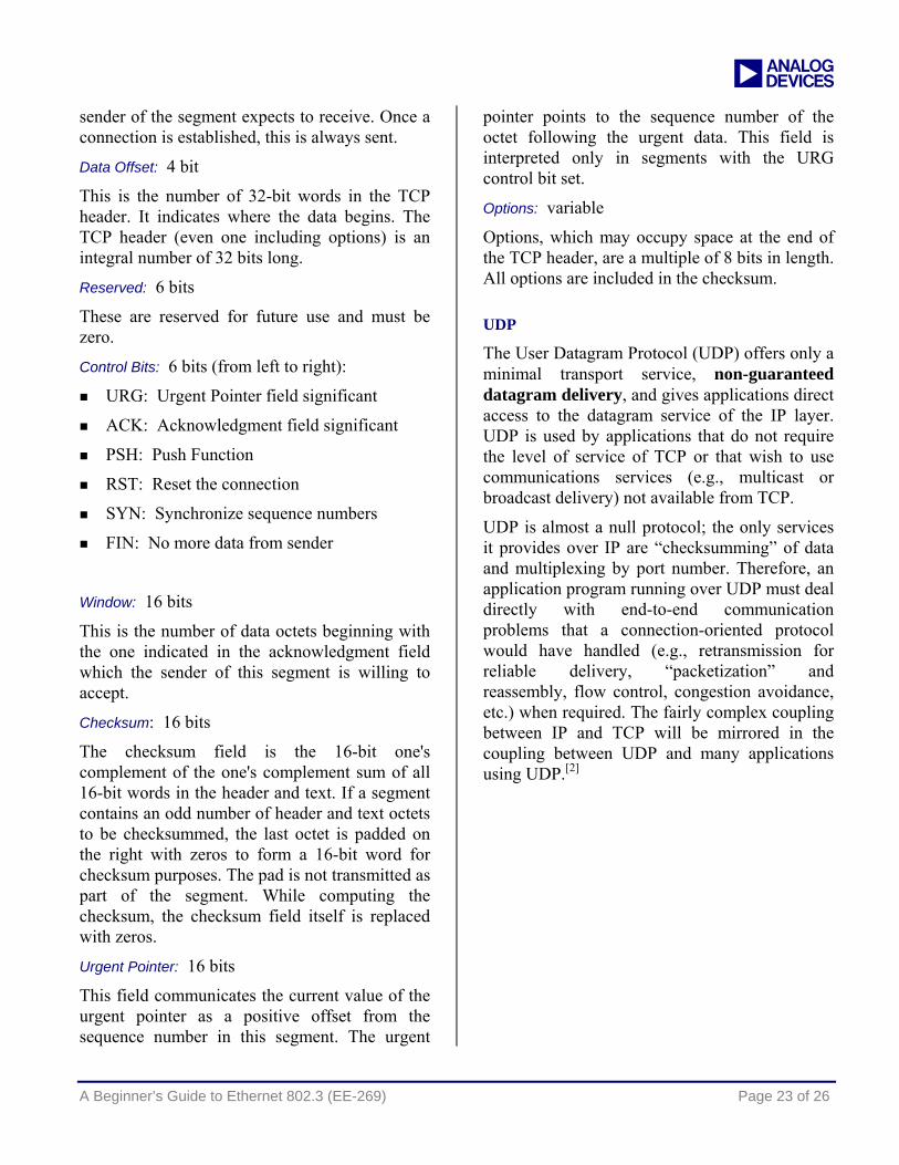
Data Offset: 4 bit
This is the number of 32-bit words in the TCP header. It indicates where the data begins. The TCP header (even one including options) is an integral number of 32 bits long.
Reserved: 6 bits
These are reserved for future use and must be zero.
Control Bits: 6 bits (from left to right):
URG: Urgent Pointer field significant
ACK: Acknowledgment field significant
PSH: Push Function
RST: Reset the connection
SYN: Synchronize sequence numbers
FIN: No more data from sender
Window: 16 bits
This is the number of data octets beginning with the one indicated in the acknowledgment field which the sender of this segment is willing to accept.
Checksum: 16 bits
The checksum field is the 16-bit one's complement of the one's complement sum of all 16-bit words in the header and text. If a segment contains an odd number of header and text octets to be checksummed, the last octet is padded on the right with zeros to form a 16-bit word for checksum purposes. The pad is not transmitted as part of the segment. While computing the checksum, the checksum field itself is replaced with zeros.
Urgent Pointer: 16 bits
This field communicates the current value of the urgent pointer as a positive offset from the sequence number in this segment. The urgent
pointer points to the sequence number of the octet following the urgent data. This field is interpreted only in segments with the URG control bit set.
Options: variable
Options, which may occupy space at the end of the TCP header, are a multiple of 8 bits in length. All options are included in the checksum.
UDP
The User Datagram Protocol (UDP) offers only a minimal transport service, non-guaranteed datagram delivery, and gives applications direct access to the datagram service of the IP layer. UDP is used by applications that do not require the level of service of TCP or that wish to use communications services (e.g., multicast or broadcast delivery) not available from TCP.
UDP is almost a null protocol; the only services it provides over IP are “checksumming” of data and multiplexing by port number. Therefore, an application program running over UDP must deal directly with end-to-end communication problems that a connection-oriented protocol would have handled (e.g., retransmission for reliable delivery, “packetization” and reassembly, flow control, congestion avoidance, etc.) when required. The fairly complex coupling between IP and TCP will be mirrored in the coupling between UDP and many applications using UDP.[2]
a
A Beginner’s Guide to Ethernet 802.3 (EE-269) Page 24 of 26
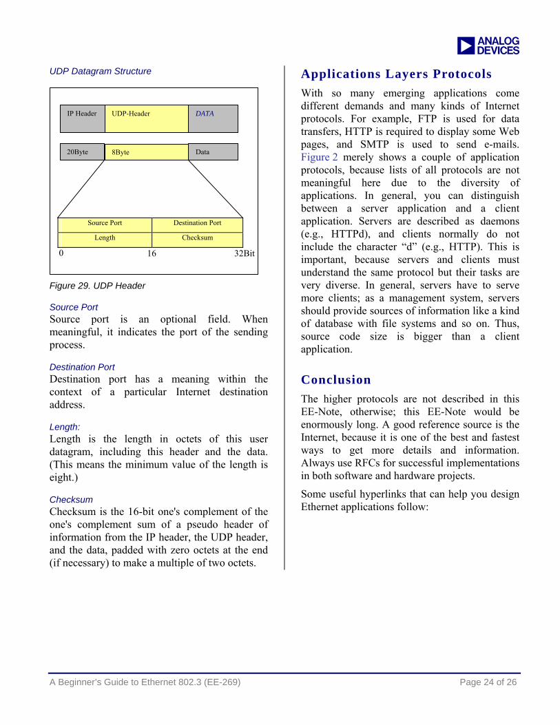
UDP Datagram Structure
Figure 29. UDP Header
Source Port Source port is an optional field. When meaningful, it indicates the port of the sending process.
Destination Port Destination port has a meaning within the context of a particular Internet destination address.
Length: Length is the length in octets of this user datagram, including this header and the data. (This means the minimum value of the length is eight.)
Checksum Checksum is the 16-bit one's complement of the one's complement sum of a pseudo header of information from the IP header, the UDP header, and the data, padded with zero octets at the end (if necessary) to make a multiple of two octets.
Applications Layers Protocols With so many emerging applications come different demands and many kinds of Internet protocols. For example, FTP is used for data transfers, HTTP is required to display some Web pages, and SMTP is used to send e-mails. Figure 2 merely shows a couple of application protocols, because lists of all protocols are not meaningful here due to the diversity of applications. In general, you can distinguish between a server application and a client application. Servers are described as daemons (e.g., HTTPd), and clients normally do not include the character “d” (e.g., HTTP). This is important, because servers and clients must understand the same protocol but their tasks are very diverse. In general, servers have to serve more clients; as a management system, servers should provide sources of information like a kind of database with file systems and so on. Thus, source code size is bigger than a client application.
Conclusion The higher protocols are not described in this EE-Note, otherwise; this EE-Note would be enormously long. A good reference source is the Internet, because it is one of the best and fastest ways to get more details and information. Always use RFCs for successful implementations in both software and hardware projects.
Some useful hyperlinks that can help you design Ethernet applications follow:
Source Port Destination Port
Length Checksum
IP Header UDP-Header DATA
20Byte 8Byte Data
0 16 32Bit

a
A Beginner’s Guide to Ethernet 802.3 (EE-269) Page 25 of 26
References [1] Data Encoding Techniques (http://www.rhyshaden.com/encoding.htm). Rhys B Haden, East Sussex.
[2] User Datagram Protocol (RFC 768). Aug 1980. J. Postel ISI 28.
[3] Internet Control Message Protocol (RFC 792). Sep 1981. J. Postel, Network Working Group.
[4] Transmission Control Protocol (RFC 793). Sep 1981. Information Sciences Institute, University of Southern California.
[5] An Ethernet Address Resolution Protocol (RFC 826). Nov 1982. David C. Plummer, Network Working Group.
[6] TCP/IP Security (http://www.linuxsecurity.com/resource_files/documentation/tcpip-security.html). Guardian Digital, Inc.
[7] RFC Source Book (http://www.networksorcery.com/enp/default0602.htm). Network Sorcery, Inc.
[8] Ethernet References (http://www.geocities.com/SiliconValley/Haven/4824/ethernet.html). William F. Alexander.
[9] Grundlagen Computernetzwerke (http://www.netzmafia.de/skripten/netze/). Jürgen Plate, University of Applied Sciences, Munich.
[10] Auto-Negotiation (http://www.ethermanage.com/ethernet/autoneg.html). Charles Spurgeon, Bellereti.
[11] Principles of Data Communications: Manchester Phase Encoding (http://www.it.jcu.edu.au/Subjects/cp3070/2002-2/resources/Lectures/2_DirectLinkNetworksNotes-2.pdf). School of Information Technology, James Cook University.
[12] IEEE Std 802.3-2002 Standard for Information Technology. IEEE Standards Association.
[13] Ethernet. Jan 2002. Jörg Rech, Verlag Heinz Heise.
[14] FastJack™ Single Port 10/100BASE-TX RJ45 Connectors. Rev 7/03. Halo Electronics. Inc.
[15] LAN83C185 Datasheet. Rev 0.8, Nov 2004. SMSC.
[16] ADSP-BF537 Blackfin Processor Hardware Reference. Prelim Rev 1.1, Jan 2005. Analog Devices Inc.
[17] Ethernet Network Interface for ADSP-BF535 Blackfin Processors (EE-214). Dec 2003. Analog Devices Inc.
[18] L80227 10BASE-T/100BASE-TX Ethernet PHY Technical Manual. Oct 2002. LSI Logic Corporation.
Network Sniffer
This tool shows exactly the data of the networking traffic. It is ideal for people working with binaries.
- ETHEREAL
o http://www.ethereal.com , a free Windows und Unix software
- TCPDUMP
o http://www.tcpdump.org , a free network analyzer for Unix
- WINDUMP
o http://netgroup-serv.polito.it/windump/ , a free version of tcpdump for Windows machines
- ANALYZER
o http://analyzer.polito.it , a free Windows software (Netgroup, Pilotecnico di Torino)

a
A Beginner’s Guide to Ethernet 802.3 (EE-269) Page 26 of 26
RFC Source Books
These web pages are very useful for searching RFCs. Normally, you will find a small description of each RFC and a download .TXT file of the original version.
o http://www.rfc-editor.org o http://www.networksorcery.com
Figures and Tables References
Figures 1 - Ethernet History
2 - Comparison between OSI and TCP/IP Models
3 - Ethernet History
4 - PHY and MAC Layer 100-Mbit Network
5 - Manchester Phase Encoding
6 - NRZI Coding
7 - Bytes on the Line, 100Mbit/s
8 - Manchester vs. NRZI-Code [9]
9 - Link Pulses
10 -Theoretical PHY Block Diagram in 100Base-TX Mode
11- RJ45 Connector
12 - Cross-Over Cable vs. Normal Cable
13 - Principle of Twisted-Pair Cable
14 - Magnetics of the RJ45 Connector (HALO FastJack™ Series)
15 - PoE Connection
16 - Miniature-D MII Connector
17 - Description MII
18 - Header Structure and Preamble
19 -Preamble
20 -MAC Header
21 - Physical Layer Trailer
22 - Frame with Carrier Extension
23 - Bytes of Data Stream
24 - IP Header
25 - TCP State Diagram
26 - Initial Connection Establishment
27 - Connection Release in TCP
28 - TCP Header
29 - UDP Header
Tables 1 - 4B/5B Coding
2 - Auto-Negotiation Priority Resolution
3 - PoE Power Classes
4 - MII Connector Pin Description
5 - Transmit Status Signals
6 - Receive Status Signals
7 - Overview of the TYP/LENGTH Field in the MAC Header [13]
8 - Minimal and Maximal Byte Counts
9 - Various Control Flags
Document History
Revision Description
Rev 1 – June 06, 2005 by R. Neuhaus
Initial Release