Embed Size (px)
Citation preview

Edwin Philips [email protected] Home:435-787-8617 Work435-792-8106
September 27, 2010
Dr. Donald Cripps Electrical and Computer Engineering Department Utah State University
Dear Dr. Cripps,
Please find attached the final design report for miniGreen: a small, efficient greenhouse system,
capable of monitoring for light and temperature, and (to a limited degree) moisture conditions.
This report includes detailed hardware and component specifications, with appropriate drawings, and
schematics. Also included is initial cost analysis, including, projected consumable costs, based on initial
trials.
I am satisfied with the outcome of this project, given the time constraints imposed. I look forward to
continued improvement of the device as I proceed through the live trial period.
Sincerely,
Edwin Philips

miniGreen: a portable, highly efficient, miniature greenhouse for economic production of common salad vegetables
by
Edwin C. Philips
A final design report for ECE4850, in partial fulfillment of the requirements for the degree
Of
Bachelor of Science
In
Computer Engineering
Instructor Approval ______________________________ ___________ Donald Cripps Date Electrical and Computer Engineering Department Utah State University

i
Abstract
This paper introduces a semi-portable, economical, indoor gardening solution. The need for this project is demonstrated through a brief review of recent economic and food safety headlines, which establish the value of, and the primary drivers of interest in this project.
This paper presents the complete design process for this project, including the problem definition, identification of key operational parameters, component selection, design and construction. Also included is documentation of the testing results to date. The system appears to perform as desired, within the specified budget constraints. Extended testing will be necessary to determine conclusively if the system successfully produces sufficient produce to generate value for the end user.
Finally, an analysis of lessons learned, and next steps is provided, giving a overview of possible improvements to the effectiveness of the system, while still maintaining the necessary low cost required to make the solution practical.

ii
Contents Abstract .......................................................................................................................................................... i
List of Tables ................................................................................................................................................ iv
List of Figures ................................................................................................................................................ v
Acknowledgments ........................................................................................................................................ vi
1. Introduction .............................................................................................................................................. 1
1.1 Subject and Purpose ........................................................................................................................... 1
1.2 Problem Statement ............................................................................................................................. 1
1.3 Design Objectives ................................................................................................................................ 3
1.4 Summary of Results ............................................................................................................................ 3
2. Review of Conceptual and Preliminary Designs........................................................................................ 3
2.1 Problem Analysis ................................................................................................................................. 3
2.2 System Requirements and Specifications ........................................................................................... 4
2.2.1 Physical Criteria: .................................................................................................................... 5
2.2.2 Operational criteria: ..................................................................................................................... 6
2.3 Engineering Approach ......................................................................................................................... 7
3. Basic Solution Description ......................................................................................................................... 8
3.1 Physical Structure................................................................................................................................ 8
3.1.1 Base .............................................................................................................................................. 8
3.1.2 Frame and Housing ...................................................................................................................... 9
3.1.3 Electronics mount ........................................................................................................................ 9
3.2 Electronics System .............................................................................................................................. 9
3.2.1 Microcontroller .......................................................................................................................... 10
3.2.2 Light Sensor ................................................................................................................................ 11
3.2.3 Temperature Sensor .................................................................................................................. 11
3.2.4 Moisture Sensor ......................................................................................................................... 11
3.2.5 Power Controller ........................................................................................................................ 12
3.2.6 User Interface............................................................................................................................. 12
4. Detailed Design ....................................................................................................................................... 13
4.1 Physical Structure.............................................................................................................................. 13
4.1.1 Base ............................................................................................................................................ 14
4.1.2 Frame ......................................................................................................................................... 15

iii
4.1.3 Housing ...................................................................................................................................... 18
4.1.4 Electronics Mount ...................................................................................................................... 19
4.2 Electronic Systems ............................................................................................................................ 20
4.2.1 Microcontroller .......................................................................................................................... 20
4.2.2 Light Sensor ................................................................................................................................ 21
4.2.3 Temperature Sensor .................................................................................................................. 23
4.2.4 Moisture Sensor ......................................................................................................................... 24
4.2.5 Power Controller Switches ......................................................................................................... 29
4.2.6 User Interface............................................................................................................................. 30
4.2.7 Option: Clock .............................................................................................................................. 30
4.2.8 Option: Data Logging ................................................................................................................. 30
5. Project Implementation .......................................................................................................................... 31
6. Final Scope of Work Statement .............................................................................................................. 32
7. Other Issues ............................................................................................................................................ 33
8. Cost Estimation ....................................................................................................................................... 34
9. Project Management Summary .............................................................................................................. 35
10. Conclusion ............................................................................................................................................. 36
References .................................................................................................................................................. 37
Appendix A: An Alternative, Multi-menu User Interface Design ................................................................ 38

iv
List of Tables
Table 1. Analysis of Produce Costs……………………………………………..……………………………………..…..4
Table 2. Estimated Power Consumption for Proposed Solution…………………………………………..…5
Table 3. Wiring Specifications……..……………………………………………..………………………………………..17
Table 4. Common Light Levels for Various Room Types…………..…………………………………………...22
Table 5. Voltage induced by the soil moisture meter at various meter levels…………………..…..25
Table 6. Table of observed Arduino values and selected user values at various Lux levels …..31
Table 7. Cost broken down by subassembly………………………………………………………………………....34
Table 8. Tasks and Status………………………………………………………………………………..…………………....35
Table 9. Gantt Chart…………………………………..………………………………………………………………………...35

v
List of Figures
Figure 1. Economic headlines ....................................................................................................................... 1 Figure 2. Environment headlines .................................................................................................................. 2 Figure 3. Food Safety headlines .................................................................................................................... 2 Figure 4. System Block Diagram .................................................................................................................. 10 Figure 5. User Interface - conceptual drawing ............................................................................................ 12 Figure 6. User interface - operational diagram ........................................................................................... 13 Figure 7. The assembled base, holding a planter ....................................................................................... 14 Figure 8. the assembled base, with a second section used as a stand ....................................................... 14 Figure 9. Frame assembly diagram ............................................................................................................. 16 Figure 10. Frame wiring diagram ................................................................................................................ 17 Figure 11. The assembled frame, installed on the base ............................................................................. 18 Figure 12. Template for cutting the housing .............................................................................................. 18 Figure 13. miniGreen with housing installed Figure 14. Housing pulled back to reveal interior ...... 19 Figure 15. Electronics mount: Front view showing installed electronics (left) and partial rear view, showingJ-hook installation to frame (right) ................................................................................................ 20 Figure 16. The Arduino microcontroller...................................................................................................... 21 Figure 17. Wiring diagram for light sensor ................................................................................................. 23 Figure 18. LM335 Circuit ............................................................................................................................. 24 Figure 19. Front of Soil moisture tester (left) and back, with cover removed to show modification to interface with Arduino. (right) .................................................................................................................... 24 Figure 20. Graph of soil moisture tester output ......................................................................................... 25 Figure 21. Moisture sensor schematic ........................................................................................................ 26 Figure 22. Irrigation Sysytem construction and installation. ...................................................................... 27 Figure 23. Soda bottle with PVC thread assembly ...................................................................................... 28 Figure 24. Soda bottle reservior attached to frame ................................................................................... 28 Figure 25. S101S06V power controller implementation ............................................................................ 29 Figure 26. Alternative multi-menu design .................................................................................................. 38

vi
Acknowledgments
I would like to thank Dr. Don Cripps for his advice and encouragement. Dr. Cripps was a tremendous resource with respect to the gardening aspect, as well as the engineering aspect of this project.
Thanks to Dr. Cripps and Dr. Paul Wheeler for their wisdom, insight, which they so willingly shared, and which allowed me to expand my vision of the project, as well as identify and resolve potential roadblock to the success of the project.
I also wish to thank Laura Vernon for her guidance on the development of the documentation associated with his project. She greatly improved the quality of my work.
Special thanks go to Dr. Todd Moon, Kathy Bayn, Isobel Roskelley, Dr. Eric Rowley, Dr. David Brown, and the many other USU staff and Faculty members, who have been so willing to work with me in respect to my academic progress. Today is possible only because of their devotion to my success.
Thanks to my Parents for teaching me integrity, perseverance, and excellence, through both word and deed. Thanks to my wife and children, who have sacrificed much for my academic pursuits.

1
1. Introduction
This Section introduces the miniGreen project. It establishes the purpose of and justification for the project, and briefly examines the design objectives and results summary.
1.1 Subject and Purpose This report covers the design and construction of miniGreen: a small, economical, autonomous indoor gardening
system. This project was undertaken to demonstrate the feasibility of constructing an affordable and economically
feasible indoor greenhouse solution, using readily available materials.
1.2 Problem Statement The current convergence of economic and environmental concerns, illustrated by the headlines in Figures 1 and 2
below, has caused many people to seek ways to become more budget wise, self-sufficient, and ecologically
responsible.
Figure 1. Economic headlines

2
Figure 2. Environment headlines
Of course one of the key factors in self-sufficiency is food. Food is a necessity which can be quite costly to procure,
particularly when health conscious criteria are included in the selection process. Many individuals have concerns
about the quality of the food being supplied as well. Recent mass recalls (see headlines, figure 3) of basic foods
such as spinach, lettuce, peanut butter and eggs due to contamination, seem to support this concern. Some of this
risk can be remediated by buying locally grown products from known, trusted sources, but even then, we can’t
always be certain of the product’s pedigree. More importantly, most areas experience seasonal limitations. These
concerns drive an interest in self-production of food, though this is of course not without its own challenges.
Figure 3. Food safety headlines
Year-round food production in a small household is a daunting task. Most locations in the world do not afford a
year-round growing environment, and many people live in properties with little to no outdoor space for gardening.
Growing produce indoors can be a frustrating experience. It is often difficult to find locations in the home which
provide sufficient light and appropriate temperatures. These problems are amplified in a home with small children
3
or pets. Their natural tendency to uproot, destroy and/or eat the plants and/or the dirt limit garden placement to
“safe” locations. Such locations frequently have the least natural light, and the worst temperature conditions. It is
also usually an out-of-site location which often leads to plant neglect. The end result of these complications is a
very low yield, and high cost.
It would be beneficial therefore to have a system capable of effectively growing vegetables indoors, providing
control for required environmental conditions such as heat and light in an automated and cost effective manner.
This project seeks to demonstrate the practicality of such a product.
1.3 Design Objectives My goal was to deliver a simple, economical, indoor gardening solution, which would make for reasonably
convenient and cost-effective gardening in a small household. The solution should empower the average user to
produce a consistent supply of basic salad vegetables for weekly consumption.
The solution was to be designed primarily for indoor use, which established a requirement of a relatively small size,
and reasonable portability. It would need to be able to autonomously manage key environmental conditions of
light, heat and if possible moisture. The design requirements are detailed in Section 2 of this document.
1.4 Summary of Results While live trial of the system has yet to be completed, the initial analysis is promising. General system behavior is
as expected, with some minor issues regarding usage of internal real estate yet to be resolved in order to achieve
optimal performance. I am very optimistic that the long term trials will be successful, and the system will prove
practical and cost effective.
2. Review of Conceptual and Preliminary Designs This section introduces the preliminary design work, by reviewing the problem analysis, and system criteria. It ends
with a brief discussion of the engineering approach utilized for this project.
2.1 Problem Analysis The foremost problem for this project was that of cost. The final solution needed to be able to realize a quick
return on investment (ROI) in order to be practical. The solutions to all other problems were strongly influenced by

4
this overarching theme. The remaining concerns were primarily environmental. The solution would be a powered
device, used primarily – or exclusively – indoors. As such it would be expected to be relatively easy to move, as the
operator’s choice of location might change frequently. Light would be a significant concern, as there would be no
guarantee of sufficient ambient light for plant growth in the chosen location. Appropriate light spectra was also a
concern, most room lights do not contain the entire range of light wavelengths necessary for successful plant
growth. Temperature was another important factor to consider. The system might be used in basements, or other
less frequently used rooms, which may be kept at cooler temperatures, the system would need to be able to
supply and reasonably contain heat to maintain an appropriate environment for the plants. A third critical plant
need is moisture. Plants need water to grow. While this parameter requires less precise control than light or heat,
it would still be desirable, time and budget permitting, to be able to control for moisture, thus freeing the user
from this worry.
2.2 System Requirements and Specifications An overarching requirement of this system is economic practicality. In order for the end result to be viable, it must
be capable of supplying produce at a cost very near store cost. For the purposes of establishing a price metric, I
selected three vegetables which could be considered core vegetables for a basic salad. Table 1 below establishes
an estimated annual cost for those vegetables. My materials and consumables cost must fit within that constraint.
Table 1. Analysis of produce costs Item Qty./week Unit store cost Annual cost Lettuce 1 $ 1.752 $ 91.00 Radish 6 $ 0.053 $ 15.60 Baby carrot 10 $ 0.033 $ 15.60 Total $ 122.20
I must first account for the annual (consumable) costs associated with this project. The primary consumable cost
for this system is power. Table 2 below provides a reasonable estimate for the power consumption costs, using an
average cost per kWh of 11.33 cents/kWh.4 Subtracting that from the store cost for my chosen vegetables leaves
$59.30 per year to cover remaining costs.

5
Table 2. Estimated power consumption for proposed solution.
Item Power (W) Est. runtime (hr/day) Est. cost/day Est. annual cost
Microprocessor(incl. sensors) 10 24 $0.03 $9.93 Light 20 16 $0.04 $13.24 Heater 40 16 $0.11 $39.73 Total 70 - $0.17 $62.90
The remaining consumables to consider are soil, seeds, and fertilizer. For this project I have elected to discount soil
and fertilizer costs, as it may be possible to utilize composting techniques to create soil with appropriate nutrients.
Seeds are a very small cost, a few dollars per year, so I have opted to leave them out of the equation for now. They
will need to be accounted for at some point in the analysis, however.
Targeting a return on investment of four years for the system means the available budget for materials is $237.20.
While this is an acceptable target, a more aggressive three year target would be preferable. That would mean a
budget cap of $177.90. This is the target I am hoping to achieve. All other criteria, detailed in the next two sections
have to be considered against this financial parameter.
2.2.1 Physical Criteria: The system must meet the following physical criteria:
2.2.1.1 Physical Size – Given the requirements for portability and indoor use, the system must be reasonably
sized. Internally, It must be able to accommodate a range of vegetables of varying sizes. The floor
footprint should therefore be no greater than a typical book or utility shelf – approximately 18” deep by 3’
wide. Height must account for taller plants, but be practical from a portability standpoint. The tallest
plants being considered for this project are peas and tomatoes, which can be 2-4’ high. This suggests a
height requirement of no less than 2.5’ and no more than 4’.

6
2.2.1.2 Weight – This design assumes user-supplied, removable planters, thus the weight constraint considers the
empty system only, and does not include weight of planters and soil. The desired weight limit for the
system in this state shall be less than 40 pounds.
2.2.1.3 Strength – The physical structure must be able to support planters, filled with soil of a reasonable depth
to support root growth. Given the dimensions established in 2.2.1.1, and a typical topsoil weight of 2000
lbs. /yd3, this would suggest a need to support about 55 lbs. of weight.
2.2.1.4 Material Composition – Given the typically higher humidity levels expected within the structure, it is
desirable that the system be constructed primarily of plastic, or other moisture resistant materials. The
shroud must be able to reasonably pass light into and contain heat within the structure. It must be
equipped with a door or other means of accessing the internal system. This access point must be
sufficiently large to allow insertion of planters.
2.2.1.5 Other considerations – The electronics system must be safely isolated from the higher humidity
greenhouse space of the system. There must be a safe pathway to the inside to allowing connections to
system sensors.
2.2.2 Operational criteria: The system must meet the following operational criteria.
2.2.2.1 Temperature – The system shall include a temperature subsystem, consisting of a sensor and a heat
source, providing the ability to monitor and control for a minimum temperature. The minimum
temperature shall be a user adjustable parameter, over the range, 10-32 degrees Celsius (50-90 degrees
Fahrenheit).5
2.2.2.2 Light – The system shall include a light subsystem, consisting of a sensor and a light source. The light
source shall be capable of providing light in the necessary wavelengths to support plant growth. The
sensor will control the light operation by evaluating the environmental light level to ensure an
appropriate level for plant growth (i.e. greater than 500-1000 Lux). Most household lights are either
incandescent, which lacks sufficient light in the blue wavelength for plant growth, or they are compact

7
fluorescent bulbs, which usually lack sufficient red light. The sensor must therefore be able to
discriminate between light sources which do not contain the required spectra, to ensure appropriate light
levels of the appropriate wavelengths.
2.2.2.3 Moisture – If possible, given the time and budgetary constraints, the system shall include a moisture
subsystem, consisting of a soil moisture sensor and an automated irrigation system.
2.2.2.4 Day/Night – There are contradicting studies regarding the benefits of day/night cycles for plant growth.
Some indicate there is no benefit, while others suggest that periods of darkness and cooler temperatures
both provide benefits for optimal plant growth. As such it is desirable for the system to be capable of
supporting a day/night cycle. To achieve this; the system needs to have timekeeping capabilities, and
different thresholds for light and temperature, based on time.
2.2.2.5 User interaction – The system shall provide a means whereby the user can interact with the system. This
interaction shall include presenting current sensor level information to the user, and allowing the user to
adjust various thresholds. The system must be easily restorable to base defaults. If possible, it is also
desirable that the system be able to store at least one set of user programmed settings.
2.2.2.6 Data Logging – Time and budget permitting, it is desirable that the system be able to record historical data
regarding system parameters, which can be exploited by the user for optimizing the system performance.
2.3 Engineering Approach The most significant challenge for this project was achieving a solution which would provide the required sensing
and control for light, heat, and optionally moisture, all within the very restrictive budget constraints. This strong
cost sensitivity factor thus dictated the engineering approach. The first step in the design process was to identify
the most critical criteria and operational thresholds for the system. Extensive research was then performed to
identify the available solutions capable of fulfilling the criteria, at an absolute minimal cost. It was therefore
necessary to carefully determine how various operational requirements and environmental circumstances would
interact.
8
3. Basic Solution Description The plan involved construction of a portable greenhouse, capable of holding a small number of low cost planters.
This greenhouse was to be equipped with a microprocessor for controlling control a heat source and light source,
utilizing sensors to determine ambient heat and light levels. The system would ideally also utilize a time source, to
ensure a sufficient period of darkness, which facilitates plant growth. Time and budget permitting, a moisture
sensor was to be included, along with a moisture delivery system, and nutrient delivery system.
The user interface was planned to be a simple four button system, with an LCD to provide feedback/information.
One button was to be used to switch between “program” and “run” modes. One button would be used to cycle
through the various programmable parameters, and two buttons would allow the end user to change the value of
the selected parameter (up or down).
The system will need to either access the run program routines during program mode, or have a reasonable
timeout option to exit program mode, in order to ensure the system continues to function properly while stuck
indefinitely in program mode.
3.1 Physical Structure The physical structure is to consist of a shelf, or base with a frame for supporting a plastic housing. On one side of
the frame is a structure for mounting the electronic components.
3.1.1 Base The base was chosen to meet five primary criteria: appropriate size, low cost, low weight, appropriate Load
bearing capability, and moisture resistance. I focused on shelving assemblies, as they would be pre-engineered,
and readily available. There were three primary options for materials which were considered: steel utility shelving,
wireframe, shelving, and plastic shelving. Of the three, plastic shelving was found to be the lowest cost. Plastic also
benefits from a lighter weight, and low maintenance with respect to moisture concerns. A Plano 4 shelf storage
unit, with dimensions 14.24”x34.25”x55.25” was selected for purchase. The conceptual design only requires a
single shelf, so it is possible to construct multiple systems from a single shelf system (or use the remaining parts for
a 2 or 3-shelf unit).

9
3.1.2 Frame and Housing The function of the frame is two support the canopy, the lighting system, the sensors and wiring, and to some
extent the heater, and the microcontroller assembly. I focused on PVC pipe as the material for the frame. It has a
low cost, and the pipe and various fittings required are readily available at home improvement and irrigation
supply stores. It also naturally provides a means for dealing with the system wiring. A pipe diameter of ¾” was
selected as the lowest cost pipe still capable of providing sufficient structural strength and wire passage.
For the housing, the primary criteria were reasonable transparency to allow for the exploitation of natural sunlight
when available, and a reasonable ability to serve as insulation in order to ensure efficiency of the temperature
control subsystem. For this purpose, I selected a 9’X12’ sheet of clear plastic of 2 mil thickness. It was sold as a
painter’s drop cloth, and was readily available at local home improvement stores. A greater thickness would be
preferred if available, for improved insulation capability. However I was unable to find heavier plastic with similar
transparency readily available for purchase, let alone at a similarly low price.
3.1.3 Electronics mount The electronics mount is a simple surface for attaching the microcontroller, power distribution system, power
controllers and the user interface. This piece is external to the greenhouse, so moisture is not a critical concern. It
merely needs to be capable of supporting the power cords, controllers and associated wiring
3.2 Electronics System The electronics system centers on the microcontroller. The microcontroller interfaces to the light, temperature
and moisture sensors, and by monitoring their values activates and deactivates the appropriate power controllers
as needed to maintain the environment within desired parameters. The block diagram of Figure 4 below illustrates
the interaction of the various subsystems. The Microcontroller also interfaces to an LCD screen in order to provide
feedback to the user, and to a set of buttons to allow the user to interact with the controller.

10
Figure 4. System block diagram
3.2.1 Microcontroller The microcontroller selection, as with all choices for this project is driven heavily by cost. I also considered the
entry cost for the microprocessor (i.e. the need for expensive equipment to program the microcontroller). Specific
physical requirements for the controller were:
• At least 3 analog inputs
• At least 9 digital pins
o 1 for each power controller (3 total)
o 1 for each button (4 total)
o 2 for the LCD (assuming serial communication)
Ideally more digital pins were desirable, to provide capacity for the options being considered (digital clock and
data logging system).

11
3.2.2 Light Sensor The light sensor is meant to serve as a cost saving solution, by allowing the systems internal light to be turned off
when sufficient sunlight is available. As such, it needs to be an inexpensive component. The challenge then, was
finding an affordable sensor, capable of detecting light intensity in the desired spectra.
3.2.3 Temperature Sensor The temperature sensor has only 2 critical requirements:
• A temperature sensing range of 10-32 degrees Celsius, with a resolution less than 2 degrees.
• Moisture resistance.
The 2 degree resolution is somewhat arbitrary, given that we are modeling an outdoor environment, in which
temperature fluctuations can be significant. It is acceptable for a certain degree of inaccuracy in the system. I
arbitrarily chose 2 degrees as the largest desirable resolution, as it was reasonably small, yet was met by a large
number of available components, giving many options to choose from.
The other two factors are more crucial. The probe will be exposed to high humidity levels, thus moisture resistance
is important. The importance of temperature range is established by the environmental requirements identified in
section 2.2.2.1.
3.2.4 Moisture Sensor The moisture sensor has a primary requirement of low cost. This immediately eliminates most effective sensors, as
available solutions have a price which exceeds my total project budget. As such, it was necessary to find a creative
way to inexpensively establish soil “dryness” or “wetness”. The least expensive option considered was to simply
use to galvanized nails in proximity and measure the resistance between them. The problem with this approach
was reliability. It would be necessary to set a fixed distance between the nails, or they would need to be calibrated
for each use. Additionally, research suggested that the circuit for performing measurements could become costly,
as it would be necessary to measure an AC voltage, as using a DC voltage would initiate electrolysis, which would
affect the measurement of resistance between the nails. The final method evaluated was that of using an
inexpensive, analog soil moisture tester. Several such testers were found which utilized a probe and materials
which induced a small voltage in relation to the moisture level in the soil. By hacking the device, I concluded I could

12
measure that voltage, and use the results to determine the moisture level of the soil. Of course these devices have
very limited capability, and as such couldn’t be trusted to provide any accurate measurement of the moisture
level, but it could at least be used to establish the relative wetness or dryness of the soil.
3.2.5 Power Controller Each of the above sensors will serve as a trigger for a device whose purpose is to change associated environmental
parameters. As such, a device will be required for each of the three subsystems capable of activating a (most likely)
AC powered device, when signaled by the microcontroller to do so. There are several options for achieving this,
including mechanical relays, triacs, and sold state relays. Mechanical relays have been used for decades for this
purpose. They are well known, and inexpensive. They do however add a mechanical component to the switching
system. Triacs are newer, very inexpensive, and can be used for the required function. However designing with
them can be tricky, and would require the use of additional components, increasing both cost and complexity.
Solid state relays are a bit more expensive, but much easier to work with, and have no moving parts.
3.2.6 User Interface My initial concept for the user interface was a small LCD display and four-buttons. One button would be used to
enter or exit configuration mode. Another button would be used to toggle through the various configuration
options, and two buttons would be used to increase or decrease the currently select option. After some
consideration, I opted to combine the menu and select buttons into a single button. A visual conception of the
design is shown in figure 5 below. Doing this simplified the design and complexity from the user perspective.
Figure 5. User Interface - conceptual drawing
Basic operation of the user interface would work as shown in the diagram in Figure 6. The system would initially
begin in the “Run” state. In this mode system state information (such as current light and temperature levels)

13
would be displayed. Pressing the select button while in the “Run” mode would enter the first configuration mode
option. Repeatedly pressing the select button would toggle through the various configuration parameters, and
then return to run mode again. Pressing the “Increase” (+), or “Decrease” (-) buttons while in any of the configure
modes, would change the value of the specific parameter associated with that particular configuration mode. In
this design, I considered a possible need for a timeout option, which would automatically return the system to “run
mode” after some idle period.
Figure 6. User interface - operational diagram
4. Detailed Design
This section details the design process. First the design and construction of the physical structure is presented.
Then the various electronic subsystems are documented.
4.1 Physical Structure Section 4.1 details the construction of the base, frame, and housing, which make up the physical structure of the greenhouse.

14
4.1.1 Base The base was constructed using a single shelf, and four of the posts from the Plano shelving system. The posts
were attached to the top of the shelf to provide support for the frame construction.
Figure 7. The assembled base, holding a planter
This construction is ideal for use on a table or bench top. In my case, as I am working from the floor. I opted to use
an additional shelf and legs as a stand.
Figure 8. the assembled base, with a second section used as a stand

15
4.1.2 Frame A single 20’ length of ¾” PVC pipe is sufficient for constructing the frame. The pipe is cut into the following lengths:
1. 28 ½” (2)
2. 8 ½” (3)
3. 5”
4. 2 ½” (3)
5. 1 ½” (4)
6. 29” (4)
The frame pieces are assembled using standard SCH40 fittings, specifically, 9 TEE’s and 4 Elbows are required. It is
not necessary to glue any of the frame pieces (important note, the pipe remnant should not be discarded, as an
additional piece is cut for use in the irrigation system).
The frame consists of a top assembly, two wire transport pipes, and four main posts. The top frame assembly is
shown below (Figure 9). The points labeled “main post” are the connections for the 29” main posts (item 6. In the
above list) which are inserted into the shelf posts. The two points labeled “wire transport” are where the two
remaining 8 ½” pipes are inserted. The wire transport pipe at the back provides the path to the Power ingress
point (Downward pointing TEE nearest the back of the assembly. The wire transport pipe closest the front is for the
various sensor wires.

16
Figure 9. Frame assembly diagram
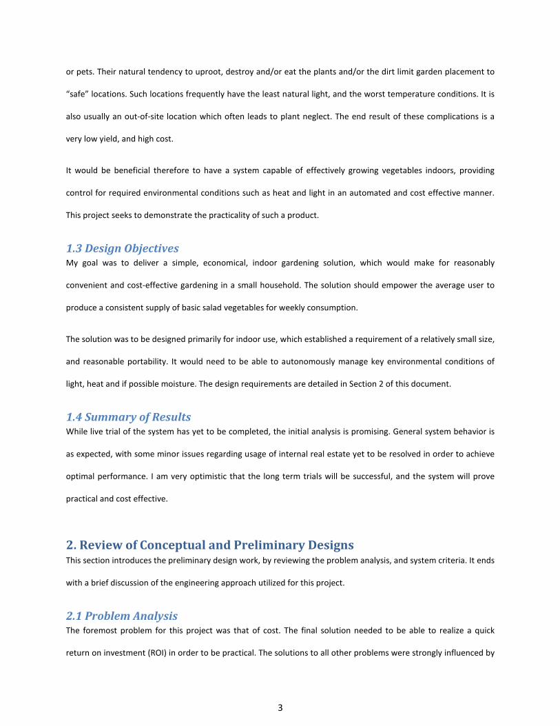
It is easiest to install the wiring as the frame is being installed. As such, the wire routing is shown in this section, in
Figure 10 below.
17
Figure 10. Frame wiring diagram
The wire types are specified in the following table.
Table 3. Wiring Specifications
Wire Name Conductor count Gauge, Type
Light Sensor 2 24 AWG, strand (Inexpensive speaker wire)
Temp. Sensor 2-3 18 AWG solid. Solid
Moisture Sensor 2 24 AWG, strand (Inexpensive speaker wire)
Light, Heat, Moisture (power) 2 18 AWG, strand, power cord
18
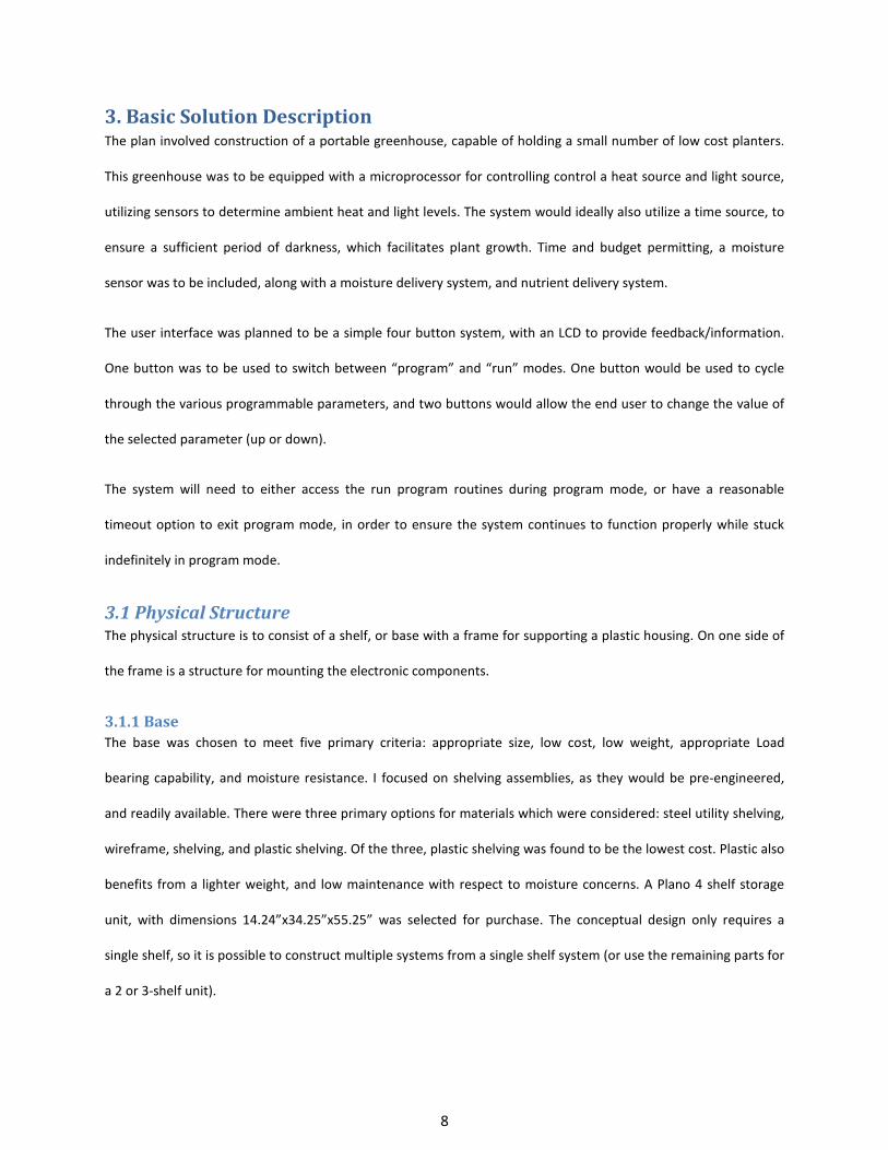
Figure 11. The assembled frame, installed on the base
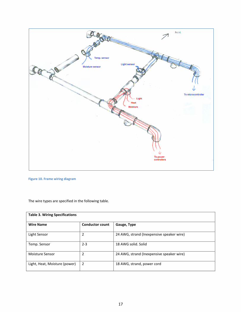
4.1.3 Housing The plastic housing was constructed from a single 9’ x 12’ sheet of 2 mil painter’s plastic, cut into two pieces as
shown in the image below (Figure 12). The shaded portions represent unused plastic.
Figure 12. Template for cutting the housing

19
The piece with the hole cut for the light sensor is placed on first. The hole should just fit over the TEE which is
pointing upward (which houses the light sensor). The flap labeled “A” should fold down against the side, the edges
wrapping slightly around the main posts. The flap labeled “B” is then folded over so that it covers “A”. Two dots of
Velcro are used to affix it to “A”. The “C” flap is then folded back over “A” and “B” and its edges are affixed to the
fold of “B” using two more pieces of Velcro. The second Sheet of plastic is place in similar fashion over the
opposite side of the frame. The finished structure with the housing in place can be seen in figures 13 and 14 below.
Figure 13. miniGreen with housing installed Figure 14. Housing pulled back to reveal interior
4.1.4 Electronics Mount The electronics mount is a Plywood board, ½” thick and 14” wide by 16” high. On the back, two “J”-hooks are
attached, one on each side, ¾” from the edge and 5” down from the top. These hooks Support the mount, by
dropping into the shelf posts. On the front of the board is the project box which houses the controller, and proto-
board. The remaining space on the board allows mounting of the power controllers.
Once the board was in place on the structure, I fastened a circular outlet box with a light socket, through the
plastic and into the plywood. The drawback to this approach is that the system is no longer easy to remove. It
seemed a good location for the heat element however, and frequent disassembly of the structure seems unlikely.
The board can be seen in Figure 15 below.

20
Figure 15. Electronics mount: Front view showing installed electronics (left) and partial rear view, showing J-hook installation to frame (right)
4.2 Electronic Systems This section documents the design of the various electronic systems.
4.2.1 Microcontroller I quickly gravitated to the Arduino Duemilanove as my processor of choice. The Arduino Duemilanove is an
ATMEGA base solution. The specific one I selected uses an ATMEGA328, with 14 digital I/O pins, 6 analog inputs,
32 KB flash memory and a 1KB EEPROM. The Arduino is an open source solution, which is appealing as it means the
solution is reproducible (and is reproduced) by a number of suppliers. It is reasonably priced and requires no
special hardware to program it (It is programed from a standard PC, via a USB cable, and freely available, open
source software package.

21
Figure 16. The Arduino microcontroller
4.2.2 Light Sensor The light sensor solution selection process was ultimately driven by cost. The selected device, the GL5528 is a
simple photo resistor, which converts intensity of 520 nm (green) light to a resistance. The obvious concern with
this choice is the fact that it is sensitive to the light range I am least interested in, as plants primarily require red
and blue light for photosynthesis. Unfortunately, the lowest cost, available device I could find, capable of sensing
for selected spectra, was $25. I considered constructing a custom sensor, using a red and blue LED’s in reverse to
obtain a measurement of the red and blue spectra. However, available time did not permit this for the current
project.
In considering the need for sensing light intensity, to ensure sufficient sunlight is available for photosynthesis, the
concern with respect to green spectrum sensing is the possibility of the household lighting creating a false positive,
where the system sees sufficiently intense light from an incandescent or a fluorescent source, which are lacking in
sufficient blue or red light respectively. This led to a careful examination of these thresholds. The minimum light
intensity required for plant growth of lettuce is 500-1000 LUX. Ideally, lettuce requires 10,000 lux or higher. The

22
table of typical illumination levels below shows most home lighting to be less the 500 LUX. Thus the risk of ambient
home lighting triggering a false positive is quite low.
Table 4. Common light levels for various room types
By constructing the sensor to allow a selective threshold choice from 500 to 2000 LUX, the user would be able to
adjust the threshold to ensure no false positives. Given this, the GL5528 was determined to be an acceptable
solution. The design then involved selecting an appropriate resistor to provide a reasonable scale of readings.
Figure 17 below shows the circuit design. Given the GL528 Power dissipation spec of 100 mW, I concluded that R
should be greater than 250 Ω. The circuit was constructed and tested with R values of 1K, 2K and 5K. Testing
involved using a LUX meter, placed next to the sensor, and constructing a table of input values as reported by the
Arduino for selected light intensity levels, generated by moving an incandescent bulb increasingly closer to the
sensor. Ultimately I determined that the 2K configuration, which provided a practical range of 0-2400 LUX, was a
good fit for this project.

23
Figure 17. Wiring diagram for light sensor
The sensor was mounted on top of the upward facing Tee in the left-side crossbar, connected to the appropriate
wires, and then covered with a plastic cap from an empty bottle of spray scent, which was sealed in place using
silicone sealant. The resistor was mounted on the proto-board, contained in the project box, next to the
Microcontroller, and the wires were attached appropriately.
4.2.3 Temperature Sensor I selected the LM335 temperature sensor for this project. The LM335 was a sensor I had some previous familiarity
with. It was one of the lower cost options available, and is packaged in a way that makes it relatively easy to heat-
shrink the electronics, providing moisture protection, without unduly impairing its temperature sensitivity. I
already had available to me an LM335A, which is right at the threshold of my desired resolution. Also available, for
the same price, is the LM335Z, which has a +/- .5° error. Both are identical in function and construction, and are
thus easily interchangeable. I therefore constructed the circuit using the LM335A. But ordered an LM335Z,
planning to replace it. Unfortunately I did not receive the LM335Z in time to prep it for installation.
The LM335 circuit was constructed per the Datasheet suggested configuration for a Basic Temperature Sensor
(Figure 18). R1 was determined to be approx. 2KΩ for my application. This was determined based on the
operational characteristics of the data sheet, given the V+ would be 5 V (Arduino supply voltage), which

24
established Voutput at room temperature (25° C) to be approximately 2V. Thus to Bias the circuit at a 1 mA current
(per the data sheet), I chose R to be 𝑉𝐼
= 2.001
= 2𝑘Ω.
Figure 18. LM335 circuit
4.2.4 Moisture Sensor The moisture sensor was a particularly challenging system. It was very difficult to find a solution which was
economically feasible for this project. Most effective systems cost hundreds of dollars. The lowest priced solution I
found readily available was over $20. Thus I opted ultimately to utilize a simple soil moisture meter. Opening the
meter, I discovered two leads, which I was able to connect wires to. I modified the Case to support connectors, as
shown in figure 19. Connecting these to a Voltmeter, and inserting the probe into a wet soil sample at varying
depths, I was able to obtain readings, recorded in table 5 below.
Figure 19. Front of soil moisture tester (left) and back, with cover removed to show modification to create an interface for connection to the Arduino (right).

25
Table 5. Voltage induced by the soil moisture meter at various meter levels
Meter 1 1.5 2 2.5 3 3.5 4
V (mV) 40 60 80 100 120 148 192
The full scale reading of the device was established to be approximately 200mV. Based on the observed readings,
the device was not linear (see figure 20). This was not a concern however, as the nonlinearity was not significant,
and we would be only be attempting to establish a very rough observation as to the dryness or wetness of the soil.
A low threshold would be established to activate the irrigation system, and a high threshold would be established
to deactivate it. To allow for variances in soil types, these thresholds would be user adjustable about the
determined default points.
Figure 20. Graph of soil moisture tester output
Given the small signal, it was necessary to amplify the signal for practical use with the Arduino, whose analog
inputs were designed to read values over a range of 0-5 volts. For my design I opted to use the LM324N, a Quad
OP-Amp package, which could be supplied directly from the Arduino’s 5 V output. By utilizing 2 of the OP-Amps in
0
50
100
150
200
250
1 1.5 2 1.5 3 3.5 4
Obs
erve
r Vol
tage
(mV)
Observed meter reading
V (mV)

26
the package, I created a two stage amplifier with a gain of approximately 21 V/V. The circuit design is shown in
figure 21 below.
Figure 21. Moisture sensor schematic
For the irrigation system I opted to use a solenoid valve, a gravity fed reservoir system, and drip irrigation. From
the remnant of the 20’ pipe used for the frame, I cut a 13.5” piece as the down pipe. On one end of this I attached
a ¾” thread (female) to slip adapter, using PVC glue. On the other end, I attached a ¾” thread (male) to slip, elbow,
using PVC glue. (See assembly in Figure 22, Top-Left). The threaded elbow was then connected to the solenoid
valve input, and a drip irrigation adapter was attached to the opposite end of the valve (Figure 22, Top-Right). This
assembly was then attached to the back, right frame post, using pipe clamps (zip ties would be more cost effective,
and preferable due to moisture, however for the prototype I opted for clamps to allow the system to be removed
and re-inserted as needed(Figure 22, Bottom-Left and Bottom-Right).

27
Figure 22. Irrigation system construction and installation.

28
For the reservoir, a 2 liter soda bottle was attached to a ¾” thread (male) to slip adapter. It was necessary to
slightly file the thread of the soda bottle, in order to successfully fit it into to the slip adapter. The two were sealed
together using a small amount of silicone adhesive (See Figure 23).
Figure 23. Soda bottle with PVC thread assembly
The bottom of the bottle was then cut off, to allow water to be added to the reservoir. This assembly was then
screwed into the Slip adapter protruding from the Plastic Shroud. Figure 24 Illustrates this.
Figure 24. Soda bottle reservoir attached to frame

29
4.2.5 Power Controller Switches Each of the three sensing and control systems requires a power controller, allowing a 5 V digital signal from the
Arduino to activate an AC power device. For simplicity, I wanted to use the same controller for all the devices if
possible. The device with the largest power handling requirement is the 60 W Heat emitter, which is expected to
draw approximately 60 W/110 V= 0.55 A. I began initial system construction using the PowerSwitchTail for the
power controller. It was a nicely contained, prebuilt, mechanical-relay-based solution, with a 10 A load capacity. It
was very convenient to work with. However it was not practical for the final solution, given its $15 cost per unit.
After some research, I ultimately settled on the S101S06 solid state relay as my final solution for power control.
The S101S06 can support a 3 Amp output current, has a 3000 V isolation voltage between the input and output,
and required only 20 mA of current to turn on, allowing the Arduino output pins to drive the device directly. The
PowerSwitchTail input requires 40 ma, which is the Arduino’s maximum current capability, thus requiring the
addition of a current amplifier to reliably drive the device. Using the S101S06 then further reduces the complexity
of the circuit design.
The S101S06 were assembled inline to the power cords of the devices to be controlled (see figure 25 below for an
example). This was a very trivial design, and took very little time to implement.
Figure 25. S101S06V power controller implementation

30
4.2.6 User Interface The user interface was constructed directly onto the project box used to house the microcontroller. A square was
cut in the top of the lid to accommodate the LCD, and 3 holes were cut in the top to accommodate the Buttons.
The selected LCD device utilized a serial interface, with a single TX pin. This was attached to Pin 4 of the
microcontroller, and a software library was found which implemented a software based serial interface on a user
selected digital pin of the Arduino.
4.2.7 Option: Clock I initially considered a hardware based Real time clock, to be integrated with the microcontroller. The primary
reason for desiring this was for the built-in battery backup. Given the already tightly constrained budget, I
ultimately opted to implement this in software. A freely available library was found, which already handled the
typical clock functions. This saved me considerable time and cost, as I merely had to tie into this library.
Due to unforeseen time difficulties, implementation of the clock was delayed until much later in the project than
intended. The clock library is functional and capable of displaying time, and handling the day/night cycles. I did not
have time to implement calendar support. This is not necessary for the functioning of the system, as scoped, but is
desirable for the planned data logging option. As implemented, the user has the ability from the interface to set
the minutes and second for the clock. The user can set the start of the day and night cycles in hour increments.
And the system has separate Light levels (including off), and temperature levels for the day and night cycles.
4.2.8 Option: Data Logging I initially considered a hardware based data logging solution. The original design used an SD card, and wrote
logging information to a CSV file, which could then be easily transferred to a PC for analysis. Again, the need for a
tight budget prevailed. I ultimately opted to exploit the systems built-in serial interface capabilities. Due to time
constraints, this optional feature has not yet been completed. However I intend to design a transfer protocol,
allowing the data to be transferred via a serial interface to a computer, in a predictable format, which can be easily
parsed and imported into a spreadsheet or other analysis package. As this will be a purely software
implementation, it will introduce no additional cost.

31
5. Project Implementation The project implementation began with the construction of the frame, as described in section 4. In parallel with
that work I acquired the Arduino Duemilanove, and began familiarizing myself with it and its capabilities. I
constructed a fast prototype of the light sensor, and the temperature sensor, utilizing arbitrarily selected
thresholds, which when triggered, would light an LED. I then constructed the project box, and integrated it and the
sensors to the frame. With the light sensor in place on the frame, I configured a test program to read the sensor
and report the value.
Using this code, a lamp, and a Lux meter, I collected sensor readings, which were then used to create the table of
values used in the program code to determine threshold settings. Table 7 below lists the results of this analysis.
Table 6. Table of observed Arduino values and selected user values at various Lux levels Lux 500 600 700 800 900 1000 1200 1400 1600 1800 Arduino Value 447 412 383 364 356 320 291 265 248 236 User Value 1 2 3 4 5 6 7 8 9 10
With the Light and temperature sensors in place and operational, I installed the grow-light, and ceramic reptile
heater, initially connecting them to the PowerSwitchTail modules. I then installed the canopy, as detailed in
section 4. I now had a basic, functional system, per my minimum requirements. The light sensor was not
thoroughly tested in an ideal, live environment. It was necessarily in my basement, where there is never sufficient
sunlight to trigger the threshold at a practical level. However, forced tests demonstrated appropriate operation.
The temperature sensor and heater work quite effectively, maintaining the temperature within 2-3 degrees of the
set-point, as desired.
The system was connected to a Kill-a-Watt® power metering device, and based on present observations, power
consumption estimates from table 2 are quite accurate.
After installing the canopy, I began a live trial, using a soil composed of 50% topsoil, and 50% shredded paper. I
planted a mix of lettuce, radishes and carrots. While this was going, I began work on the moisture sensor, and
irrigation system. Unfortunately, a week after I began the live trial, a family emergency led to the system being

32
shut down for two weeks and the live trial was aborted. There is now insufficient time to complete a full trial prior
to the end of the project term. However I plan to continue live trials for the next year, in order to optimize the
design, and establish its practical viability.
6. Final Scope of Work Statement To date, the structure is completed, and the basic system is functional to the targeted minimum specification.
Additionally, the moisture and Irrigation subsystem is implemented, though not yet fully tested. The gravity fed
irrigation system seems to work reasonably well, however it is not ideal. The water output from the nozzles is not
equal, and proper elevation of each nozzle is necessary to ensure reliable flow. Also, the soda bottle reservoir is
really only large enough to accommodate a single watering. A larger reservoir is necessary to truly be practical. I
have recently identified a small water pump for roughly the same costs of the solenoid. I would like to investigate
the possible of using it instead. This would allow for a much larger, floor-based reservoir, and it would also
pressurize the irrigation lines, thus providing more even watering.
Once concern with the light and heat system as implemented: The heater is larger than I anticipated, and thus
extends further into the greenhouse space than expected. This prevents the light from being moved up and down
easily and safely. I don’t believe the light is intense enough to deliver sufficient energy to new seedlings from the
top of the frame. I have temporarily resolved this by making the heater placement moveable, using a clamp and
shield. This is not an acceptable long-term solution. One possible solution to this would be to construct a small
extension on the side of the frame, allowing the heater to be recessed. Another option would be to replace the
fluorescent grow light with and LED solution, made to fit the space.
I have implemented one of the three S101S06 power controllers, and a second one has been constructed. All three
are identical, so this is sufficient to demonstrate the practicality of the concept. The one possible exception to this
is the solenoid, which may require the addition of a snubber circuit to ensure that the Solid State Relay can shut off
reliably.
The software clock is in place, and has the necessary user interface to allow the user to set the time (hours, and
minutes, and the start hours for the day and night periods. The user can also independently set light threshold and
33
temperature threshold for the day and night periods. I still need to implement setting date information, to allow
effective logging, and the logging option still needs to be implemented.
Basic system functionality testing has been completed, and the system appears to operate as desired. It will be
necessary for live tests to be performed for the next several months to confirm that a). the system is capable of
support plant growth as desired and b). the system is capable of growing sufficient produce to offset the cost of
maintenance.
7. Other Issues The solution as detailed does not have a mechanism for cooling the interior. While this is a relatively unlikely
scenario, it is conceivable that a user might place the system in an area where overheating could become a
concern. It might be worthwhile to consider a small fan and venting system to accommodate this (though that
would add some cost, both in terms of materials and in power consumption).
As the clock and other usability enhancements are added, the user interface as designed is becoming a bit
cumbersome for practical use. I have considered this in an alternative design flow, see appendix A for treatment of
the alternate design.
While the SS101S06 Solid State Relay has been implemented and demonstrated to work for a power controller for
this project, I have not yet designed an appropriate mounting for it. This needs to be done to ensure the safety and
long-term reliability of the system.
It is not really necessary to check the moisture sensor as often as I do. If the last reading was a “wet” reading,
sampling could technically be done every 12-24 hours. If the last reading was a dry reading (and therefore the
irrigation switch was active), then more frequent checking is necessary. Given that, it might be possible to improve
power consumption by connecting the OP-Amp power pins to a digital output pin on the Arduino. And then
enabling that pin just before taking a reading, and then shutting it off when no longer needed. This isn’t likely to
generate an enormous cost benefit, but still may be worth considering.

34
8. Cost Estimation The hardware cost for this project is presented below, broken out by subsystem.
Table 7. Cost broken down by subassembly
Approximately 160 hours have been invested to date in research, design, construction and testing efforts.
Based on power consumption tests, operational costs for the system are estimated to be very close to the $63 approximation established in table 2 of this document.
35
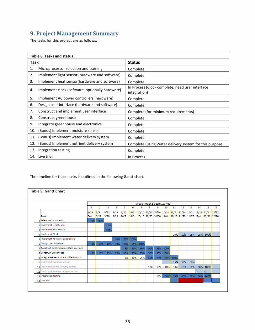
9. Project Management Summary The tasks for this project are as follows:
Table 8. Tasks and status Task Status 1. Microprocessor selection and training Complete 2. Implement light sensor (hardware and software) Complete 3. Implement heat sensor(hardware and software) Complete
4. Implement clock (software, optionally hardware) In Process (Clock complete, need user interface integration)
5. Implement AC power controllers (hardware) Complete 6. Design user interface (hardware and software) Complete 7. Construct and implement user interface Complete (for minimum requirements) 8. Construct greenhouse Complete 9. Integrate greenhouse and electronics Complete 10. (Bonus) Implement moisture sensor Complete 11. (Bonus) Implement water delivery system Complete 12. (Bonus) Implement nutrient delivery system Complete (using Water delivery system for this purpose) 13. Integration testing Complete 14. Live trial In Process
The timeline for these tasks is outlined in the following Gantt chart.
Table 9. Gantt Chart
36
10. Conclusion The primary purpose of the project was to determine the practicality of constructing an autonomous, indoor
greenhouse system, given rather tight economic parameters. From my efforts on this project, I have concluded
that it is difficult, but possible.
Constructing the whole system, as detailed in this project report - within the available funds to achieve a three
year return on investment - is doable, but only barely so, with very little margin for error or deviation. Operating
the system for a three year return would mean doing so without the use of fertilizers or other such consumables.
The three year target would be quite practical, if you opted to eliminate the irrigation system, making that a
manual process. The moisture sensor could be left in place, with its output tied to an indicator LED, thereby still
allowing for feedback to the user regarding the need for moisture.
Practically, however, given the complete implementation is outlined, a user should more realistically expect a 3.5 -
4 year time frame to recover the cost of constructing, allowing for. This is still an acceptable time frame, and
leaves this solution a viable one.
In a mass production scenario, material costs should drop considerably, allowing the device to target a three year
ROI, while allowing a modest margin for profit.
This project was a great experience. It was a great opportunity to apply my educational knowledge to a practical,
real-world scenario. While I was unable to complete everything I wished in the time available - primarily due to
unforeseen events – I am still quite satisfied with the current end-result, and I am looking forward to expanding
upon this work with the second revision.

37
References
1. Mittleider, J.R. More Food from Your Garden. Woodbridge Press Publishing Company, 1975
2. Boriss, Hayley and Henrich Brunke. Lettuce Profile. June 2010. 20 August 2010
<http://www.agmrc.org/commodities__products/vegetables/lettuce_profile.cfm>.
3. Derived by using Logan, Utah store prices. It is expected that these numbers will be conservative,
compared to National average prices.
4. U.S. Energy Information Administration. Average Retail Price of Electricity to Ultimate Customers by End-
Use Sector, by State. June 2010. 20 August 2010
<http://www.eia.doe.gov/electricity/epm/table5_6_b.html>.
5. Whiting, David CMG GardenNotes #143. August 2010.
<http://www.cmg.colostate.edu>.

38
Appendix A: An Alternative, Multi-menu User Interface Design
As more enhancements to the functionality of the miniGreen system are added, the linear operation of
the user interface as originally designed is likely to become too cumbersome for practical use. The image
below (Figure 26) shows the functional operation for an alternative menu system, which still uses the 3
button interface presently implemented.
Figure 26. Alternative multi-menu design