Embed Size (px)
Citation preview

Edinburgh Research Explorer
Mechanical Properties and Applications of Two-dimensionalMaterials
Citation for published version:Zhang, R & Cheung, R 2016, Mechanical Properties and Applications of Two-dimensional Materials. inIntech.
Link:Link to publication record in Edinburgh Research Explorer
Document Version:Peer reviewed version
Published In:Intech
General rightsCopyright for the publications made accessible via the Edinburgh Research Explorer is retained by the author(s)and / or other copyright owners and it is a condition of accessing these publications that users recognise andabide by the legal requirements associated with these rights.
Take down policyThe University of Edinburgh has made every reasonable effort to ensure that Edinburgh Research Explorercontent complies with UK legislation. If you believe that the public display of this file breaches copyright pleasecontact [email protected] providing details, and we will remove access to the work immediately andinvestigate your claim.
Download date: 21. Mar. 2020

1
Mechanical Properties and Applications
of Two-dimensional Materials
Rui Zhang and Rebecca Cheung*
Scottish Microelectronics Centre, The University of Edinburgh, King’s Buildings, Edinburgh
EH9 3FF, United Kingdom
Corresponding author email: [email protected]
Abstract: Two-dimensional (2D) materials have attracted increasing attention recently due
to their extraordinarily different material properties compared to conventional bulk
materials. 2D materials possess ultralow weight, high Young’s modulus, high strength,
outstanding carrier mobility, as well as high anisotropy between the in-plane and out-of-
plane mechanical properties. The nearby atoms in the same plane of layered 2D materials
are connected via covalent bonding while the interlayers are stacked together via weak van
der Waals interactions. In this article, we review the in-plane mechanical properties
(including the in-plane Young’s modulus, pretension, breaking strength/strain) and out-of-
plane mechanical properties (including the perpendicular-to-plane Young’s modulus, shear
force constant and shear strength) of different 2D materials, varying from conductors,
semiconductors to insulators. The different fabrication methods for suspended 2D material
structures are presented. The experimental methods and principles for mechanical
properties characterization are reviewed. A comparison of the mechanical properties
amongst different 2D materials is summarized. Furthermore, electrical output change as a
result of mechanical deformation (piezoresistive and piezoelectric effects) are introduced
briefly. By exploiting the unique mechanical and mechano-electric transduction properties,
2D materials can be used in wide ranging applications including flexible electronics, strain
sensors, nanogenerators and innovative nanoelectromechanical systems (NEMS).
Keywords: 2D materials, Mechanical properties, Suspended structure, Strain sensors,
Nanoelectromechanical Systems (NEMS)
In-doc controls

2
1. Introduction
Since the first successful preparation of graphene by mechanical exfoliation from graphite
crystals in 2004 [1], two-dimensional (2D) materials have attracted dramatic attention due to
their extraordinary physical properties (ultralow weight, high Young’s modulus and high
strength) [2-7] and outstanding electrical properties [1] compared with conventional bulk
materials. In the past few years, graphene, with the highest measured Young’s modulus
(~ 1 TPa) [3], is the most widely studied 2D material. Studies have shown that graphene
filled into the polymer matrixes can reinforce the mechanical properties of the composites
significantly [8]. However, pristine graphene does not have a bandgap [9], which limits its
applications in certain fields requiring a semiconducting material. As a potential substitute
material of graphene, the transition metal dichalcogenides (TMDCs, e.g. MoS2 and WSe2)
and black phosphorus (BP) with an intrinsic bandgap [10, 11] possess the potential for
electronics and optoelectronics applications [12-15] and open a new field for 2D materials
study. Moreover, the existence of piezoelectricity and the more sensitive piezoresistive effect
in TMDCs compared to graphene under mechanical deformation make them more
interesting for innovative applications including tactile strain sensors [16], nanogenerators
[17] and advanced nanoelectromechanical systems (NEMS).
In this review, firstly, we introduce the common approaches used for fabricating suspended
2D materials structures. Then, characterization methods for extracting the in-plane and out-
of-plane mechanical properties of 2D materials are presented. A summary of the
experimental results is given. In the last section, we introduce the electrical output change of
2D materials induced by mechanical deformation - piezoresistive and piezoelectric effects.
In addition, we provide some example applications of 2D materials that make use of their
extraordinary mechanical as well as mechano-electric transduction properties.
2. Fabrication of suspended 2D materials
Generally, in order to measure the mechanical properties of 2D materials experimentally, a
suspended structure needs to be fabricated. There are mainly two ways of fabricating a
structure suspended with 2D materials. One approach is to transfer the 2D materials directly
onto the pre-patterned substrates [3, 7, 18-23]. The other approach is to transfer the 2D
materials on the substrate first and then remove the sacrificial layer beneath the transferred
2D materials [24-31]. Figure 1(a, b) show the two schematics of the first fabrication approach
while Figure 1(c) shows the second approach.
In the first approach, taking SiO2/Si substrate for example, holes or cavities are patterned in
the SiO2 layer with lithography and wet/dry etching techniques, as shown in the first step of
Figure 1(a). Then, 2D materials are transferred onto the pre-patterned SiO2/Si substrate by
the exfoliation method, forming suspended 2D materials structure (second step of Figure
1(a)). With this method, the suspended structure can be fabricated theoretically on various
kinds of substrates. However, with the conventional mechanical exfoliation method, since

3
the 2D material sheets distribute randomly onto the substrates, the 2D material sheets may
not cover necessarily the specific hole in the SiO2 layers, bringing the challenge of improving
the production rate. Normally, two methods can be employed to address this problem. One
method is to fabricate repeatable patterns (e.g. hole arrays) in the substrate [3, 7, 22] to
enhance the probability of producing the suspended structures, as shown in Figure 2(a).
Another method is to employ a modified exfoliation method (transfer printing/stamping [20,
32]) with a transparent viscoelastic material as the carrier for the 2D materials which enables
a precise transfer of 2D materials to the desirable location [19, 21].
In most cases, electrical signal needs to be applied to the suspended 2D materials, therefore,
metal contacts need to be made to contact the suspended 2D materials, as shown in the third
step of Figure 1(a). In order to avoid the common wet process inducing the collapse of 2D
membranes, the shadow mask method [27] instead of lithography should be used. In
addition, by combining conventional lithography, lift-off of deposited metal and transfer
printing/stamping of 2D materials, one can realise the fabrication of suspended 2D materials
supported on patterned metal contacts, as depicted in Figure 1(b) and Figure 2(b).
The schematic of the second approach of fabricating a suspended 2D material structure is
presented in Figure 1(c). After the transfer of 2D material onto substrate and metal contacts
deposition, the 2D material is suspended by etching the underlying sacrificial layer with the
pre-deposited metal contacts acting as the etching mask and clamping of the 2D materials.
In this method, SiO2 has been used widely as the sacrificial layer, which is removed
commonly by anisotropic wet etching with buffered hydrofluoric acid (BOE). In order to
prevent the 2D materials from collapsing due to the surface tension between the 2D
materials and BOE, the drying process is operated normally in a critical point drier (CPD)
[25, 29, 30]. In addition, the etching time needs to be adjusted carefully to control the
undercut of SiO2 beneath the metal contacts. Although a more complex structure can be
fabricated with this approach, shown in Figure 2(b), the wet etching involved in the
fabrication process may introduce some contamination in the 2D materials, which may
degrade the performance of the devices. Moreover, the acids used in this process are not
suitable for some 2D materials, such as Bi2Se3 [33] and metals (e.g. Ti, Al). Thus, in order to
avoid acid etching in the fabrication process, photoresist can be used as the sacrificial layer
instead of SiO2, which can be removed with photoresist developers [33, 34].

4
Figure 1. Schematic of two representative approaches of suspended structures fabrication:
(a, b) Transfer the 2D materials directly onto the pre-patterned substrates; (c) Suspend the
2D materials by etching the sacrificial layer underneath.
Figure 2. (a) Optical image of graphene suspended over hole arrays [35]. (b) SEM images of
a MoS2 bridge supported on Au electrodes [23]. (c) SEM image of suspended graphene
stripe under Au electrodes [25].
3. Mechanical properties
As mentioned before, 2D materials possess high anisotropy between the in-plane and out-
of-plane mechanical properties. In pristine layered 2D materials, the nearby atoms in the
same plane are bonded covalently with low defects density resulting in strong in-plane
mechanical properties. While the interlayers are stacked together via weak van der Waals
interactions, allowing layers to slide easily when shear stress is applied, the effect of which
can give rise to lubrication properties. In this section, the experimental methods used to
characterize the mechanical properties of 2D materials are introduced and the
corresponding empirical results are summarized.
3.1. In-plane properties

5
The in-plane mechanical properties (including the in-plane Young’s modulus, pretension,
and breaking strength/strain) of 2D materials have been studied extensively in bending
experiments on suspended 2D sheets. In the bending experiments, atomic force microscope
(AFM) is used widely to characterize the deformation of the suspended sheets under a
certain amount of force. The force applied during the experiments can be divided into two
categories: concentrated force and distributed force. In the following subsections, all the
mechanical properties mentioned indicate the in-plane properties, unless stated otherwise.
3.1.1. Applying concentrated force
The indentation experiment conducted under AFM is one of the most popular methods for
measuring the mechanical properties of 2D materials. In most cases, an AFM probe indents
towards the centre of circular suspended 2D materials, as shown in Figure 3(a). During the
indentation, the displacement of piezoelectric scanner Z (when the AFM probe starts to
contact with the membrane) and the deflection of AFM probe d are recorded. The
indentation depth at the centre of a membrane can be determined by Z d and the
force applied from the AFM tip onto the membrane can be derived from F k d , where k
is the spring constant of the AFM probe, which can be calibrated via a reference cantilever
[36] or calculated using the Sader method [37, 38]. Then, the force F versus deformation
curves of a suspended 2D material can be extracted, as shown in Figure 3(b). When the
radius of the AFM tip tipr is far smaller than that of the hole r and the bending stiffness of
the measured 2D material is negligible (monolayer or few-layer), the F - curves can be
approximated using the Schwering-type solution as Eq. (1) [3, 39, 40] :
3
2 2 30 2
D D qF Er
, (1)
where 2
0
D is the pretension, 2DE is the 2D elastic modulus, is the Poisson’s ratio and
q is a dimensionless constant determined by 21/ (1.05 0.15 0.16 )q . By fitting the
experimental curves with Eq. (1), the pretension 2
0
D and 2D elastic modulus 2DE of the
membranes can be derived. Due to the increasing thickness of 2D material (> 15 nm) [41], the
mechanical behaviour of 2D materials undergoes a membrane to plate regime transition and
therefore, the bending stiffness should be taken into consideration by adding another term
into Eq. (1) thus forming a modified model [6] which gives a better estimation of the
pretension 2
0
D :
22
2
32 2 30 2
4
3(1- )
DD DE t
r
qF E
r
, (2)
where t is the thickness of the measured 2D material.

6
Figure 3. (a) Side view schematic of the indentation experiment on a suspended 2D
membrane. (b) Representative force-deformation curves for multilayer WSe2. The fitted
curves using the Schwering-type solution agree well with the experimental results. [42]
During an indentation experiment with a spherical indenter, the maximum stress for a
circular and linear elastic membrane as a function of the applied force F can be derived
with the expression as [43] :
2
2
max
tip4
DD FE
r
, (3)
where 2
max
D is the maximum stress at the centre of the film (under the AFM tip). Thus, the
breaking stress of the 2D material can be estimated by acquiring the force which breaks the
2D material during the indentation. Assuming the stress of the 2D material has a linear
relationship with its strain, the breaking strain can be predicted by 2 2
max max /D DE .
Apart from the circular membrane, the indentation experiment can be operated also at the
centre of a beam structured 2D material with two ends fixed [4, 44, 45]. In this case, the
relation between applied force F and deformation at the centre of the 2D material can be
modelled with the expression [46] :
2 2 2
2
03 3
316 8
3
D DDE wt wE
l lF , (4)
where l and w are the length and width of the suspended beam, respectively.
It is worth noting that it is extremely important to identify the zero displacement/force point
precisely for nanoindentation experiment [47]. An inaccuracy of 2-5 nm in determining this
point may lead to a 10% error in the extracted 2DE [35]. In order to compare the elastic
properties of a particular 2D material with its bulk counterpart as well as other 2D materials,

7
the 2D elastic modulus 2DE sometimes needs to be converted to the normal 3D Young’s
modulus YE by dividing the 2D value by the thickness of the 2D material t .
From the models of Eq. (1, 2, 4), we can see that the applied load has an approximate linear
relationship with the indentation depth when the membrane deformation is small, and
significantly follows a cubic relationship under large deformation. Thus, in the linear regime
(small deformation of membrane), the effective spring constant of circular and beam
structured membrane can be extracted as:
32
02 2
32
03
4
3(1- )
16
D
circular Y
D
beam Y
tk E
r
wtk E
l
. (5)
By measuring the effective spring constant of the same kind of 2D material with different
design, thickness t or dimensions ( r , w or l ), the Young’s modulus YE and pretension 2
0
D can be extracted. Note that this method is only valid under the assumption that YE
and 2
0
D are independent on thickness or dimension of the 2D material, assumptions of
which are under debate at present [48, 49].
3.1.2. Applying distributed force
Apart from concentrated force applied with an indenter, distributed force (such as
electrostatic force [50] or pressure force [51]) can be applied on suspended 2D material to
measure the mechanical properties. In order to produce an electrostatic force, metal contacts
need to be made on/below 2D membrane so that a voltage can be applied between the
membrane and the back gate electrode, as shown in Figure 4(a, b). Moreover, by creating a
pressure difference between the inside of micro-cavities covered by the 2D membrane intp
and the outside atmosphere extp , a pressure force p can be produced, as depicted in Figure
4(c, d). The deformation of a membrane under distributed force can be characterized directly
via tapping mode AFM (Figure 4(e)). In addition, by measuring the Raman shift of 2D
material under loading and without loading, the local strain of 2D material can be extracted
indirectly [49]. After building a specific mechanical model which describes the relationship
of the deformation of the membrane due to the voltage bias [50] or pressure difference [51,
52], the mechanical properties can be extracted by fitting experimental results with the
appropriate model.

8
Figure 4. (a) Top view optical image of a graphene suspended over hole arrays. (b)
Schematic of producing electrostatic force by applying a voltage VS across the back gate and
the graphene. [50] (c) Schematic of a graphene sealed microchamber. Inset: optical image of
a graphene membrane over a hole. (d) Side view schematic of the graphene sealed
microchamber. (e) Tapping mode AFM image of a graphene membrane with p > 0. [52]
3.1.3. Results summary
Table 1 summarizes the mechanical properties of 2D material families ranging from
conductor (graphene), semiconductor (semiconducting TMDCs and BP) to dielectrics
(graphene oxide (GO), mica and h-BN). Overall, the Young’s modulus of 2D materials is
larger than that of corresponding bulk materials, due to the lower crystal defects and
interlayer stacking faults in 2D materials [6].
3.1.3.1. Young’s modulus
Pristine monolayer graphene (prepared by mechanical exfoliation from bulk graphite) is
reported to be the stiffest 2D material on earth so far with a Young’s modulus of ~ 1 TPa [3,
49, 51], because of the strong in-plane covalent carbon-carbon bonds. For 2D TMDCs - MX2
(M=Mo, W; X=S, Se) with the same crystal structure (chalcogen atoms in two hexagonal
planes separated by a plane of transition metal atoms) [11], a smaller Young’s modulus of
WSe2 has been observed compared with MoS2 and WS2 [42]; due to a decrease in the charge
transfer and an increase in the lattice constant, resulting in a weakened binding between the
metal and chalcogen [53], as M changes from Mo to W and X changes from S to Se.
Meanwhile, the Young’s modulus of some 2D materials (e.g. MoS2, BP and h-BN) [2, 7, 41,
48] have been found to decrease with an increase in their thickness (number of layers),
which is caused mainly by interlayer stacking errors. The occurrence of interlayer sliding in
multilayer 2D materials during indentation is also a factor for underestimating the intrinsic
9
Young’s modulus [7]. However, the Young’s modulus of WSe2 remains unchanged
statistically with increasing number of layers, which possibly results from the strong
interlayer interaction in WSe2 [42]. As stated before, for 2D materials with thickness
dependent Young’s modulus, precaution needs to be taken when using model Eq. (5) to
derive the Young’s modulus. Furthermore, the highly anisotropic atomic structure in 2D
materials, such as BP, presents an anisotropic Young's modulus along the different crystal
orientations [54].
In addition, the mechanical properties of 2D materials largely depends on the density of
crystal defects and thus is related to the preparation methods. For instance, the larger
number of vacancy defects in the GO reduced graphene and the existence of voids at the
grain boundaries, together with wrinkles in polycrystalline graphene prepared by the CVD
method, can contribute to the weaker mechanical properties [4, 55]. In addition, the presence
of a larger number of grain boundaries can affect the Young’s modulus of 2D materials
negatively [56]. By optimizing the processing steps of suspended 2D materials fabrication,
the quantity of crystal defects and wrinkles in 2D materials can be reduced thus leading to
an improvement of the mechanical properties [56]. Research has shown that the elastic
properties can be recovered by flattening the wrinkles in CVD graphene with a small pre-
stretch [47]. The mechanical properties of 2D materials can be improved also by introducing
controlled density of defects, such as Ar+ plasma irradiation [35].
3.1.3.2. Pretension
The factors that can affect the pretension in 2D materials are quite complicated. The
pretension not only depends on the intrinsic mechanical properties of 2D materials, but also
on the fabrication process of the suspended structure (e.g. the method of transferring 2D
material onto the substrates). Therefore, the pretension values of suspended 2D materials in
Table 1 vary greatly. Generally, the dry transfer process with scotch tape or viscoelastic
stamp introduces higher pretension compared with wet transfer process such as solution-
based deposition [57]. Suspended structures fabricated by etching sacrificial layer (method
shown in Figure 1(c)) normally possess less pretension than 2D materials transferred
directly onto pre-patterned substrates (method shown in Figure 1(a, b)). Annealing, as a
common method to remove the residue on 2D materials left over by a fabrication process,
can introduce thermal stress due to the different thermal expansion coefficients between the
substrates and the 2D materials.
3.1.3.3. Breaking strength
As presented in Table 1, the 2D materials with higher Young’s modulus normally possess
higher breaking strength. Many reports have found that the breaking stress of 2D materials
can reach the theoretical upper limit ( YE /9) [7], due to low disorder and impurities in the
characterized 2D materials. The existence of anisotropic breaking strength along armchair
and zigzag directions has been found in BP, possibly resulting from its anisotropic Young’s
modulus [54]. Except for the 2D dielectrics (mica and h-BN), the breaking strain of most 2D
materials is above 7%, which is comparable with the common materials used as substrates

10
for flexible electronics, namely polyimide (PI) or (Polydimethylsiloxane) PDMS [58],
implying that most of the 2D materials are compatible with flexible electronic devices.
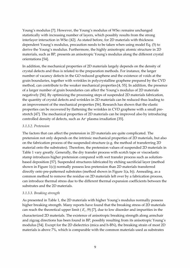
Table 1 Summary of the in-plane mechanical properties of 2D materials measured from
experiments.
Material Number
of layers
Young’s
modulus (GPa)
Pretension
(mN/m)
Breaking
stress (GPa)
Breaking
strain (%)
Characterization
Method
Ref.
Graphene
(Mechanical
exfoliated )
1 1000 ± 100 70 - 740 130 ± 10 ~12 Indentation on
circular membrane
[3]
23-43 ~1000 N/A N/A N/A Electrostatic force [50]
4 930 ± 48 N/A N/A N/A Pressurizing
membranes
[52]
1-5 1000 ± 31 N/A N/A N/A Pressurizing
membranes
[51]
1, 2 2400 ± 400 (1L)
2000 ± 500 (2L)
N/A N/A N/A Pressurizing
membranes
[49]
3-14 ~800 N/A N/A N/A Indentation on
beam
[46]
Graphene
(Mechanical
exfoliated +
Ar plasma
irradiation)
1 ~1550 200 - 800 80 - 94 N/A Indentation on
circular membrane
[35]
Graphene
(GO
reduced)
1 250 ± 150 N/A N/A N/A Spring constant of
beam
[4]
Graphene
(CVD
growth)
1 ~157 ~85 ∼35 N/A Indentation on
circular membrane
[55]
1 ~1000 N/A ∼121 (small
grains)
∼140 (large
grains)
N/A Indentation on
circular membrane
[56]
1 ~800 ~100 ∼55 N/A Indentation on
circular membrane
[47]
1, 2 270 ± 100 (1L)
200 ± 60 (2L)
20 - 100
22 ± 4 (1L)
21 ± 6 (2L)
6-11 Indentation on
circular membrane
[7]
11
MoS2
(Mechanical
exfoliated)
5-25 300 ± 10 0.15 ± 0.15 N/A N/A Spring constant of
circular membrane
[59]
5-25 330 ± 70 50 ± 20 N/A N/A Indentation on
circular membrane
[6]
MoS2 (CVD
growth)
1, 2 260 ± 18 (1L)
231 ± 10 (2L)
110 ± 40 (1L) N/A N/A Indentation on
circular membrane
[48]
WS2 (CVD
growth)
1 272 ± 18 150 ± 30 N/A N/A Indentation on
circular membrane
[48]
WSe2
(Mechanical
exfoliated)
5, 6, 12, 14 170 ± 7 (5L)
166 ± 6 (6L)
168 ± 7 (12L)
165 ± 6 (14L)
638 ± 22 (5L)
691 ± 37 (6L)
499 ± 34
(12L)
137 ± 26
(14L)
>12 >7.3 Indentation on
circular membrane
[42]
BP
(Mechanical
exfoliated)
17-35 27 ± 4
(armchair
direction)
59 ± 12 (zigzag
direction)
N/A 2.2
(armchair
direction)
4.2 (zigzag
direction)
7.2
(armchair
direction)
6.5 (zigzag
direction)
Spring constant of
beam
[54]
17, 37 276 ± 32 (17L)
90 ± 6.4 (37L)
180-1200 >25 >8 Indentation on
circular membrane
[41]
GO
(Solution
based
deposition)
1-3 208 ± 23 (1L)
224 ± 18 (2L)
230 ± 27 (3L)
54 ± 14 (1L)
32 ± 6 (2L)
28 ± 4 (3L)
N/A N/A Indentation on
circular membrane
[57]
Mica
(Mechanical
exfoliated)
2-14 202 ± 22 140 ± 80 4-9 2-4.5 Indentation on
circular membrane
[60]
h-BN (CVD
growth)
2, 4, 5 279 ± 20 (2L)
269 ± 13 (4L)
252 ± 15 (5L)
8.8 ± 1.2 (2L)
12.8 ± 1.3
(4L)
15.7 ± 1.5
(5L)
~9 2.2 Indentation on
circular membrane
[2]
3.2. Out-of-plane properties
The research on the out-of-plane mechanical properties of 2D materials includes
characterizing the elasticity perpendicular to the plane’s direction and the interlayer shear
force constant/strength parallel to plane’s direction. Unlike the experiments already
12
conducted in characterizing the in-plane mechanical properties of 2D materials,
experimental investigations on quantifying the out-of-plane properties are still quite scarce,
mainly because of the technical difficulties in characterization [61]. Overall, out-of-plane
properties can be explored directly by applying normal/shear force to 2D materials or
indirectly via Raman spectroscopy. This section introduces the various experiments
conducted thus far related to out-of-plane properties measurement.
3.2.1. Direct characterization
3.2.1.1. Perpendicular-to-plane elasticity
Direct investigation of the perpendicular-to-plane elasticity of few-layer 2D materials
remains challenging, because extremely small indentations need to be conducted on
supported 2D sheets. Since the interlayer distance of 2D materials is so small (< 1 nm), the
maximum indentation depth should be only a few angstroms (smaller than the interlayer
distance) [62].
An unconventional AFM-based method (modulated nanoindentation as shown in Figure
5(a)) with a high indentation depth resolution of 0.1 Å [63, 64] has been employed to
measure the perpendicular-to-plane elasticity of highly oriented pyrolytic graphite (HOPG),
epitaxial graphene (EG), epitaxial graphene oxide (EGO) and conventional GO successfully
[62]. During the indentation, the AFM tip oscillates at 1 kHz frequency with an amplitude of
~ 0.1 Å (piezoZ ) controlled by a piezoelectric tube. The AFM feedback loop sets a normal
force ZF applied on the 2D materials from the AFM tip by setting the position of the
piezoelectric tube vertically. A tip oscillation with an amplitude of piezoZ results in a
variation of the normal force ZF monitored via the deflection of a cantilever. At a certain
normal force ZF , the tip-2D material contact stiffness contactk can be obtained via the
expression below:
1
1 1Z
piezo lever contact Z
F
Z k k F
, (6)
where leverk is the spring constant of the AFM cantilever. Then, the force ZF versus
indentation depth indentZ curves (as shown in Figure 5(b)) can be derived by integrating
Z contact Z indentdF k F dZ as:
0
ZF Zindent
contact Z
dFZ
k F . (7)
When the indentation depth is in the sub-nanometre regime, the perpendicular Young’s
modulus can be extracted by fitting the ZF - indentZ curves with the Hertz model (as shown in
Figure 5(c)):

13
* 1/2 2/34
3indentF E r Z , (8)
where 2 2* 1 / 1 /sample sample tip tip
Y YE E E , with sample , tip , sample
YE and tip
YE being the
Poisson’s ratio and Young’s modulus of the measured 2D material and AFM tip,
respectively. With this approach, the perpendicular Young’s modulus of HOPG, EG, EGO,
conventional GO, is measured to be 33 ± 3, 36 ± 3, 23 ± 4, and 35 ± 10 GPa, respectively,
which is far smaller than the in-plane Young’s modulus. In addition, the intercalated water
between GO layers can affect the perpendicular Young’s modulus significantly. This method
is very sensitive to the 2D material/substrate interaction and the number of layers of 2D
material and thus is useful for investigating the 2D material/substrate interaction [62].
Figure 5. (a) Schematic of modulated nanoindentation on 2D materials. (b) Force-indentation
curves for SiC, 10-layer EG, and 10-layer EGO extracted from the nanoindentation. (c) Force-
indentation curve for HOPG and the Hertzian fitting. Adapted from [62].
3.2.1.2. Shear force constant/strength
To measure the interlayer shear force constant/strength, proper shear stress should be
applied to the interlayer interface of a 2D material using a probe. Gao et. al. [61] have
measured the interlayer shear strength of MoS2 with a shearing strength test under in-situ
transmission electron microscopy (TEM) characterization, as shown in Figure 6. During the
test, a multilayer MoS2 flake sandwiched between a 3.5 μm thick focussed ion beam (FIB)
deposited platinum (Pt) cap and a SiO2/Si substrate has been attached to a piezoelectric
manipulator, as shown in Figure 6(a). Then, the sample has been moved towards a static
indenter probe (attached to a force sensor) to apply force to the side of the Pt cap thus
creating shear stress in the MoS2 flake (Figure 6(b)). During the test, the force versus
distance plot has been recorded, as depicted in Figure 6(c). With the force triggering the
shear F = 498.8 ± 1.6 μN and the sheared area A = 19.7 ± 0.5 μm2 (inset of Figure 6(c)), the
shear strength of MoS2 is calculated to be 25.3 ± 0.6 MPa, about 0.1% of in-plane Young’s
modulus (~ 260 GPa).

14
Figure 6. (a) Schematic of the in-situ TEM shearing test. (b) Low magnification TEM image
of the indenter tip pointing to the test sample. Inset: high-magnification TEM image of the
test sample. (c) Force versus distance plot recorded during the test. Inset: top view SEM
image of the sheared surface. Adapted from [61].
Another method to apply shear stress is to conduct friction force microscopy (FFM)
measurements. In contrast to the approach mentioned before, the probe, applying normal
force to the planes, is placed on the top surface of the 2D material sheets. Only when the
probe-layer interactions are stronger than the interlayer interactions, shear stress can be
applied in the 2D material by moving the probe laterally. The challenge of this approach is
whether shear stress can be transferred from the probe to the interlayer interface of the
measured samples efficiently. In addition, this method is not suitable to measure the shear
strength with zero normal load. With this approach, shear strengths of graphite have been
measured to be 0.27-0.75 MPa depending on the sliding direction [65]. Meanwhile, the self-
retracting motion of graphite when the probe is removed away after loading has been
observed (shown in Figure 7(a, b)). Moreover, a set of lock-in states has been observed at
certain rotation angles with 60◦ intervals, which requires an external force to unlock a lock-
in state [66], as shown in Figure 7(c, d). The interlayer shear strength of graphite where the
lock-in appears is measured to be ∼ 0.14 GPa [67].
Figure 7. (a), (b) Move a graphite flake that self-retracts after unloading. (c), (d) Move a
graphite that is in a lock-in state. [66]
3.2.2. Raman spectroscopy

15
Furthermore, the interlayer interaction of 2D materials can be investigated using Raman
spectroscopy. By probing the interlayer phonons modes, both the parallel-to-plane (shear)
and perpendicular-to-plane (breathing) interlayer force constants can be extracted from the
Raman spectrum. Since interlayer vibrational modes are usually in the low frequency
regime, due to the weak interlayer van der Waals restoring force, a special filter in Raman
spectroscopy needs to be used to suppress the Rayleigh scattering background [68, 69].
Alternatively, the interlayer interaction can be investigated from the Raman spectrum of
folded 2D sheets with enhanced interlayer vibrational modes response [70]. The interlayer
breathing mode or shear mode force constants can be obtained by fitting the experimental
frequency of the i th vibrational mode with the expression below [68] :
2 2
11 cos
2i
ik
c N
(9)
where k is the breathing/shear mode force constant per unit area, c is the speed of light,
and N is the mass per unit area and the number of layers of the 2D material respectively.
Table 2 summarizes the shear and breathing mode force constants measured with this
method. Generally, breathing mode force constant is about 2-3 times larger than that of
shear mode, which is possibly the reason why shear exfoliation can enhance the exfoliation
efficiency significantly compared with conventional exfoliation methods [71]. The interlayer
interaction of multilayer graphene is reported to be the weakest so far. On the other hand,
the large difference in the shear elastic modulus along two different in-plane directions
reflects the strong anisotropic elastic properties of BP [72].
Table 2. Interlayer shear/breathing mode force constants extracted from Raman
spectroscopy.
Materials Number of
layers
Force constants (×1019 N/m3) Ref.
Shear mode Breathing mode
Graphene 2-5 1.28 NA [68]
MoS2 2-9 2.72 8.62 [69]
WSe2 2, 4 3.07 8.63
BP 4-14 1.70 (armchair direction)
3.82 (zigzag direction)
12.3 [72]
Bi2Te3 2-8 4.57 13.33 [73]
Bi2Se3 2-6 2.27 5.26

16
4. Applications
4.1. Flexible transistor
The combination of high breaking strain, low thickness and versatile electronic properties of
2D materials make them competitive contenders for flexible electronics applications. The
semiconducting properties of certain TMDCs (such as MoS2, WS2 and WSe2) and BP can be
used as channel material in a flexible transistor while pristine graphene with relative high
conductivity is suitable as electrode material. Mica and h-BN with large band gaps can be
used for 2D gate dielectrics [74, 75]. Figure 8(a) shows a flexible and transparent thin film
transistor (TFT) fabricated from all 2D materials on a polyethylene terephthalate (PET)
flexible substrate. The structure of the TFT is depicted in the inset of Figure 8(b). As shown
in Figure 8(b), the current On/Off ratio has been found to be about 7.5×10³ exhibiting p-type
FET characteristics and the device characteristics have been unaltered within a mechanical
strain of 2%. Figure 8(c) shows the output characteristics of the flexible TFT with the
characteristic of current saturation similar to conventional Si transistors uncovering the
great potential application of 2D materials in flexible transistors.
Figure 8. (a) All 2D materials based TFTs on a flexible PET substrate. (b) Transfer
characteristics of the TFT with and without 2% strain. Inset: Side view schematic of the
flexible TFT. (c) Output characteristics of the TFT. Adapted from [76].
4.2. Strain sensor
2D materials [77, 78] have been found to undergo band structure change under applied
strain. In addition, the distortion of the 2D films may result in additional scattering thus
reducing the carrier mobility [79]. The above factors contribute to a piezoresistive effect, in
which the resistivity of 2D materials is modulated by mechanical deformation. Thus, 2D
materials can be used as strain or pressure sensor [80, 81], by taking advantage of the
piezoresistive effects. The sensitivity of a strain sensor is characterized usually by its gauge
factor (GF), defined as 0( ) / /R R , where 0R is the total resistance of the unstrained
device and ( )R is the resistance change under strain . The GF of pristine graphene has
been characterized to be about 2 [81-85] due to the zero bandgap and large strain required to
open the bandgap, which can be a disadvantage for strain sensors. On the other hand, the

17
GF of MoS2 can reach approximately -200 [17, 29] resulting from the higher sensitivity of the
decreasing bandgap and the direct-indirect bandgap transition under tensile strain, making
MoS2 more suitable for strain sensing systems. The sensing performance of the 2D strain
sensor can be enhanced by optimizing the structure design, such as the piezopotential-gated
graphene matrix sensor arrays (GF = 389 shown in Figure 9(a)) [16], quasi-continuous
nanographene film sensor (GF = 507 shown in Figure 9(b)) [86, 87] and graphene woven
fabric sensor (GF = 1000) [88, 89].
Figure 9. Sensing characteristics of the (a) piezopotential-gated graphene matrix strain
sensor (adapted from [16]) and (b) quasi-continuous nanographene film strain sensor
(adapted from [86]).
Figure 10. (a) A graphene tactile strain sensor attached on the wrist detecting the hand
motion. (b) The electrical response of the tactile strain sensor in different hand motions
shown in (a). [16]
Moreover, the piezoresistive effect, combined with the high breaking strain of 2D materials
enable the design of wearable strain sensors for human motion detection. Figure 10(a)
shows a prototype of tactile sensor fabricated with graphene films on a PDMS substrate
attached on the human wrist. As shown in Figure 10(b), the test subject’s motions can be

18
captured clearly with the strain sensor by outputting varying current response under
different motions.
4.3. Nanogenerator
Research has shown that odd-layer TMDCs possess piezoelectric property due to the
absence of inversion symmetry [17, 34]. Figure 11(a) shows a flexible device with the
monolayer MoS2 flake outlined with black dashed line. When the substrate is bent from the
two ends mechanically, the MoS2 flake will be stretched and piezoelectric polarization
charges will be induced at the zigzag edges of the MoS2 flake which can drive the flow of
electrons in an external circuit as depicted in Figure 11(e). When the substrate is released,
electrons flow back in the opposite direction as shown in Figure 11(f). Figure 11(b-c) show
that periodic stretching and releasing of the substrate can generate piezoelectric outputs in
the external circuit with alternating polarity which converts mechanical energy into
electricity. A maximum mechanical-to-electrical energy conversion efficiency of 5.08% can
be achieved from the device. The existence of piezoelectricity, coupled with the mechanical
flexibility of some 2D materials demonstrate their potential applications in wearable power
generated nanodevices.

19
Figure 11. (a) A flexible device with a monolayer MoS2 flake and metal electrodes at its
zigzag edges. (b) Applied periodic strain as a function of time. (c) Corresponding
piezoelectric outputs when strain is applied along the armchair direction. Operation of the
MoS2 based piezoelectric device in initial state (d), stretched state (e) and released state (f).
[17]
4.4. Resonator
Nanoelectromechanical systems (NEMS) resonator, offering the potential for extreme mass
and force sensitivity [25, 90], has triggered intense interest in recent years. The resonant
frequency of the resonators depends greatly on their geometry and mechanical properties of
the vibrational materials (such as Young’s modulus and mass density) [91]. As the
sensitivity of resonators improves with increase in resonant frequency, 2D materials are
prospective materials for highly sensitive NEMS due to their extraordinary mechanical
properties and low mass. Among the family of 2D materials, graphene resonator has been
studied most so far. Figure 12(a) shows a schematic and a SEM image of graphene resonator,
respectively. Figure 12(b) shows a schematic of the electrical actuation and detection of
mechanical vibrations of the graphene resonator. A dc voltage Vg applied to the gate causes
static deflection of the graphene towards the gate. The resonant motion is actuated by AC
voltage with an amplitude of Va and frequency of ωa applied to the drain electrode and read
out by current mixing method [25] using a lock-in amplifier. As shown in Figure 12(c), when
Vg = 0 V and Va = 250 mV, the fundamental resonance frequency (Peak A) is ~ 1 MHz and
the second vibration mode (Peak B) is measured to be ~ 2 MHz. The amplitude of
vibrational modes increases with increasing Va. However, the resonant frequency decreases
as Va increases due to nonlinear damping effects at higher resonance amplitudes [92]. By
operating the graphene resonant sensors in the second mode regime, the detection
sensitivity can be improved significantly [93].
NEMS with low resonant frequency can be used for acoustic electronics, such as acoustic
sensor [94] and loudspeakers [95]. Since the resonant frequency of resonators can be tuned
inversely by increasing the dimension of vibrational parts, resonators with lower resonant
frequency can be fabricated on 2D membranes with larger dimensions. Figure 13 shows the
response of a graphene resonator working in the low frequency regime. The resonator has
been actuated with a piezoelectric disc driven with a sinusoidal signal and detected using a
Laser Doppler Vibrometer (LDV). The fundamental resonant frequency has been measured
to be ~ 16 kHz for a 3×3 mm2 graphene membrane.

20
Figure 12. (a) Schematic and SEM image of a graphene resonator. (b) Circuit diagram of
current mixing characterization setup. (c) The mixed current versus driving frequency for
different amplitudes of actuation voltages. Adapted from [93].
Figure 13. Measured resonant frequency for a 3×3 mm2 membrane over the cavity using
LDV. Adapted from [94].
5. Conclusions
In this article, we have reviewed the experimental study of in-plane and out-of-plane
mechanical properties of 2D materials ranging from conductor (e.g. graphene),
semiconductors (e.g. TMDCs and BP), to insulators (e.g. h-BN). Firstly, various approaches
for fabricating suspended 2D materials devices have been demonstrated, whose advantages
and disadvantages have been compared. Then, the various characterization methods and
the corresponding results have been summarized, with special focus being paid to the
mechanical differences amongst the different 2D materials. With the extraordinary
mechanical properties (ultralow weight, high Young’s modulus and high strength), 2D
materials possess the potential for applications in flexible electronics and highly sensitive

21
resonating mass sensors. The associated piezoresistive and piezoelectric effects under
mechanical strain in 2D materials extend their applications to strain sensors, nanogenerators
and advanced NEMS.
6. Acknowledgments
We would like to thank the financial support of UK Engineering and Physical Sciences
Research Council (EPSRC) for this work.

22
7. References
[1] Novoselov KS, Geim AK, Morozov SV, Jiang D, Zhang Y, Dubonos SV, et al. Electric field
effect in atomically thin carbon films. Science. 2004;306:666-669. DOI:
10.1126/science.1102896
[2] Song L, Ci L, Lu H, Sorokin PB, Jin C, Ni J, et al. Large Scale Growth and
Characterization of Atomic Hexagonal Boron Nitride Layers. Nano Letters. 2010;10:3209-
3215. DOI: 10.1021/nl1022139
[3] Lee C, Wei X, Kysar JW, Hone J. Measurement of the elastic properties and intrinsic
strength of monolayer graphene. Science. 2008;321:385-388. DOI: 10.1126/science.1157996
[4] Gomez-Navarro C, Burghard M, Kern K. Elastic properties of chemically derived single
graphene sheets. Nano Letters. 2008;8:2045-2049. DOI: 10.1021/nl801384y
[5] Song XF, Oksanen M, Sillanpaa MA, Craighead HG, Parpia JM, Hakonen PJ. Stamp
Transferred Suspended Graphene Mechanical Resonators for Radio Frequency Electrical
Readout. Nano Letters. 2012;12:198-202. DOI: 10.1021/nl203305q
[6] Castellanos-Gomez A, Poot M, Steele GA, van der Zant HSJ, Agrait N, Rubio-Bollinger
G. Elastic Properties of Freely Suspended MoS2 Nanosheets. Advanced Materials.
2012;24:772-775. DOI: 10.1002/adma.201103965
[7] Bertolazzi S, Brivio J, Kis A. Stretching and breaking of ultrathin MoS2. Acs
Nano 2011;5:9703-9709. DOI: 10.1021/nn203879f
[8] Zhao X, Zhang Q, Chen D, Lu P. Enhanced Mechanical Properties of Graphene-Based
Poly(vinyl alcohol) Composites. Macromolecules. 2010;43:2357-2363. DOI:
10.1021/ma902862u
[9] Zhang Y, Tan Y-W, Stormer HL, Kim P. Experimental observation of the quantum Hall
effect and Berry's phase in graphene. Nature. 2005;438:201-204. DOI: 10.1038/nature04235
[10] Zhao W, Ghorannevis Z, Chu L, Toh M, Kloc C, Tan P-H, et al. Evolution of Electronic
Structure in Atomically Thin Sheets of WS2 and WSe2. Acs Nano 2013;7:791-797. DOI:
10.1021/nn305275h
[11] Wang QH, Kalantar-Zadeh K, Kis A, Coleman JN, Strano MS. Electronics and
optoelectronics of two-dimensional transition metal dichalcogenides. Nature
Nanotechnology. 2012;7:699-712. DOI: 10.1038/nnano.2012.193
[12] Yoon J, Park W, Bae G-Y, Kim Y, Jang HS, Hyun Y, et al. Highly Flexible and
Transparent Multilayer MoS2 Transistors with Graphene Electrodes. Small. 2013;9:3295-3300.
DOI: 10.1002/smll.201300134
[13] Wang H, Yu LL, Lee YH, Shi YM, Hsu A, Chin ML, et al. Integrated Circuits Based on
Bilayer MoS2 Transistors. Nano Letters. 2012;12:4674-4680. DOI: 10.1021/nl302015v
[14] Bertolazzi S, Krasnozhon D, Kis A. Nonvolatile Memory Cells Based on MoS2/Graphene
Heterostructures. Acs Nano 2013;7:3246-3252. DOI: 10.1021/nn3059136
[15] Lopez-Sanchez O, Lembke D, Kayci M, Radenovic A, Kis A. Ultrasensitive
photodetectors based on monolayer MoS2. Nature Nanotechnology. 2013;8:497-501. DOI:
10.1038/nnano.2013.100

23
[16] Sun Q, Seung W, Kim BJ, Seo S, Kim S-W, Cho JH. Active Matrix Electronic Skin Strain
Sensor Based on Piezopotential-Powered Graphene Transistors. Advanced Materials.
2015;27:3411-3417. DOI: 10.1002/adma.201500582
[17] Wu W, Wang L, Li Y, Zhang F, Lin L, Niu S, et al. Piezoelectricity of single-atomic-layer
MoS2 for energy conversion and piezotronics. Nature. 2014;514:470-474. DOI:
10.1038/nature13792
[18] Bunch JS, van der Zande AM, Verbridge SS, Frank IW, Tanenbaum DM, Parpia JM, et
al. Electromechanical resonators from graphene sheets. Science. 2007;315:490-493. DOI:
10.1126/science.1136836
[19] Choi K, Lee YT, Min S-W, Lee HS, Nam T, Kim H, et al. Direct imprinting of MoS2 flakes
on a patterned gate for nanosheet transistors. Journal of Materials Chemistry C. 2013;1:7803-
7807. DOI: 10.1039/c3tc31796j
[20] Castellanos-Gomez A, Buscema M, Molenaar R, Singh V, Janssen L, van der Zant HSJ,
et al. Deterministic transfer of two-dimensional materials by all-dry viscoelastic stamping.
2D Materials. 2014;1:011002. DOI: 10.1088/2053-1583/1/1/011002
[21] Yang R, Zheng X, Wang Z, Miller CJ, Feng PXL. Multilayer MoS2 transistors enabled by
a facile dry-transfer technique and thermal annealing. Journal Of Vacuum Science &
Technology B. 2014;32:061203. DOI: 10.1116/1.4898117
[22] Li B, He Y, Lei S, Najmaei S, Gong Y, Wang X, et al. Scalable Transfer of Suspended
Two-Dimensional Single Crystals. Nano Letters. 2015;15:5089-5097. DOI:
10.1021/acs.nanolett.5b01210
[23] Qiu D, Lee DU, Park CS, Lee KS, Kim EK. Transport properties of unrestricted carriers
in bridge-channel MoS2 field-effect transistors. Nanoscale. 2015;7:17556-17562. DOI:
10.1039/c5nr04397b
[24] van der Zande AM, Barton RA, Alden JS, Ruiz-Vargas CS, Whitney WS, Pham PHQ, et
al. Large-Scale Arrays of Single-Layer Graphene Resonators. Nano Letters. 2010;10:4869-
4873. DOI: 10.1021/nl102713c
[25] Chen CY, Rosenblatt S, Bolotin KI, Kalb W, Kim P, Kymissis I, et al. Performance of
monolayer graphene nanomechanical resonators with electrical readout. Nature
Nanotechnology. 2009;4:861-867. DOI: 10.1038/nnano.2009.267
[26] Bolotin KI, Sikes KJ, Jiang Z, Klima M, Fudenberg G, Hone J, et al. Ultrahigh electron
mobility in suspended graphene. Solid State Communications. 2008;146:351-355. DOI:
10.1016/j.ssc.2008.02.024
[27] Bao W, Liu G, Zhao Z, Zhang H, Yan D, Deshpande A, et al. Lithography-free
fabrication of high quality substrate-supported and freestanding graphene devices. Nano
Research. 2010;3:98-102. DOI: 10.1007/s12274-010-1013-5
[28] Wang F, Stepanov P, Gray M, Lau CN. Annealing and transport studies of suspended
molybdenum disulfide devices. Nanotechnology. 2015;26:105709. DOI: 10.1088/0957-
4484/26/10/105709
[29] Manzeli S, Allain A, Ghadimi A, Kis A. Piezoresistivity and Strain-induced Band Gap
Tuning in Atomically Thin MoS2. Nano Letters. 2015;15:5330-5335. DOI:
10.1021/acs.nanolett.5b01689

24
[30] Jin T, Kang J, Su Kim E, Lee S, Lee C. Suspended single-layer MoS2 devices. Journal Of
Applied Physics. 2013;114:164509. DOI: 10.1063/1.4827477
[31] Wang F, Stepanov P, Gray M, Lau CN, Itkis ME, Haddon RC. Ionic Liquid Gating of
Suspended MoS2 Field Effect Transistor Devices. Nano Letters. 2015;15:5284-5288. DOI:
10.1021/acs.nanolett.5b01610
[32] Meitl MA, Zhu ZT, Kumar V, Lee KJ, Feng X, Huang YY, et al. Transfer printing by
kinetic control of adhesion to an elastomeric stamp. Nature Materials. 2006;5:33-38. DOI:
10.1038/nmat1532
[33] Velasco J, Jr., Zhao Z, Zhang H, Wang F, Wang Z, Kratz P, et al. Suspension and
measurement of graphene and Bi2Se3 thin crystals. Nanotechnology. 2011;22:285305. DOI:
10.1088/0957-4484/22/28/285305
[34] Zhu H, Wang Y, Xiao J, Liu M, Xiong S, Wong ZJ, et al. Observation of piezoelectricity
in free-standing monolayer MoS2. Nature Nanotechnology. 2015;10:151-155. DOI:
10.1038/nnano.2014.309
[35] Lopez-Polin G, Gomez-Navarro C, Parente V, Guinea F, Katsnelson MI, Perez-Murano
F, et al. Increasing the elastic modulus of graphene by controlled defect creation. Nature
Physics. 2015;11:26-31. DOI: 10.1038/nphys3183
[36] Gates RS, Reitsma MG. Precise atomic force microscope cantilever spring constant
calibration using a reference cantilever array. Review Of Scientific Instruments.
2007;78:086101. DOI: 10.1063/1.2764372
[37] Sader JE, Chon JWM, Mulvaney P. Calibration of rectangular atomic force microscope
cantilevers. Review Of Scientific Instruments. 1999;70:3967-3969. DOI: 10.1063/1.1150021
[38] Sader JE, Sanelli JA, Adamson BD, Monty JP, Wei X, Crawford SA, et al. Spring constant
calibration of atomic force microscope cantilevers of arbitrary shape. Review Of Scientific
Instruments. 2012;83:103705. DOI: 10.1063/1.4757398
[39] Komaragiri U, Begley MR, Simmonds JG. The Mechanical Response of Freestanding
Circular Elastic Films Under Point and Pressure Loads. Journal of Applied Mechanics.
2005;72:203-212. DOI: 10.1115/1.1827246
[40] Begley MR, Mackin TJ. Spherical indentation of freestanding circular thin films in the
membrane regime. Journal Of The Mechanics And Physics Of Solids. 2004;52:2005-2023.
DOI: 10.1016/j.jmps.2004.03.002
[41] Wang J-Y, Li Y, Zhan Z-Y, Li T, Zhen L, Xu C-Y. Elastic properties of suspended black
phosphorus nanosheets. Applied Physics Letters. 2016;108:013104. DOI: 10.1063/1.4939233
[42] Zhang R, Koutsos V, Cheung R. Elastic properties of suspended multilayer WSe2.
Applied Physics Letters. 2016;108:042104. DOI: 10.1063/1.4940982
[43] Bhatia NM, Nachbar W. Finite indentation of an elastic membrane by a spherical
indenter. International Journal Of Non-Linear Mechanics. 1968;3:307-324. DOI: 10.1016/0020-
7462(68)90004-8
[44] Lindahl N, Midtvedt D, Svensson J, Nerushev OA, Lindvall N, Isacsson A, et al.
Determination of the Bending Rigidity of Graphene via Electrostatic Actuation of Buckled
Membranes. Nano Letters. 2012;12:3526-3531. DOI: 10.1021/nl301080v

25
[45] Frank IW, Tanenbaum DM, van der Zande AM, McEuen PL. Mechanical properties of
suspended graphene sheets. Journal Of Vacuum Science & Technology B. 2007;25:2558-2561.
DOI: 10.1116/1.2789446
[46] Li P, You Z, Haugstad G, Cui T. Graphene fixed-end beam arrays based on mechanical
exfoliation. Applied Physics Letters. 2011;98:253105. DOI: 10.1063/1.3594242
[47] Lin Q-Y, Jing G, Zhou Y-B, Wang Y-F, Meng J, Bie Y-Q, et al. Stretch-Induced Stiffness
Enhancement of Graphene Grown by Chemical Vapor Deposition. Acs Nano 2013;7:1171-
1177. DOI: 10.1021/nn3053999
[48] Liu K, Yan QM, Chen M, Fan W, Sun YH, Suh J, et al. Elastic Properties of Chemical-
Vapor-Deposited Monolayer MoS2, WS2, and Their Bilayer Heterostructures. Nano Letters.
2014;14:5097-5103. DOI: 10.1021/nl501793a
[49] Lee J-U, Yoon D, Cheong H. Estimation of Young’s Modulus of Graphene by Raman
Spectroscopy. Nano Letters. 2012;12:4444-4448. DOI: 10.1021/nl301073q
[50] Wong CL, Annamalai M, Wang ZQ, Palaniapan M. Characterization of nanomechanical
graphene drum structures. Journal Of Micromechanics And Microengineering.
2010;20:115029. DOI: 10.1088/0960-1317/20/11/115029
[51] Koenig SP, Boddeti NG, Dunn ML, Bunch JS. Ultrastrong adhesion of graphene
membranes. Nature Nanotechnology. 2011;6:543-546. DOI: 10.1038/nnano.2011.123
[52] Bunch JS, Verbridge SS, Alden JS, van der Zande AM, Parpia JM, Craighead HG, et al.
Impermeable Atomic Membranes from Graphene Sheets. Nano Letters. 2008;8:2458-2462.
DOI: 10.1021/nl801457b
[53] Zeng F, Zhang W-B, Tang B-Y. Electronic structures and elastic properties of monolayer
and bilayer transition metal dichalcogenidesMX2(M= Mo, W;X= O, S, Se, Te): A comparative
first-principles study. Chinese Physics B. 2015;24:097103. DOI: 10.1088/1674-
1056/24/9/097103
[54] Tao J, Shen W, Wu S, Liu L, Feng Z, Wang C, et al. Mechanical and Electrical
Anisotropy of Few-Layer Black Phosphorus. Acs Nano 2015;9:11362-11370. DOI:
10.1021/acsnano.5b05151
[55] Ruiz-Vargas CS, Zhuang HL, Huang PY, van der Zande AM, Garg S, McEuen PL, et al.
Softened Elastic Response and Unzipping in Chemical Vapor Deposition Graphene
Membranes. Nano Letters. 2011;11:2259-2263. DOI: 10.1021/nl200429f
[56] Lee G-H, Cooper RC, An SJ, Lee S, van der Zande A, Petrone N, et al. High-Strength
Chemical-Vapor–Deposited Graphene and Grain Boundaries. Science. 2013;340:1073-1076.
DOI: 10.1126/science.1235126
[57] Suk JW, Piner RD, An J, Ruoff RS. Mechanical Properties of Monolayer Graphene
Oxide. Acs Nano 2010;4:6557-6564. DOI: 10.1021/nn101781v
[58] Kim D-H, Ahn J-H, Choi WM, Kim H-S, Kim T-H, Song J, et al. Stretchable and Foldable
Silicon Integrated Circuits. Science. 2008;320:507-511. DOI: 10.1126/science.1154367
[59] Castellanos-Gomez A, Poot M, Steele GA, van der Zant HSJ, Agrait N, Rubio-Bollinger
G. Mechanical properties of freely suspended semiconducting graphene-like layers based on
MoS2. Nanoscale Research Letters. 2012;7:1-4. DOI: 10.1186/1556-276x-7-233

26
[60] Castellanos-Gomez A, Poot M, Amor-Amoros A, Steele GA, van der Zant HSJ, Agrait
N, et al. Mechanical properties of freely suspended atomically thin dielectric layers of mica.
Nano Research. 2012;5:550-557. DOI: 10.1007/s12274-012-0240-3
[61] Oviedo JP, Kc S, Lu N, Wang J, Cho K, Wallace RM, et al. In Situ TEM Characterization
of Shear-Stress-Induced Interlayer Sliding in the Cross Section View of Molybdenum
Disulfide. Acs Nano 2015;9:1543-1551. DOI: 10.1021/nn506052d
[62] Gao Y, Kim S, Zhou S, Chiu H-C, Nelias D, Berger C, et al. Elastic coupling between
layers in two-dimensional materials. Nature Materials. 2015;14:714-720. DOI:
10.1038/nmat4322
[63] Lucas M, Mai W, Yang R, Wang ZL, Riedo E. Aspect Ratio Dependence of the Elastic
Properties of ZnO Nanobelts. Nano Letters. 2007;7:1314-1317. DOI: 10.1021/nl070310g
[64] Palaci I, Fedrigo S, Brune H, Klinke C, Chen M, Riedo E. Radial Elasticity of
Multiwalled Carbon Nanotubes. Physical Review Letters. 2005;94:175502. DOI:
10.1103/PhysRevLett.94.175502
[65] Zheng Q, Jiang B, Liu S, Weng Y, Lu L, Xue Q, et al. Self-retracting motion of graphite
microflakes. Physical Review Letters. 2008;100:067205. DOI: 10.1103/PhysRevLett.100.067205
[66] Liu Z, Yang J, Grey F, Liu JZ, Liu Y, Wang Y, et al. Observation of Microscale
Superlubricity in Graphite. Physical Review Letters. 2012;108:205503. DOI:
10.1103/PhysRevLett.108.205503
[67] Liu Z, Zhang S-M, Yang J-R, Liu JZ, Yang Y-L, Zheng Q-S. Interlayer shear strength of
single crystalline graphite. Acta Mechanica Sinica. 2012;28:978-982. DOI: 10.1007/s10409-012-
0137-0
[68] Tan PH, Han WP, Zhao WJ, Wu ZH, Chang K, Wang H, et al. The shear mode of
multilayer graphene. Nature Materials. 2012;11:294-300. DOI: 10.1038/nmat3245
[69] Zhao Y, Luo X, Li H, Zhang J, Araujo PT, Gan CK, et al. Inter layer Breathing and Shear
Modes in Few-Trilayer MoS2 and WSe2. Nano Letters. 2013;13:1007-1015. DOI:
10.1021/nl304169w
[70] Cong C, Yu T. Enhanced ultra-low-frequency interlayer shear modes in folded
graphene layers. Nature Communications. 2014;5:4709. DOI: 10.1038/ncomms5709
[71] Chen M, Nam H, Rokni H, Wi S, Yoon JS, Chen P, et al. Nanoimprint-Assisted Shear
Exfoliation (NASE) for Producing Multilayer MoS2 Structures as Field-Effect Transistor
Channel Arrays. Acs Nano 2015;9:8773-8785. DOI: 10.1021/acsnano.5b01715
[72] Luo X, Lu X, Koon GKW, Neto AHC, Ozyilmaz B, Xiong QH, et al. Large Frequency
Change with Thickness in Interlayer Breathing Mode-Significant Interlayer Interactions in
Few Layer Black Phosphorus. Nano Letters. 2015;15:3931-3938. DOI:
10.1021/acs.nanolett.5b00775
[73] Zhao Y, Luo X, Zhang J, Wu J, Bai X, Wang M, et al. Interlayer vibrational modes in few-
quintuple-layer Bi2Te3 and Bi2Se3 two-dimensional crystals: Raman spectroscopy and first-
principles studies. Physical Review B. 2014;90:245428. DOI: 10.1103/PhysRevB.90.245428
[74] Lee G-H, Cui X, Kim YD, Arefe G, Zhang X, Lee C-H, et al. Highly Stable, Dual-Gated
MoS2 Transistors Encapsulated by Hexagonal Boron Nitride with Gate-Controllable Contact,
Resistance, and Threshold Voltage. Acs Nano 2015;9:7019-7026. DOI:
10.1021/acsnano.5b01341

27
[75] Roy T, Tosun M, Kang JS, Sachid AB, Desai SB, Hettick M, et al. Field-Effect Transistors
Built from All Two-Dimensional Material Components. Acs Nano 2014;8:6259-6264. DOI:
10.1021/nn501723y
[76] Das S, Gulotty R, Sumant AV, Roelofs A. All Two-Dimensional, Flexible, Transparent,
and Thinnest Thin Film Transistor. Nano Letters. 2014;14:2861-2866. DOI: 10.1021/nl5009037
[77] Dou X, Ding K, Jiang D, Sun B. Tuning and Identification of Interband Transitions in
Monolayer and Bilayer Molybdenum Disulfide Using Hydrostatic Pressure. Acs
Nano 2014;8:7458-7464. DOI: 10.1021/nn502717d
[78] Wang Y, Cong C, Yang W, Shang J, Peimyoo N, Chen Y, et al. Strain-induced direct–
indirect bandgap transition and phonon modulation in monolayer WS2. Nano Research.
2015;8:2562-2572. DOI: 10.1007/s12274-015-0762-6
[79] Fu X-W, Liao Z-M, Zhou J-X, Zhou Y-B, Wu H-C, Zhang R, et al. Strain dependent
resistance in chemical vapor deposition grown graphene. Applied Physics Letters.
2011;99:213107. DOI: 10.1063/1.3663969
[80] Bae S-H, Lee Y, Sharma BK, Lee H-J, Kim J-H, Ahn J-H. Graphene-based transparent
strain sensor. Carbon. 2013;51:236-242. DOI: 10.1016/j.carbon.2012.08.048
[81] Zhu S-E, Ghatkesar MK, Zhang C, Janssen GCAM. Graphene based piezoresistive
pressure sensor. Applied Physics Letters. 2013;102:161904. DOI: 10.1063/1.4802799
[82] Huang M, Pascal TA, Kim H, Goddard WA, III, Greer JR. Electronic-Mechanical
Coupling in Graphene from in situ Nanoindentation Experiments and Multiscale Atomistic
Simulations. Nano Letters. 2011;11:1241-1246. DOI: 10.1021/nl104227t
[83] He X, Gao L, Tang N, Duan J, Xu F, Wang X, et al. Shear strain induced modulation to
the transport properties of graphene. Applied Physics Letters. 2014;105:083108. DOI:
10.1063/1.4894082
[84] Smith AD, Niklaus F, Paussa A, Vaziri S, Fischer AC, Sterner M, et al. Electromechanical
Piezoresistive Sensing in Suspended Graphene Membranes. Nano Letters. 2013;13:3237-
3242. DOI: 10.1021/nl401352k
[85] Choi MK, Park I, Kim DC, Joh E, Park OK, Kim J, et al. Thermally Controlled, Patterned
Graphene Transfer Printing for Transparent and Wearable Electronic/Optoelectronic
System. Advanced Functional Materials. 2015;25:7109-7118. DOI: 10.1002/adfm.201502956
[86] Zhao J, Wang G, Yang R, Lu X, Cheng M, He C, et al. Tunable Piezoresistivity of
Nanographene Films for Strain Sensing. Acs Nano 2015;9:1622-1629. DOI:
10.1021/nn506341u
[87] Zhao J, He C, Yang R, Shi Z, Cheng M, Yang W, et al. Ultra-sensitive strain sensors
based on piezoresistive nanographene films. Applied Physics Letters. 2012;101:063112. DOI:
10.1063/1.4742331
[88] Wang Y, Wang L, Yang T, Li X, Zang X, Zhu M, et al. Wearable and Highly Sensitive
Graphene Strain Sensors for Human Motion Monitoring. Advanced Functional Materials.
2014;24:4666-4670. DOI: 10.1002/adfm.201400379
[89] Yang T, Wang Y, Li X, Zhang Y, Li X, Wang K, et al. Torsion sensors of high sensitivity
and wide dynamic range based on a graphene woven structure. Nanoscale. 2014;6:13053-
13059. DOI: 10.1039/c4nr03252g

28
[90] Ekinci KL, Roukes ML. Nanoelectromechanical systems. Review Of Scientific
Instruments. 2005;76. DOI: 10.1063/1.1927327
[91] Chen C, Hone J. Graphene nanoelectromechanical systems. Proceedings Of The Ieee.
2013;101:1766-1779. DOI: 10.1109/JPROC.2013.2253291
[92] Eichler A, Moser J, Chaste J, Zdrojek M, Wilson-Rae I, Bachtold A. Nonlinear damping
in mechanical resonators made from carbon nanotubes and graphene. Nature
Nanotechnology. 2011;6:339-342. DOI: 10.1038/nnano.2011.71
[93] Chen T, Mastropaolo E, Bunting A, Cheung R. Observation of second flexural mode
enhancement in graphene resonators. Electronics Letters. 2015;51:1014-1016. DOI:
10.1049/el.2015.0361
[94] Grady E, Mastropaolo E, Chen T, Bunting A, Cheung R. Low frequency graphene
resonators for acoustic sensing. Microelectronic Engineering. 2014;119:105-108. DOI:
10.1016/j.mee.2014.02.036
[95] Suk JW, Kirk K, Hao Y, Hall NA, Ruoff RS. Thermoacoustic Sound Generation from
Monolayer Graphene for Transparent and Flexible Sound Sources. Advanced Materials.
2012;24:6342-6347. DOI: 10.1002/adma.201201782