Embed Size (px)
Citation preview

Edelbrock E-Force Supercharger2014-2015 CHEVY CORVETTE STINGRAY C7 LT1 6.2L
Part #1570, 1571, 15700, 15701, 15702, 15710, 15711, 15712


Edelbrock E-Force Supercharger System 2014-2015 Chevy Corvette C7 LT1 6.2L
Installation Instructions
Page 3©2015 Edelbrock LLCBrochure #63-1570
Rev. 5/28/15 - QT
E-MAIL EDELBROCK YOUR STOCK VEHICLE CALIBRATION AND VEHICLE INFORMATION
PLEASE COMPLETE THIS PROCEDURE PRIOR to starting the installation of your E-Force supercharger system. This will allow our calibration team to complete your calibration file while the installation of your supercharger system is being completed. Manufacturers regularly update the factory calibration, as a result, there is the possibility for delays due to not having access to your current calibration file. This can normally be resolved in 1 business day.
FAILURE TO PROVIDE ALL OF THE INFORMATION BELOW WILL DELAY THE COMPLETION OF THE CALIBRATION FILE FOR YOUR VEHICLE. TO LIMIT VEHICLE DOWN TIME, PLEASE SEND US THE REQUESTED INFORMATION BEFORE STARTING THE SUPERCHARGER INSTALL.
Please e-mail the requested information below to [email protected] with the E-mail Subject as “Calibration Update”. We will complete your calibration and e-mail it back to you as soon as possible. MOST calibration updates will be sent back the same business day. In rare cases, it could take up to 1-2 business days to complete. Please contact our Tech Hot Line at (800)416-8628 if you have any questions or if you need assistance with this procedure.
•Begin by downloading the SCT device updater software to your computer; it can be downloaded from: http://www.sctflash.com/software/SCTDeviceUpdater.exe
•Put the vehicle into ACC mode but do not start the engine.
•Connect the supplied PCM cable from the programmer to the OBD-II connector.
•Select PROGRAM VEHICLE, use the arrow keys to highlight UPLOAD STOCK and press SELECT. Follow the prompts on the screen.
• If the upload fails, you will be asked to AUTO DETECT. Press SELECT and follow the prompts on the screen. If the auto detect fails, please contact Edelbrock Tech Support @ 800-416-8628.
•Once the stock calibration has loaded to the handheld programmer, disconnect the programmer from the OBD-II connector and connect it to your PC using the supplied USB cable.
•Open the SCT software and select the button on the lower left hand side that reads GET STOCK FILE FROM DEVICE. Follow the instructions on the screen. NOTE: The stock calibration file will automatically be labeled using your VIN number followed by “.sul “ (XXXXXXXXXXXXX.sul)
•Once the download is complete, you can E-mail your stock vehicle calibration along with the vehicle information below to [email protected] or call 800-416-8628 and our Tech Support staff will assist you with E-mailing the file. NOTE: The subject line of your E-mail should read “Calibration Update”.
•Once we have the stock calibration file, along with the requested information below, we can update the calibration to work with your application. We will E-mail you the custom calibration which may be used until the release version of the calibration is available.
INFORMATION NEEDED:E-Mail Address:Vehicle Year:Vehicle Make:Vehicle Model (Specify if Z06, Z51, etc..):Engine Size:
Transmission:Fuel Octane (91 or 93 ONLY):Supercharger System Part Number:Supercharger Serial Number:Programmer Serial Number:
Edelbrock E-Force Supercharger System 2014-2015 Chevy Corvette C7 LT1 6.2L
Installation Instructions
Page 1©2015 Edelbrock LLCBrochure #63-1570
Rev. 5/28/15 - QT
Thank you for purchasing the Edelbrock Supercharger System for the Chevy Corvette C7 LT1. The Edelbrock E-Force Supercharger System for the Chevy Corvette utilizes the same Eaton Gen VI TVS Supercharger rotors but housed inside a redesigned, low profile, supercharger manifold. The manifold is Edelbrock’s lowest profile supercharger manifold to date. Paired with short, bolt-on runners, this new package will fit under the factory C7 Corvette hood with no modifications to the stock body or hood. The supercharger retains the inverted design which expels air upward. Air pressure then builds in the plenum, before being drawn down through the twin intercooler cores.
This system features a cast water crossover; a first for Edelbrock. This design will simplify the intercooler hose routing. The water crossover is secured to the manifold, allowing the cooled 50/50 coolant mixture from the LTR (Low Temp Radiator) to cool down the twin intercoolers housed inside the manifold.
The supercharger is 50-State emissions legal, and includes a 3-year 36,000 mile warranty so that there are no worries when installing it on a brand new car.
INTRODUCTION
TOOLS AND SUPPLIES REQUIRED z Jack and Jack Stands OR Service Lift z Claw-Type Harmonic Balancer Puller z Harmonic Balancer Installation Tool z Ratchet and Socket Set including but not limited to: 7mm, 8mm, 10mm (standard, deep and swivel), 11mm, 12mm, 13mm, 15mm, 18mm, 21mm, 24mm
z Wrench Set including but not limited to: 8mm, 10mm, 15mm, 11/16”
z Breaker Bar: 1/2” z Compressed Air z Ratchet Strap z Power Drill z Drill Bit: 8mm and 1.5” Hole Saw z Allen Wrenches: 9/64”, 5mm, 6mm, 8mm z Torx Drives: T15, T30 z Panel Puller z Flat Blade & Phillips Screwdrivers
z Coolant Drain Bucket z 50/50 Coolant Mixture z Mechanic’s Wire z Side Cutters z Dremel or equivalent z 3/8” Fuel Line Removal Tools z Torque Wrench z Angle Meter z GM Flywheel Holding Tool z Pliers OR Hose Clamp Removal Tool z Blue, Green and Red Thread Retaining Compound z O-ring Lube z Masking Tape z Shop Rags z Non-Black Sharpie or equivalent z Wire Ties

Edelbrock E-Force Supercharger System 2014-2015 Chevy Corvette C7 LT1 6.2L
Installation Instructions
Page 2©2015 Edelbrock LLCBrochure #63-1570
Rev. 5/28/15 - QT
Due to the complexity of the Edelbrock E-Force Supercharging system, it is recommended that this system only be installed by a qualified professional with access to a service lift, pneumatic tools, and a strong familiarity with automotive service procedures. To qualify for the drivetrain warranty, it is necessary to have this system installed by a Certified ASE Technician at a licensed business, GM Dealership, or an Authorized Edelbrock Installer. Failure to do so will void and/or disqualify any and all optional supplemental warranties offered with this system. Please contact the Edelbrock Technical Support department if you have any questions regarding this system and/or how your installer of choice will affect any warranty coverage for which your vehicle may qualify.
Proper installation is the responsibility of the installer. Improper installation will void all manufacture’s standard warranties and may result in poor performance and engine or vehicle
damage.Inspect all components for damage that may have occurred in transit before beginning
installation. If any parts are missing or damaged, contact Edelbrock Technical Support, not your parts distributor.
Any equipment that directly modifies the fuel mixture or ignition timing of the engine can cause severe engine damage if used in conjunction with the Edelbrock E-Force Supercharger System. This includes, but is not limited to: OBDII programmers, MAF sensors, adapters and any other device that modifies signals to and/or from the ECU. Aftermarket bolt-on equipment such as underdrive pulleys or air intake kits will also conflict with the operation of the supercharger and must be removed prior to installation. Use of any of these products with the E-Force Supercharger could result in severe engine damage.
Any previously installed aftermarket tuning equipment must be removed and the vehicle returned to an as stock condition before installing the supercharger.
Before beginning the installation, use the enclosed checklist to verify that all components are present in the box then inspect each component for damage that may have occurred in transit. If any parts are missing or damaged, contact Edelbrock Technical Support (800-416-8628), not your parts distributor.
WARNING: Installation of this supercharger will result in a significant change to the performance characteristics of your vehicle. It is highly recommended that you take some time to familiarize yourself with the added power, and how it is delivered. This must be done in a controlled environment. Take extra care on wet and slippery roads, as the rear tires will be more likely to lose traction with the added power. It is never recommended to turn off your vehicles traction control system.
IMPORTANT WARNINGS
Edelbrock E-Force Supercharger System 2014-2015 Chevy Corvette C7 LT1 6.2L
Installation Instructions
Page 3©2015 Edelbrock LLCBrochure #63-1570
Rev. 5/28/15 - QT
It is recommended that you check the Edelbrock Tech Center Website for any updates to this installation manual. Please refer to the lower right hand corner to verify that you have the latest revision of this installation manual before beginning the installation.
Tech Center: http://www.edelbrock.com/automotive_new/misc/tech_center/install/index.php
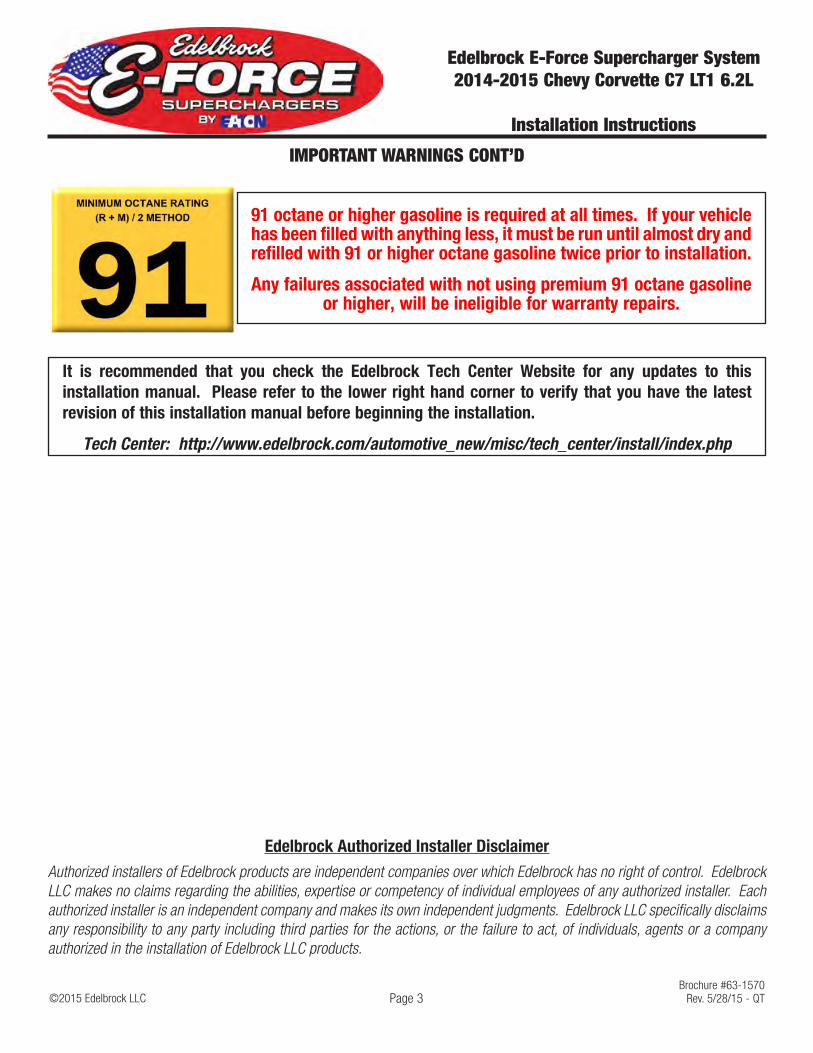
91 octane or higher gasoline is required at all times. If your vehicle has been filled with anything less, it must be run until almost dry and refilled with 91 or higher octane gasoline twice prior to installation.
Any failures associated with not using premium 91 octane gasoline or higher, will be ineligible for warranty repairs.
IMPORTANT WARNINGS CONT’D
Edelbrock Authorized Installer DisclaimerAuthorized installers of Edelbrock products are independent companies over which Edelbrock has no right of control. Edelbrock LLC makes no claims regarding the abilities, expertise or competency of individual employees of any authorized installer. Each authorized installer is an independent company and makes its own independent judgments. Edelbrock LLC specifically disclaims any responsibility to any party including third parties for the actions, or the failure to act, of individuals, agents or a company authorized in the installation of Edelbrock LLC products.
Edelbrock E-Force Supercharger System 2014-2015 Chevy Corvette C7 LT1 6.2L
Installation Instructions
Page 4©2015 Edelbrock LLCBrochure #63-1570
Rev. 5/28/15 - QT
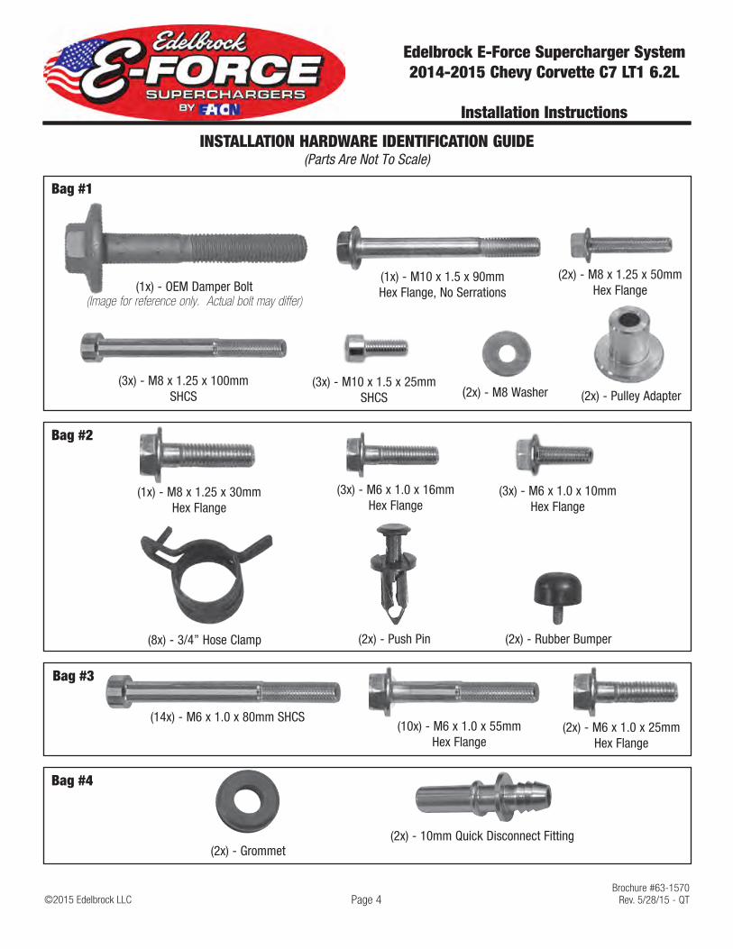
Bag #1
(2x) - M8 x 1.25 x 50mm Hex Flange
(2x) - M8 Washer
INSTALLATION HARDWARE IDENTIFICATION GUIDE (Parts Are Not To Scale)
(3x) - M8 x 1.25 x 100mm SHCS
(1x) - M10 x 1.5 x 90mm Hex Flange, No Serrations
(3x) - M10 x 1.5 x 25mm SHCS
(1x) - OEM Damper Bolt(Image for reference only. Actual bolt may differ)
(2x) - Pulley Adapter
(2x) - Push Pin
(3x) - M6 x 1.0 x 16mm Hex Flange
(3x) - M6 x 1.0 x 10mm Hex Flange
(1x) - M8 x 1.25 x 30mm Hex Flange
(2x) - Rubber Bumper(8x) - 3/4” Hose Clamp
Bag #2
(2x) - M6 x 1.0 x 25mm Hex Flange
(14x) - M6 x 1.0 x 80mm SHCS
Bag #3
(10x) - M6 x 1.0 x 55mm Hex Flange
(2x) - Grommet
Bag #4
(2x) - 10mm Quick Disconnect Fitting

Edelbrock E-Force Supercharger System 2014-2015 Chevy Corvette C7 LT1 6.2L
Installation Instructions
Page 5©2015 Edelbrock LLCBrochure #63-1570
Rev. 5/28/15 - QT
BRACKET AND FEAD IDENTIFICATION GUIDE(Parts Are Not To Scale)
Water Pump Bracket
Recovery Tank Bracket
Tensioner / Idler Bracket
Water Pump Isolator
Crank Pulley, S/C DriveDamper
Tensioner
Smooth Idler Pulley
Grooved Idler Pulley
Side Cover Brackets

Edelbrock E-Force Supercharger System 2014-2015 Chevy Corvette C7 LT1 6.2L
Installation Instructions
Page 6©2015 Edelbrock LLCBrochure #63-1570
Rev. 5/28/15 - QT
HOSE IDENTIFICATION GUIDE(Parts Are Not To Scale)
Water Pump to LTR Hose
Manifold to LTR Hose
Manifold To Recovery Tank
Recover Tank to Water Pump
EVAP - Firewall to EVAP
PCV - Nose to Valley
1/4” Hose (3’) 3/8” Hose (2.5’)

Edelbrock E-Force Supercharger System 2014-2015 Chevy Corvette C7 LT1 6.2L
Installation Instructions
Page 7©2015 Edelbrock LLCBrochure #63-1570
Rev. 5/28/15 - QT
HOSE ROUTING DIAGRAM
Heat Exchanger (LTR) Water Pump
Intercooler Reservoir Tank
Supercharger

Edelbrock E-Force Supercharger System 2014-2015 Chevy Corvette C7 LT1 6.2L
Installation Instructions
Page 8©2015 Edelbrock LLCBrochure #63-1570
Rev. 5/28/15 - QT
WIRE HARNESS GUIDE(Parts Are Not To Scale)
Constant +12v Power Wire
EVAP Engine Harness
TMAP Sensor
Fuse
RelayGround Strap
Intercooler Water Pump
MAF Sensor Engine Harness
MAP Sensor Engine Harness
EVAP Solenoid
MAF Sensor
TMAP HARNESS
WATER PUMP HARNESS

©2015 Edelbrock LLCBrochure #63-1570
Rev. 5/28/15 - QT
Edelbrock E-Force Supercharger System 2014-2015 Chevy Corvette C7 LT1 6.2L
Installation Instructions
Page 9
SUPERCHARGER INSTALLATION
WARNING: Battery must be sufficiently charged before starting the PCM flashing procedure.
Only begin the PCM flashing procedure when you have downloaded the calibration file from the Edelbrock Calibration Team to the handheld programmer. Do not flash the PCM until you are ready to install the supercharger. Once the PCM is flashed, DO NOT START the engine until the installation of the E-Force supercharger is complete.
1. Put the car into ACC mode, but don’t start the vehicle.
2. Connect the supplied PCM cable on the handheld programmer to the OBD-II connector located below the steering wheel, and to the left of your knee.
3. Use the directional pad to highlight the Program Vehicle option and press the Select button.
4. Use the directional pad to highlight the Pre-programmed Tune option and press the Select button.
5. Read the disclaimer then press Select to continue.
6. Verify that the ignition is in the ‘Key On’ position and that the engine is not running, then press Select.
7. Use the directional pad to highlight your vehicle and transmission combination then press Select.
8. Use the directional pad to highlight the Begin Program option then press Select.
9. Depending on your specific drivetrain configuration, several separate operations may take place during this step. Completion of each operation will cause the progress bar to reset to zero.
10. DO NOT unplug the programmer until prompted.
11. Turn the vehicle off when prompted to do so by the handheld programmer.
12. Read the parting message from programmer then press Select to continue.
13. Unplug the programmer cable from the OBD-II port. This concludes the PCM flashing procedure. DO NOT start the engine until the supercharger installation is complete.
14. Open the trunk and lift up the carpet on the passenger side of the vehicle to access the battery. Using a 10mm socket, disconnect the negative battery terminal.
15. Raise the vehicle with a service lift or equivalent.
16. Using a 7mm socket, remove six (6) bolts securing the front splash guard to the front fascia. Using a 10mm socket, remove four (4) additional bolts securing the splash guard the support brace. Remove the splash guard and set aside.

©2015 Edelbrock LLCBrochure #63-1570
Rev. 5/28/15 - QT
Edelbrock E-Force Supercharger System 2014-2015 Chevy Corvette C7 LT1 6.2L
Installation Instructions
Page 10
17. Using a 10mm socket, remove three (3) bolts securing the rear splash guard and remove.
18. Drain the coolant by removing the petcock on the lower driver side of the radiator.
19. Using a 7mm socket, remove four (4) bolts securing the factory air duct. Remove air duct and set aside.
20. Disconnect the passenger side and driver side PCV hoses from the air inlet tube. The driver side PCV can be removed from the valve cover barb as well. Do not discard as both hoses will be reused.
21. Disengage the locking tab on the MAF sensor harness and unplug the MAF sensor harness.
22. Using a flat head screwdriver, loosen the worm clamps on the air inlet tube. Remove the air inlet tube from the throttle body and airbox.
23. Carefully lift up the side engine covers to disengage and remove.
24. Disengage the locking tab on the MAP sensor harness and unplug the MAP sensor harness.
25. Using side cutters, remove the wire ties securing the engine harness to the top engine cover.
©2015 Edelbrock LLCBrochure #63-1570
Rev. 5/28/15 - QT
Edelbrock E-Force Supercharger System 2014-2015 Chevy Corvette C7 LT1 6.2L
Installation Instructions
Page 11
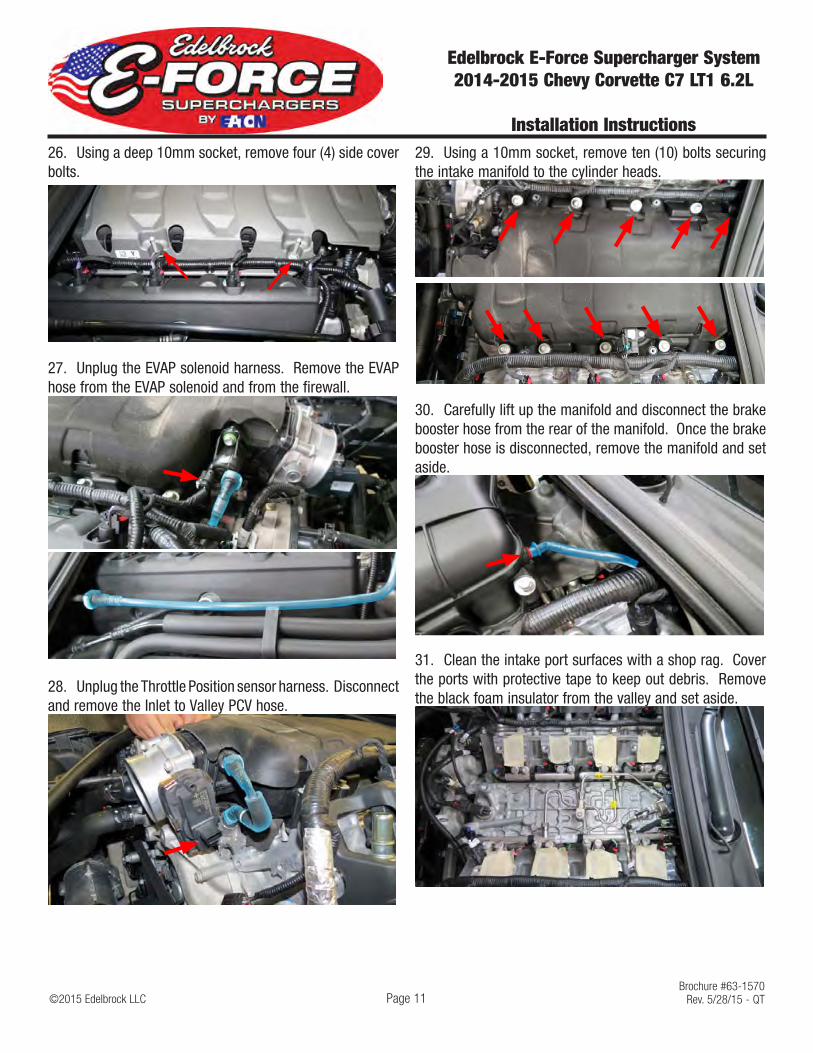
26. Using a deep 10mm socket, remove four (4) side cover bolts.
27. Unplug the EVAP solenoid harness. Remove the EVAP hose from the EVAP solenoid and from the firewall.
28. Unplug the Throttle Position sensor harness. Disconnect and remove the Inlet to Valley PCV hose.
29. Using a 10mm socket, remove ten (10) bolts securing the intake manifold to the cylinder heads.
30. Carefully lift up the manifold and disconnect the brake booster hose from the rear of the manifold. Once the brake booster hose is disconnected, remove the manifold and set aside.
31. Clean the intake port surfaces with a shop rag. Cover the ports with protective tape to keep out debris. Remove the black foam insulator from the valley and set aside.

©2015 Edelbrock LLCBrochure #63-1570
Rev. 5/28/15 - QT
Edelbrock E-Force Supercharger System 2014-2015 Chevy Corvette C7 LT1 6.2L
Installation Instructions
Page 12
32. Using a Torx T30, remove two bolts securing the driver side coil cover and remove.
33. Remove the retaining clip on the fuel line. Using a 3/8” fuel line tool, disconnect the fuel line from the fuel line extension. CAUTION: Place a shop rag around the fuel line to prevent fuel from spraying.
34. Using a 10mm socket, remove the bolt securing the fuel line extension to the valve cover. Remove the retaining clip on the fuel line extension. Then remove the fuel line extension from the fuel pump using a 3/8” fuel line tool.
35. Install the supplied fuel line extension onto the fuel pump barb.
36. Loosely secure the fuel line extension to the valve cover using the factory bolt. Apply Blue thread locker to the threads of the fuel line extension lock nut. Using a 11/16” wrench, secure the fuel line extension to the fuel pump using the lock nut. Tighten the lock nut, DO NOT OVER TIGHTEN. Securely fasten the factory fuel line extension bolt and fasten the set screw using a 9/64” hex wrench.
37. Unplug the brake booster check valve harness connector. Remove the check valve from the brake booster and from the canister. Set the brake booster hose assembly aside as it will be reused later.
Harness Connector

©2015 Edelbrock LLCBrochure #63-1570
Rev. 5/28/15 - QT
Edelbrock E-Force Supercharger System 2014-2015 Chevy Corvette C7 LT1 6.2L
Installation Instructions
Page 13
38. Remove the upper and lower radiator hoses with an appropriate hose clamp tool. NOTE: Factory hose clamps may be glued to the radiator hoses. Avoid rotating the hose clamps as radiator hoses may tear.
39. Disconnect two (2) radiator hose support rings from the fan assembly with a panel remover.
40. Disconnect the overflow/purge tube from the upper right radiator. Remove the retaining clip from the accessory cooler return hose, located on the lower left of the radiator, with a small flathead screwdriver. Remove the hose and set the retaining clip aside as it will be reused later.
41. Unplug the electric fan assembly.
42. Using a 10mm socket, remove two (2) bolts securing the fan assembly to the radiator. Lift fan assembly upwards and remove.
43. Using a 13mm socket, remove two (2) bolts securing the radiator and condenser assembly.
44. Disconnect the A/C condenser connector, right of the radiator, to prevent the connector from getting damaged.
©2015 Edelbrock LLCBrochure #63-1570
Rev. 5/28/15 - QT
Edelbrock E-Force Supercharger System 2014-2015 Chevy Corvette C7 LT1 6.2L
Installation Instructions
Page 14
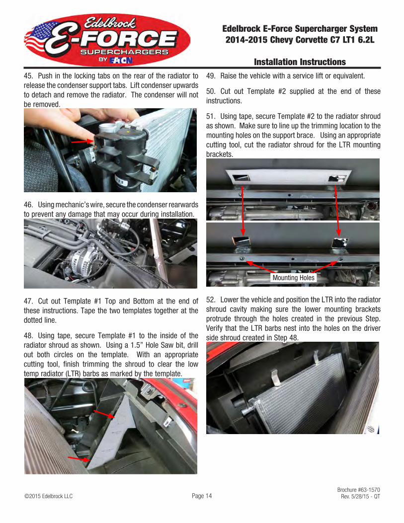
45. Push in the locking tabs on the rear of the radiator to release the condenser support tabs. Lift condenser upwards to detach and remove the radiator. The condenser will not be removed.
46. Using mechanic’s wire, secure the condenser rearwards to prevent any damage that may occur during installation.
47. Cut out Template #1 Top and Bottom at the end of these instructions. Tape the two templates together at the dotted line.
48. Using tape, secure Template #1 to the inside of the radiator shroud as shown. Using a 1.5” Hole Saw bit, drill out both circles on the template. With an appropriate cutting tool, finish trimming the shroud to clear the low temp radiator (LTR) barbs as marked by the template.
49. Raise the vehicle with a service lift or equivalent.
50. Cut out Template #2 supplied at the end of these instructions.
51. Using tape, secure Template #2 to the radiator shroud as shown. Make sure to line up the trimming location to the mounting holes on the support brace. Using an appropriate cutting tool, cut the radiator shroud for the LTR mounting brackets.
Mounting Holes
52. Lower the vehicle and position the LTR into the radiator shroud cavity making sure the lower mounting brackets protrude through the holes created in the previous Step. Verify that the LTR barbs nest into the holes on the driver side shroud created in Step 48.

©2015 Edelbrock LLCBrochure #63-1570
Rev. 5/28/15 - QT
Edelbrock E-Force Supercharger System 2014-2015 Chevy Corvette C7 LT1 6.2L
Installation Instructions
Page 15
53. Raise the vehicle with a service lift or equivalent. Using a 10mm socket, temporarily secure the LTR to the radiator support using the factory bolts.
54. Lower the vehicle. Using a drill with an 8mm bit, carefully drill through the plastic radiator shroud using the holes on the LTR brackets as guides. Secure the LTR to the radiator shroud with the supplied push pins from Bag #2.
55. With the LTR installed, temporally reposition the A/C condenser in its factory location.
56. Using a ratchet strap or equivalent, secure the steering wheel to prevent it from rotating. WARNING: Damage to the SIR coil may result from rotation of the steering wheel and/or front tires once the intermediate steering shaft is disconnected.
57. Using an 11mm socket, unbolt the intermediate steering shaft from the steering rack.
58. Support the hood with a sturdy hood prop. Using a small flathead screwdriver, remove both hood dampers and set aside.
59. Unplug all three (3) connectors from the electronic power steering module.
60. Disconnect the chassis harness and the brake control module harness.

©2015 Edelbrock LLCBrochure #63-1570
Rev. 5/28/15 - QT
Edelbrock E-Force Supercharger System 2014-2015 Chevy Corvette C7 LT1 6.2L
Installation Instructions
Page 16
61. Raise the vehicle with a service lift or equivalent.
62. Using a 13mm socket, remove two (2) bolts securing the starter.
63. Remove three (3) bolts securing the starter’s heat shield using a 10mm socket.
64. Using a 10mm socket, remove the dust cover and position the starter rearwards to install a GM flywheel holder. NOTE: Starter does not have to be completely removed.
65. Using a Torx T15, remove four (4) bolts securing the passenger side brake cooler duct. Repeat for the driver side brake cooler duct.
66. Unbolt the driver and passenger sway bar end links using 8mm and 18mm wrenches.
67. Note the orientation of the sway bar. Using a 15mm and 18mm socket, remove four (4) bolts securing the sway bar assembly to the subframe. Carefully remove the sway bar assembly and set aside.
68. Using a 10mm socket, remove two (2) nuts and washers securing the brake control module to the support bracket. TIP: These nuts are easier to remove from the top. Washers may be stuck to rubber grommets, carefully remove w/ a small flathead screwdriver.
69. Using a 13mm socket, remove two bolts securing the brake control module support bracket. Remove the harness retaining push pin and remove the bracket.

©2015 Edelbrock LLCBrochure #63-1570
Rev. 5/28/15 - QT
Edelbrock E-Force Supercharger System 2014-2015 Chevy Corvette C7 LT1 6.2L
Installation Instructions
Page 17
70. Using an 18mm socket, unbolt two (2) bolts securing the steering rack and carefully rotate the rack towards the front of the vehicle.
71. Secure the steering rack in the forward position with mechanic’s wire and lower the vehicle.
72. Using a 15mm socket, rotate the tensioner clockwise and remove the stock drive belt.
73. Using a 24mm socket and a breaker bar, remove the factory harmonic balancer bolt. Do not discard bolt as it will be used during the installation procedure.
74. Remove the factory harmonic balancer using a Claw-Type Damper Puller.
NOTE: Dry sump and Wet sump vehicles use different harmonic balancers and balancer bolts. Please verify that you have the correct parts before proceeding.
Dry Sump Damper - 2.783” Total WidthDry Sump Bolt - GM 11570163
Wet Sump Damper - 3.464” Total WidthWet Sump Bolt - GM 12557840
75. Apply white grease to the snout of the crank and to the inside of the balancer hub. Apply clean engine oil to the outside of the balancer hub. NOTE: Also apply black silicone to the key way on the damper to prevent possible oil leaks.
76. Line up the key on the crank with the key way on the harmonic balancer. Install the supplied harmonic balancer using an appropriate harmonic balancer installation tool. NOTE: The balancer should be positioned onto the end of the crankshaft as straight as possible prior to tool installation.

©2015 Edelbrock LLCBrochure #63-1570
Rev. 5/28/15 - QT
Edelbrock E-Force Supercharger System 2014-2015 Chevy Corvette C7 LT1 6.2L
Installation Instructions
Page 18
77. Using a 24mm socket and a torque wrench, install the used factory balancer bolt and torque it to 240 ft-lbs. Then remove the factory balancer bolt and discard.
NOTE: The nose of the crankshaft should be recessed 2.4–4.48 mm (0.094–0.176”in) into the balancer bore. Measure for a correctly installed balancer. If the balancer is not installed to the proper dimensions, repeat the installation procedure until the proper dimensions are achieved.
78. Using a 24mm socket and a torque wrench, install the new supplied balancer bolt and torque it to 110 ft-lbs. Loosen the bolt 360° and re-torque the bolt to 59 ft-lbs. + an additional 200° of rotation.
79. Install the supplied balancer pulley onto the balancer. Apply Blue thread locker to the three (3) M10 x 25mm SHCS bolts from Bag #1. Using an 8mm Hex key, secure the balancer pulley to the balancer. Torque bolts to 18 ft-lbs.
80. Using the diagram below, reinstall the factory drive belt to the 6 rib portion of the crank pulley.
81. Using a 13mm socket, remove three (3) bolts from the factory water pump.
82. Apply Blue thread locker to the three (3) M8 x 100mm SHCS bolts from Bag #1. Using a 6mm Hex key, install the FEAD bracket to the water pump. Torque bolts to 22 ft-lbs.
83. Insert the supplied pulley adapters to the backside of the supplied grooved and smooth idler pulleys.
84. Using the M8 washers and M8 x 50mm bolts brom Bag #1, install the idler pulleys to the FEAD bracket with a 13mm socket. Torque both bolts to 18 ft-lbs. NOTE: The smooth idler pulley will install in the top location.

©2015 Edelbrock LLCBrochure #63-1570
Rev. 5/28/15 - QT
Edelbrock E-Force Supercharger System 2014-2015 Chevy Corvette C7 LT1 6.2L
Installation Instructions
Page 19
85. Using an 18mm socket, reinstall the steering rack making sure the intermediate steering shaft is properly seated. Torque the steering rack bolts to 92 ft-lbs.
86. Using an 11mm socket, reinstall the factory steering rack pinch bolt to secure the intermediate steering shaft. Torque pinch bolt to 18 ft-lbs.
87. Using a 15mm and 18mm socket, reinstall the sway bar assembly. Torque sway bar assembly bolts to 44 ft-lbs.
88. Using an 8mm and 18mm wrench, reinstall the sway bar end links. Torque end links to 44 ft-lbs + 30°.
89. Using a Torx T15 drive, reinstall both driver side and passenger side brake cooler ducts.
90. Reinstall the brake control module to the module bracket using the two (2) factory nuts and washers. Reinstall the brake control module bracket using a 13mm socket. Torque bracket bolts to 18 ft-lbs.
91. Reconnect all steering and brake module connectors.
92. Remove the flywheel holding tool and reinstall the starter heat shield and dust cover using a 10mm socket. Reinstall the starter using the stock bolts and an 11mm socket. Torque starter bolts to 37 ft-lbs.
93. Reinstall both hood dampers and remove the ratchet strap securing the steering wheel.
94. Install the LTR to Manifold hose onto the top barb of the LTR. Secure with a hose clamp from Bag #2. NOTE: 90° end goes onto the LTR.
95. Install the LTR to Water Pump hose onto the lower barb of the LTR. Secure with a hose clamp from Bag #2. NOTE: longer end goes onto the LTR.
96. Install the water pump isolator onto the water pump bracket. Install the water pump onto the water pump isolator.
97. Move the driver side brake air duct by removing one 10mm bolt, one T15 Torx and one push pin.
98. Using a 10mm wrench and two (2) M6 x 16mm bolts from Bag #2, secure the water pump assembly to the support brace adjacent to the air duct.

©2015 Edelbrock LLCBrochure #63-1570
Rev. 5/28/15 - QT
Edelbrock E-Force Supercharger System 2014-2015 Chevy Corvette C7 LT1 6.2L
Installation Instructions
Page 20
99. Using a hose clamp from Bag #2, secure the LTR to Water Pump hose to the water pump outlet.
100. Reattach the condenser to the radiator and reinstall the assembly using a 10mm socket. Reinstall the electric fan using a 10mm socket. Reconnect the lower left accessory cooler hose and both radiator hoses. Re-secure the lower radiator hose to the electronic fan. Reconnect electric fan and A/C condenser connectors.
101. Using a razor blade or equivalent, cut out the fuel line relief on the foam valley insulator.
102. Reinstall the foam valley insulator into the valley making sure it is seated properly.
103. Remove the factory O-ring gaskets from the intake manifold.
104. Clean and inspect the O-ring gaskets. Replace torn or damage O-rings as needed. Using a razor blade, or equivalent, remove the tips off all eight (8) factory O-ring gaskets.
105. Install four (4) modified O-ring gaskets onto the passenger side E-Force runner. NOTE: Driver side runner will have a slot for the fuel line, the passenger side runner will not.
©2015 Edelbrock LLCBrochure #63-1570
Rev. 5/28/15 - QT
Edelbrock E-Force Supercharger System 2014-2015 Chevy Corvette C7 LT1 6.2L
Installation Instructions
Page 21
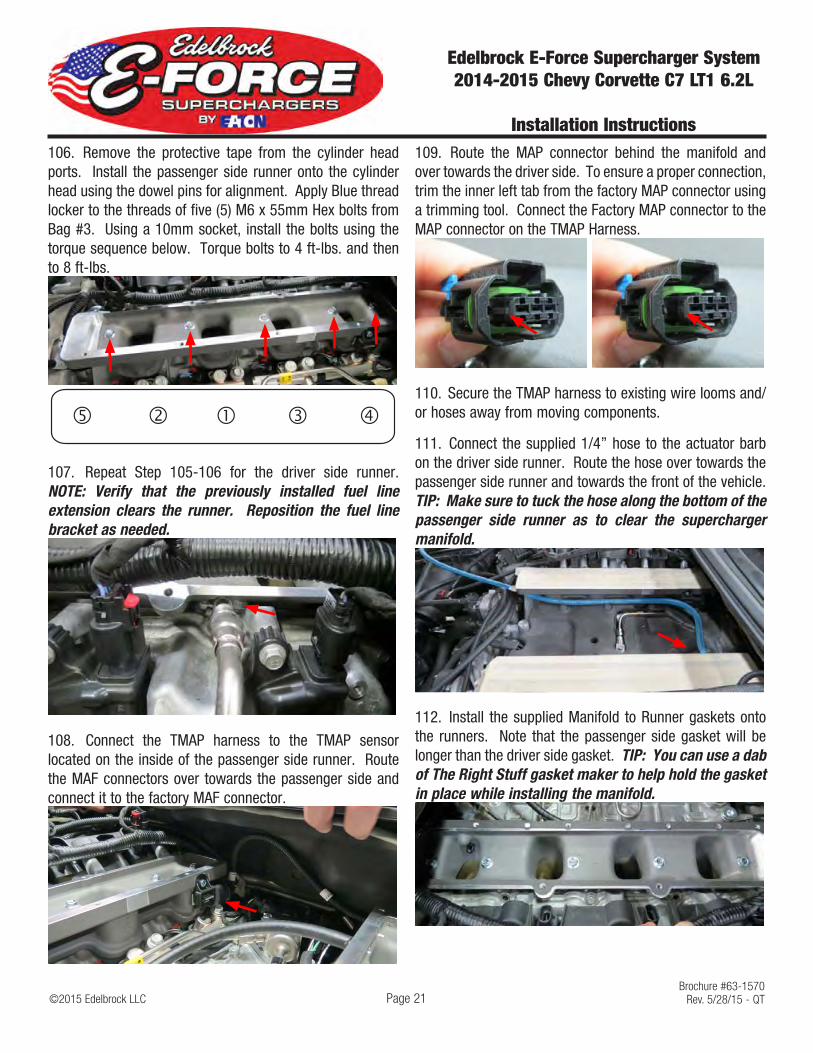
106. Remove the protective tape from the cylinder head ports. Install the passenger side runner onto the cylinder head using the dowel pins for alignment. Apply Blue thread locker to the threads of five (5) M6 x 55mm Hex bolts from Bag #3. Using a 10mm socket, install the bolts using the torque sequence below. Torque bolts to 4 ft-lbs. and then to 8 ft-lbs.
� � � ��
107. Repeat Step 105-106 for the driver side runner. NOTE: Verify that the previously installed fuel line extension clears the runner. Reposition the fuel line bracket as needed.
108. Connect the TMAP harness to the TMAP sensor located on the inside of the passenger side runner. Route the MAF connectors over towards the passenger side and connect it to the factory MAF connector.
109. Route the MAP connector behind the manifold and over towards the driver side. To ensure a proper connection, trim the inner left tab from the factory MAP connector using a trimming tool. Connect the Factory MAP connector to the MAP connector on the TMAP Harness.
110. Secure the TMAP harness to existing wire looms and/or hoses away from moving components.
111. Connect the supplied 1/4” hose to the actuator barb on the driver side runner. Route the hose over towards the passenger side runner and towards the front of the vehicle. TIP: Make sure to tuck the hose along the bottom of the passenger side runner as to clear the supercharger manifold.
112. Install the supplied Manifold to Runner gaskets onto the runners. Note that the passenger side gasket will be longer than the driver side gasket. TIP: You can use a dab of The Right Stuff gasket maker to help hold the gasket in place while installing the manifold.

©2015 Edelbrock LLCBrochure #63-1570
Rev. 5/28/15 - QT
Edelbrock E-Force Supercharger System 2014-2015 Chevy Corvette C7 LT1 6.2L
Installation Instructions
Page 22
113. Using a 10mm socket, remove the EVAP solenoid from the stock manifold and install it onto the supercharger manifold using the stock EVAP solenoid bolt. With help from an assistant, carefully lower the supercharger manifold onto the runners. CAUTION: Verify that the runner gaskets are properly aligned before proceeding.
114. Apply Blue thread locker to the fourteen (14) M6 x 80mm SHCS bolts and two (2) M6 x 25mm Hex bolts from Bag #3. Place the bolts into their provisions noting that location 13 and 16 will use the M6 x25mm bolts. Using a 5mm Hex drive and a 10mm socket, secure the manifold to the engine using the torque sequence below. Torque bolts to 4 ft-lbs. and then to 8 ft-lbs.
1
23
4
5
6
7
8
9
1011
12
13
14
15
16
FRONTM6 x 25mm
115. Connect the 90° fitting on the Nose to Valley PCV to the upper barb on the throttle body flange. Route the other end under the nose to the barb located on the valley.
116. Connect the Straight fitting on the EVAP hose to the fitting located on the firewall. Route the EVAP hose along the coil cover and under the water crossover, over towards the EVAP solenoid.
117. Connect the EVAP hose to the EVAP installed under the supercharger nose. Secure EVAP hose to existing engine harnesses or hoses away from moving components.
118. Using a cutting tool, carefully remove the two check valves, brake booster fitting, canister fitting and T fitting from the factory brake booster hose assembly.

©2015 Edelbrock LLCBrochure #63-1570
Rev. 5/28/15 - QT
Edelbrock E-Force Supercharger System 2014-2015 Chevy Corvette C7 LT1 6.2L
Installation Instructions
Page 23
119. Using the supplied 3/8” hose, the factor brake booster check valves and fittings, assemble the new brake booster hose according to the diagram below. Note that the check valves are directional as illustrated by the white arrows.
6”4”2”16”
120. Connect the new brake booster hose assembly to the brake booster and canister. Route the 16” end towards the nose of the supercharger and connect it to the lower barb on the throttle body flange. Reconnect the brake booster harness connector and secure hose assembly away from moving and hot components.
121. Install the rubber bumpers from Bag #2 onto the recovery tank as shown.
122. Using a 10mm socket and three (3) M6 x 10mm bolts from Bag #2, secure the recovery tank bracket and the relay on the supplied water pump harness to the recovery tank.
123. Using a panel puller, remove the christmas tree clips securing the engine harness next to the brake control module. Using a 10mm socket, remove the bolt securing the ground strap from the same engine harness.
124. Using a 10mm socket and the factory ground strap bolt, secure the recovery tank assembly along with the factory ground and the ground strap on the water pump harness, to the factory ground location. Using a 10mm socket and a M6 x 16mm bolt from Bag #2, secure the recovery tank to the christmas tree location from the previous step.

©2015 Edelbrock LLCBrochure #63-1570
Rev. 5/28/15 - QT
Edelbrock E-Force Supercharger System 2014-2015 Chevy Corvette C7 LT1 6.2L
Installation Instructions
Page 24
125. Route the water pump connector down towards water pump and connect to the water pump.
126. Connect the factory EVAP connector to the EVAP connector on the water pump harness. Connect the EVAP connector on the water pump harness to the EVAP solenoid.
127. Route the fuse and Power connector over towards the alternator. Using a 13mm socket, remove the nut securing the power cable and install the water pump power connector.
128. Secure the Water Pump harness to existing wire looms and/or hoses away from moving and hot components.
129. Carefully install the 10 rib supercharger belt between the steering rack and supercharger drive pulley.
130. Position the supercharger belt around the supplied tensioner and install the tensioner onto the FEAD bracket using a 15mm socket and a M10 x 90mm Hex Flange bolt. Torque tensioner bolt to 32 ft-lbs.
131. Using a breaker bar, rotate the tensioner counterclockwise and install the supercharger belt using the routing diagram below.

©2015 Edelbrock LLCBrochure #63-1570
Rev. 5/28/15 - QT
Edelbrock E-Force Supercharger System 2014-2015 Chevy Corvette C7 LT1 6.2L
Installation Instructions
Page 25
132. Using two (2) hose clamps from Bag #2, secure the Recovery Tank to Water Pump hose onto the bottom barb on the tank and to the inlet barb of the water pump.
133. Connect the previously installed, LTR to Manifold hose, to the lower barb on the water crossover. Secure hose with a hose clamp from Bag #2.
134. Connect the Tank to Manifold hose to the upper barb on the water crossover. Secure the hose with two (2) hose clamps from Bag #2.
135. Connect the previously installed actuator PCV hose to the actuator.
136. Using a 10mm socket, remove the throttle body from the stock manifold and install it onto the supercharger manifold using the factory throttle body gasket and bolts.
137. Using a 10mm socket, remove the 2nd and 3rd bolt from the driver side valve cover.
138. Using a Torx T30, loosen the passenger side coil cover and remove the 2nd and 4th valve cover bolts.
139. Remove the rubber side cover supports from the factory side covers. Using a little lube, install the rubber side cover supports onto the supplied side cover brackets.

©2015 Edelbrock LLCBrochure #63-1570
Rev. 5/28/15 - QT
Edelbrock E-Force Supercharger System 2014-2015 Chevy Corvette C7 LT1 6.2L
Installation Instructions
Page 26
140. Using a 10mm socket and the stock valve cover bolts, install the side cover brackets to the valve cover. Re-secure the passenger side coil cover.
141. Using an appropriate cutting tool, trim the driver side coil covers to clear the supercharger manifold and the fuel line extension. TIP: It’s recommended to test fit the coil cover frequently to avoid over trimming the coil cover. Reinstall the passenger side coil cover once proper fitment is verified.
142. Using a Torx T15, remove the rear section of the factory airbox and replace the air filter with the supplied, reusable, green filter. Reinstall the rear section of the airbox.
143. Install the supplied grommets and Quick Disconnect fittings from Bag #4 onto the supplied air inlet tube.
144. Install the hump coupler onto the airbox. Install the air inlet tube onto the airbox and then onto the throttle body using the straight couplers. Secure with supplied worm clamps.
NOTE: Some trimming of the tab protruding on the fan may be required.

©2015 Edelbrock LLCBrochure #63-1570
Rev. 5/28/15 - QT
Edelbrock E-Force Supercharger System 2014-2015 Chevy Corvette C7 LT1 6.2L
Installation Instructions
Page 27
145. Connect the factory driver side PCV hose onto the barb located on the driver side valve cover and onto the air inlet tube.
146. Connect the passenger side PCV hose to the barb on the air inlet tube.
147. Using a 7mm socket, reinstall the factory front air duct using the factory hardware.
148. Install the supplied support barbs onto the side covers with a 10mm socket.
149. Install the side covers onto the side cover brackets.
150. Fill the radiator reservoir tank with GM recommended 50/50 coolant blend.
151. Fill the supercharger recovery tank with 50/50 coolant and water blend. Recheck the coolant level once the water pump has cycled a few times.
152. Reconnect the battery and switch ignition to the ON position, DO NOT START. With the ignition switch on, check for any coolant or fuel leaks. Repair all leaks before proceeding. If no leaks are present the installation is complete.
NOTE: Slight modification to the factory hoodliner is recommended to improved supercharger clearance. This procedure isn’t required, but is highly recommended as the hoodliner may come in contact with the supercharger and scuff the finish of the powder coat.
153. Carefully follow the procedure to modify the hoodliner. The modification consist of partially cutting the hoodliner along the embossing and securing the modified portion to the hood. The red dotted line below represents where the hoodliner has to be cut and secured.

©2015 Edelbrock LLCBrochure #63-1570
Rev. 5/28/15 - QT
Edelbrock E-Force Supercharger System 2014-2015 Chevy Corvette C7 LT1 6.2L
Installation Instructions
Page 28
154. Remove two (2) screws using a T-15 Torx screwdriver. Carefully pull the air duct outwards to release from the hoodliner.
155. Carefully remove six (6) tree pins using a panel puller. Lift hoodliner upwards to remove from the hood. NOTE: Proceed with caution as the hoodliner is easily damaged.
156. Lay the hoodliner on a clean flat working surface with the engine side facing up. Using a measuring tape and marker, mark the hoodliner 7” from the air duct opening along the left and right vertical embossing. NOTE: This should be done on the engine side of the hoodliner as the vertical embossing is more pronounced.
7” 7”Vertical
Embossing
157. Using a straight edge and sharp utility knife, carefully cut the hoodliner along the left vertical embossing starting from the 7” mark and slowly working your way down towards the air duct opening. Once the cut is 3” long, stop and turn the hoodliner over.
158. Turn the hoodliner over so the hood side is facing upwards, continue the cut just to the top of the horizontal embossing (see red dotted line from image on Step #153). DO NOT allow the cut to continue into the embossed area as it will not secure properly to the hood. The total length of the cut should be approximately 3.5”. Repeat Steps #157-158 to cut the right vertical embossing.

©2015 Edelbrock LLCBrochure #63-1570
Rev. 5/28/15 - QT
Edelbrock E-Force Supercharger System 2014-2015 Chevy Corvette C7 LT1 6.2L
Installation Instructions
Page 29
159. With the hood side of the hoodliner facing upwards, cut the top horizontal embossing using a straight edge and sharp utility knife. NOTE: The cut must remain 1-2mm above the embossing. The final product should look like the image on Step 160.
160. The finished hoodliner should look like the image below.
161. Using a measuring tape, mark the horizontal hood brace 12” from the inside of the vertical hood brace. Do this for both sides.
12”
162. With the support bracket locations marked, position the left (driver side) bracket onto the flat portion of the horizontal support brace, right of the 12” mark.
163. Using the bracket as a template, drill out one mounting hole using a #30 drill bit.
164. Insert a supplied rivet into the hole to temporally secure the bracket and drill out the other mounting hole. Remove the rivet and bracket.
165. Repeat Steps #162-164 for the right bracket noting that the bracket will be installed to the left of the 12” mark.

©2015 Edelbrock LLCBrochure #63-1570
Rev. 5/28/15 - QT
Edelbrock E-Force Supercharger System 2014-2015 Chevy Corvette C7 LT1 6.2L
Installation Instructions
Page 30
NOTE: Step #166 is not required but will prevent the original color of the hood from showing through the modified hoodliner. This step is not required on black or dark colored vehicles.
166. Carefully mask off the vehicle to protect from any overspray that may occur during this procedure. Using black spray paint, spray the center section of the horizontal hood brace as shown. Allow paint adequate time to dry and remove masking.
167. Using a rivet gun, secure both brackets to the horizontal hood brace.
168. With the help from an assistant, carefully reinstall the hoodliner making sure to secure the lower portion of the hoodliner first, then carefully position the modified portion of the hoodliner behind the support brackets. TIP: Use a credit card to guide the hoodliner behind the support bracket.
169. Adjust hoodliner as needed and resecure using six (6) factory tree pins.
170. Reinstall the air duct using the factory hardware.
NOTE: If the lower portion hoodliner overhangs the horizontal hood brace, additional trimming of the hoodliner may be required. The hoodliner needs to sit just below the horizontal hood brace. Verify the trimmed edge of the hoodliner provides adequate clearance to the front of the water crossover before continuing.
171. Using a paint brush and black enamel paint, carefully paint the exposed areas of the modified section of the hoodliner. Apply multiple layers as needed. This is to help keep the hoodliner from frizzing and give a more finished look. Allow adequate time to dry before closing the hood.
Congratulations on the successful installation of your new Edelbrock E-Force Supercharger System. If you have any questions, please call our Technical Support hotline at 800-416-8628 and one of our technicians will be happy to assist you.


THIS SIDE OUT
TEMPLATE #1 TOP


THIS SIDE OUT
TEMPLATE #1 BOTTOM


TEM
PLAT
E #2
THIS
SID
E O
UT