Embed Size (px)
Citation preview


©2004-2005 Dynojet Research, Inc. All Rights Reserved.
Eddy Current Brake Installation and User Guide For Model 224 Pit Automotive Dynamometers.
This manual is copyrighted by Dynojet Research, Inc., hereafter referred to as Dynojet, and all rights are reserved. This manual, and the software described in it, is furnished under license and may only be used or copied in accordance with the terms of such license. This manual is furnished for informational use only, is subject to change without notice, and should not be construed as a commitment by Dynojet. Dynojet assumes no responsibility or liability for any error or inaccuracies that may appear in this manual. Except as permitted by such license, no part of this manual may be reproduced, stored in a retrieval system, or transmitted, in any form or by any means, electronic, mechanical, recording, or otherwise, without the prior written permission of Dynojet.
The Dynojet logo is a trademark of Dynojet Research, Inc.
Any trademarks, trade names, service marks, or service names owned or registered by any other company and used in this guide are the property of their respective companies.
Dynojet Research, Inc., 2191 Mendenhall Drive, North Las Vegas, Nevada 89081, USA.
Printed in USA.
Part Number: 98215101 Version 2 (03/05)
#RECORD
Dynamometer Number: ____________________________________________________
Eddy Current Brake(Retarder) Number:_________________________________________________________

TABLE OF CONTENTS
Chapter 1 Eddy Current Brake InstallationIntroduction . . . . . . . . . . . . . . . . . . . . . . . . . . . . . . . . . . . . . . . . . . . . . . . . . .1-2
Conventions Used In This Manual . . . . . . . . . . . . . . . . . . . . . . . . . . . . . . .1-3Technical Support . . . . . . . . . . . . . . . . . . . . . . . . . . . . . . . . . . . . . . . . . . .1-3Parts List . . . . . . . . . . . . . . . . . . . . . . . . . . . . . . . . . . . . . . . . . . . . . . . . . .1-4
Power Requirements and Installation . . . . . . . . . . . . . . . . . . . . . . . . . . . . .1-5Installing the Wall Receptacle . . . . . . . . . . . . . . . . . . . . . . . . . . . . . . . . . . .1-5Testing for Correct Voltages . . . . . . . . . . . . . . . . . . . . . . . . . . . . . . . . . . . .1-6Replacing the Power Plug . . . . . . . . . . . . . . . . . . . . . . . . . . . . . . . . . . . . .1-7Hard Wiring to the Building . . . . . . . . . . . . . . . . . . . . . . . . . . . . . . . . . . . .1-7
Eddy Current Brake Installation . . . . . . . . . . . . . . . . . . . . . . . . . . . . . . . . . .1-8Before Installing the Eddy Current Brake: Verify Optimal Brake Cooling . . .1-8Unpacking the Eddy Current Brake . . . . . . . . . . . . . . . . . . . . . . . . . . . . . .1-9Installing the Bearing . . . . . . . . . . . . . . . . . . . . . . . . . . . . . . . . . . . . . . . .1-10Installing the Spline Shaft and Driveline Assembly . . . . . . . . . . . . . . . . . .1-11Installing the Eddy Current Brake . . . . . . . . . . . . . . . . . . . . . . . . . . . . . . .1-12Installing the Pit Cover Supports and Theta Controller . . . . . . . . . . . . . . .1-15Securing the Brake to the Dyno Pit Floor . . . . . . . . . . . . . . . . . . . . . . . . .1-17Routing the Brake Cables . . . . . . . . . . . . . . . . . . . . . . . . . . . . . . . . . . . . .1-18Wiring the Breakout Board . . . . . . . . . . . . . . . . . . . . . . . . . . . . . . . . . . . .1-19Replacing the Theta Controller Fuses . . . . . . . . . . . . . . . . . . . . . . . . . . . .1-21
Chapter 2 Torque Module InstallationLoad Cell Installation . . . . . . . . . . . . . . . . . . . . . . . . . . . . . . . . . . . . . . . . . . .2-2
Parts List . . . . . . . . . . . . . . . . . . . . . . . . . . . . . . . . . . . . . . . . . . . . . . . . . .2-2Installing the Load Cell . . . . . . . . . . . . . . . . . . . . . . . . . . . . . . . . . . . . . . .2-2
Torque Module Installation . . . . . . . . . . . . . . . . . . . . . . . . . . . . . . . . . . . . .2-4Accessing the Dyno Electronics . . . . . . . . . . . . . . . . . . . . . . . . . . . . . . . . .2-4Installing the Torque Module . . . . . . . . . . . . . . . . . . . . . . . . . . . . . . . . . . .2-5Routing the Load Cell Cable . . . . . . . . . . . . . . . . . . . . . . . . . . . . . . . . . . .2-7Installing the End Deck and Deck Assemblies . . . . . . . . . . . . . . . . . . . . . . .2-9
Load Cell Calibration . . . . . . . . . . . . . . . . . . . . . . . . . . . . . . . . . . . . . . . . .2-11
Model 224 Pit Eddy Current Brake Installation and User Guidei

TA B L E O F C O N T E N T S
Chapter 3 Basic Dynamometer OperationLoading the Car . . . . . . . . . . . . . . . . . . . . . . . . . . . . . . . . . . . . . . . . . . . . . . .3-2Connecting The RPM Pickup . . . . . . . . . . . . . . . . . . . . . . . . . . . . . . . . . . . .3-5
RPM Pickup Descriptions . . . . . . . . . . . . . . . . . . . . . . . . . . . . . . . . . . . . . .3-5Connecting the Secondary Inductive Pickup . . . . . . . . . . . . . . . . . . . . . . .3-6Connecting The Primary Inductive Pickup . . . . . . . . . . . . . . . . . . . . . . . . .3-7
Pre-run Inspection . . . . . . . . . . . . . . . . . . . . . . . . . . . . . . . . . . . . . . . . . . . . .3-8Before Starting the Engine . . . . . . . . . . . . . . . . . . . . . . . . . . . . . . . . . . . . .3-8Engine Warm Up . . . . . . . . . . . . . . . . . . . . . . . . . . . . . . . . . . . . . . . . . . . .3-9After Engine Warm Up . . . . . . . . . . . . . . . . . . . . . . . . . . . . . . . . . . . . . . . .3-9
Making a Test Run . . . . . . . . . . . . . . . . . . . . . . . . . . . . . . . . . . . . . . . . . . .3-10
Appendix A Red Head Anchor InstallationInstallation . . . . . . . . . . . . . . . . . . . . . . . . . . . . . . . . . . . . . . . . . . . . . . . . . . .A-2
Appendix B Power Requirements—Excluding North AmericaPower Requirements and Installation . . . . . . . . . . . . . . . . . . . . . . . . . . . . .B-2
Installing the Wall Receptacle . . . . . . . . . . . . . . . . . . . . . . . . . . . . . . . . . . .B-3Testing for Correct Voltages . . . . . . . . . . . . . . . . . . . . . . . . . . . . . . . . . . . .B-4Replacing the Power Plug . . . . . . . . . . . . . . . . . . . . . . . . . . . . . . . . . . . . .B-5Hard Wiring to the Building . . . . . . . . . . . . . . . . . . . . . . . . . . . . . . . . . . . .B-5
Appendix C Installing the Adapter and Bearing—Early Model DynamometersInstalling the Adapter and Bearing—Early Model Dynos . . . . . . . . . . . . .C-2
Index . . . . . . . . . . . . . . . . . . . . . . . . . . . . . . . . . . . . . . . . . . . . . . . . . Index-i
Model 224 Pit Eddy Current Brake Installation and User Guideii
C H A P T E R
1EDDY CURRENT BRAKE INSTALLATION
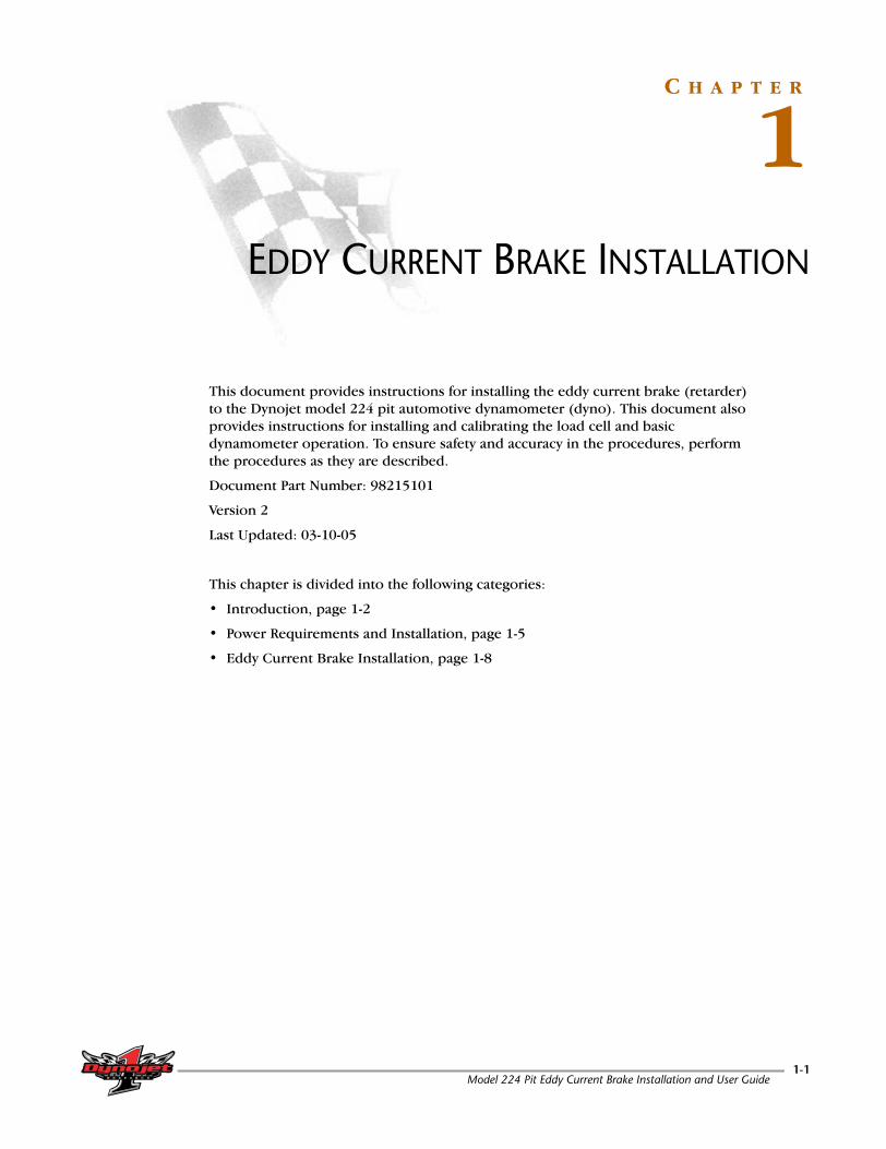
This document provides instructions for installing the eddy current brake (retarder) to the Dynojet model 224 pit automotive dynamometer (dyno). This document also provides instructions for installing and calibrating the load cell and basic dynamometer operation. To ensure safety and accuracy in the procedures, perform the procedures as they are described.
Document Part Number: 98215101
Version 2
Last Updated: 03-10-05
This chapter is divided into the following categories:
• Introduction, page 1-2
• Power Requirements and Installation, page 1-5
• Eddy Current Brake Installation, page 1-8
Model 224 Pit Eddy Current Brake Installation and User Guide1-1

C H A P T E R 1Introduction
. . . . . . . . . . . . . . . . . . . . . . . . . . . . . . . . . . .INTRODUCTION
Before installing your eddy current brake, please take a moment to read this guide for installation instructions and other important information.
This guide is designed to be a reference tool in your everyday work and includes the following chapters and information:
EDDY CURRENT BRAKE INSTALLATION
This chapter describes the procedures for installing the eddy current brake.
TORQUE MODULE INSTALLATION
This chapter describes the procedures for installing the torque module and load cell along with load cell calibration.
BASIC DYNO OPERATION
This chapter describes basic dyno operating procedures.
RED HEAD INSTALLATION
This appendix describes the procedures for installing the Red Head anchors.
POWER REQUIREMENTS—EXCLUDING NORTH AMERICA
This appendix describes the power requirements and installation instructions for all locations excluding North America.
INSTALLING THE ADAPTER AND BEARING—EARLY MODEL DYNOS
This appendix describes the procedures for installing the adapter and bearing needed for early model dynos.
Model 224 Pit Eddy Current Brake Installation and User Guide1-2

E D D Y C U R R E N T B R A K E I N S T A L L A T I O NIntroduction
CONVENTIONS USED IN THIS MANUAL
The conventions used in this manual are designed to protect both the user and the equipment.
TECHNICAL SUPPORT
For assistance, please contact Dynojet Technical Support at 1-800-992-3525, or write to Dynojet at 2191 Mendenhall Drive, North Las Vegas, NV 89081.
Visit us on the World Wide Web at www.dynojet.com where Dynojet provides state of the art technical support, on-line shopping, 3D visualizations, and press releases about our latest product line.
Example of Convention Description
The Caution icon indicates a potential hazard to the dynamometer equipment. Follow all procedures exactly as they are described and use care when performing all procedures.
The Warning icon indicates potential harm to the person performing a procedure and/or the dynamometer equipment.
#RECORDThe Record # icon reminds you to record your dynamometer and/or eddy current brake (retarder) number on the inside cover of this manual.
Bold Highlights items you can select on in the software interface, including buttons and menus.
The arrow indicates a menu choice. For example, “select File Open” means “select the File menu, then select the Open choice on the File menu.”
Version 2 Model 224 Pit Eddy Current Brake Installation and User Guide1-3

C H A P T E R 1Introduction
PARTS LIST
The following table lists all of the parts included in the Eddy Current Brake (P/N 72912002) Installation kit. Check your kit against the parts listed to make sure you have received all of the parts. If any part is missing, contact Dynojet Technical Support.
part number description quantity
21217200 Pit Cover Support 2
21217504 Hood Scoop 2
21217505 Hood Scoop, 20” 1
21626210 Z-Bracket (cable routing channel) 1
21917100 Foot 2
32355056 Bearing-Flange, 1.75”, 2-Bolt 1
32811195 O-Ring, 7/16 x 11/16”, #-205 1
35430899 Weight, 25 lb. 436560836 Screw, 1/4-20 x 1/2”, Bh-Flange 14
36561234 Screw, 1/4-20 x 3/4”, Bh-Flange 4
36580804 Screw-Set, 3/8-16 x 1/2”, W/Tlok 236581634 Bolt, 3/8-16 x 1”, Bh, Allen 25
36708100 Nut, 1/2-13, Nylock-Hex 2
36721100 Nut, 5/8-11 UNC, Hex 136801080 Bolt, 1/2-13 x 1.25”, Flange-Hex 4
36923100 Washer, 5/16”, Hardened, Flat, Stl 12
37513200 Anchor, Redhead, 3/8” 237518200 Installation Tool, Redhead Anchor 1
37620844 Woodruff Key, 1/2 x 2.75”, 1622-1 1
49950030 Temp Sensor, 30-500C Max 161118130 End Deck Assembly 1
61118131 Deck Assembly 1
61319001 Calibration Arm Assembly 162218130 Splined Shaft Assembly 1
62240130 Driveline Assembly, 7C, 224 Retarder 1
66411004 Theta-2 Controller - 240V -20A 1
65412004 PCB, Torque Cell Rev Switch, Loaded 1
66114002or66104001
Torque Module Sub-AssemblyorTorque Module High Resolution Sub-Assembly
1
76950505 Torque Cell Assembly, 224 1
76950606 Cable, Input, 224 Torque Rev Sw 1
76950607 Cable, Output, 224 Torque Rev Sw 1
DM150-009-005 Nut, 1/4” 16
DM150-019-012 Bolt, 3/8-16 x 1”, Hex 10
Model 224 Pit Eddy Current Brake Installation and User Guide1-4

E D D Y C U R R E N T B R A K E I N S T A L L A T I O NPower Requirements and Installation
. . . . . . . . . . . . . . . . . . . . . . . . . . . . . . . . . . .POWER REQUIREMENTS AND INSTALLATION
The following power requirements and instructions are for North America, Japan, and locations using 60 Hz power. All other locations should refer to the instructions found in Appendix B.
The eddy current brake requires a dedicated 240VAC single phase power outlet rated for 30A for proper operation. Failure to follow these instructions could result in personal injury or damage to the brake. Connecting the brake to the incorrect voltage will void the brake warranty. Contact Dynojet with any questions.
The eddy current brake requires a dedicated wall receptacle which must be wired for operation and is included with the brake or may be shipped in advanced in a separate package. The brake is equipped with a twenty-five foot power cord with a twist lock plug pre-wired on the end.
The dedicated wall receptacle is a twist lock four wire grounded 30A NEMA L14-30 type and must be wired in accordance with local building codes and requirements. If the facility does not have 120/240 volt single phase power, and it does have 120/208 volt three phase Y power, then it is acceptable to connect the four wire receptacle with two of the three phase lines, the neutral and the ground. With this arrangement, there will only be 208 volts between line 1 and line 2 instead of 240 volts. This acceptable, but performance of the eddy current brake will be reduced. In no case shall all three phase lines be connected to the receptacle! Installation may require a licensed electrician and must conform to UL and NEC safety standards.
Note: If you are installing your brake in North American or Japan and the brake is not equipped with twist lock four wire grounded plug, contact Dynojet before attempting to connect the brake.
Local and national electrical codes require a grounded receptacle box.
• This circuit should have a dedicated 30A double pole circuit breaker.• The brake should be the only device connected to this circuit.
INSTALLING THE WALL RECEPTACLE
The wall receptacle is included with your brake and is shipped in a separate box or may be shipped in advance in a separate package.
The wall receptacle is a single phase 240 volt 30A dedicated circuit with a neutral connection and a ground. The neutral connection is required to split the 240 volt into two 120 volt connections internal to the dyno.
The cable carrying the power to this receptacle should be ten gauge or larger. Check with local building codes for the correct size.
1 Connect one of the 240V legs to the X terminal (gold colored screw).2 Connect the other 240V leg to the Y terminal (gold colored screw).3 Connect the neutral conductor to the W or WH terminal (silver screw).4 Connect the ground conductor to the green grounding screw.
Version 2 Model 224 Pit Eddy Current Brake Installation and User Guide1-5
C H A P T E R 1Power Requirements and Installation
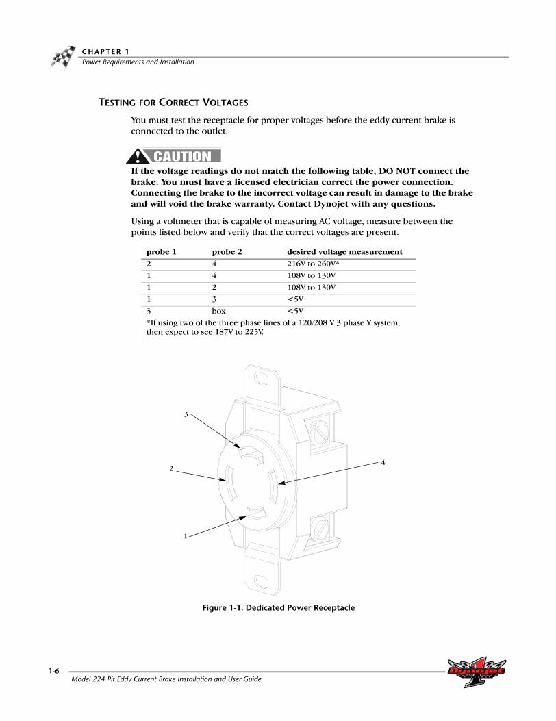
TESTING FOR CORRECT VOLTAGES
You must test the receptacle for proper voltages before the eddy current brake is connected to the outlet.
If the voltage readings do not match the following table, DO NOT connect the brake. You must have a licensed electrician correct the power connection. Connecting the brake to the incorrect voltage can result in damage to the brake and will void the brake warranty. Contact Dynojet with any questions.
Using a voltmeter that is capable of measuring AC voltage, measure between the points listed below and verify that the correct voltages are present.
Figure 1-1: Dedicated Power Receptacle
probe 1 probe 2 desired voltage measurement
2 4 216V to 260V*
1 4 108V to 130V1 2 108V to 130V
1 3 <5V
3 box <5V*If using two of the three phase lines of a 120/208 V 3 phase Y system, then expect to see 187V to 225V.
4
1
2
3
Model 224 Pit Eddy Current Brake Installation and User Guide1-6

E D D Y C U R R E N T B R A K E I N S T A L L A T I O NPower Requirements and Installation
REPLACING THE POWER PLUG
Use the following instructions to replace the four wire plug and socket.
The plug and socket configuration must be rated for at least 240VAC 30A and have a minimum of four conductors.
The power cord that attaches to the brake has four conductors internally and their colors are brown, blue, black, and green/yellow.
1 Connect 240VAC single phase power between the brown and the blue wire connection points.
2 Connect the green/yellow wire to the ground connection point.3 Wrap the black wire with the white tape to denote that it is a neutral connection
and connect it to the neutral connection point.4 Refer to the previous table for testing and probe the new connections as follows:
• blue wire as location #2• brown wire as location #4• black wire as location #1• green/yellow wire as location #3.
HARD WIRING TO THE BUILDING
Use the following instructions to wire the dyno directly to the building.
The brake must connect to a two pole disconnect switch to allow the removal of all power to the dyno for servicing. This box may contain fusing, circuit breakers, or the circuit protection may be upstream in the building power system. The circuit must be protected to 30A with slow blow fuses or time delayed circuit breakers.
The power cord that attaches to the dyno has four conductors internally and their colors are brown, blue, black, and green/yellow.
1 Remove the brake power plug and connect 240VAC single phase between the brown and the blue wires through the disconnect switch.
2 Connect the green/yellow wire to the ground connection. 3 Wrap the black wire with white tape to denote that it is a neutral connection and
connect it to the neutral connection.4 Refer to the previous table for testing and probe the new connections as follows:
• blue wire as location #2• brown wire as location #4• black wire as location #1• green/yellow wire as location #3
Version 2 Model 224 Pit Eddy Current Brake Installation and User Guide1-7

C H A P T E R 1Eddy Current Brake Installation
. . . . . . . . . . . . . . . . . . . . . . . . . . . . . . . . . . .EDDY CURRENT BRAKE INSTALLATION
This section will walk you through removing the eddy current brake from the crate, installing the eddy current brake on model 224 pit automotive dynos, installing the Theta Controller, and routing cables.
You will need to provide equipment capable of lifting the eddy current brake off the crate and into position in your dyno room. You will also need a pair of straps. Dynojet recommends using single loop style straps.
To prevent possible injury, turn off the dyno electronics and unplug the dyno.
BEFORE INSTALLING THE EDDY CURRENT BRAKE: VERIFY OPTIMAL BRAKE COOLING
Placing the eddy current brake on the left or right side of the dyno will determine the direction that it turns.
For optimal eddy current brake cooling, the brake should turn in the direction of the arrows on the rotors.
When running mostly rear wheel drive cars, orient the dyno and brake so the brake is turning in the direction of the arrows when a rear wheel drive car is on the dyno (as shown in Figure 1-2).
Note: The dyno will function correctly for front wheel drive cars, but cooling of the rotors will not be optimal.
The rear wheel drive example below shows the brake turning in the direction of the arrows on the rotors. In this example, the load cell is in compression.
Figure 1-2: Optimal Brake Cooling
arrow on rotor
direction of rotation
load cell
Model 224 Pit Eddy Current Brake Installation and User Guide1-8

E D D Y C U R R E N T B R A K E I N S T A L L A T I O NEddy Current Brake Installation
UNPACKING THE EDDY CURRENT BRAKE
1 Remove the top and sides of the crate.2 Remove any hardware and parts boxes and set aside.3 Remove the uprights and cross members off the crate.
Figure 1-3: Remove the Crate Top
uprights and cross members
crate top
remove boxes
Version 2 Model 224 Pit Eddy Current Brake Installation and User Guide1-9

C H A P T E R 1Eddy Current Brake Installation
4 Remove the two screws securing each pit cover support. Set the screws and covers aside.
#RECORDBe sure you record the dynamometer and/or eddy current brake number on the inside cover of this manual.
Figure 1-4: Remove the Pit Cover Supports
INSTALLING THE BEARING
The eddy current brake can be installed on either side of your dyno, the installation instructions are the same.
1 Install the bearing using two 1/2-13 x 1.25-inch flanged bolts. Leave the bolts loose.Note: If you are retrofitting an early model dyno which does not have the bearing mounting holes, refer to the instructions in Appendix C.
Figure 1-5: Install the Bearing
EB096
pit cover support
pit cover support
brake number
bearing
bearing mounting holes
Model 224 Pit Eddy Current Brake Installation and User Guide1-10

E D D Y C U R R E N T B R A K E I N S T A L L A T I O NEddy Current Brake Installation
INSTALLING THE SPLINE SHAFT AND DRIVELINE ASSEMBLY
1 Insert the spline shaft through the bearing and into the spline hub of drum.Note: Make sure the short spline end faces out.
2 Push the spline shaft as far as it will go.3 Torque the bearing mounting bolts to 57 ft.-lbs.4 Torque the two set screws on the bearing to 25 ft.-lbs.
Figure 1-6: Install the Spline Shaft
5 Remove the four bolts securing the u-joint to the keyed driveline yoke. Set these bolts aside; they will be used to secure the eddy current brake to the driveline assembly.
6 Separate the keyed yoke from the driveline assembly. You may need to use a screwdriver or pry bar to separate the u-joint from the yoke.
7 Place the driveline assembly on the spline shaft.
Figure 1-7: Install the Driveline Assembly
spline shaft
bearing set screws
bearing mounting bolts
driveline assembly
remove four bolts, two on either side
Version 2 Model 224 Pit Eddy Current Brake Installation and User Guide1-11

C H A P T E R 1Eddy Current Brake Installation
INSTALLING THE EDDY CURRENT BRAKE
1 Remove the four lag bolts securing the brake to the crate2 Place the keyed yoke onto the eddy current brake shaft.
Figure 1-8: Remove the Bolts Securing the Brake to the Crate and Install the Yoke
shaft
boltyoke
shaft
Model 224 Pit Eddy Current Brake Installation and User Guide1-12

E D D Y C U R R E N T B R A K E I N S T A L L A T I O NEddy Current Brake Installation
3 Place one nylon loop strap around the brake shaft with the yoke. Keep the strap
close to the bearing.4 Place one nylon loop strap around the other side of the brake shaft. Keep the
strap close to the bearing.
Dynojet recommends using single loop style straps.
5 Place the nylon loop straps around the forklift forks.6 Slide the forklift forks together until the straps angle inward. This will prevent the
straps from slipping off the brake shaft.7 Using the forklift, lift the eddy current brake from the crate and place the brake in
the pit next to the dyno.
Figure 1-9: Remove the Brake from the Crate
shaft
straps
yoke
Version 2 Model 224 Pit Eddy Current Brake Installation and User Guide1-13

C H A P T E R 1Eddy Current Brake Installation
8 Line up the eddy current brake yoke with the driveline assembly.9 Slide the brake frame towards the dyno frame until they touch. Make sure the
brake yoke is aligned with the driveline.10 Secure the yoke to the driveline assembly using the four bolts removed earlier.
Torque the bolts to 70 ft.-lbs.11 Secure the brake frame to the dyno using eight 3/8 x 1-inch bolts and
eight 5/16-inch hardened flat washers. Not all of the bolts and washers are visible from this view.
12 Torque the brake yoke set screws to 25 ft.-lbs.
Figure 1-10: Secure the Brake Frame to the Dyno
bolts and washers (not all visible)
bolts and washers (not all visible)
brake yoke
Model 224 Pit Eddy Current Brake Installation and User Guide1-14

E D D Y C U R R E N T B R A K E I N S T A L L A T I O NEddy Current Brake Installation
INSTALLING THE PIT COVER SUPPORTS AND THETA CONTROLLER
1 Loosely secure the pit cover supports to the frame using two 1/4-20 x 3/4-inch button-head flange screws for each support.Note: Do not tighten the screws.
2 Verify the pit cover supports are flush with the top of the pit floor before you tighten the screws.2a Place a straight edge across the pit cover supports.2b With the pit cover supports tight against the straight edge, tighten the
screws.Note: You can use c-clamps to attach the upright to the straight edges to make this quicker. Tighten the c-clamps until the pit cover supports are flush with the pit floor.
2c Remove the straight edge.
Figure 1-11: Install the Pit Cover Supports
pit cover supports
Version 2 Model 224 Pit Eddy Current Brake Installation and User Guide1-15

C H A P T E R 1Eddy Current Brake Installation
3 Install the Theta Controller using four 8-32 x 3/8-inch screws.4 Install the cable routing channel using two screws.
Figure 1-12: Install the Theta Controller and Cable Routing Channel
cable routing channels
theta controller
Model 224 Pit Eddy Current Brake Installation and User Guide1-16

E D D Y C U R R E N T B R A K E I N S T A L L A T I O NEddy Current Brake Installation
SECURING THE BRAKE TO THE DYNO PIT FLOOR
1 Install one foot on either side of the brake, as shown in Figure 1-13, using one 1/2-13 x 1.25-inch flange bolt and one 1/2-13-inch nylock nut (not visible).
2 Install the Red Head Anchors. Refer to Appendix A for Red Head Anchor installation instructions.
Figure 1-13: Secure the Brake to the Pit Floor
foot
install red head anchor
Version 2 Model 224 Pit Eddy Current Brake Installation and User Guide1-17

C H A P T E R 1Eddy Current Brake Installation
ROUTING THE BRAKE CABLES
Refer to Figure 1-14 on page 1-18 for cable routing location information.
1 Route the temperature sensor cable from the eddy current brake over to the Breakout board.
For more information on wiring the Breakout board refer to page 1-19.
2 Route the speed pick-up cable from the Breakout board over to the pick-up card.3 Route the 25-pin cable from the Breakout board along the inside of the panel
using the cable routing channel, through one of the PVC conduits in the pit, and to the dyno electronics.
4 Route the brake power cable from the eddy current brake through the pit cover support and over to the Theta Controller (underneath).
5 Route the input power cable from the Theta Controller through pit cover support, through the PVC conduit in the pit (not used by any other cables), and to your power source.
6 Route the control cable from the Theta Controller to the Breakout board.
Figure 1-14: Routing the Brake Cables
control cable
temperature sensor cable
brake power cable
input power cable theta controller
breakout board
speed pick-up cable
25-pin cable
Model 224 Pit Eddy Current Brake Installation and User Guide1-18
E D D Y C U R R E N T B R A K E I N S T A L L A T I O NEddy Current Brake Installation
WIRING THE BREAKOUT BOARD
Refer to Figure 1-15 on page 1-20 for Breakout board location information.
1 Attach the temperature sensor cable to the Breakout board. The temperature sensor cable has five wires which connect to the wiring block labeled TEMP. This cable was routed to the Breakout board on page 1-18.
2 Attach the control cable to the Breakout board. The control cable has five wires which connect to the wiring block labeled LOAD CONTROL. This cable was routed to the Breakout board on page 1-18.
3 Attach the speed pick-up cable to the Breakout board. The control cable has four wires which connect to the wiring block labeled DRUM 1. This cable was routed to the Breakout board on page 1-18.
• Green wire connects to G1 • White wire connects to W1
• Black wire connects to B1 • Red wire connects to R1
• Ground (shield) wire connects to S1
• Black wire connects to V- • Red wire connects to V+
• White wire connects to O+ • Green wire connects to O-
• Ground (shield) wire connects to SH
• Red wire connects to R1 • Black wire connects to B1
• White wire connects to W1 • Ground (shield) wire connects to S1
Version 2 Model 224 Pit Eddy Current Brake Installation and User Guide1-19
C H A P T E R 1Eddy Current Brake Installation
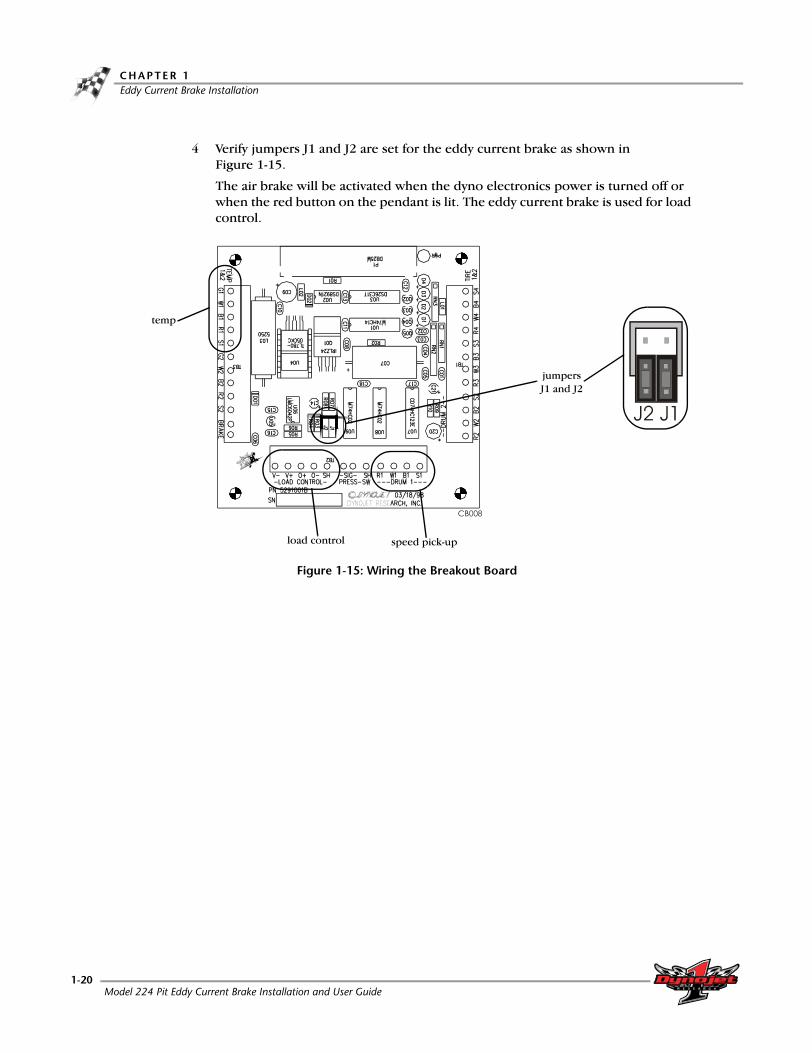
4 Verify jumpers J1 and J2 are set for the eddy current brake as shown in Figure 1-15.
The air brake will be activated when the dyno electronics power is turned off or when the red button on the pendant is lit. The eddy current brake is used for load control.
Figure 1-15: Wiring the Breakout Board
jumpers J1 and J2
load control
temp
speed pick-up
Model 224 Pit Eddy Current Brake Installation and User Guide1-20
E D D Y C U R R E N T B R A K E I N S T A L L A T I O NEddy Current Brake Installation
REPLACING THE THETA CONTROLLER FUSES
Hazardous voltage. To avoid risk of electrical shock, disconnect the battery and unplug the dyno.
1 Remove the nine button-head screws securing the deck assembly and set aside.2 Remove the deck assembly and set aside.3 Gently push the fuse holder slightly inward and rotate counterclockwise. Remove
the fuse holder.4 Replace the fuse with a fuse type listed below.
For continued protection against risk of fire, replace only with a fuse of the same type and having the same electrical rating.
• Buss P/N BAF-25, 25A Fuse• Fast Blow, Dynojet P/N 54212501
5 Replace the deck assembly using the nine button-head screws removed earlier. Refer to Figure 2-10 on page 2-10.
Version 2 Model 224 Pit Eddy Current Brake Installation and User Guide1-21


C H A P T E R
2TORQUE MODULE INSTALLATION
The Torque Module, when added to Dynojet's market leading inertia dynamometer, results in a complete vehicle performance test.
This chapter provides instructions for installing and using the Torque Module with WinPEP 7. To ensure safety and accuracy in the procedures, perform the procedures as they are described.
This chapter is divided into the following categories:
• Load Cell Installation, page 2-2
• Torque Module Installation, page 2-4
• Load Cell Calibration, page 2-11
Model 224 Pit Eddy Current Brake Installation and User Guide2-1

C H A P T E R 2Load Cell Installation
. . . . . . . . . . . . . . . . . . . . . . . . . . . . . . . . . . .LOAD CELL INSTALLATION
This section describes how to install the load cell.
PARTS LIST
The following table lists all of the parts included in the Torque Module Installation kit (P/N 73920007). Check your kit against the parts listed to make sure you have received all of the parts. If any part is missing, contact Dynojet Technical Support.
INSTALLING THE LOAD CELL
1 Verify the main dyno power is disconnected.2 Remove the two bolts and nuts securing the existing bar on the eddy current
brake and remove the bar. Set the bolts and nuts aside.3 Verify the eyelets on the load cell are spaced the same as the bar removed earlier.
Adjust the load cell spacing by loosening the lock nut and turning the eyelet.
Figure 2-1: Verify Load Cell Spacing
part number description quantity
35430899 Weight, 25 lb 4
61319001 Calibration Arm Assembly 1
66114002or66104001
Torque Module Sub-AssemblyorTorque Module High Resolution Sub-Assembly
1
76950505 Torque Cell Assembly, 224 1
76950606 Cable, Input, 224 Torque Rev Sw 1
76950607 Cable, Output, 224 Torque Rev Sw 1
distance must be the same
eyeletbar
lock nut
Model 224 Pit Eddy Current Brake Installation and User Guide2-2

TO R Q U E M O D U L E I N S T A L L A T I O NLoad Cell Installation
4 Secure the load cell to the mounting bracket using the two bolts and nuts
removed earlier.5 Route the load cell cable through the PVC conduit in the pit (not used by the
input power cable). Make sure the load cell cable is clear of any power cable or hot or rotating objects.
Figure 2-2: Install the Load Cell
install the load cell(the brake is not shown for clarity)
load cell cable
dyno
Version 2 Model 224 Pit Eddy Current Brake Installation and User Guide2-3

C H A P T E R 2Torque Module Installation
. . . . . . . . . . . . . . . . . . . . . . . . . . . . . . . . . . .TORQUE MODULE INSTALLATION
This section describes how to access the dyno electronics, install the Torque Module, route the load cell cable, and install the side and top brake covers.
ACCESSING THE DYNO ELECTRONICS
You will need to access your dyno electronics in order to add the torque module. Use the following steps to access the dyno electronics.
1 Remove the eight screws securing the cover and lift the cover off.2 Add the torque module to the top of the dyno electronics. Refer to “Installing the
Torque Module” on page 2-5.3 Leave the dyno electronics enclosure out. You will need to route the load cell
cable to the Torque Module later.
Figure 2-3: Inside the Electronics Enclosure
dyno electronics
Model 224 Pit Eddy Current Brake Installation and User Guide2-4

TO R Q U E M O D U L E I N S T A L L A T I O NTorque Module Installation
2-5
INSTALLING THE TORQUE MODULE
1 Verify the main dyno power is disconnected.2 Turn off the main power switch on the CPU Module on the dyno electronics and
unplug the power cord.3 Remove the dust cover from the existing top module.
Figure 2-4: Remove Dust Cover
4 Loosen the top right screw on the back of the existing top module.5 Plug the Torque Module into the existing top module. Place the dust cover,
removed in step 3, on the Torque Module.6 Secure the grounding strap on the back of the Torque Module to the existing top
module.
Figure 2-5: Secure Grounding Strap
dust cover
power cord input
power switch
grounding strap
Version 2 Model 224 Pit Eddy Current Brake Installation and User Guide

C H A P T E R 2Torque Module Installation
7 Secure the Torque Module to the dyno electronics with the plastic tie straps (one on each side).Note: Do not attach the load cell cable at this time.
Figure 2-6: Attach Torque Module
load cell cable and portdo not attach at this time
green LED lighttie strap
torque module
Model 224 Pit Eddy Current Brake Installation and User Guide2-6
TO R Q U E M O D U L E I N S T A L L A T I O NTorque Module Installation
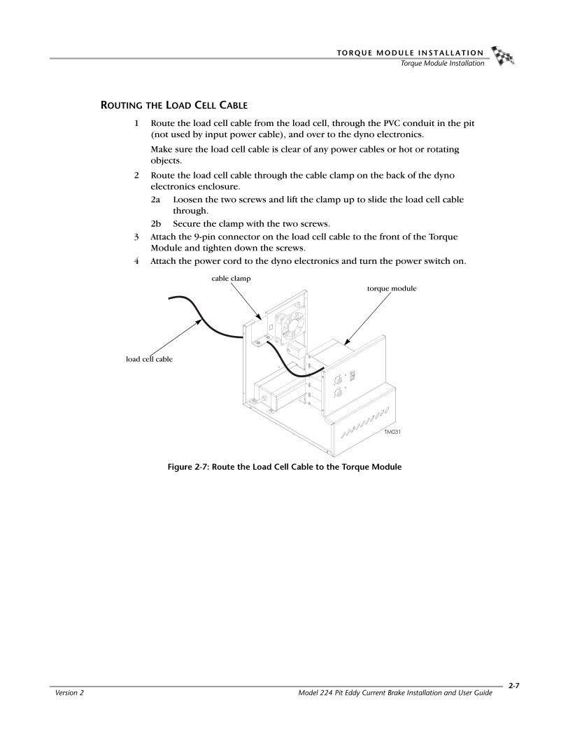
ROUTING THE LOAD CELL CABLE
1 Route the load cell cable from the load cell, through the PVC conduit in the pit (not used by input power cable), and over to the dyno electronics.
Make sure the load cell cable is clear of any power cables or hot or rotating objects.
2 Route the load cell cable through the cable clamp on the back of the dyno electronics enclosure.2a Loosen the two screws and lift the clamp up to slide the load cell cable
through.2b Secure the clamp with the two screws.
3 Attach the 9-pin connector on the load cell cable to the front of the Torque Module and tighten down the screws.
4 Attach the power cord to the dyno electronics and turn the power switch on.
Figure 2-7: Route the Load Cell Cable to the Torque Module
torque modulecable clamp
load cell cable
Version 2 Model 224 Pit Eddy Current Brake Installation and User Guide2-7

C H A P T E R 2Torque Module Installation
5 The green LED light on the Torque Module should now be on.6 Replace the dyno electronics cover.
Figure 2-8: Attach Torque Module and Load Cell Cable
load cell cable and portdo not attach at this time
green LED lighttie strap
torque module
Model 224 Pit Eddy Current Brake Installation and User Guide2-8

TO R Q U E M O D U L E I N S T A L L A T I O NTorque Module Installation
INSTALLING THE END DECK AND DECK ASSEMBLIES
1 If not already installed, secure the hood scoops to the covers using fourbutton-head screws and nuts per hood scoop.
2 Install the end deck assembly using five 3/8-16 x 1-inch button-head flange screws.
Figure 2-9: Install the End Deck Assembly
end deck assembly
hood scoops
Version 2 Model 224 Pit Eddy Current Brake Installation and User Guide2-9

C H A P T E R 2Torque Module Installation
3 Install the deck assembly using nine 3/8-16 x 1-inch button-head flange screws.
Figure 2-10: Install the Deck Assembly
deck assembly
hood scoop
Model 224 Pit Eddy Current Brake Installation and User Guide2-10

TO R Q U E M O D U L E I N S T A L L A T I O NLoad Cell Calibration
. . . . . . . . . . . . . . . . . . . . . . . . . . . . . . . . . . .LOAD CELL CALIBRATION
This section provides instructions for using the Torque Module with WinPEP 7. The Torque Module must be calibrated prior to use. Follow the directions on the screen exactly. Failure to perform the directions accurately will result in improper torque values.
1 Verify you are in the MakeRun screen.2 Verify you are connected to the dyno electronics.
Note: For more information on connecting to the dyno electronics, refer to the WinPEP 7 User Guide (on your WinPEP CD or at www.dynojet.com/manuals.shtml) or the WinPEP 7 Online Help.
3 Select Tools MakeRun Options Torque Cell Calibration.Note: Before proceeding, be sure the eddy current brake is free and clear of any obstructions. There should not be anything resting on the eddy current brake or the dynamometer drum during this procedure.
4 Click Next to perform the Zero Calibration.
The Calibration window will appear. The hardware is now zeroing out the torque cell. If the unit does not calibrate, recheck the setup and retry.
Figure 2-11: Zero Calibration Window
Version 2 Model 224 Pit Eddy Current Brake Installation and User Guide2-11

C H A P T E R 2Load Cell Calibration
Once the Zero Calibration is complete, the Calibration Mass window will appear.
5 Enter the Torque Module calibration value. Refer to Figure 2-13.Note: You must perform this step the first time you calibrate the load cell.
Or
If you are only performing a Zero Calibration, click Finish.
Figure 2-12: Calibration Mass Window
Enter the calibration number stamped near the bolt pattern at the end of the calibration arm. If you do not have enough room to use the bolt pattern closest to the end of the calibration arm, use the number stamped near the bolt pattern in the center of the arm.
Note: Dynojet recommends you secure the calibration arm using the bolt pattern closest to the end of the arm unless space constraints in your dyno room do not allow you to.
Figure 2-13: Calibration Arm Number
bolt pattern closest to the end of the calibration arm
bolt pattern near the center of the
calibration arm
Model 224 Pit Eddy Current Brake Installation and User Guide2-12
TO R Q U E M O D U L E I N S T A L L A T I O NLoad Cell Calibration
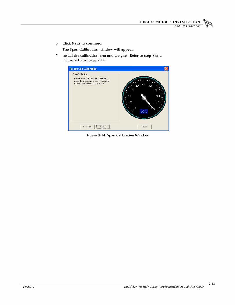
6 Click Next to continue.
The Span Calibration window will appear.
7 Install the calibration arm and weights. Refer to step 8 and Figure 2-15 on page 2-14.
Figure 2-14: Span Calibration Window
Version 2 Model 224 Pit Eddy Current Brake Installation and User Guide2-13

C H A P T E R 2Load Cell Calibration
8 Install the calibration arm and weights using the bolts at the end of the calibration arm.Note: If you do not have enough room to use the bolt pattern closest to the end of the calibration arm, use the bolt pattern in the center of the arm. Refer to Figure 2-16 on page 2-15.
8a Secure the calibration arm to the eddy current brake by tightening the bolt using the handle.
8b Gently place the weights on the calibration arm.Note: Verify the calibration arm is not contacting the cover.
The calibration weights are very heavy. The weights must be set on the arm gently or you will damage the load cell.
Figure 2-15: Install Calibration Arm and Weights Using the Bolt Pattern Closest to the End
weights
weight support pin
secure arm to brake by tightening handle
Model 224 Pit Eddy Current Brake Installation and User Guide2-14

TO R Q U E M O D U L E I N S T A L L A T I O NLoad Cell Calibration
If you do not have enough room to use the bolt pattern closest to the end of the calibration arm, use the bolt pattern in the center of the arm as shown in Figure 2-16.
Figure 2-16: Install Calibration Arm and Weights Using the Bolt Pattern in the Center
weights
weight support pin
secure arm to brake by tightening handle
Version 2 Model 224 Pit Eddy Current Brake Installation and User Guide2-15
C H A P T E R 2Load Cell Calibration
While installing the calibration weights, you should notice the Torque Gauge on the DynoTrac Window moving from 0 to about 500 foot-pounds.
Note: The Torque Gauge may or may not be in this range.
• If the torque cell has been previously calibrated incorrectly or has not been calibrated for a while, the gauge may show values out of this range until calibration is complete.
• If you use the bolt pattern in the center of the calibration arm, the gauge will show values around 250-260 foot-pounds.
Note: Let the torque gauge needle stabilize before clicking Next.
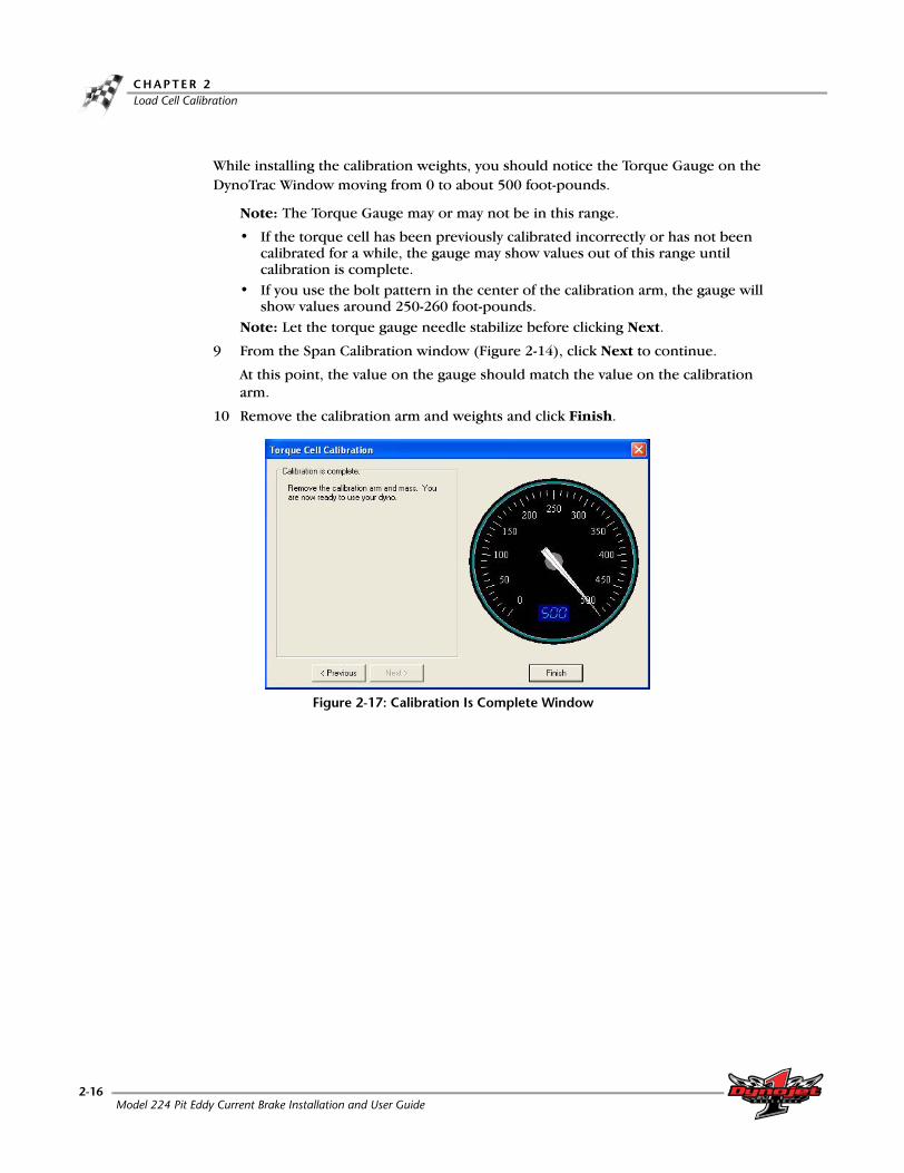
9 From the Span Calibration window (Figure 2-14), click Next to continue.
At this point, the value on the gauge should match the value on the calibration arm.
10 Remove the calibration arm and weights and click Finish.
Figure 2-17: Calibration Is Complete Window
Model 224 Pit Eddy Current Brake Installation and User Guide2-16

C H A P T E R
3BASIC DYNAMOMETER OPERATION
The Dynojet dynamometer (dyno) gives state of the art technology, durability, and accuracy that you need. Dynojet’s advanced engineering delivers the precise horsepower measurements a technician needs to make quick and accurate evaluations of engine performance and drive train problems.
This chapter will walk you through loading and preparing your dynamometer and includes instructions for basic dyno operation. For more detailed instructions, refer to the WinPEP 7 User Guide. This manual can be found on your WinPEP CD or at www.dynojet.com/manuals.shtml.
This chapter is divided into the following categories:
• Loading the Car, page 3-2
• Connecting the RPM Pickup, page 3-5
• Pre-Run Inspection, page 3-8
• Making a Run, page 3-10
Model 224 Pit Eddy Current Brake Installation and User Guide3-1

C H A P T E R 3Loading the Car
. . . . . . . . . . . . . . . . . . . . . . . . . . . . . . . . . . .LOADING THE CAR
Use the following steps to load a car on the dyno.
1 Verify the dyno electronics power is on and connected to your computer.2 Make sure you are in the MakeRun screen.3 Set the dyno brake on by pressing the red button on the hand held pendant.4 For four or all wheel drive vehicles, measure the wheel base on the vehicle and
adjust the 224-4WD dyno to the dimension before driving the vehicle on the dyno.
5 Drive the vehicle onto the dyno and align the vehicle straight with the dyno.6 Stop the vehicle when the drive axle(s) is centered on the drum(s).
Figure 3-1: Center the Drive Axle(s) on the Drum(s)
7 When the vehicle is positioned properly on the dyno, shut the engine off.• If the vehicle has an automatic transmission, place it in park.• If the vehicle has a manual transmission, place it in gear.
8 Set the vehicle’s emergency brake.9 Secure the non-drive wheels using the provided tire chocks. Do not use tire
chocks for four wheel drive vehicles.
center drive axle on dyno drum
adjust wheel base of 224-4wd dyno
center drive axle on both dyno drums
rear or front wheel drive vehicles
four or all wheel drive vehicles
Model 224 Pit Eddy Current Brake Installation and User Guide3-2

B A S I C D Y N A M O M E T E R O P E R A T I O NLoading the Car
10 Attach the tie-down straps.
Rear Wheel Drive
• Attach two tie-down straps from secure anchor points to the rear of the vehicle. Attach additional tie-down straps from the rear of the vehicle as shown in Figure 3-2.
• Attach two tie-down straps from secure anchor points to the front of the vehicle.
Front Wheel Drive
• Attach two tie-down straps from secure anchor points to the rear of the vehicle.
• Attach two tie-down straps from secure anchor points to the front of the vehicle. Attach additional tie-down straps across the front of the vehicle to form a crisscross.
Four Wheel (All Wheel) Drive
• Attach two tie-down straps from secure anchor points to the rear of the vehicle. If the vehicle is equipped with a rear steering system, attach additional tie-down straps across the rear of the vehicle to form a crisscross.
• Attach two tie-down straps from secure anchor points to the front of the vehicle. Attach additional tie-down straps across the front of the vehicle to form a crisscross.
Figure 3-2: Attach Tie-down Straps
rear wheel drive front wheel drive four wheel drive
Version 2 Model 224 Pit Eddy Current Brake Installation and User Guide3-3
C H A P T E R 3Loading the Car
11 Tighten the tie-down straps evenly making sure that the drive wheels remain centered on the drum.
The tie-down straps should always be connected to the vehicle’s solid axle or the suspension control arms. Factory tie-down hooks connected to the vehicle’s frame may be used on the end opposite the drive wheels (for example: the front end of a rear driven vehicle).
12 Release the brake on the vehicle and the dyno.13 Start the vehicle and put the transmission into first gear or drive.14 Press the accelerator pedal so the drums begin turning slowly. While the drums
are slowly turning, get a feel for the stability of the vehicle. Stop the drum with the dyno brakes.
15 Check all the straps and ensure the vehicle is tracking straight on the dyno.
Model 224 Pit Eddy Current Brake Installation and User Guide3-4

B A S I C D Y N A M O M E T E R O P E R A T I O NConnecting The RPM Pickup
. . . . . . . . . . . . . . . . . . . . . . . . . . . . . . . . . . .CONNECTING THE RPM PICKUP
Your Dynojet dynamometer includes a primary wire inductive pickup and two secondary wire inductive pickups. These small “clothespin like” inductive pickups are used to sense RPM. An RPM pickup is required if you want to view torque graphs. Generally you will use one secondary wire inductive pickup on a spark plug wire. Vehicles with wasted spark ignition systems may require two secondary inductive pickups. On a wasted spark ignition, typically one coil will be connected to two spark plug wires. Attach one secondary pickup to each of these wires. If the pickups are connected to two plug wires that do not fire at the same time, an erratic RPM readout may occur. The primary wire inductive pickup senses RPM pulses from the coil. Although this pickup location generally works better, it is harder to find the correct location to connect the RPM pickup.
Note: If a pickup is not being used, disconnect it from the dyno electronics to prevent any stray pick up of signals.
The optional Optical Sensor is useful on diesel powered vehicles, MSD ignitions, and other high RFI ignition systems. For more detailed information on the Optical Sensor, refer to the Optical RPM Sensor Installation Guide (P/N 98295109).
Inductive pickups are very fragile. The ferrite core can easily be damaged and is not covered under warranty. Dropping, snapping, vibration, and heat can all damage the ferrite core.
The DynoWare EX+ RPM module contains the electronics that sense the RPM pulses. An auto-gain circuit looks at only the peak voltage of the vehicle’s spark, ignoring the lower voltages to help reduce electronic noise problems. Wasted spark ignition systems will produce a lower voltage level on the exhaust stroke than the compression stroke. By definition of the auto-gain circuit, lower voltage spark levels will be ignored, missing every other spark the vehicle would produce.
RPM PICKUP DESCRIPTIONS
RPM pickup description
Secondaries (Non- wasted spark system) Use one secondary pickup. Unplug the other pickup from the RPM module and set the degrees between plug fires to 720° in WinPEP.
Secondaries (Wasted spark ignition system)
Use two secondary pickups. Attach one pickup on each spark plug wire on the same coil and set the degrees between plug fires to 360° in WinPEP.
Primary pickup Attach the primary wire pickup to the primary side of the coil. Set the degrees between plug fires by taking 720/number of cylinders. For example, the number of degrees between plug fires on a V-8 engine with a single coil is 720/8=90 degrees.
Optional Optical RPM Sensor Attach the sensor wire to the RPM module, also be sure to plug in the small power lead into the CPU module. The other end of the wire attaches to the Optical Sensor. Set the degrees between plug fires to 360° in WinPEP. Refer to the Optical RPM Sensor Installation Guide (P/N 98295109).
Version 2 Model 224 Pit Eddy Current Brake Installation and User Guide3-5
C H A P T E R 3Connecting The RPM Pickup
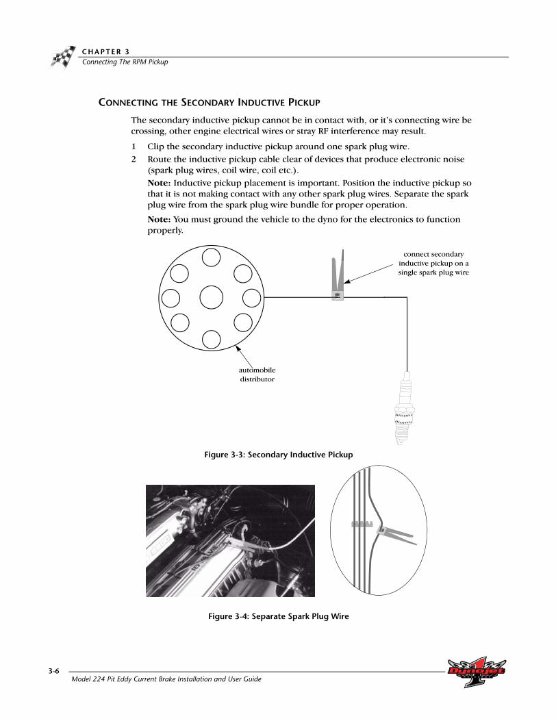
CONNECTING THE SECONDARY INDUCTIVE PICKUP
The secondary inductive pickup cannot be in contact with, or it’s connecting wire be crossing, other engine electrical wires or stray RF interference may result.
1 Clip the secondary inductive pickup around one spark plug wire.2 Route the inductive pickup cable clear of devices that produce electronic noise
(spark plug wires, coil wire, coil etc.).Note: Inductive pickup placement is important. Position the inductive pickup so that it is not making contact with any other spark plug wires. Separate the spark plug wire from the spark plug wire bundle for proper operation.
Note: You must ground the vehicle to the dyno for the electronics to function properly.
Figure 3-3: Secondary Inductive Pickup
Figure 3-4: Separate Spark Plug Wire
connect secondary inductive pickup on a single spark plug wire
automobile distributor
Model 224 Pit Eddy Current Brake Installation and User Guide3-6

B A S I C D Y N A M O M E T E R O P E R A T I O NConnecting The RPM Pickup
CONNECTING THE PRIMARY INDUCTIVE PICKUP
The primary inductive pickup cannot be in contact with, or it’s connecting wire be crossing, other engine electrical wires or stray RF interference may result.
1 Clip the primary inductive pickup around the primary side of the coil.2 Route the primary wire cable clear of devices that produce electronic noise.
Note: You must ground the vehicle to the dyno for the electronics to function properly.
Figure 3-5: Primary Inductive Pickup
connect primary inductive pickup on the negative side of the coil
coil
Version 2 Model 224 Pit Eddy Current Brake Installation and User Guide3-7

C H A P T E R 3Pre-run Inspection
. . . . . . . . . . . . . . . . . . . . . . . . . . . . . . . . . . .PRE-RUN INSPECTION
Perform a vehicle inspection before making a run.
• Check the radiator coolant and oil levels.
• Check the fuel source.
• Rotate the drum(s) and check for rocks caught in the tire tread that could fly out.
• Check the tire pressure and tire speed rating. Improperly inflated tires or exceeding the maximum speed rating can result in premature wear or severe tire damage. Make sure the tire has no major deficiencies (cracks in sidewalls, tread life, etc.).
• Visually inspect the vehicle. Make sure it is in safe running order.
• Make sure ear protection and safety glasses are used when the dyno is being operated.
• Check the tie-down straps to make sure that they are tight and secured.
• Check the drive tires to be sure that they are aligned correctly on the dynamometer’s drums.
• Keep all rotating components clear at all times.
• Only the operator should be near the dyno or the vehicle during the test.
• Never allow any person(s) to stand behind the dyno or vehicle when it is being operated.
• Perform any other safety inspections appropriate to running your vehicle on the dyno.
Never allow any person(s) to stand behind the dyno or vehicle when it is being operated. Only the operator should be near the dyno or the vehicle during the test.
BEFORE STARTING THE ENGINE
Connect an exhaust hose or hoses (if dual exhaust) on the vehicle, make sure the hose fits over the tail pipe, is not plugged or kinked and the hose is vented correctly out of the dyno room.
Engine exhaust contains poisonous carbon monoxide gas. Breathing id could cause death. Operate machine in well ventilated area.
Model 224 Pit Eddy Current Brake Installation and User Guide3-8

B A S I C D Y N A M O M E T E R O P E R A T I O NPre-run Inspection
ENGINE WARM UP
Warm the vehicle’s engine and drivetrain before beginning testing. Consistent engine temperatures will assure your runs are repeatable.
AFTER ENGINE WARM UP
Always leave the vehicle in park (automatic transmission) or in first gear (manual transmission), with the engine off, and make sure the emergency brake and the dyno brake are on when you get out of the vehicle.
• Fix any fuel, oil, or coolant leaks that may have shown up after engine warm up and check the carburetor for leaks.
• Any loud or unusual engine noises or excessive exhaust smoke should be resolved before continuing.
Version 2 Model 224 Pit Eddy Current Brake Installation and User Guide3-9

C H A P T E R 3Making a Test Run
. . . . . . . . . . . . . . . . . . . . . . . . . . . . . . . . . . .MAKING A TEST RUN
Dyno runs provide safe, reliable road testing right in the shop. The dyno allows you to measure, record, and diagnose performance problems quickly. The dyno combined with WinPEP 7 produces consistent, easily interpretable power graphs. Use the following instructions to ensure repeatable and accurate measurements.
1 Verify the vehicle is secured properly.2 Place the vehicle in a low gear and release the dyno brake using the hand held
pendant.3 Slowly accelerate the vehicle to 20 m.p.h.4 Test the tachometer operation.
4a Rev the engine. The gauges on the computer screen should be moving. If the tachometer is moving but not registering the correct RPM values, the number of degrees of revolution of the crank shaft (the plug fires number) is incorrect.
4b Stop the vehicle, return to the MakeRun Configuration dialog box, and enter the correct value for the plug firing order.
5 Press the red brake button to apply 100% braking and slow down the vehicle.
Using the vehicle’s own brakes to slow or stop the drum at speeds over 30 m.p.h. can severely over heat the brake parts. Dynojet dynamometers with the mechanical brake, air brake, or eddy current brake accessory can be used to slow the vehicle and drum to a full stop at any speed. The vehicle’s brakes should be used in an emergency stop situation only.
6 Shut the engine off and put the vehicle in gear (manual transmission) or park (automatic transmission).
7 Set the vehicle’s parking brake and leave the dyno brake on.8 Perform a final inspection.
• Verify the drive tire’s alignment on the dyno drums.• Make any adjustments to the tie-down straps as needed.• Perform any other safety checks that you deem appropriate to your particular
situation.You are now ready to make a high speed run on the dyno. Refer to your WinPEP 7 User Guide for more detailed instructions.
Model 224 Pit Eddy Current Brake Installation and User Guide3-10

A P P E N D I X
ARED HEAD ANCHOR INSTALLATION
This appendix contains instructions for installing the Red Head Multi-Set™II Anchors. The anchors will be used to secure the dyno to concrete. To ensure safety and accuracy in the procedures, perform the procedures as they are described. Be sure to read and understand the warnings included in this appendix.
WARNINGS
Always wear safety glasses and other necessary protective devices or apparel when installing or working with anchors.
ITW Ramset/Red Head Multi-Set II Anchors are designed to operate properly only when installed with ITW Ramset/Red Head brand Setting Tools.
The use of a 24 to 40 ounce hammer is recommended for expanding Multi-Set II anchors.
The use of carbide drill bits manufactured with ANSI B94. 12-77 drill bit diameter requirements is recommended for installation of this anchor.
Not recommended for use in lightweight masonry material such as block or brick.
Use of core drills is not recommended to drill holes for use with this anchor.
Not recommended for use in new concrete which has not had sufficient time to cure.
Anchor spacing and edge distance requirements (anchor installation locations) are the responsibility of the engineer of record.
CONTACT INFORMATION FOR ITW RAMSET/RED HEADContact ITW Ramset/Red Head at 1-630-350-0370, or 1300 North Michael Drive, Wood Dale, IL 60191.
Model 224 Pit Eddy Current Brake Installation and User GuideA-1

A P P E N D I X AInstallation
. . . . . . . . . . . . . . . . . . . . . . . . . . . . . . . . . . .INSTALLATION
Use the table below to determine the catalog number, drill bit size, minimum hole depth, and setting tool catalog number.
Use the following instructions to install the Red Head anchors.
1 Drill the hole in the concrete the same outside diameter as the anchor being used to any depth exceeding minimum embedment.
Figure A-1: Red Head Anchor—Drill the Hole
2 Insert the anchor.
Figure A-2: Red Head Anchor—Insert the Anchor
catalog number drill bit size minimum hole depthsetting tool catalog number
Carbon SteelRM-38/RL-38 (9.5 mm)
1/2-inch 1 5/8-inch (41.2 mm) RT-138
anchor
Model 224 Pit Eddy Current Brake Installation and User GuideA-2

R E D H E A D A N C H O R I N S T A L L A T I O NInstallation
3 Using a hammer, drive the anchor flush with the surface of the concrete, or below
the surface if the hole depth exceeds minimum embedment.
Figure A-3: Red Head Anchor—Drive the Anchor Flush
4 Using a hammer, expand the anchor with the setting tool. The anchor is properly expanded when the shoulder of the setting tool is flush with the top of the anchor.Note: Use only Ramset/Red Head setting tools to insure proper installtion.
Figure A-4: Red Head Anchor—Expand the Anchor
setting tool
Version 2 Model 224 Pit Eddy Current Brake Installation and User GuideA-3


A P P E N D I X
BPOWER REQUIREMENTS—EXCLUDING
NORTH AMERICA
This appendix contains the power requirements and instructions for all locations excluding North America brake installations. Refer to page 1-5 for power requirements and instructions for North America and Japan. To ensure safety and accuracy in the procedures, perform the procedures as they are described.
Model 224 Pit Eddy Current Brake Installation and User GuideB-1

A P P E N D I X BPower Requirements and Installation
. . . . . . . . . . . . . . . . . . . . . . . . . . . . . . . . . . .POWER REQUIREMENTS AND INSTALLATION
The eddy current brake (excluding North America and Japan) requires a dedicated wall receptacle which must be wired for operation and is included with the brake or may be shipped in advanced in a separate package.
The eddy current brake requires a dedicated 240VAC single phase power outlet rated for 30A for proper operation. Failure to follow these instructions could result in personal injury or damage to the brake. Connecting the brake to the incorrect voltage will void the brake warranty. Contact Dynojet with any questions.
The dedicated wall receptacle is a three-pin IEC grounded 30A type and must be wired in accordance with local building codes and requirements. Installation may require a licensed electrician to conform to applicable safety standards.
If you are installing your brake in a location other than North America or Japan and the brake is not equipped with a three pin IEC grounded plug, contact Dynojet before attempting to connect the brake.
Local and national electrical codes will require that the box containing the receptacle is grounded.
• This circuit should have a dedicated 30A double pole circuit breaker.• The brake should be the only device connected to this circuit.
Model 224 Pit Eddy Current Brake Installation and User GuideB-2

P O W E R R E Q U I R E M E N T S — E X C L U D I N G N O R T H A M E R I C APower Requirements and Installation
INSTALLING THE WALL RECEPTACLE
The wall receptacle is a single 240 volt 30A dedicated circuit with a ground.
The cable carrying the power to this receptacle should be 4.0 mm2 (ten gauge) or larger. Check with local building codes for the correct size.
1 Connect one of the 240V legs to the N terminal (white).2 Connect the other 240V leg to the L terminal (no color).3 Connect the ground conductor to the green terminal.
Figure B-1: Wiring the Wall Receptacle
N terminal (white)
L terminal
ground terminal (green)
Version 2 Model 224 Pit Eddy Current Brake Installation and User GuideB-3
A P P E N D I X BPower Requirements and Installation
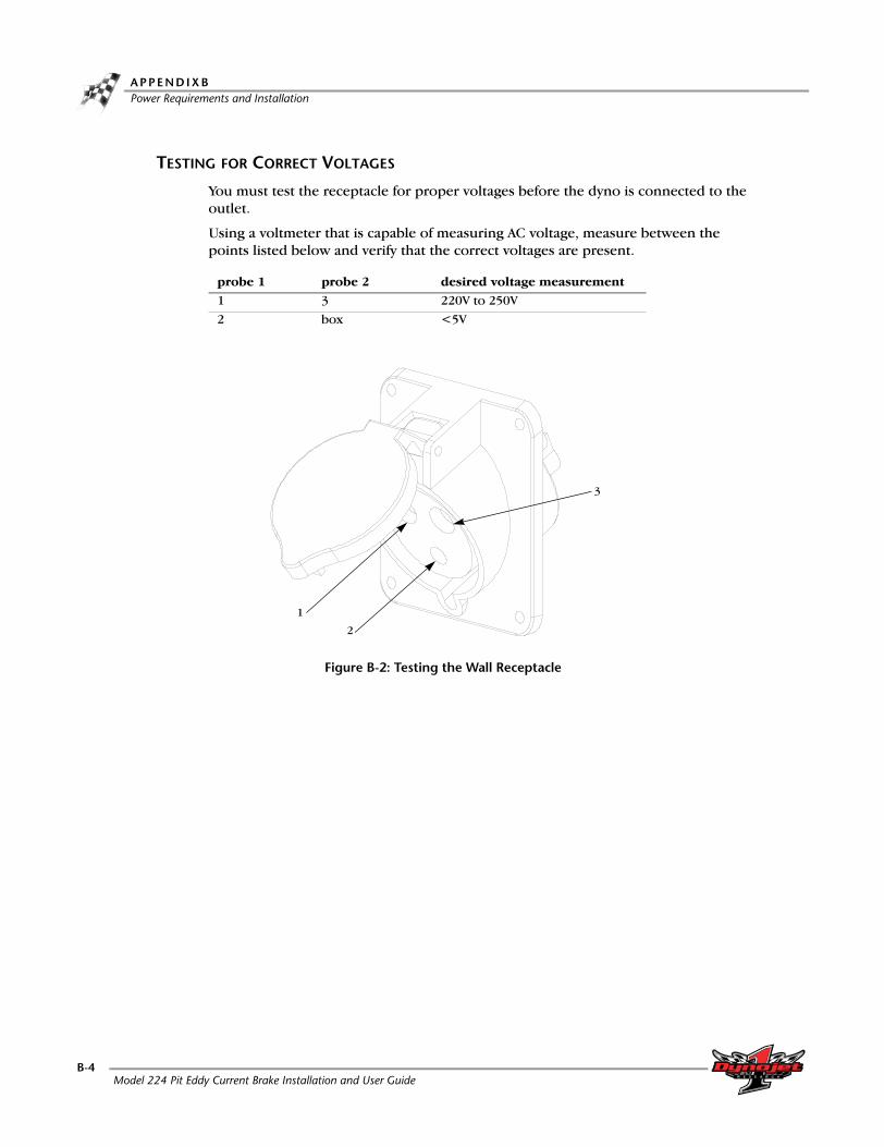
TESTING FOR CORRECT VOLTAGES
You must test the receptacle for proper voltages before the dyno is connected to the outlet.
Using a voltmeter that is capable of measuring AC voltage, measure between the points listed below and verify that the correct voltages are present.
Figure B-2: Testing the Wall Receptacle
probe 1 probe 2 desired voltage measurement
1 3 220V to 250V
2 box <5V
1
2
3
Model 224 Pit Eddy Current Brake Installation and User GuideB-4

P O W E R R E Q U I R E M E N T S — E X C L U D I N G N O R T H A M E R I C APower Requirements and Installation
REPLACING THE POWER PLUG
Use the following instructions to replace the plug and socket.
The plug and socket configuration must be rated for at least 240VAC 30A and have a minimum of three conductors.
The power cord that attaches to the dyno has four conductors internally and their colors are brown, blue, black, and green/yellow.
1 Connect 240VAC single phase power between the brown and the blue wire connection points.
2 Connect the green/yellow wire to the ground connection point.3 Cut off the black wire.4 Refer to the previous table for testing and probe the new connections as follows:
• blue wire as location #1• brown wire as location #3• green/yellow wire as location #2
HARD WIRING TO THE BUILDING
Use the following instructions to wire the brake directly to the building.
The brake must connect to a two pole disconnect switch to allow the removal of all power to the brake for servicing. This box may contain fusing, circuit breakers, or the circuit protection may be upstream in the building power system. The circuit must be protected to 30A with slow blow fuses or time delayed circuit breakers.
The power cord that attaches to the brake has four conductors internally and their colors are brown, blue, black, and green/yellow.
1 Remove the brake power plug and connect 240VAC single phase between the brown and the blue wires through the disconnect switch.
2 Connect the green/yellow wire to the ground connection. 3 Cut off the black wire.4 Refer to the previous table for testing and probe the new connections as follows:
• blue wire as location #1• brown wire as location #3• green/yellow wire as location #2
Version 2 Model 224 Pit Eddy Current Brake Installation and User GuideB-5


A P P E N D I X
CINSTALLING THE ADAPTER AND BEARING—
EARLY MODEL DYNAMOMETERS
This appendix contains instructions for installing the adapter and bearing on early model dynamometers (dynos); this includes dynos with serial numbers between 2240088 and 2240120. To ensure safety and accuracy in the procedures, perform the procedures as they are described.
Model 224 Pit Eddy Current Brake Installation and User GuideC-1

A P P E N D I X CInstalling the Adapter and Bearing—Early Model Dynos
. . . . . . . . . . . . . . . . . . . . . . . . . . . . . . . . . . .INSTALLING THE ADAPTER AND BEARING—EARLY MODEL DYNOS
Dynos missing the bearing mounting holes, shown in Figure 1-5 on page 1-10, will need to use the adapter (P/N 79110001) to install the bearing. This includes dynos with serial numbers between 2240088 and 2240120.
1 Orient the bearing to the adapter as shown in Figure C-1. The arrow on the adapter plate must point up.
2 Secure the bearing to the adapter plate using two 1/2-13 x 1.25-inch flange bolts and two 1/2-13-inch nuts. Leave the bolts loose.Note: The bolts are included with the eddy current brake while the nuts are included with the adapter kit.
Figure C-1: Early Model Dynos—Install Bearing to Adapter
3 Secure the adapter plate to the dyno using six 1/2-13 x 3/4-inch bolts.
Figure C-2: Early Model Dynos—Install Adapter Plate
bearing
adapter plate
arrow
bolt
adapter plate
Model 224 Pit Eddy Current Brake Installation and User GuideC-2

I N S T A L L I N G T H E A D A P T E R A N D B E A R I N G — E A R L Y M O D E L D Y N A M O M E T E R SInstalling the Adapter and Bearing—Early Model Dynos
4 Using the template included in this appendix, drill four additional holes into the
dyno frame as shown.Note: If you needed to use the adapter plate, you will need to drill brake mounting holes in the dyno frame.
4a Line the template up with the existing hole on the dyno.4b Drill two 3/8-16-inch UNC holes on each side of the dyno.
Figure C-3: Early Model Dynos—Using the Template
template
drill holes
existing hole
template
drill holes
existing hole
Version 2 Model 224 Pit Eddy Current Brake Installation and User GuideC-3


5 3/4" 5 3/4"
ø 5/16"
EXISTING HOLE
UP
1 5/8"
5 3/4"
5 3/4"
ADD 3/8-16 UNC HOLES
ADD 3/8-16 UNC HOLES
EXISTING HOLESEXISTING HOLES
DYNO FRAME END
Template Placement—Early Model Dynos
Template—Early Model Dynos
Tem
pla
te—
Ear
ly M
od
el
Dyn
os

INDEX
25-pin cable, routing 1-18
Aaccessing dyno electronics 2-4adapter plate C-2
Bbearing 1-10
retrofit C-2brake power cable 1-18breakout board
control cable 1-19jumpers 1-20speed pick-up cable 1-19temperature sensor cable 1-19wiring 1-19
Ccable clamp 2-7cable routing channels 1-16calibration arm 2-12
number 2-12weights 2-14
control cablerouting 1-18wiring 1-19
conventions 1-3CPU module power 2-5
Ddeck assembly 2-10document part number 1-1dyno electronics
accessing 2-4cable clamp 2-7
Eeddy current brake
installation 1-8–1-17optimal cooling 1-8parts list 1-4securing to floor 1-17theta controller fuses 1-21unpacking 1-9wiring breakout board 1-19
end deck assembly 2-9
Iinput power cable 1-18installation requirements
power 1-5, B-2
Kkeyed yoke 1-11, 1-12
Lload cell
calibration 2-11–2-16calibration arm 2-12calibration number 2-12calibration weights 2-14installing 2-2–2-3routing the cable 2-7torque gauge 2-16
loading the car 3-2–3-4
Mmaking a test run 3-10
Ooptical RPM sensor 3-5optimal brake cooling 1-8
Model 224 Pit Eddy Current Brake Installation and User GuideIndex-i

I N D E X
Pparts list
eddy current brake 1-4torque module 2-2
pit cover supportsinstalling 1-15removing 1-10
power 1-5, B-2hard wiring 1-7, B-5installation 1-5, B-2installing receptacle 1-5, B-3replacing power plug 1-7, B-5requirements 1-5, B-2testing voltages 1-6, B-4
power requirements 1-5, B-2pre-run inspection 3-8–3-9primary pickup 3-5
connecting 3-7
Rred head anchor
contact information A-1installation A-2placement 1-17setting tool A-3warnings A-1
routing cables25-pin 1-18brake power 1-18control cable 1-18input power cable 1-18load cell 2-7speed pick-up 1-18temperature sensor 1-18
RPM pickup 3-5–3-7descriptions 3-5optical sensor 3-5primary 3-5, 3-7secondary 3-5, 3-6
Ssecondary pickup 3-5
connecting 3-6setting tool A-3speed pick-up cable
routing 1-18wiring 1-19
spline hub 1-11spline shaft 1-11
Ttechnical support 1-3temperature sensor cable
routing 1-18wiring 1-19
template, retrofit C-3testing voltages 1-6, B-4theta controller 1-16
replace fuses 1-21torque gauge 2-16torque module
installing 2-5–2-8parts list 2-2placement 2-5
Uu-joint 1-11
WWinPEP 7 2-11wiring breakout board
control cable 1-19jumpers 1-20speed pick-up cable 1-19temperature sensor cable 1-19
Zzero calibration 2-11
Model 224 Pit Eddy Current Brake Installation and User GuideIndex-ii