Embed Size (px)
Citation preview

DatasheetThree-position switches for enabling and hold-to-run applications
Figure 1. Standard enabling switch (left) andenabling switch with momentary pushbutton
• Three-position functionality (OFF-ON-OFF) as required for manual control of amachine
• Provides safety function when user either squeezes or releases the handlegripswitch
• Ergonomic design with a detented enable position (position 2)• Terminal 1-2 and 3-4 contacts will not re-close when released from fully squeezed
(position 3)• Ideally suited for use as an enabling device for robotic cells• Optional momentary pushbutton switch (depending on model) that can provide
hold-to-run, reset, or jogging/inching functions• Built-in strain relief and M20x1.5 conduit connection• Meets IP65 or IP66, depending on model
• Insulated device (IEC 60947-5-1) on all models• Design meets or exceeds:
ANSI RIA R15.06 and ISO 10218 Robot safety standardANSI B11.19 Performance Criteria for SafeguardsANSI NFPA 79 (2007) and IEC 60204-1 (2000) Electrical Requirements forIndustrial Machines
WARNING:• Not a safeguarding device• Failure to follow these instructions could result in serious injury or death.• This device is not considered a safeguarding device because it requires an overt action by an individual
to stop machine motion or hazards. A safeguarding device limits or eliminates an individual's exposureto a hazard without action by the individual or others. This device cannot be substituted for requiredsafeguarding. Refer to the applicable standards to determine those requirements.
Models
Model Contact Configuration Additional Switch EnvironmentalRating
ED1G-L21SM-1N 2 N.O. + 1 N.C. Aux. — IP66
ED1G-L21SMB-1N 2 N.O. + 1 N.C. Aux. + 1 N.O. momentary pushbuttonmomentary pushbutton IP65
ED1G-L20MB-1N 2 N.O. + 2 N.O. momentary pushbutton
Important . . . Read This Before Proceeding!It is the responsibility of the machine designer, controls engineer, machine builder, machine operator, and/or maintenance personnelor electrician to apply and maintain this device in full compliance with all applicable regulations and standards. The device canprovide the required safeguarding function only if it is properly installed, properly operated, and properly maintained. This manualattempts to provide complete installation, operation, and maintenance instruction. Reading the manual in its entirety is highlyrecommended to ensure proper understanding of the operation, installation, and maintenance. Please direct any questions regardingthe application or use of the device to Banner Engineering Corp.The user is responsible for satisfying all local, state, and national laws, rules, codes, and regulations relating to the use of thisproduct and its application. Banner Engineering Corp. has made every effort to provide complete application, installation, operation,and maintenance instructions. Please contact a Banner Applications Engineer with any questions regarding this product.
Applicable Standards (List is Not All-Inclusive)
U.S. Application StandardsANSI B11.0 Safety of Machinery, General Requirements, and Risk AssessmentANSI B11.19 Performance Criteria for SafeguardingNFPA 79 Electrical Standard for Industrial Machinery
ED1G Grip-Style Enabling Device
Original Document151822 Rev. H
25 February 2022
151822
ANSI/PMMI B155.1 Package Machinery and Packaging-Related Converting Machinery — Safety Requirements
International/European StandardsEN ISO 12100 Safety of Machinery – Basic Concepts, General Principles for DesignEN 60204-1 Electrical Equipment of Machines Part 1: General RequirementsIEC 61508 Functional Safety of Electrical/Electronic/Programmable Electronic Safety-Related SystemsIEC 62061 Functional Safety of Safety-Related Electrical, Electronic and Programmable Control SystemsEN ISO 13849-1 Safety-Related Parts of Control SystemsEN 13855 (EN 999) The Positioning of Protective Equipment in Respect to Approach Speeds of Parts of the Human BodyISO 14121 (EN 1050) Principles of Risk Assessment
Sources of Standards and RegulationsOSHA Documents: www.osha.gov (Tel: 202-512-1800)American National Standards Institute (ANSI): www.ansi.org (Tel: 212-642-4900)Robotics Industries Association (RIA): www.robotics.org (Tel: 734-994-6088)National Fire Protection Association (NFPA): www.nfpa.org (Tel: 800-344-3555)NSSN National Resource for Global Standards : www.nssn.org (Tel: 212-642-4980)IHS Standards Store: www.global.ihs.com (Tel: 303-397-7956, 800-854-7179)Document Center: www.document-center.com/home.cfm (Tel: 650-591-7600)
OverviewAn enabling device is a manually operated control device which, when continuously activated and used in conjunction with aseparate actuating (start) control, will allow the machine to function in manual operating mode (for example: inch/jog, slow speed,not automatic/production mode). The enabling device permits (that is, enables) the machine to run, but does not start thecycle; a separate signal is needed to start the hazardous motion. Sometimes called the "live man pendant," the enabling devicemust initiate an immediate stop of the hazard when released or fully squeezed by the operator.In operation, the operator holds the three-position switch and presses lightly but firmly to enable the machine to run (position 2). Inposition 1, the switch is not activated, and in position 3, the switch is pressed beyond the enable position. In positions 1 and 3, theswitch opens contacts 1-2 and 3-4, which removes power from the machine control, stopping the machine. Releasing the switchfrom position 3 to position 1 will not reclose the safety outputs until the switch is actuated from position 1 to position 2.Models with the momentary switch may be used to control a machine function, such as an inch/jog button, or a hold-to-run control.Hold-to-run control initiates and maintains machine function only as long as the manual control (actuator) is actuated.For hold-to-run applications, both the three-position switch and the normally open momentary switch must be continually engaged toallow machine operation. If multiple individuals are exposed to the hazard, only a single individual can be in command of the hold-to-run control or other means of starting the machine function or cycle. All individuals within the hazard area must be providedtheir own enabling device or otherwise be safeguarded. Each enabling device must be concurrently operated before machinemotion can be initiated.The enabling device is not considered to be an emergency stop device, but if performing an emergency stop function or if interfacedwith the emergency stop circuit, the installation must comply with ANSI NFPA 79, IEC 60204-1 or the relevant regulations/standards.Emergency stop device(s) must be continuously operable and readily accessible, and must not be muted or bypassed.Only qualified and authorized personnel who have been trained in the use of the device, and hazards associated with the taskrequiring the use of the device, may be allowed to operate the enabling device. Safe work procedures must include, but are notlimited to, the use of the device, the associated hazards, and the task requiring the use of the device.The enabling device must control all hazards that can be accessed by the individual operating the device. Care must betaken that additional hazards that can be created by the machine's function are controlled and that the individual is aware of theseadditional hazards, for example: the actuation of the enabling switch and the hold-to-run command causes the movement of aworkpiece that causes a part-position sensor to index another workpiece that may not be within the individual's field of view. Thissituation could result in the individual being struck by the indexing workpiece.The means to return the machine to production mode must be located outside of, and out of reach from within, the hazardous area,and be guarded against unintended operation. In addition, the reset switch operator must have full view of the entire guarded areaand verify that the area is clear of individuals during the reset procedure.
ED1G Grip-Style Enabling Device
2 www.bannerengineering.com - Tel: + 1 888 373 6767 P/N 151822 Rev. H
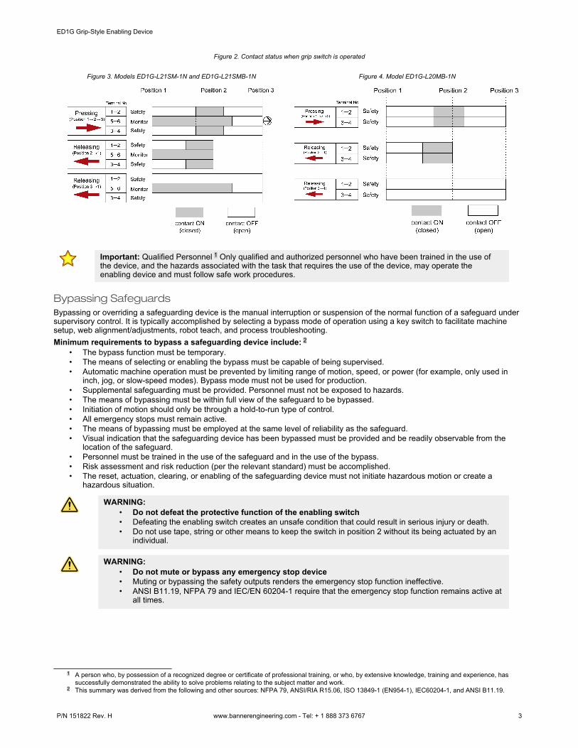
Figure 2. Contact status when grip switch is operated
Figure 3. Models ED1G-L21SM-1N and ED1G-L21SMB-1N Figure 4. Model ED1G-L20MB-1N
Important: Qualified Personnel 1 Only qualified and authorized personnel who have been trained in the use ofthe device, and the hazards associated with the task that requires the use of the device, may operate theenabling device and must follow safe work procedures.
Bypassing SafeguardsBypassing or overriding a safeguarding device is the manual interruption or suspension of the normal function of a safeguard undersupervisory control. It is typically accomplished by selecting a bypass mode of operation using a key switch to facilitate machinesetup, web alignment/adjustments, robot teach, and process troubleshooting.Minimum requirements to bypass a safeguarding device include: 2
• The bypass function must be temporary.• The means of selecting or enabling the bypass must be capable of being supervised.• Automatic machine operation must be prevented by limiting range of motion, speed, or power (for example, only used in
inch, jog, or slow-speed modes). Bypass mode must not be used for production.• Supplemental safeguarding must be provided. Personnel must not be exposed to hazards.• The means of bypassing must be within full view of the safeguard to be bypassed.• Initiation of motion should only be through a hold-to-run type of control.• All emergency stops must remain active.• The means of bypassing must be employed at the same level of reliability as the safeguard.• Visual indication that the safeguarding device has been bypassed must be provided and be readily observable from the
location of the safeguard.• Personnel must be trained in the use of the safeguard and in the use of the bypass.• Risk assessment and risk reduction (per the relevant standard) must be accomplished.• The reset, actuation, clearing, or enabling of the safeguarding device must not initiate hazardous motion or create a
hazardous situation.
WARNING:• Do not defeat the protective function of the enabling switch• Defeating the enabling switch creates an unsafe condition that could result in serious injury or death.• Do not use tape, string or other means to keep the switch in position 2 without its being actuated by an
individual.
WARNING:• Do not mute or bypass any emergency stop device• Muting or bypassing the safety outputs renders the emergency stop function ineffective.• ANSI B11.19, NFPA 79 and IEC/EN 60204-1 require that the emergency stop function remains active at
all times.
1 A person who, by possession of a recognized degree or certificate of professional training, or who, by extensive knowledge, training and experience, hassuccessfully demonstrated the ability to solve problems relating to the subject matter and work.
2 This summary was derived from the following and other sources: NFPA 79, ANSI/RIA R15.06, ISO 13849-1 (EN954-1), IEC60204-1, and ANSI B11.19.
ED1G Grip-Style Enabling Device
P/N 151822 Rev. H www.bannerengineering.com - Tel: + 1 888 373 6767 3

Lockout/TagoutRead OSHA 29CFR 1910.147 The control of hazardous energy (lockout/tagout) or ANSI 2244.1 Lockout/Tagout of Energy Sourcesin machine maintenance and servicing situations in which the unexpected energization, start up, or release of stored energy couldcause injury. Refer to these standards to ensure that bypassing a safeguarding device does not conflict with the requirements thatare contained within the standards.
WARNING:• Limit the use of the bypass and/or override function• Failure to follow these instructions could result in serious injury or death.• The bypass and/or override function is not intended for production purposes; use it only for temporary or
intermittent actions, such as to clear the defined area of a safety light curtain if material becomes stuck.When bypass and/or override is used, the user must install and use it according to applicable standards(such as NFPA 79 or IEC/EN60204-1).
Mechanical InstallationProvision to secure the enabling device is recommended and may be required as part of ensuring that the operation of the enablingdevice can be supervised. The enabling device must not be affected by environmental conditions. See Specifications.Install the enabling device so that it is protected against inadvertent operation (for example, accidental actuation by beingbumped or leaned against). All mounting hardware is user-supplied.
Electrical Installation
WARNING:• Risk of electric shock• Use extreme caution to avoid electrical shock. Serious injury or death could result.• Always disconnect power from the safety system (for example, device, module, interfacing, etc.),
guarded machine, and/or the machine being controlled before making any connections or replacing anycomponent. Lockout/tagout procedures might be required. Refer to OSHA 29CFR1910.147, ANSIZ244-1, or the applicable standard for controlling hazardous energy.
• Make no more connections to the device or system than are described in this manual. Electricalinstallation and wiring must be made by a Qualified Person 3 and must comply with the applicableelectrical standards and wiring codes, such as the NEC (National Electrical Code), NFPA 79, or IEC60204-1, and all applicable local standards and codes.
It is not possible to give exact wiring instructions for a Safety Module that interfaces to a multitude of machine control configurations.The following guidelines are general in nature.Use a risk assessment to determine the method of interfacing this device. At a minimum, use the same level of safety performance(for example, control reliability, category 3 or 4) for the safeguard being bypassed.Do not simply connect the contacts of the enabling switch across the contacts of a bypassed safeguarding device (forexample, interlocked guard/gate, safety light screen) in a parallel connection. The enabling device(s) could be rendered ineffectiveby simply re-establishing the safeguarding device (closing the interlocked guard/gate, clearing the safety light screen).At a minimum, the machine control must:
• Provide a means for supervising the selection of the enabling device to prevent unauthorized use or de-selection (disabling)while in use. Methods include key-operated controls, controls located under lockable covers, controls that require apassword, or securing th enabling device(s) within lockable storage.
• Reduce risk to the individual using the enabling device by reducing machine performance (such as reducing speed, reducingpower or force, or allowing only an incremental step-by-step operation, for example, inch/jog).
• Provide visual means to indicate the enabling device/function is active or has been selected.• Allow only one actuating control to initiate a machine cycle or function when the enabling device is in use to prevent
unexpected machine function.• Require each selected enabling device to concurrently operate before a machine cycle or function can be initiated.• Cause an immediate stop of the machine or function when the enabling device is released or fully squeezed. The enabling
device(s) must be re-actuated for the actuating control to be allowed to re-initiate a machine cycle or function.The means of returning the machine control to automatic or production mode must be located outside the hazard zone, such that itcan not be reached from within the hazard zone, and the reset procedure cannot be allowed to occur until the hazard zone is clear ofindividuals and all safeguards are reestablished (in place and functioning).
3 A person who, by possession of a recognized degree or certificate of professional training, or who, by extensive knowledge, training and experience, hassuccessfully demonstrated the ability to solve problems relating to the subject matter and work.
ED1G Grip-Style Enabling Device
4 www.bannerengineering.com - Tel: + 1 888 373 6767 P/N 151822 Rev. H

Consideration for Reset SwitchesThe safeguarding device (or safety system) reset switch (if used) must be accessible only from outside, and in full view of, thehazardous area. Reset switches must also be out of reach from within the safeguarded space, and must be protected againstunauthorized or inadvertent operation (for example, through the use of rings or guards). If any areas are not visible from the resetswitch(es), additional means of safeguarding must be provided.
WARNING:• Reset routine required• Failure to prevent the machine from restarting without actuating the normal start command/device can
create an unsafe condition that could result in serious injury or death.• Do not allow the machine to restart without actuating the normal start command/device. Perform the
reset routine after clearing the cause of a stop condition, as required by U.S. and internationalstandards.
Connection of Multiple SwitchesMultiple enabling devices connected to one safety module must be series connected (see wiring diagram and the following warning).
WARNING:• Connect two or more devices to the same safety module (controller) in series• Connecting devices in parallel defeats the switch contact monitoring ability of the module and creates an
unsafe condition that could result in serious injury or death.• Failure to test each device individually in this manner could result in undetected faults and create an
unsafe condition that could result in serious injury or death.• Connect the contacts of the corresponding pole of each switch in series. Never connect the contacts of
multiple switches in parallel. Individually actuate (engage) each device, then release (or re-arm) andreset the safety module. This allows the module to check each switch and its wiring to detect faults.Perform this check during the prescribed checkouts.
Normally Open Momentary Pushbutton (on Some Models)Models with the momentary switch option may be used to control a machine function, as an inch/jog button, or as a hold-to-runcontrol.Only one actuating control (for example, the pushbutton) can initiate the machine function while the enabling device(s) is in use. Toprevent unexpected machine function, the machine control must disable all other actuating controls such that the individual operatingthe enabling device has exclusive control.Hold-to-run control initiates and maintains machine functions only as long as the pushbutton is actuated; release of the pushbuttonmust initiate an immediate stopping command. For hold-to-run applications, both the three-position switch and the momentary N.O.switch must be continually engaged to allow machine operation. If multiple individuals are within the cell or exposed to the hazard,only a single individual can be in command of the hold-to-run control or the means to initiate machine operation.
Making the Connections: Accessing the Wiring ChamberTo ensure the highest level of reliability, connect both contacts to a monitoring device, such as a safety module.
Figure 5. Terminal assignments (dependent on model)
ED1G-L21SMB-1N
1 35 7 8 6 4 2
T 1 2 3
7 81 3 4 2
T 1 2 3
5 6 1 3 4 2
T 1 2 3
5 6
ED1G-L21SM-1N ED1G-L20MB-1N
1. Remove the cover from the switch by loosening the three M4 Phillips-head screws on the back of the housing.2. Detach the cable gland from the housing.3. Route the cables through the supplied cable gland and into the wiring chamber.
ED1G Grip-Style Enabling Device
P/N 151822 Rev. H www.bannerengineering.com - Tel: + 1 888 373 6767 5

4. Strip the wire as required and secure into the appropriate wiring terminals.Terminals 1 to 4 Terminals 5 to 8
Wire Length L1, L2 L1 = 35 mm L2 = 30 mm
Wire Stripping Length L3 L3 = 8 mm to 9 mm (or equivalent ferrule length)
Figure 6. Wire lengths to terminal connections
Terminal No.
Connector
Base
L1
L2
L3
L3
5. Replace the cover and secure with the three screws (torque: 1.1 N·m to 1.3 N·m).6. Thread the cable gland onto the housing and manually tighten (torque: 3.7 N·m to 4.3 N·m).
Note:• Applicable cordset/cable outside diameter when used with supplied cable gland: 7 mm to 13 mm.• Applicable wire size in terminal: 0.2 mm² to 1.5 mm² (single wire).• When using stranded wire, make sure that adjoining terminals are not short-circuited with protruding core
wires. Use copper wire with a 60 °C to 75 °C rating only (UL508).
Important: Clamp terminals are designed for one wire only. If more than one wire is connected to a terminal, awire could loosen or become completely disconnected from the terminal, causing a short.Use a stranded wire or a wire with an accompanying ferrule. Tinned wires are not recommended.After inserting the wire into the terminal, tug the wire to make sure it is properly retained. If the wire is notretained, consider using a different wiring solution.
Note: Older units (pre-2022) have screw terminals instead of clamp terminals. The position number is the same.
Wiring Example for Gate and Speed Monitoring Applications
WARNING:• Properly install arc or transient suppressors• Failure to follow these instructions could result in serious injury or death.• Install any suppressors as shown across the coils of the machine primary control elements. Do not
install suppressors directly across the output contacts of the safety or interface module. In such aconfiguration, it is possible for suppressors to fail as a short circuit.
ED1G Grip-Style Enabling Device
6 www.bannerengineering.com - Tel: + 1 888 373 6767 P/N 151822 Rev. H

Figure 7. Wiring example for gate and speed monitoring applications
To/From Inch/Jog or Hold-to-Run
Machine Control (3)
Enabling Device #1 +24Vdc
Bypass Mode Select Switch (1)
To Machine Control “Bypass Mode” (3)
Bypass Indicator
T 1 2 3
ED1G-L21SM-1N
T 1 2 3
ED1G-L21SMB-1N
ES-UA-5A
K1 K2 MPCE
1
M1 M2 M3 M4
Monitoring Circuit
Reset
Enabling Device #2 .. #n
ES-FA-11AA
K1 K2
From Reduced Speed Machine
Control (3)
To Reduced Speed Machine
Control (3)
Safe Speed Monitoring
Module (Optional) (4)
Reset (2)
(5)
OPEN
7 8 1 3 5 6 4 2 1 3 4 2
A1
S11
S21
S22
S12
13
23
31
14
24
32
A2
S33
S34
* Arc Suppressor (see warning)
MPCE2
MPCE3
MPCE4
A1
S11
S21
S22
S12
13
23
33
S31
S32
24
14
34
4443
A2
S34
S33
Functions requiring bypass
Functions not requiring bypass
Machine ControlCircuits
5 6
1. Selection of the enabling device must be capable of being supervised.2. In this example, the safety module monitoring the enabling device(s) is configured for manual reset, requiring a separate
action before the bypass can occur.3. Several signals are used to allow the bypass of the safeguard, including:
• The Bypass Mode Selector switch sends a signal to the machine control to enter a reduced performance mode (forexample, inch/jog, slow speed, etc.),
• The enabling switch (via the normally closed (NC) output of the ES-FA-11A safety module) enables the slow/reduced speed machine control function and bypasses the safeguard with the normally open (NO) outputs, and
• The momentary normally open (NO) button on the enabling device initiates the machine function.4. Additional logic, such as a safe speed / zero speed signal, may be required to ensure that the operator(s) are not exposed to
hazards generated from automatic machine operation.5. Multiple actions are required to return the machine to automatic or production mode, including closing the guard and
resetting the guard-monitoring safety module.
ED1G Grip-Style Enabling Device
P/N 151822 Rev. H www.bannerengineering.com - Tel: + 1 888 373 6767 7

Checkout ProceduresBanner Engineering highly recommends performing the System checkouts as described. However, a qualified person (or team)should evaluate these generic recommendations considering their specific application and determine the appropriate frequency ofcheckouts. This will generally be determined by a risk assessment, such as the one contained in ANSI B11.0. The result of the riskassessment will drive the frequency and content of the periodic checkout procedures and must be followed.
Initial and Daily ChecksVerify the functioning of the enabling device at initial installation (by a qualified person 4), daily or before each use (by a designatedperson), and as part of the regular periodic checkout procedure listed below 5 to ensure proper operation.
1. Inspect the device for breakage or damage and the interconnect cabling for crushing, cuts, or wear.2. Inspect the device for loosening or damage to the mounting hardware or means of storage.3. With the enabling device selected (for example, bypass or maintenance mode, inch/jog) and the safeguard disabled (for
example, interlock gate/guard open), verify that:• The bypass indicator illuminates, and• Hazardous function(s) can not be initiated when the enabling device is not actuated (position #1).
4. Actuate the enabling device (squeeze to position #2) and initiate hazardous machine function(s). Verify that the hazardousfunction ceases when the device is released (returned to position #1) or fully squeezed (position #3).
5. If more than one enabling device is used, perform this procedure individually for EACH device.
Periodic ChecksA qualified person 6 should check for the following on a periodic schedule determined by the user, based upon the severity of theoperating environment and the frequency of switch actuations. At a minimum, this should take place once a year (lockout/tagoutprocedures for controlling hazardous energy may be required):
1. Inspect the wiring chamber for signs of contamination, deterioration, loose connections, or damage.2. Inspect the sealing at the cable entry and all electrical wiring for continuity and damage.3. Verify the wiring and installation conforms to the instructions in this document and there are no signs of tampering or defeat.4. Perform the initial checkout.
See also the machine manufacturer's recommendations for additional instructions. If any of these checks cannot be verified, donot attempt to use the enabling device until the defect or problem has been corrected.
Specifications
Supply Voltage250 V AC/DC
Impulse Withstand Voltage3-position switch: 2.5 kVMomentary pushbutton: 1.5 kV
Output Contact RatingsSee table below.
Rated Thermal Current (Ith):2.5 A, for the following operating temperatures:
40 °C ≤ 50 °C: 2 A (4 contacts under load)50 °C ≤ 60 °C: 1.5 A (3 contacts under load)
Contact Resistance100 mΩ maximum
Shock ResistanceOperating extremes:150 m/s² (15 G)Damage limits: 1,000 m/s² (100 G)
Direct Opening(Terminals 5 and 6 models ED1G-L21SM-1N and ED1G-L21SMB-1N)Actuating Force: 70 N minimumTravel: 4.7 mm minimum
Date code format (U.S. Standard Format)YYWWX: 2-digit year, 2-digit week, "X” internal code
Pollution Degree3
Mechanical LifePositions 1 & 2 only: 1,000,000 operations minimumPositions 1, 2 & 3: 100,000 operations minimumOperating frequency: 1,200 operations per hour maximum
4 A qualified person possesses a recognized degree or certificate or has extensive knowledge, training, and experience to be able to solve problems relating tothe safety switch installation.
5 A designated person is identified in writing by the employer as being appropriately trained to perform a specified checkout procedure.6 A qualified person possesses a recognized degree or certificate or has extensive knowledge, training, and experience to be able to solve problems relating to
the safety switch installation.
ED1G Grip-Style Enabling Device
8 www.bannerengineering.com - Tel: + 1 888 373 6767 P/N 151822 Rev. H
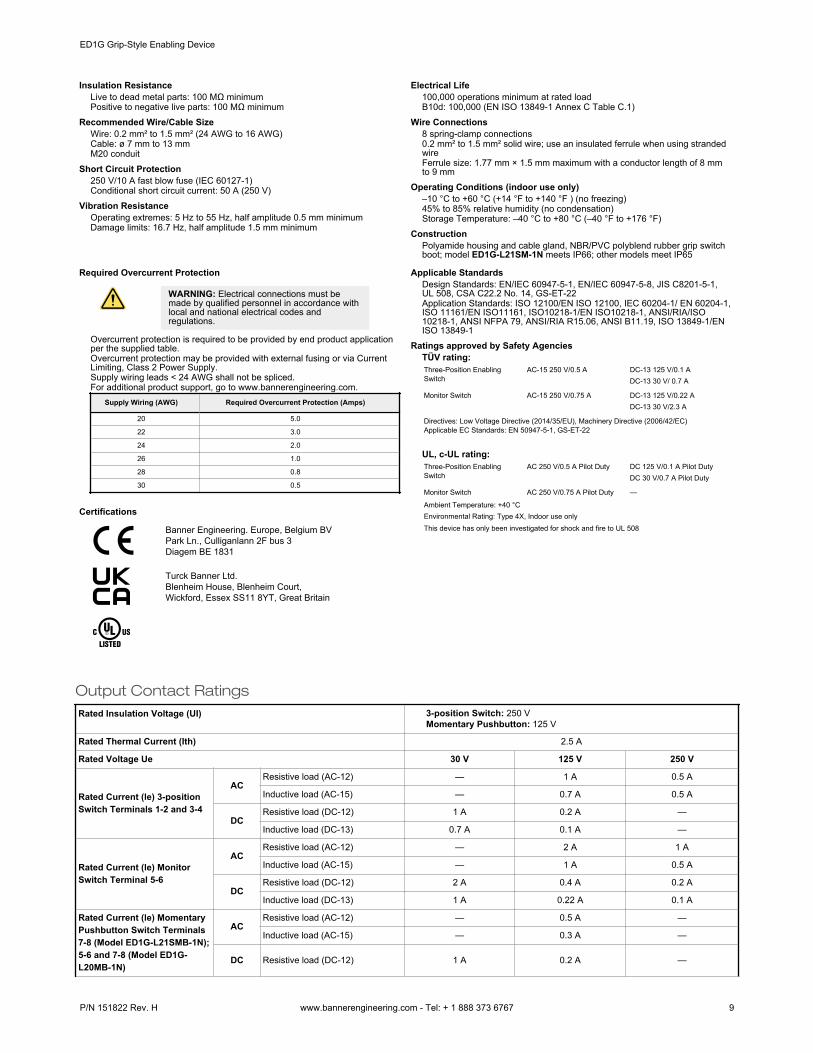
Insulation ResistanceLive to dead metal parts: 100 MΩ minimumPositive to negative live parts: 100 MΩ minimum
Recommended Wire/Cable SizeWire: 0.2 mm² to 1.5 mm² (24 AWG to 16 AWG)Cable: ø 7 mm to 13 mmM20 conduit
Short Circuit Protection250 V/10 A fast blow fuse (IEC 60127-1)Conditional short circuit current: 50 A (250 V)
Vibration ResistanceOperating extremes: 5 Hz to 55 Hz, half amplitude 0.5 mm minimumDamage limits: 16.7 Hz, half amplitude 1.5 mm minimum
Electrical Life100,000 operations minimum at rated loadB10d: 100,000 (EN ISO 13849-1 Annex C Table C.1)
Wire Connections8 spring-clamp connections0.2 mm² to 1.5 mm² solid wire; use an insulated ferrule when using strandedwireFerrule size: 1.77 mm × 1.5 mm maximum with a conductor length of 8 mmto 9 mm
Operating Conditions (indoor use only)–10 °C to +60 °C (+14 °F to +140 °F ) (no freezing)45% to 85% relative humidity (no condensation)Storage Temperature: –40 °C to +80 °C (–40 °F to +176 °F)
ConstructionPolyamide housing and cable gland, NBR/PVC polyblend rubber grip switchboot; model ED1G-L21SM-1N meets IP66; other models meet IP65
Required Overcurrent Protection
WARNING: Electrical connections must bemade by qualified personnel in accordance withlocal and national electrical codes andregulations.
Overcurrent protection is required to be provided by end product applicationper the supplied table.Overcurrent protection may be provided with external fusing or via CurrentLimiting, Class 2 Power Supply.Supply wiring leads < 24 AWG shall not be spliced.For additional product support, go to www.bannerengineering.com.
Supply Wiring (AWG) Required Overcurrent Protection (Amps)
20 5.0
22 3.0
24 2.0
26 1.0
28 0.8
30 0.5
Certifications
Banner Engineering. Europe, Belgium BVPark Ln., Culliganlann 2F bus 3Diagem BE 1831
Turck Banner Ltd.Blenheim House, Blenheim Court,Wickford, Essex SS11 8YT, Great Britain
Applicable StandardsDesign Standards: EN/IEC 60947-5-1, EN/IEC 60947-5-8, JIS C8201-5-1,UL 508, CSA C22.2 No. 14, GS-ET-22Application Standards: ISO 12100/EN ISO 12100, IEC 60204-1/ EN 60204-1,ISO 11161/EN ISO11161, ISO10218-1/EN ISO10218-1, ANSI/RIA/ISO10218-1, ANSI NFPA 79, ANSI/RIA R15.06, ANSI B11.19, ISO 13849-1/ENISO 13849-1
Ratings approved by Safety AgenciesTÜV rating:Three-Position EnablingSwitch
AC-15 250 V/0.5 A DC-13 125 V/0.1 ADC-13 30 V/ 0.7 A
Monitor Switch AC-15 250 V/0.75 A DC-13 125 V/0.22 ADC-13 30 V/2.3 A
Directives: Low Voltage Directive (2014/35/EU), Machinery Directive (2006/42/EC)Applicable EC Standards: EN 50947-5-1, GS-ET-22
UL, c-UL rating:Three-Position EnablingSwitch
AC 250 V/0.5 A Pilot Duty DC 125 V/0.1 A Pilot DutyDC 30 V/0.7 A Pilot Duty
Monitor Switch AC 250 V/0.75 A Pilot Duty —
Ambient Temperature: +40 °CEnvironmental Rating: Type 4X, Indoor use onlyThis device has only been investigated for shock and fire to UL 508
Output Contact RatingsRated Insulation Voltage (UI) 3-position Switch: 250 V
Momentary Pushbutton: 125 V
Rated Thermal Current (Ith) 2.5 A
Rated Voltage Ue 30 V 125 V 250 V
Rated Current (le) 3-positionSwitch Terminals 1-2 and 3-4
ACResistive load (AC-12) — 1 A 0.5 A
Inductive load (AC-15) — 0.7 A 0.5 A
DCResistive load (DC-12) 1 A 0.2 A —
Inductive load (DC-13) 0.7 A 0.1 A —
Rated Current (le) MonitorSwitch Terminal 5-6
ACResistive load (AC-12) — 2 A 1 A
Inductive load (AC-15) — 1 A 0.5 A
DCResistive load (DC-12) 2 A 0.4 A 0.2 A
Inductive load (DC-13) 1 A 0.22 A 0.1 A
Rated Current (le) MomentaryPushbutton Switch Terminals7-8 (Model ED1G-L21SMB-1N);5-6 and 7-8 (Model ED1G-L20MB-1N)
ACResistive load (AC-12) — 0.5 A —
Inductive load (AC-15) — 0.3 A —
DC Resistive load (DC-12) 1 A 0.2 A —
ED1G Grip-Style Enabling Device
P/N 151822 Rev. H www.bannerengineering.com - Tel: + 1 888 373 6767 9

Inductive load (DC-13) 0.7 A 0.1 A —
DimensionsAll measurements are listed in millimeters, unless noted otherwise.
Figure 8. Model ED1G-L21SM-1N
174
86
584654
Figure 9. Models ED1G-L21SMB-1N and ED1G-L20MB-1N
917
486
584654
MomentaryPushbutton
Accessories and Replacement Parts
Accessories Replacement Parts
ED9Z-GH1 Right-angle bracket
• Right-angle bracket mounts directly toupright surface
• Holds enabling switch for easy accesswhen needed
• All measurements in mm
Mounting hole for M5(2-φ 5.3)
Coating
86
50
81
2033
Material: SUS304Thickness: t=3.0 mm
ED9Z-GBK1-1N NBR/PVC gray Polyblend boot
• Identical to original boot shipped withenabling device
Rubber boot
EU/UK Declaration of Conformity (DoC)Banner Engineering Corp. herewith declares that these products are in conformity with the provisions of the listed directives,regulations, and all essential health and safety requirements have been met. For the complete DoC, please go to www.bannerengineering.com.Product Directive
ED1G Series Enabling Device EU: Machinery Directive 2006/42/EC and Low Voltage Directive2014/35/EUUK: Machinery (Safety) Regulations 2008
Representative in EU: Spiridon Lachanidis, Managing Director, Banner Engineering Europe Park Lane, Culliganlaan 2F bus 3,1831 Diegem, BELGIUMRepresentative in UK: Tony Coghlan, Managing Director, Turck Banner LTD Blenheim House, Blenheim Court, Wickford, EssexSS11 8YT, Great Britain
ED1G Grip-Style Enabling Device
10 www.bannerengineering.com - Tel: + 1 888 373 6767 P/N 151822 Rev. H

Banner Engineering Corp. Limited WarrantyBanner Engineering Corp. warrants its products to be free from defects in material and workmanship for one year following the date of shipment. Banner Engineering Corp. will repair orreplace, free of charge, any product of its manufacture which, at the time it is returned to the factory, is found to have been defective during the warranty period. This warranty does notcover damage or liability for misuse, abuse, or the improper application or installation of the Banner product.THIS LIMITED WARRANTY IS EXCLUSIVE AND IN LIEU OF ALL OTHER WARRANTIES WHETHER EXPRESS OR IMPLIED (INCLUDING, WITHOUT LIMITATION, ANYWARRANTY OF MERCHANTABILITY OR FITNESS FOR A PARTICULAR PURPOSE), AND WHETHER ARISING UNDER COURSE OF PERFORMANCE, COURSE OF DEALING ORTRADE USAGE.This Warranty is exclusive and limited to repair or, at the discretion of Banner Engineering Corp., replacement. IN NO EVENT SHALL BANNER ENGINEERING CORP. BE LIABLE TOBUYER OR ANY OTHER PERSON OR ENTITY FOR ANY EXTRA COSTS, EXPENSES, LOSSES, LOSS OF PROFITS, OR ANY INCIDENTAL, CONSEQUENTIAL OR SPECIALDAMAGES RESULTING FROM ANY PRODUCT DEFECT OR FROM THE USE OR INABILITY TO USE THE PRODUCT, WHETHER ARISING IN CONTRACT OR WARRANTY,STATUTE, TORT, STRICT LIABILITY, NEGLIGENCE, OR OTHERWISE.Banner Engineering Corp. reserves the right to change, modify or improve the design of the product without assuming any obligations or liabilities relating to any product previouslymanufactured by Banner Engineering Corp. Any misuse, abuse, or improper application or installation of this product or use of the product for personal protection applications when theproduct is identified as not intended for such purposes will void the product warranty. Any modifications to this product without prior express approval by Banner Engineering Corp will voidthe product warranties. All specifications published in this document are subject to change; Banner reserves the right to modify product specifications or update documentation at any time.Specifications and product information in English supersede that which is provided in any other language. For the most recent version of any documentation, refer to: www.bannerengineering.com.For patent information, see www.bannerengineering.com/patents.
ED1G Grip-Style Enabling Device
© Banner Engineering Corp. All rights reserved