Embed Size (px)
Citation preview

Factory---Installed Economizersfor TC/TCQ/HC/HCQ/LC/KC/KCQRooftop Units3 to 27.5 Nominal Tons
Economizer Supplement Related ToCalifornia Title 24
California’s new Title 24 is effective July 1, 2014 and requires several neweconomizer features.
This supplement details these economizer updates and is to be used inconjunction with the base unit installation instructions for the following3 to 27.5 nominal ton models: TC/TCQ/HC/HCQ/LC/KC/KCQ.
Supplement Index:
S EconoMi$er 2 DDC Title 24 offerings and definitions Page 2. . . . . . . . . . . . . . . . .NOTE: Wiring diagrams and instructions do not change.
S EconoMi$er X Title 24 electro--mechanical offerings and definitions Pages 3--24. . .This includes set up, start up and menu structure information.
Title 24 Note: Because the economizer factory--installed in the unit is Title 24 listed by theCalifornia Energy Commission (CEC), field economizer commissioning is not required.

2
Title 24 EconoMi$er 2 Supplement
The DDC economizer factory--installed in this rooftop unit meets some parts or all of the requirements ofthe new California Title 24 economizer standards.
There are (2) significant parts to the economizer section of Title 24:
— Mandatory section 120.2 Economizer Fault Detection and Diagnostics (FDD). This section’sintent is to allow only California Energy Commission (CEC) listed economizer controllers to beused to properly determine when an economizer control system fails and identifying the specificfailure. If your unit has either of these (2) Carrier control systems, the economizer meets Title 24section 120.2 mandatory FDD requirements.
S SystemVu control system(A field--installed Return Air Temperature sensor accessory is required to meet Title 24.)
S ComfortLink control system(A field--installed Return Air Temperature sensor accessory is required to meet Title 24.)
S RTU Open control system
— Prescriptive section 140.4 deals with several economizer related issues including minimaldamper leakage, damper life cycle testing, 5 year economizer warranty, etc. Because section140.4 is “prescriptive” they may not be required on some jobs. When an economizer with “UltraLow Leak” dampers is ordered, it meets the section 140.4 requirements.
NOTE: These economizers also meet ASHRAE 90.1 requirements.
Carrier factory--installed economizers that meet some or all of Title 24 are:
ECONOMIZER TYPE CONTROLLER DAMPER MEETS TITLE 24
Economizer 2 SystemVu Ultra Low Leak Section 120.2 and 140.4
Economizer 2 ComfortLink Ultra Low Leak Section 120.2 and 140.4
Economizer 2 ComfortLink Standard Leak Section 120.2
Economizer 2 RTU Open Ultra Low Leak Section 120.2 and 140.4
Economizer 2 RTU Open Standard Leak Section 120.2
NOTE: PremierLink controller does not meet Title 24 section 120.2
SUP--TI24--02SI

3
Title 24 EconoMi$er X SupplementELECTRO--MECHANICAL CONTROLS
The economizer factory--installed in this rooftop unit meets some parts or all of the requirements of the newCalifornia Title 24 economizer standards.
There are (2) significant parts to the economizer section of Title 24:
— Mandatory section 120.2 Economizer Fault Detection and Diagnostics (FDD). This section’sintent is to allow only California Energy Commission (CEC) listed economizer controllers to beused to properly determine when an economizer control system fails and identifying the specificfailure. Carrier offers the EconoMi$er X control system, using the W7220 Honeywell controller,that meet the mandatory section 120.2 FDD requirements:
— Prescriptive section 140.4 deals with several economizer related issues including minimaldamper leakage, damper life cycle testing, 5 year economizer warranty, etc. Because section140.4 is “prescriptive” they may not be required on some jobs. When an economizer with “UltraLow Leak” dampers is ordered, it meets the section 140.4 requirements.
NOTE: These economizers also meet ASHRAE 90.1 requirements.
Carrier factory--installed economizers that meet some or all of Title 24 are:
ECONOMIZER TYPE CONTROLLER DAMPER MEETS TITLE 24
EconoMi$er X Honeywell W7220 Ultra Low Leak Section 120.2 and 140.4
EconoMi$er X Honeywell W7220 Standard Leak Section 120.2
The EconoMi$er X W7220 controller is factory set for either a 1 speed or 2 speed unit, depending uponthe unit ordered.
NOTE: EconoMi$er X can also be used with 3 speed LC units.
The following section provides general information and typical wiring diagrams for the W7220controller.
SUP--TI24--02SI
4
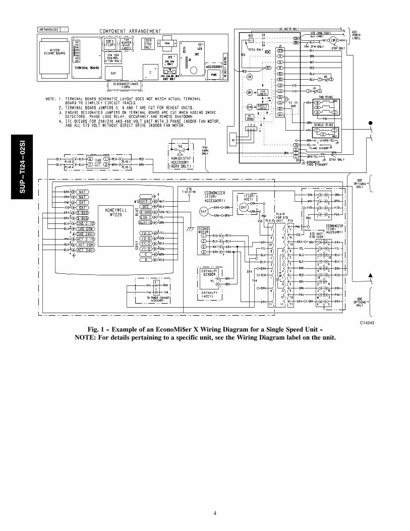
C14243
Fig. 1 -- Example of an EconoMi$er X Wiring Diagram for a Single Speed Unit --NOTE: For details pertaining to a specific unit, see the Wiring Diagram label on the unit.
SUP--TI24--02SI

5
C14336Fig. 2 -- Example of an EconoMi$er X Wiring Diagram for a 2 Speed Unit --
NOTE: For details pertaining to a specific unit, see the Wiring Diagram label on the unit.
SUP--TI24--02SI
6
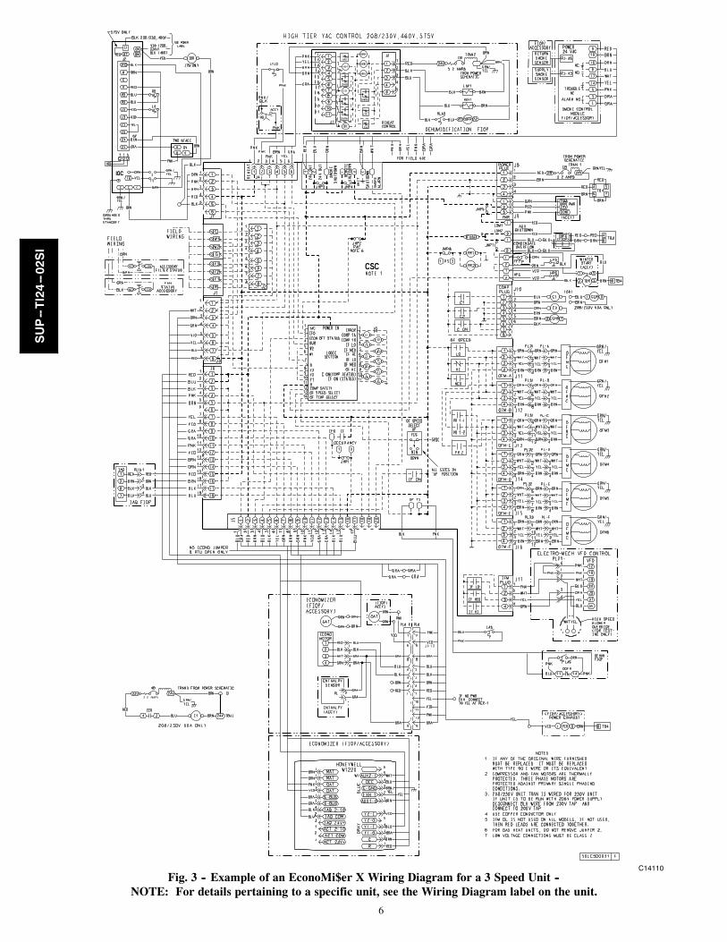
C14110Fig. 3 -- Example of an EconoMi$er X Wiring Diagram for a 3 Speed Unit --
NOTE: For details pertaining to a specific unit, see the Wiring Diagram label on the unit.
SUP--TI24--02SI

7
SAFETY CONSIDERATIONS
Improper installation, adjustment, alteration, service,maintenance, or use can cause explosion, fire, electricalshock or other conditions which may cause personalinjury or property damage. Consult a qualified installer,service agency, or your distributor or branch forinformation or assistance. The qualified installer oragency must use factory--authorized kits or accessorieswhen modifying this product. Refer to the individualinstructions packaged with the kits or accessories wheninstalling.
Follow all safety codes. Wear safety glasses and workgloves. Use quenching cloths for brazing operations andhave a fire extinguisher available. Read these instructionsthoroughly and follow all warnings or cautions attached tothe unit. Consult local building codes and appropriatenational electrical codes (in USA, ANSI/NFPA70,National Electrical Code (NEC); in Canada, CSA C22.1)for special requirements.
It is important to recognize safety information. This is the
safety--alert symbol . When you see this symbol on theunit and in instructions or manuals, be alert to thepotential for personal injury.
Understand the signal words DANGER, WARNING,CAUTION, and NOTE. These words are used with thesafety--alert symbol.
DANGER identifies the most serious hazards which willresult in severe personal injury or death. WARNINGsignifies hazards which could result in personal injury ordeath.
CAUTION is used to identify unsafe practices, whichmay result in minor personal injury or product andproperty damage.
NOTE is used to highlight suggestions which will result inenhanced installation, reliability, or operation.
ELECTRICAL SHOCK HAZARD
Failure to follow this warning could cause personalinjury or death.
Before performing service or maintenance operationson unit, always turn off main power switch to unit andinstall lock(s) and lockout tag(s). Unit may have morethan one power switch. Ensure electrical service torooftop unit agrees with voltage an amperage listed onthe unit rating plate.
WARNING!
CUT HAZARD
Failure to follow this caution may result in personal injury.
Sheet metal parts may have sharp edges or burrs. Usecare and wear appropriate protective clothing, safetyglasses and gloves when handling parts and servicingair conditioning equipment.
CAUTION!
SUP--TI24--02SI
8
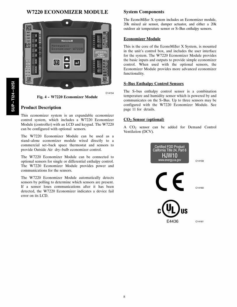
W7220 ECONOMIZER MODULE
C14154
Fig. 4 -- W7220 Economizer Module
Product Description
This economizer system is an expandable economizercontrol system, which includes a W7220 EconomizerModule (controller) with an LCD and keypad. The W7220can be configured with optional sensors.
The W7220 Economizer Module can be used as astand--alone economizer module wired directly to acommercial set--back space thermostat and sensors toprovide Outside Air dry--bulb economizer control.
The W7220 Economizer Module can be connected tooptional sensors for single or differential enthalpy control.The W7220 Economizer Module provides power andcommunications for the sensors.
The W7220 Economizer Module automatically detectssensors by polling to determine which sensors are present.If a sensor loses communications after it has beendetected, the W7220 Economizer indicates a device failerror on its LCD.
System Components
The EconoMi$er X system includes an Economizer module,20k mixed air sensor, damper actuator, and either a 20koutdoor air temperature sensor or S--Bus enthalpy sensors.
Economizer Module
This is the core of the EconoMi$er X System, is mountedin the unit’s control box, and includes the user interfacefor the system. The W7220 Economizer Module providesthe basic inputs and outputs to provide simple economizercontrol. When used with the optional sensors, theEconomizer Module provides more advanced economizerfunctionality.
S--Bus Enthalpy Control Sensors
The S--bus enthalpy control sensor is a combinationtemperature and humidity sensor which is powered by andcommunicates on the S--Bus. Up to three sensors may beconfigured with the W7220 Economizer Module. Seepage 11 for details.
CO2 Sensor (optional)
A CO2 sensor can be added for Demand ControlVentilation (DCV).
Certified FDD ProductCalifornia Title 24, Part 6
www.energy.ca.govHJW10
E4436
C14159
C14160
C14161
SUP--TI24--02SI

9
SPECIFICATIONS
W7220 Economizer Module
The module is designed for use with 2 to 10Vdc or buscommunicating actuator. The module includes terminalsfor CO2 sensor, Mixed Air sensor, and an Outdoor DryBulb sensor. Enthalpy and other options are available withbus sensors.
User Interface: Provides status for normal operation,setup parameters, checkout tests, and alarm and errorconditions with a 2--line 16 character LCD display andfour button keypad.
Electrical
Rated Voltage: 20 to 30 Vac RMS, 50/60 HzTransformer: 100 va maximum system input
Nominal Power Consumption (at 24 Vac, 60 Hz):11.5 VA without sensors or actuators
Relay Digital Output Rating at 30 Vac (maximumpower from Class 2 input only): 1.5A run:
3.5A inrush @ 0.45PF (200,000 cycles) or7.5A inrush @ 0.45PF (100,000 cycles)
External Sensors Power Output: 21 Vdc 5% @ 48mA
IMPORTANT: All inputs and outputs must be Class 2wiring.
Inputs
SENSORS:
NOTE: A Mixed Air (MA) analog sensor is required onall W7220 units; either an Outdoor Air (OA) sensor fordry bulb change over or an OA bus sensor for outdoorenthalpy change over is required in addition to the MAsensor. An additional Return Air (RA) bus sensor can beadded to the system for differential enthalpy or dry bulbchangeover. For differential dry bulb changeover a 20kohm sensor is required in the OA and a bus sensor in theRA. Dip switch on RA bus sensor must be set in the RAposition.
Dry Bulb Temperature (optional) and Mixed Air(required), 20k NTC:2--wire (18 to 22 AWG);Temperature range --40 to 150_F (--40 to 65_C).Temperature accuracy --0_F/+2_F
Temperature and Humidity, C7400S1000 (optional):S--Bus; 2--wire (18 to 22 AWG)Temperature: range --40 to 150_F (--40 to 65_C)Temperature accuracy --0_F/+2_FHumidity: range 0 to 100% RH with 5% accuracy.
NOTE: Up to three (3) S--Bus sensors may be connectedto the W7220 Economizer module. For outdoor air (OA),return air (RA) and discharge (supply) air (DA).
4 Binary inputs:1--wire 24 Vac + common GND (see page 11 for wiringdetails). 24 Vac power supply: 20 to 30 Vac 50/60Hz;100 VA Class 2 transformer.
Outputs
Actuator signal: 2--10 Vdc; minimum actuator impedanceis 2k ohm; bus two--wire output for bus communicatingactuators.
Exhaust fan, Y1, Y2 and AUX1 O:All Relay Outputs (at 30 Vac):
Running: 1.5A maximumInrush: 7.5A maximum
Environmental
Operating Temperature: --40 to 150_F (--40 to 65_C).Exception of display operation down to --4_F with fullrecovery at --4_F from exposure to --40_F
Storage Temperature: --40 to 150_F (--40 to 65_C)
Shipping Temperature: --40 to 150_F (--40 to 65_C)
Relative Humidity: 5% to 95% RH non--condensing
Dimensions (see Fig. 5, below):Height: 4.98 inches (126.4 mm)Width: 6.3 inches (160 mm)Depth: 1.34 inches (34 mm)
Weight: 0.58 lb. (0.265 kg)
6-19/64 (160)
4-63/64(126)
3-5/32 (80)MOUNTING HOLE (X2)
C14155
Fig. 5 -- Dimensions for Mounting Holes in Inches (mm)
BEFORE INSTALLATION
Review the “SPECIFICATIONS’ (above) before installingthe W7220A economizer module.
When Installing This Product1. Read these instructions carefully. Failure to follow
them could damage the product or cause a hazardouscondition.
2. Check ratings given in instructions and on the productto ensure the product is suitable for your application.
3. Installer must be a trained, experienced servicetechnician.
4. After installation is complete, check out productoperation as provided in these instructions.
SUP--TI24--02SI

10
NOTE: The W7220 will be in the ”set up” mode for thefirst 60 minutes after powered. If a sensor for OA air orbus device (sensor, actuator) is disconnected during the setup mode, the W7220 will not alarm that failure. The MAsensor is a system ”critical”sensor, if the MA sensor isremoved during the set up mode, the W7220 will alarm.After 60 minutes the W7220 controller will change tooperation mode and all components removed or failed willalarm in the operation mode.
INSTALLATION AND SETUP
The following installation procedures should beperformed in the order listed:
1. Mounting — see Fig. 5 (on page 9).2. Wiring — see pages 4, 5 and 6.3. Interface and Programming overview – see page 11.4. Setup and Configuration — see page 125. Checkout — see page 23.
Troubleshooting and Alarms—see page 24.
Economizer Module Wiring Details
The wiring connection terminals for each module/sensor are:
S “W7220 Economizer Module Wiring” on pages 10 -- 11.
S “S--Bus Sensor Wiring” on page 11
W7220 Economizer Module Wiring
Use Fig. 6 and Tables 1 and 2 to locate the wiringterminals for the Economizer module.
NOTE: The four terminal blocks are removable. You canslide out each terminal block, wire it, and then slide itback into place.
W7220 Controller
Left TerminalBlock Label
Right TerminalBlock Label
NOTE: The bottom 4 Pin actuator header is not used
C14156
Fig. 6 -- W7220 Economizer Module TerminalConnection Labels.
Table 1 – Economizer Module --Left Hand Terminal Blocks
Label Type Description
Top Left Terminal Block
MATMAT
20k NTCandCOM
Supply Air Temperature Sensor(polarity insensitive connection)
OATOAT
20k NTCandCOM
Outdoor Air Temperature Sensor(polarity insensitive connection)
S---BUSS---BUS
S---Bus(Sylk Bus)
Enthalpy Control Sensor(polarity insensitive connection)
Bottom Left Terminal Block
IAQ 2---10 2---10 Vdc Air Quality Sensor Input(e.g. CO2 sensor)
IAQ COM COM Air Quality Sensor Common
IAQ 24V 24 Vac Air Quality Sensor 24 Vac Source
ACT 2---10 2---10 Vdc Damper Actuator Output (2---10 Vdc)
ACT COM COM Damper Actuator Output Common
ACT 24V 24 Vac Damper Actuator 24 Vac Source
n/a The bottom pin is not used.
Table 2 – Economizer Module --Right Hand Terminal Blocks
Label Type Description
Top Right Terminal Block
n/a The first pin is not used
AUX2 I 24 Vac IN Shut Down (SD) or Heat (W)Conventional onlyor
Heat Pump Changeover (O/B) inHeat Pump mode.
OCC 24 Vac IN Occupied / Unoccupied Input
E---GND E---GND Earth Ground --- System Required
EXH1 24 Vac OUT Exhaust Fan 1 Output
AUX1 O 24 Vac OUT Programmable:Exhaust fan 2 outputorErvorSystem Alarm output
Bottom Right Terminal Block
Y2--- I 24 Vac IN Y2 in --- Cooling Stage 2 Input fromspace thermostat
Y2---O 24 Vac OUT Y2 out --- Cooling Stage 2 Output tostage 2 mechanical cooling
Y1--- I 24 Vac IN Y1 in --- Cooling Stage 1 Input fromspace thermostat
Y1---O 24 Vac OUT Y1 out --- Cooling Stage 1 Output tostage 1 mechanical cooling
C COM 24 Vac Common
R 24 Vac 24 Vac Power (Hot)
SUP--TI24--02SI
11
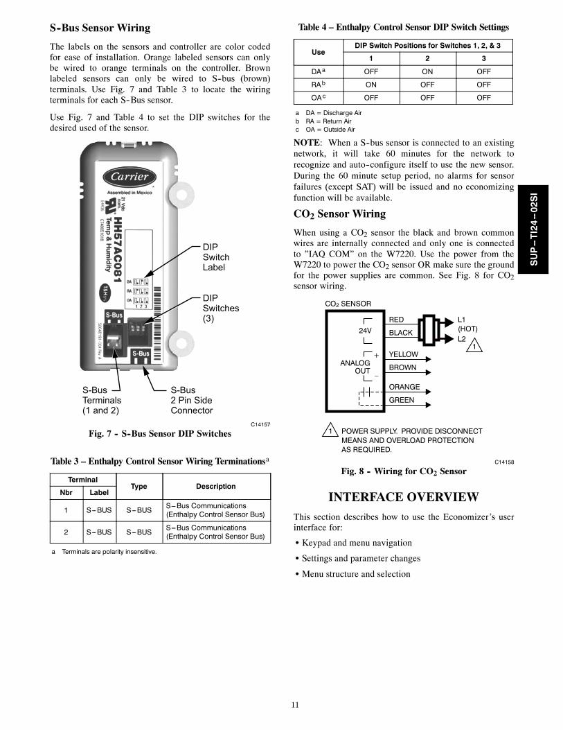
S--Bus Sensor Wiring
The labels on the sensors and controller are color codedfor ease of installation. Orange labeled sensors can onlybe wired to orange terminals on the controller. Brownlabeled sensors can only be wired to S--bus (brown)terminals. Use Fig. 7 and Table 3 to locate the wiringterminals for each S--Bus sensor.
Use Fig. 7 and Table 4 to set the DIP switches for thedesired used of the sensor.
DIPSwitchLabel
DIPSwitches(3)
S-Bus2 Pin SideConnector
S-BusTerminals(1 and 2)
C14157
Fig. 7 -- S--Bus Sensor DIP Switches
Table 3 – Enthalpy Control Sensor Wiring Terminationsa
TerminalType Description
Nbr Label
1 S---BUS S---BUS S---Bus Communications(Enthalpy Control Sensor Bus)
2 S---BUS S---BUS S---Bus Communications(Enthalpy Control Sensor Bus)
a Terminals are polarity insensitive.
Table 4 – Enthalpy Control Sensor DIP Switch Settings
UseDIP Switch Positions for Switches 1, 2, & 3
1 2 3
DAa OFF ON OFF
RAb ON OFF OFF
OAc OFF OFF OFF
a DA = Discharge Airb RA = Return Airc OA = Outside Air
NOTE: When a S--bus sensor is connected to an existingnetwork, it will take 60 minutes for the network torecognize and auto--configure itself to use the new sensor.During the 60 minute setup period, no alarms for sensorfailures (except SAT) will be issued and no economizingfunction will be available.
CO2 Sensor Wiring
When using a CO2 sensor the black and brown commonwires are internally connected and only one is connectedto ”IAQ COM” on the W7220. Use the power from theW7220 to power the CO2 sensor OR make sure the groundfor the power supplies are common. See Fig. 8 for CO2sensor wiring.
CO2 SENSOR
24V
ANALOGOUT
L1(HOT)L2
RED
BLACK
YELLOW
BROWN
ORANGE
GREEN
+
–
POWER SUPPLY. PROVIDE DISCONNECT MEANS AND OVERLOAD PROTECTIONAS REQUIRED.
1
1
C14158
Fig. 8 -- Wiring for CO2 Sensor
INTERFACE OVERVIEW
This section describes how to use the Economizer’s userinterface for:
S Keypad and menu navigation
S Settings and parameter changes
S Menu structure and selection
SUP--TI24--02SI

12
User Interface
The user interface consists of a 2--line LCD display and a4--button keypad on the front of the economizer controller.
2 LINELCD
MENU UP(EXIT)
BUTTONSCROLL
UP/DOWNBUTTONS
SELECT(ENTER)BUTTON
C14206
Fig. 9 -- W7220 Controller
Keypad
The four navigation buttons (see Fig. 9) are used to scrollthrough the menus and menu items, select menu items,and to change parameter and configuration settings.
Using the Keypad with Menus
To use the keypad when working with menus:
S Press the (Up arrow) button to move to the previous
menu.
S Press the (Down arrow) button to move to the nextmenu.
S Press the (Enter) button to display the first item in
the currently displayed menu.
S Press the (Menu Up/Exit) button to exit a menu’s
item and return to the list of menus.
Using the Keypad with Settings and Parameters
To use the keypad when working with Setpoints, Systemand Advanced Settings, Checkout tests and Alarms:
1. Navigate to the desired menu.2. Press the (Enter) button to display the first item in
the currently displayed menu.3. Use the and buttons to scroll to the desired
parameter.4. Press the (Enter) button to display the value of the
currently displayed item.5. Press the button to increase (change) the displayed
parameter value.6. Press the button to decrease (change) the displayed
parameter value.
NOTE: When values are displayed, pressing andholding the or button causes thedisplay to automatically increment.
7. Press the (Enter) button to accept the displayedvalue and store it in nonvolatile RAM.
8. “CHANGE STORED” displays.9. Press the (Enter) button to return to the current
menu parameter.10. Press the (Menu Up/Exit) button to return to the
previous menu.
Menu Structure
Table 5, starting on page 13, illustrates the completehierarchy of menus and parameters for the EconoMi$er Xsystem.
The Menus in display order are:
S STATUS
S SETPOINTS
S SYSTEM SETUP
S ADVANCED SETUP
S CHECKOUT
S ALARMS
IMPORTANT: Table 5 illustrates the complete hierarchy.Your menu parameters may be different depending onyour configuration.
For example if you do not have a DCV (CO2) sensor, thennone of the DCV parameters appear and only MIN POSwill display. If you have a CO2 sensor, the DCV MIN andDCV MAX will appear AND if you have 2 speed fanDCV MIN (high and low speed) and DCV MAX (highand low speed will appear).
NOTE: Some parameters in the menus use the letters MAor MAT, indicating a mixed air temperature sensorlocation before the cooling coil. This unit application hasthe control sensor located after the cooling coil, in the fansection, where it is designated as (Cooling) Supply AirTemperature or SAT sensor.
SETUP AND CONFIGURATION
Before being placed into service, the W7220 Economizermodule must be setup and configured for the installedsystem.
IMPORTANT: During setup, the Economizer module islive at all times.
The setup process uses a hierarchical menu structure thatis easy to use. You press the and arrow buttons tomove forward and backward through the menus and pressthe button to select and confirm setup item changes.
Time--out and Screensaver
When no buttons have been pressed for 10 minutes, theLCD displays a screen saver, which cycles through theStatus items. Each Status items displays in turn and cyclesto the next item after 5 seconds.
SUP--TI24--02SI

13
Table 5 – Menu Structurea
Menu ParameterParameterDefaultValue
ParameterRange and Incrementb
EXPANDED PARAMETER NAMENotes
STATUS ECON AVAIL NO YES/NO ECONOMIZING AVAIALBLEYES = economizing available; the system can use outside air for freecooling when required
ECONOMIZING NO YES/NO ECONOMIZING ACTIVEYES = Outside air being used for 1st stage cooling.NO = Economizing not active
OCCUPIED NO YES/NO OCCUPIEDYES = OCC signal received from space thermostator unitary controller.YES = 24 Vac on terminal OCC.NO = 0 Vac on terminal OCC.
HEAT PUMP n/a c COOLHEAT
HEAT PUMP MODEDisplays COOL or HEAT when system is set to heat pump(non---conventional)
COOL Y1---IN OFF ON/OFF FIRST STAGE COOLING DEMAND (Y1---IN)Y1---I signal from space thermostat or unitary controller for Cooling Stage 1.ON = 24 Vac on terminal Y1---IOFF = 0Vac on terminal Y1---I
COOL Y1---OUT OFF ON/OFF FIRST STAGE COOLING RELAY OUTPUTCool Stage 1 Relay Output to mechanical cooling (Y1---OUT terminal).
COOL Y2---IN OFF ON/OFF SECOND STAVE COOLING DEMAND (Y2---IN)Y2---I signal from space thermostat or unitary controller for Cooling Stage 2.ON = 24 Vac on terminal Y2---IOFF = 0 Vac on terminal Y2---I
COOL Y2---OUT OFF ON/OFF SECOND STAGE COOLING RELAY OUTPUTCool Stage 2 Relay Output to mechanical cooling (Y2---OUT terminal).
MA TEMP _ _.__F(or _ _.__C)
---40 to 150_F(---18 to 60_C)
SUPPLY AIR TEMPERATRUE, Cooling ModeDisplays value of measured mixed/cooled air from SAT sensor in fansection.Displays --- ---.--- if not connected, short or out---of---range. See Menu Note 2
DA TEMP _ _.__F(or _ _.__C)
---40 to 150_F(---18 to 60_C)
DISCHARGE AIR TEMPERATRUE, after Heating section(Accessory sensor required)Displays when Discharge Air sensor is connected and displays measureddischarge temperature.Displays --- ---.---_F if sensor sends invalid value, if not connected, short orout---of---range.
OA TEMP _ _.__F(or _ _.__C)
---40 to 140_F(---40 to 60_C)
OUTSIDE AIR TEMPERATRUEDisplays measured value of outdoor air temperature.Displays --- ---_F if sensor sends invalid value, if not connected, short orout---of---range.
OA HUM _ _% 0 to 100% OUTSIDE AIR RELATIVE HUMIDITYDisplays measured value of outdoor humidity from OA enthalpy sensor.
RA TEMP _ _.__F(or _ _.__C)
0 to 140_F(---18 to 60_C)
RETURN AIR TEMPERATRUE(Accessory sensor required)Displays measured value of return air temperature from RAT sensor.Displays --- ---_F if sensor sends invalid value, if not connected, short orout---of---range.
RA HUM _ _% 0 to 100% RETURN AIR RELATIVE HUMIDITY(Accessory enthalpy sensor required)Displays measured value of return air humidity from RA sensor.Displays --- ---% if sensor sends invalid value, if not connected, short orout---of---range.
IN CO2 _ _ _ ppm 0 to 2000 ppm SPACE/RETURN AIR CO2(CO2 sensor required, accessory or factory option)Displays value of measured CO2 from CO2 sensor.Invalid if not connected, short or out---of---range. May be adjusted inAdvanced menu by Zero offset and Span.
DCV STATUS n/a ON/OFF DEMAND CONTROL VENTILATION STATUS(CO2 sensor required, accessory or factory option)Displays ON if IN CO2 value above setpoint DCV SET and OFF if belowsetpoint DCV SET.
DAMPER OUT 2.0V 2.0 to 10.0V Displays output voltage or position to the damper actuator. e
ACT POS n/a 0 to 100% Displays actual position of outdoor air damper actuator
ACT COUNT n/a 1 to 65535 Displays number of times actuator has cycled.1 Cycle equals accrued 180_ of actuator movement in any direction
ACTUATOR n/a OK/Alarm(on Alarm menu)
Displays Error if voltage or torque is below actuator range
EXH1 OUT OFF ON/OFF EXHAUST STAGE 1 RELAY OUTPUTOutput of EXH1 terminal. Displays On when damper position reachesprogrammed percentage setpoint.ON = 24 Vac Output; OFF = No Output.
SUP--TI24--02SI

14
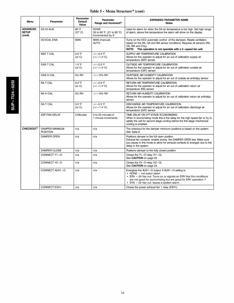
Table 5 -- Menu Structurea (cont)
Menu ParameterParameterDefaultValue
ParameterRange and Incrementb
EXPANDED PARAMETER NAMENotes
STATUS(cont)
EXH2 OUT OFF ON/OFF EXHAUST STAGE 2 RELAY OUTPUTOutput of AUX1 O terminal Displays ON when damper position reachesprogrammed percentage setpointON = 24 Vac Output, OFF = No Output; displays only if AUX1 O =EXH2
ERV OFF ON/OFF ENERGY RECOVERY UNIT RELAY OUTPUTOutput of AUX1 O terminal, ON = 24 Vac Output, OFF = No Output;displays only if AUX1 O = ERV
MECH COOL ONorHEAT STAGES ON
0 0, 1, or 2 Displays stage of mechanical cooling that is active.
Displays the stage of heat pump heating that is active
FAN SPEED n/a LOW or HIGH SUPPLY FAN SPEEDDisplays speed setting of fan on a 2---speed fan unit.
W (HEAT ON) n/a ON/OFF HEAT DEMAND STATUSDisplays status of heat demand on a 2---speed fan unit.
SETPOINTS MAT SET 53_F(12_C)
38 to 70_F;(3 to 21_C)increment by 1
SUPPLY AIR SETPOINTSetpoint determines where the economizer will modulate the OA damper tomaintain the mixed air temperature.See Menu Note 2.
LOW T LOCK 32_F(0_C)
---45 to 80_F;( ---43 to 27_C)increment by 1
COMPRESSOR LOW TEMPERATURE LOCKOUTSetpoint determines outdoor temperature when the mechanical coolingcannot be turned on. Commonly referred to as the Compressor lockout. Ator below the setpoint the Y1---O and Y2---O will not be energized on thecontroller.
DRYBLB SET 63_F(17_C)
48 to 80_F(9 to 27_C)increment by 1
OA DRY BULB TEMPERATURE CHANGEOVER SETPOINTSetpoint determines where the economizer will assume outdoor airtemperature is good for free cooling; e.g.: at 63_F (17_C), unit willeconomize at 62_F (16.7_C) and below and not economize at 64_F(17.8_C) and above. There is a 2_F (1.1_C)deadband.See Menu Note 3
ENTH CURVE ES3 ES1, ES2, ES3, ES4, orES5
ENTHALPY CHANGEOVER CURVE(Requires enthalpy sensor option)Enthalpy boundary “curves” for economizing using single enthalpy.See page 22 for description of enthalpy curves.
DCV SET 1100ppm 500 to 2000 ppm;increment by 100
DEMAND CONTROL VENTILATION SETPOINTDisplays only if CO2 sensor is connected. Setpoint for Demand ControlVentilation of space. Above the setpoint, the OA dampers will modulateopen to bring in additional OA to maintain a space ppm level below thesetpoint.
MIN POS 2.8 V 2 to 10 Vdc VENTILATION MINIMUM POSITIONDisplays ONLY if a CO2 sensor is NOT connected.
With 2---speed fan units MIN POS L (low speed fan) and MIN POS H (highspeed fan) settings are required. Default for MIN POS L is 3.2V and MINPOS H is 2.8V.
VENTMAX 2.8 V 2 to 10 Vdc DCV MAXIMUM DAMPER POSITIONDisplays only if a CO2 sensor is connected. Used for Vbz (ventilation maxcfm) setpoint. VENTMAX is the same setting as MIN POS would be if youdid not have the CO2 sensor.
100 to 9990 cfmincrement by 10
If OA, MA RA and CO2 sensors are connected and DCV CAL ENABLE isset to AUTO mode, the OA dampers are controlled by CFM and displaysfrom 100 to 9990 cfm.
2 to 10 Vdc With 2---speed fan units VENTMAX L (low speed fan) and VENTMAX H(high speed fan) settings are required. Default for VENTMAX L is 3.2V andVENTMAX H is 2.8V.
VENTMIN 2.25 V 2 to 10 Vdc DCV MINIMUM DAMPER POSITIONDisplays only if CO2 sensor is connected. Used for Va (ventilation min cfm)setpoint. This is the ventilation requirement for less than maximumoccupancy of the space.
100 to 9990 cfmincrement by 10
If OA, MA RA and CO2 sensors are connected and DCV CAL ENABLE isset to AUTO mode, the OA dampers are controlled by CFM and displaysfrom 100 to 9990 cfm.
2 to 10 Vdc With 2---speed fan units VENTMIN L (low speed fan) and VENTMIN H(high speed fan) settings are required. Default for VENTMIN L is 2.5Vand VENTMIN H is 2.25V.
ERV OAT SPd 32_F(0_C)
0 to 50_F;( ---18 TO 10_C)increment by 1
ENERGY RECOVERY VENTILATION UNIT OUTDOOR AIR TEMPERATURESETPOINTOnly when AUX1 O = ERV
EXH1 SET 50% 0 to 100%;Increment by 1
EXHAUST FAN STAGE 1 SETPOINTSetpoint for OA damper position when exhaust fan 1 is powered by theeconomizer.With 2---speed fan units Exh1 L (low speed fan) and Exh1 H (high speedfan) settings are required. Default for Exh1 L is 65% and Exh1 H is 50%
SUP--TI24--02SI

15
Table 5 -- Menu Structurea (cont)
Menu ParameterParameterDefaultValue
ParameterRange and Incrementb
EXPANDED PARAMETER NAMENotes
SETPOINTS(cont)
EXH2 SET 75% 0 to 100%;Increment by 1
EXHAUST FAN STAGE 2 SETPOINTSetpoint for OA damper position when exhaust fan 2 is powered by theeconomizer. Only used when AUX1 O is set to EHX2.With 2---speed fan units Exh2 L (low speed fan) and Exh2 H (high speedfan) settings are required. Default for Exh2 L is 80% and Exh2 H is 75%
SYSTEMSETUP
INSTALL 01/01/10 Display order = MM/DD/YYSetting order = DD, MM, then YY.
UNITS DEG _F _F or _C Sets economizer controller in degrees Fahrenheit or Celsius.
EQUIPMENT CONV Conventional or HP CONV = conventional;HP O/B = Enable Heat Pump mode. Use AUX2 I for Heat Pump input fromthermostat or controller.See Menu Note 4
AUX2 IN n/a Shutdown (SD)Heat (W1)HP (O)HP (B)
In CONV mode:SD = Enables configuration of shutdown (default);W = Informs controller that system is in heating mode.NOTE: If using 2---speed fan mode, you must program CONV mode
for W. Shutdown is not available in 2---speed fan mode.See Menu Note 4.
In HP O/B mode:HP(O) = energize heat pump on Cool (default);HP(B) = energize heat pump on Heat.
FAN SPEED 1speed 1 speed/2 speed
Sets economizer controller for operation of 1 speed or 2 speed supply fan.The controller does not control the fan but positions the OA and RAdampers to the heating or cooling mode. See page 23 for modes andposition.NOTE: 2---speed fan option also needs Heat (W1) programmed in
AUX 2 In. See Menu Note 4.
FAN CFM 5000cfm 100 to 15000 cfm;increment by 100
UNIT DESIGN AIRFLOW (CFM)Enter ONLY if using DCVCAL ENA = AUTOThe value is found the nameplate label for the specific RTU.
AUX1 OUT NONE NONEERVEXH2SYS
Select OUTPUT for AUX1 O relayNONE = not configured (output is not used)ERV = Energy Recovery Ventilator d
EXH2 = second damper position 24 Vac out for second exhaust fanSYS = use output as an alarm signal
OCC INPUT INPUT or ALWAYS OCCUPIED MODE BY EXTERNAL SIGNALWhen using a setback thermostat with occupancy out (24 Vac), the 24 Vacis input “INPUT” to the OCC terminal. If no occupancy output from thethermostat then change program to “ALWAYS” OR add a jumper fromterminal R to OCC terminal.See Menu Note 2.
FACTORY DEFAULT NO NO or YES Resets all set points to factory defaults when set to YES. LCD will brieflyflash YES and change to NO but all parameters will change to the factorydefault values.NOTE: RECHECK AUX2 IN and FANTYPE for required 2---speed
values.
ADVANCEDSETUP
MA LO SET 45_F(7_C)
35 to 65_F;(2 to 18_C)Incremented by 1_
SUPPLY AIR TEMPERATURE LOW LIMITTemperature to activate Freeze Protection (close damper and alarm iftemperature falls below setup value)
FREEZE POS CLO CLO or MIN FREEZE PROTECTION DAMPER POSITIONDamper position when freeze protection is activeCLO = closedMIN = MIN POS or VENTMAX
CO2 ZERO 0ppm 0 to 500 ppm:Increment by 10
CO2 ppm level to match CO2 sensor start level.
CO2 SPAN 2000ppm 1000 to 3000 ppm;Increment by 50
CO2 ppm span to match CO2 sensor. e.g.; 500---1500 sensor output wouldbe 500 CO2 zero and 1000 CO2 span.
STG3 DLY 2.0h 0 min, 5 min, 15 min,then 15 min intervals.Up to 4 h or OFF
COOLING STAGE 3 DELAYDelay after stage 2 for cool has been active. Turns on 2nd stage ofmechanical cooling when economizer is 1st stage call and mechanicalcooling is 2nd stage call. Allows three stages of cooling, 1 economizerand 2 mechanical.OFF = no Stage 3 cooling.
SD DMPR POS CLO CLO or OPN Indicates shutdown signal from space thermostat or unitary controller.When controller receives 24 Vac input on the SD terminal in conventionalmode, the OA damper will open if programmed for OPN and OA damperwill close if programmed for CLO. All other controls, e.g., Y1---O, Y2---O,EXH1, etc. will shut off.NOTE: Function NOT AVAILABLE with 2---speed mode
DA LO ALM 45_F(7_C)
NONE70 to 180_F; (2 to 18_C)Incremented by 5_
Used for alarm for when the DA air temperature is too low. Set lower rangeof alarm, below this temperature the alarm will show on the display.
SUP--TI24--02SI
16
Table 5 -- Menu Structurea (cont)
Menu ParameterParameterDefaultValue
ParameterRange and Incrementb
EXPANDED PARAMETER NAMENotes
ADVANCEDSETUP(cont)
DA HI ALM 80_F(27_C)
NONE35 to 65_F; (21 to 82_C)Incremented by 5_
Used for alarm for when the DA air temperature is too high. Set high rangeof alarm, above this temperature the alarm will show on the display
DCVCAL ENA MAN MAN (manual)AUTO
Turns on the DCV automatic control of the dampers. Resets ventilationbased on the RA, OA and MA sensor conditions. Requires all sensors (RA,OA, MA and CO2).NOTE: This operation is not operable with a 2---speed fan unit.
MAT T CAL 0.0_F(or C)
+/---2.5_F(+/---1.4_C)
SUPPLY AIR TEMPERATURE CALIBRATIONAllows for the operator to adjust for an out of calibration supply airtemperature (SAT) sensor
OAS T CAL 1.0_F(or C)
+/---2.5_F(+/---1.4_C)
OUTSIDE AIR TEMPERATURE CALIBRATIONAllows for the operator to adjust for an out of calibration outside airtemperature (OAT) sensor
OAS H CAL 0% RH +/---10% RH OURTSIDE AIR HUMIDITY CALIBRATIONAllows for the operator to adjust for an out of outside air enthalpy sensor
RA T CAL 0.0_F(or C)
+/---2.5_F(+/---1.4_C)
RETURN AIR TEMPERATURE CALIBRATIONAllows for the operator to adjust for an out of calibration return airtemperature (RA) sensor
RA H CAL 0% RH +/---10% RH RETURN AIR HUMIDITY CALIBRATIONAllows for the operator to adjust for an out of calibration return air enthalpysensor
DA T CAL 0.0_F(or C)
+/---2.5_F(+/---1.4_C)
DISCHARGE AIR TEMPERATURE CALIBRATIONAllows for the operator to adjust for an out of calibration discharge airtemperature (DAT) sensor
2SP FAN DELAY 5 Minutes 0 to 20 minutes in1 minute increments
TIME DELAY ON 2nd STAGE ECONOMIZINGWhen in economizing mode this is the delay for the high speed fan to try tosatisfy the call for second stage cooling before the first stage mechanicalcooling is enabled.
CHECKOUTf DAMPER MINIMUMPOSITION
n/a n/a The checkout for the damper minimum positions is based on the system.See Table 6.
DAMPER OPEN n/a n/a Positions damper to the full open position.Exhaust fan contacts enable during the DAMPER OPEN test. Make sureyou pause in this mode to allow for exhaust contacts to energize due to thedelay in the system.
DAMPER CLOSE n/a n/a Positions damper to the fully closed position
CONNECT Y1---O n/a n/a Closes the Y1---O relay (Y1---O).See CAUTION on page 23.
CONNECT Y2---O n/a n/a Closes the Y2---O relay (Y2---O)See CAUTION on page 23.
CONNECT AUX1---O n/a n/a Energizes the AUX1---O output. If AUX1---O setting is:S NONE --- not action takenS ERV --- 24 Vac out. Turns on or signals an ERV that the conditionsare not good for economizing but are good for ERV operation. d
S SYS --- 24 Vac out. Issues a system alarm.
CONNECT EXH1 n/a n/a Closes the power exhaust fan 1 relay (EXH1)
SUP--TI24--02SI

17
Table 5 -- Menu Structurea (cont)
Menu ParameterParameterDefaultValue
ParameterRange and Incrementb
EXPANDED PARAMETER NAMENotes
ALARMS(#) Alarms display only when they are active. The menu title“ALARMS(#)” includes the number of active alarms in parenthesis ( ).When using S---bus sensors, ”SYLK” will appear on the screen, andwhen using 20k OA temperature sensors, ”SENS T” will appear onthe screen.
MA T SENS ERR n/a n/a SUPPLY AIR TEMPERATURE SENSOR ERRORSupply air sensor has failed or become disconnected --- check wiringthen replace sensor if the alarm continues
CO2 SENS ERR n/a n/a CO2 SENSOR ERRORCO2 sensor has failed, gone out of range or become disconnected ---check wiring then replace sensor if the alarm continues
OA SYLK T ERR n/a n/a OUTSIDE AIR S---BUS SENSOR ERROROutside air enthalpy sensor has failed or become disconnected --- checkwiring then replace sensor if the alarm continuesOA SYLK H ERR n/a n/a
RA SYLK T ERR n/a n/a RETURN AIR S---BUS SENSOR ERRORReturn air enthalpy sensor has failed or become disconnected --- checkwiring then replace sensor if the alarm continuesRA SYLK H ERR n/a n/a
DA SYLK T ERR n/a n/a DISCHARGE AIR S---BUS SENSOR ERRORDischarge air sensor has failed or become disconnected --- check wiringthen replace sensor if the alarm continues
OA SENS T ERR n/a n/a OUTSIDE AIR TEMPERATURE SENSOR ERROROutside air temperature sensor has failed or become disconnected ---check wiring then replace sensor if the alarm continues
ACT ERROR n/a n/a ACTUATOR ERRORActuator has failed or become disconnected --- check for stall, overvoltage, under voltage and actuator count. Replace actuator if damper ismoveable and supply voltage is between 21.6 V and26.4 V. Check actuator count on STATUS menu.
FREEZE ALARM n/a n/a Check if outdoor temperature is below the LOW Temp Lockout onsetpoint menu. Check if Mixed air temperature on STATUS menu isbelow the Lo Setpoint on Advanced setup menu. When conditions areback in normal range then the alarm will go away.
SHUTDOWN ACTIVE n/a n/a AUX2 IN is programmed for SHUTDOWN and 24 V has been applied toAUX 2IN terminal
DMP CAL RUNNING n/a n/a DAMPER CALIBRATION ROUTINE RUNNINGIf DCV Auto enable has been programmed, when the w7220 iscompleting a calibration on the dampers, this alarm will display. Wait untilthe calibration is completed and the alarm will go away. Must have OA,MA and RA sensors for DCV calibration; set up is in the Advanced setupmenu.
DA SENS ALM n/a n/a DISCHARGE AIR TEMPERATURE SENSOR ALARMDischarge air temperature is out of the range set in the ADVANCEDSETUP Menu. Check the temperature of the discharge air.
SYS ALARM n/a n/a When AUX1---O is set to SYS and there is any alarm (e.g., failed sensors,etc.), the AUX1---O terminal has 24 Vac out.
ACT UNDER V n/a n/a ACTUATOR VOLTAGE LOWVoltage received at actuator is below expected range
ACT OVER V n/a n/a ACTUATOR VOLTAGE HIGHVoltage received at actuator is above expected range
ACT STALLED n/a n/a ACTUATOR STALLEDActuator stopped before reaching commanded position
a Table 5 illustrates the complete hierarchy. your menu parameters may be different depending on your configuration.For example if you do not have a DCV (CO2) sensor, then none of the DCV parameters appear.
b When values are displayed, pressing and holding theY orB button causes the display to automatically increment.c n/a = not applicabled ERV Operation: When in Cooling mode AND the conditions are NOT OK for economizing --- the ERV terminal will be energized.In the Heating mode the ERV terminal will be energized when the OA is below the ERV OAT setpoint in the setpoint menu.
e When used with communicating actuator the damper out is reported in XX.X% open verses XX.X Vdc.f After 10 minutes without a command or mode change, the controller will change to normal operation.Menu Notes1 STATUS ---> OCCUPIED – The factory-standard Occupancy signal originates with a thermostat or other controller call for indoor fan operation at CTB termin-al G. This signal passes through the Central Terminal Board’s OCCUPIED jumper JMP1 to the ECONO connector and to the W7220’s OCC input terminal.An external timeclock or relay is required to implement an Occupancy schedule on the economizer damper position.
2 STATUS -> MA TEMP, SETPOINTS -> MAT SET – The W7220 menu parameters and labels include designations MA , MAT and Mixed Air for the econom-izer cooling control sensor. On these rooftop units, the economizer control sensor is located downstream of the evaporator/indoor coil in the supply fan sec-tion where this sensor is designated as Supply Air Temperature (SAT) sensor.
3 SETPOINTS -> DRYBLB SET – This point is not displayed if a Return Air (differential) temperature sensor or an Outdoor Air enthalpy sensor is connected.4 SYSTEM SETUP parameters must be configured as noted for 2-Speed unit operation:EQUIPMENT = CONVAUX2 I = WFAN TYPE = 2SPEED
SUP--TI24--02SI

18
Table 6 – Damper Minimum Position Settings and Readings on Checkout Menu
Fan Speed Demand Control Ventilation(CO2 Sensor) Setpoints Checkout
1 NO MIN POS VMAX---HS
1 NO N/A N/A
2 NO MIN POS H VMAX---HS
2 NO MIN POS L VMAX---LS
1 YES VENT MIN VMIN---HS
1 YES VENT MAX VMAX---HS
2 YES VENT MIN H VMIN---HS
2 YES VENT MAX H VMAX---LS
2 YES VENT MINL N/A
2 YES VENT MAX L N/A
SEQUENCE OF OPERATION
Table 7 – Dry Bulb Operation No DCV (CO2 Sensor) -- 1 Speed Fan
DemandControl Ventilation
(DCV)
Outside Air ---Good toeconomize?
Y1‐I Y2-I Fan Speed Y1-O Y2-O Occupied Unoccupied
None No
Off Off High 0-v/Off 0-v/Off MIN POS Closed
On Off High 24-v/On 0-v/Off MIN POS Closed
On On High 24-v/On 24-v/On MIN POS Closed
None Yes
Off Off High 0-v/Off 0-v/Off MIN POS Closed
On Off High 0-v/Off 0-v/Off MIN POS to Full- Open Closed to Full-Open
On On High 24-v/On 0-v/Off a MIN POS to Full- Open Closed to Full-Open
a With stage 3 delay (STG3 DLY) in Advanced setup menu can turn on 2nd stage of mechanical cooling Y2 –O after the delay if the call for Y1---I and Y2---I havenot been satisfied.
Table 8 – Dry Bulb Operation With DCV (CO2 Sensor) -- 1 Speed Fan
DemandControl Ventilation
(DCV)
Outside Air ---Good toeconomize?
Y1‐I Y2-I Fan Speed Y1-O Y2-O Occupied Unoccupied
Below CO2 set
No
Off Off High 0-v/Off 0-v/Off VENTMIN Closed
On Off High 24-v/On 0-v/Off VENTMIN Closed
On On High 24-v/On 24-v/On VENTMIN Closed
Yes
Off Off High 0-v/Off 0-v/Off VENTMIN Closed
On Off High 0-v/Off 0-v/Off VENTMIN to Full- Open Closed to Full-Open
On On High 24-v/On 0-v/Offa VENTMIN to Full- Open Closed to Full-Open
Above CO2 set
No
Off Off High 0-v/Off 0-v/Off VENTMIN to VENTMAX Closed
On Off High 24-v/On 0-v/Off VENTMIN to VENTMAX Closed
On On High 24-v/On 24-v/On VENTMIN to VENTMAX Closed
Yes
Off Off High 0-v/Off 0-v/Off VENTMIN to VENTMAX Closed
On Off High 0-v/Off 0-v/Off VENTMIN to Full- Open Closed to Full-Open
On On High 24-v/On 0-v/Off a VENTMIN to Full- Open Closed to Full-Open
a With stage 3 delay (STG3 DLY) in Advanced setup menu can turn on 2nd stage of mechanical cooling Y2 –O after the delay if the call for Y1---I and Y2---I havenot been satisfied.
SUP--TI24--02SI

19
Table 9 – Enthalpy Operation No DCV (CO2 Sensor) -- 1 Speed Fan
DemandControl Ventilation
(DCV)
Outside Air ---Good toeconomize?
Y1‐I Y2-I Fan Speed Y1-O Y2-O Occupied Unoccupied
None No
Off Off High 0-v/Off 0-v/Off MIN POS Closed
On Off High 24-v/On 0-v/Off MIN POS Closed
On On High 24-v/On 24-v/On MIN POS Closed
None Yes
Off Off High 0-v/Off 0-v/Off MIN POS Closed
On Off High 0-v/Off 0-v/Off MIN POS to Full- Open Closed to Full-Open
On On High 24-v/On 0-v/Off a MIN POS to Full- Open Closed to Full-Open
a With stage 3 delay (STG3 DLY) in Advanced setup menu can turn on 2nd stage of mechanical cooling Y2 –O after the delay if the call for Y1---I and Y2---I havenot been satisfied.
Table 10 – Enthalpy Operation No DCV (CO2 Sensor) -- 1 Speed Fan
DemandControl Ventilation
(DCV)
Outside Air ---Good toeconomize?
Y1‐I Y2-I Fan Speed Y1-O Y2-O Occupied Unoccupied
Below set
No
Off Off High 0-v/Off 0-v/Off VENTMIN Closed
On Off High 24-v/On 0-v/Off VENTMIN Closed
On On High 24-v/On 24-v/On VENTMIN Closed
Yes
Off Off High 0-v/Off 0-v/Off VENTMIN Closed
On Off High 0-v/Off 0-v/Off VENTMIN to Full- Open Closed to Full-Open
On On High 24-v/On 0-v/Offa VENTMIN to Full- Open Closed to Full-Open
Above set
No
Off Off High 0-v/Off 0-v/Off VENTMIN to VENTMAX Closed
On Off High 24-v/On 0-v/Off VENTMIN L to VENTMAX Closed
On On High 24-v/On 24-v/On VENTMIN H to VENTMAX Closed
Yes
Off Off High 0-v/Off 0-v/Off VENTMIN L to VENTMAX Closed
On Off High 0-v/Off 0-v/Off VENTMIN to Full- Open Closed to Full-Open
On On High DELAYb24-v/On 0-v/Off a VENTMIN to Full- Open Closed to Full-Open
a With stage 3 delay (STG3 DLY) in Advanced setup menu can turn on 2nd stage of mechanical cooling Y2 –O after the delay if the call for Y1---I and Y2---I havenot been satisfied.
b With 2SP FAN DELAY (Advanced Setup Menu) when in the economizing mode there is a delay for the high speed fan to try to satisfy the call for secondstage cooling by turning on the fan to high and opening the OA damper 100% before the first stage mechanical cooling is enabled.
SUP--TI24--02SI

20
Table 11 – Dry Bulb Operation No DCV (CO2 Sensor) -- 2 Speed Fanc
DemandControl Ventilation
(DCV)
Outside Air ---Good toeconomize?
Y1‐I Y2-I Fan Speed Y1-O Y2-O Occupied Unoccupied
None No
Off Off Low 0-v/Off 0-v/Off MIN POS L Closed
On Off Low 24-v/On 0-v/Off MIN POS L Closed
On On High 24-v/On 24-v/On MIN POS H Closed
None Yes
Off Off Low 0-v/Off 0-v/Off MIN POS L Closed
On Off Low 0-v/Off 0-v/Off MIN POS L to Full- Open Closed to Full-Open
On On High DELAYb24-v/On 0-v/Off a MIN POS H to Full- Open Closed to Full-Open
a With stage 3 delay (STG3 DLY) in Advanced setup menu can turn on 2nd stage of mechanical cooling Y2 –O after the delay if the call for Y1---I and Y2---I havenot been satisfied.
b With 2SP FAN DELAY (Advanced Setup Menu) when in the economizing mode there is a delay for the high speed fan to try to satisfy the call for secondstage cooling by turning on the fan to high and opening the OA damper 100% before the first stage mechanical cooling is enabled.
c Does not apply to KC/KCQ 04---06 or HC/HCQ/TC/TCQ 04---07 units
Table 12 – Dry Bulb Operation With DCV (CO2 Sensor) -- 2 Speed Fan c
DemandControl Ventilation
(DCV)
Outside Air ---Good toeconomize?
Y1‐I Y2-I Fan Speed Y1-O Y2-O Occupied Unoccupied
Below set
No
Off Off Low 0-v/Off 0-v/Off VENTMIN L Closed
On Off Low 24-v/On 0-v/Off VENTMIN L Closed
On On High 24-v/On 24-v/On VENTMIN H Closed
Yes
Off Off Low 0-v/Off 0-v/Off VENTMIN L Closed
On Off Low 0-v/Off 0-v/Off VENTMIN L to Full- Open Closed to Full-Open
On On High 24-v/On 0-v/Offa VENTMIN H to Full- Open Closed to Full-Open
Above set
No
Off Off Low 0-v/Off 0-v/Off VENTMIN L to VENTMAX Closed
On Off Low 24-v/On 0-v/Off VENTMIN L to VENTMAX Closed
On On High 24-v/On 24-v/On VENTMIN H to VENTMAX Closed
Yes
Off Off Low 0-v/Off 0-v/Off VENTMIN L to VENTMAX Closed
On Off Low 0-v/Off 0-v/Off VENTMIN L to Full- Open Closed to Full-Open
On On High DELAYb24-v/On 0-v/Off a VENTMIN H to Full- Open Closed to Full-Open
a With stage 3 delay (STG3 DLY) in Advanced setup menu can turn on 2nd stage of mechanical cooling Y2 –O after the delay if the call for Y1---I and Y2---I havenot been satisfied.
b With 2SP FAN DELAY (Advanced Setup Menu) when in the economizing mode there is a delay for the high speed fan to try to satisfy the call for secondstage cooling by turning on the fan to high and opening the OA damper 100% before the first stage mechanical cooling is enabled.
c Does not apply to KC/KCQ 04---06 or HC/HCQ/TC/TCQ 04---07 units
SUP--TI24--02SI

21
Table 13 – Enthalpy Operation No DCV (CO2 Sensor) -- 2 Speed Fan c
DemandControl Ventilation
(DCV)
Outside Air ---Good toeconomize?
Y1‐I Y2-I Fan Speed Y1-O Y2-O Occupied Unoccupied
NO CO2 SENSOR
No
Off Off Low 0-v/Off 0-v/Off MIN POS L Closed
On Off Low 24-v/On 0-v/Off MIN POS L Closed
On On High 24-v/On 24-v/On MIN POS H Closed
Yes
Off Off Low 0-v/Off 0-v/Off MIN POS L Closed
On Off Low 0-v/Off 0-v/Off MIN POS L to Full- Open Closed to Full-Open
On On High DELAYb24-v/On 0-v/Off a MIN POS H to Full- Open Closed to Full-Open
a With stage 3 delay (STG3 DLY) in Advanced setup menu can turn on 2nd stage of mechanical cooling Y2 –O after the delay if the call for Y1---I and Y2---I havenot been satisfied.
b With 2SP FAN DELAY (Advanced Setup Menu) when in the economizing mode there is a delay for the high speed fan to try to satisfy the call for secondstage cooling by turning on the fan to high and opening the OA damper 100% before the first stage mechanical cooling is enabled.
c Does not apply to KC/KCQ 04---06 or HC/HCQ/TC/TCQ 04---07 units
Table 14 – Enthalpy Operation With DCV (CO2 Sensor) -- 2 Speed Fan c
DemandControl Ventilation
(DCV)
Outside Air ---Good toeconomize?
Y1‐I Y2-I Fan Speed Y1-O Y2-O Occupied Unoccupied
Below set
No
Off Off Low 0-v/Off 0-v/Off VENTMIN L Closed
On Off Low 24-v/On 0-v/Off VENTMIN L Closed
On On High 24-v/On 24-v/On VENTMIN H Closed
Yes
Off Off Low 0-v/Off 0-v/Off VENTMIN L Closed
On Off Low 0-v/Off 0-v/Off VENTMIN L to Full- Open Closed to Full-Open
On On High 24-v/On 0-v/Offa VENTMIN H to Full- Open Closed to Full-Open
Above set
No
Off Off Low 0-v/Off 0-v/Off VENTMIN L toVENTMAX Closed
On Off Low 24-v/On 0-v/Off VENTMIN L to VENTMAX Closed
On On High 24-v/On 24-v/On VENTMIN H to VENTMAX Closed
Yes
Off Off Low 0-v/Off 0-v/Off VENTMIN L to VENTMAX Closed
On Off Low 0-v/Off 0-v/Off VENTMIN L to Full- Open Closed to Full-Open
On On High DELAYb24-v/On 0-v/Off a VENTMIN H to Full- Open Closed to Full-Open
a With stage 3 delay (STG3 DLY) in Advanced setup menu can turn on 2nd stage of mechanical cooling Y2 –O after the delay if the call for Y1---I and Y2---I havenot been satisfied.
b With 2SP FAN DELAY (Advanced Setup Menu) when in the economizing mode there is a delay for the high speed fan to try to satisfy the call for secondstage cooling by turning on the fan to high and opening the OA damper 100% before the first stage mechanical cooling is enabled.
c Does not apply to KC/KCQ 04---06 or HC/HCQ/TC/TCQ 04---07 units
SUP--TI24--02SI
22
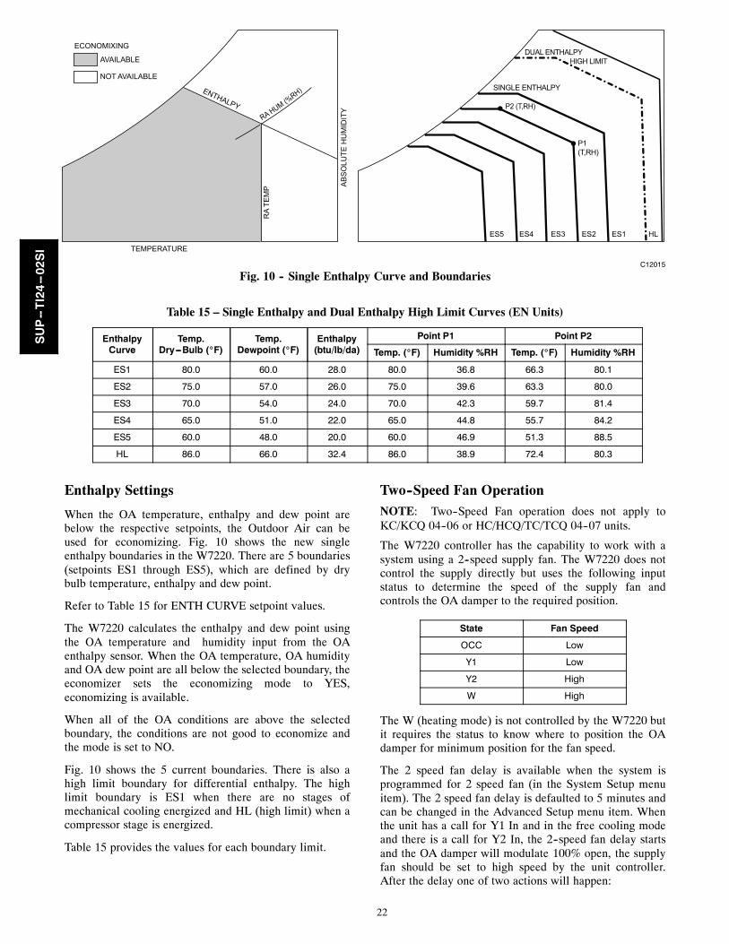
TEMPERATURE
ENTHALPY
RA
TEM
P AB
SO
LUTE
HU
MID
ITY
ECONOMIXING
AVAILABLE
NOT AVAILABLE
ES5 ES4 ES3 ES2 ES1 HL
DUAL ENTHALPYHIGH LIMIT
SINGLE ENTHALPY
P2 (T,RH)
P1(T,RH)
RA HUM (%RH)
C12015
Fig. 10 -- Single Enthalpy Curve and Boundaries
Table 15 – Single Enthalpy and Dual Enthalpy High Limit Curves (EN Units)
EnthalpyCurve
Temp.Dry---Bulb (_F)
Temp.Dewpoint (_F)
Enthalpy(btu/lb/da)
Point P1 Point P2
Temp. (_F) Humidity %RH Temp. (_F) Humidity %RH
ES1 80.0 60.0 28.0 80.0 36.8 66.3 80.1
ES2 75.0 57.0 26.0 75.0 39.6 63.3 80.0
ES3 70.0 54.0 24.0 70.0 42.3 59.7 81.4
ES4 65.0 51.0 22.0 65.0 44.8 55.7 84.2
ES5 60.0 48.0 20.0 60.0 46.9 51.3 88.5
HL 86.0 66.0 32.4 86.0 38.9 72.4 80.3
Enthalpy Settings
When the OA temperature, enthalpy and dew point arebelow the respective setpoints, the Outdoor Air can beused for economizing. Fig. 10 shows the new singleenthalpy boundaries in the W7220. There are 5 boundaries(setpoints ES1 through ES5), which are defined by drybulb temperature, enthalpy and dew point.
Refer to Table 15 for ENTH CURVE setpoint values.
The W7220 calculates the enthalpy and dew point usingthe OA temperature and humidity input from the OAenthalpy sensor. When the OA temperature, OA humidityand OA dew point are all below the selected boundary, theeconomizer sets the economizing mode to YES,economizing is available.
When all of the OA conditions are above the selectedboundary, the conditions are not good to economize andthe mode is set to NO.
Fig. 10 shows the 5 current boundaries. There is also ahigh limit boundary for differential enthalpy. The highlimit boundary is ES1 when there are no stages ofmechanical cooling energized and HL (high limit) when acompressor stage is energized.
Table 15 provides the values for each boundary limit.
Two--Speed Fan OperationNOTE: Two--Speed Fan operation does not apply toKC/KCQ 04--06 or HC/HCQ/TC/TCQ 04--07 units.
The W7220 controller has the capability to work with asystem using a 2--speed supply fan. The W7220 does notcontrol the supply directly but uses the following inputstatus to determine the speed of the supply fan andcontrols the OA damper to the required position.
State Fan Speed
OCC Low
Y1 Low
Y2 High
W High
The W (heating mode) is not controlled by the W7220 butit requires the status to know where to position the OAdamper for minimum position for the fan speed.
The 2 speed fan delay is available when the system isprogrammed for 2 speed fan (in the System Setup menuitem). The 2 speed fan delay is defaulted to 5 minutes andcan be changed in the Advanced Setup menu item. Whenthe unit has a call for Y1 In and in the free cooling modeand there is a call for Y2 In, the 2--speed fan delay startsand the OA damper will modulate 100% open, the supplyfan should be set to high speed by the unit controller.After the delay one of two actions will happen:
SUP--TI24--02SI
23
S The Y2 In call will be satisfied with the damper 100%open and fan on high speed and the call will turn off
OR
S If the call for additional cooling in the space has notbeen satisfied then the first stage of mechanical coolingwill be enabled through Y1 Out or Y2 Out.
CHECKOUT
Inspect all wiring connections at the Economizer module’sterminals, and verify compliance with the installationwiring diagrams.
For checkout, review the Status of each configuredparameter and perform the Checkout tests.
NOTE: See “Interface Overview” on page 11. forinformation about menu navigation and use of the keypad.
ELECTRICAL SHOCK HAZARD
Failure to follow this warning could cause personalinjury, death or property damage.
Before performing service or maintenance operationson unit, always turn off main power switch to unit andinstall lock(s) and lockout tag(s). Unit may have morethan one power switch. Ensure electrical service torooftop unit agrees with voltage an amperage listed onthe unit rating plate.
If any wiring changes are required, first be sure toremove power from the Economizer module beforestarting work. Pay particular attention to verifying thepower connection (24 Vac).
! WARNING
Power Up
After the W7220 module is mounted and wired, applypower.
Initial Menu Display
On initial start up, Honeywell displays on the first lineand Economizer W7220 on the second line. After a briefpause, the revision of the software appears on the first lineand the second line will be blank.
Power Loss (Outage or Brownout)
All setpoints and advanced settings are restoreda after anypower loss or interruption.a All settings are stored in non---volatile flash memory.
Status
Use the Status menu (see Table 5) to check the parametervalues for the various devices and sensors configured.
NOTE: See “Interface Overview” on page 11. forinformation about menu navigation and use of the keypad.
Checkout Tests
Use the Checkout menu (on page 16) to test the damperoperation and any configured outputs. Only items that areconfigured are shown in the Checkout menu.
NOTE: See “Interface Overview” on page 11. forinformation about menu navigation and use of the keypad.
To perform a Checkout test:
1. Scroll to the desired test in the Checkout menu usingthe the and buttons.
2. Press the button to select the item.3. RUN? appears.4. Press the button to start the test.5. The unit pauses and then displays IN PROGRESS.6. When the test is complete, DONE appears.7. When all desired parameters have been tested, press
the (Menu up) button to end the test.
The Checkout tests can all be performed at the time ofinstallation or at any time during the operation of thesystem as a test that the system is operable.
EQUIPMENT DAMAGE HAZARD
Failure to follow this caution may result in equipmentdamage.
Be sure to allow enough time for compressor startupand shutdown between checkout tests so that you donot short--cycle the compressors.
CAUTION!
SUP--TI24--02SI
24
TROUBLESHOOTING
Alarms
The Economizer module provides alarm messages thatdisplay on the 2--line LCD.
NOTE: Upon power up, the module waits 60 minutesbefore checking for alarms. This allows time for all theconfigured devices (e.g. sensors, actuator) to becomeoperational. The exception is the SAT sensor which willalarm immediately.
If one or more alarms are present and there has been nokeypad activity for at least 5 minutes, the Alarms menudisplays and cycles through the active alarms.
You can also navigate to the Alarms menu at any time.
Clearing Alarms
Once the alarm has been identified and the cause has beenremoved (e.g. replaced faulty sensor). the alarm can becleared from the display.
To clear an alarm, perform the following:
1. Navigate to the desired alarm.2. Press the button.3. ERASE? displays.4. Press the button.5. ALARM ERASED displays.6. Press the (Menu up/Exit) button to complete the
action and return to the previous menu.NOTE: If the alarm still exists after you clear it, it isredisplayed within 5 seconds.
Copyright 2014 Carrier Corp. D 7310 W. Morris St. D Indianapolis, IN 46231 Edition Date: 1214
Manufacturer reserves the right to change, at any time, specifications and designs without notice and without obligations.
Catalog No: SUP---TI24---02SI
Replaces: SUP---TI24---01SI
SUP--TI24--02SI


