Embed Size (px)
Citation preview
1
Laboratoire de Transfert de Chaleur et de Masse
ECOLE POLYTECHNIQUEFEDERALE DE LAUSANNE
Laboratoire de Transfert de Chaleur et de Masse
ECOLE POLYTECHNIQUEFEDERALE DE LAUSANNE
• Flow patterns during intube evaporation.• Description of vertical tube flow boiling design
methods.• Description of older horizontal tube flow boiling
design methods.• New Kattan-Thome-Favrat flow pattern based
flow boiling heat transfer model.• Evaporation of zeotropic mixtures.

2
Laboratoire de Transfert de Chaleur et de Masse
ECOLE POLYTECHNIQUEFEDERALE DE LAUSANNE
Figure 10.1
Laboratoire de Transfert de Chaleur et de Masse
ECOLE POLYTECHNIQUEFEDERALE DE LAUSANNE
Figure 10.2

3
Laboratoire de Transfert de Chaleur et de Masse
ECOLE POLYTECHNIQUEFEDERALE DE LAUSANNE
( )satwalltp TT
q−
=α
( ) ( )[ ] nncb
nnbtp
1ααα +=
XXXXXXFigure 9.3
Laboratoire de Transfert de Chaleur et de Masse
ECOLE POLYTECHNIQUEFEDERALE DE LAUSANNE
In nucleate pool boiling, heat transfer is a strong function of heat flux, αnb ∝ q0.7;
In forced convective evaporation, heat transfer is independent of heat flux but isdependent on the local vapor quality and mass velocity.
Nucleate boiling tends to be dominant at low vapor qualities and high heat fluxeswhile convection tends to dominate at high vapor qualities and mass velocities andlow heat fluxes. For intermediate conditions, both mechanisms are often important.
The nucleate boiling coefficient αnb is determined utilizing a nucleate pool boilingcorrelation from the literature or by proposing a new nucleate boiling term as partof the flow boiling correlation.
The convective heat transfer coefficient αcb is typically related to what is sometimesreferred to as the liquid only heat transfer coefficient αL, which is determined with asingle-phase turbulent flow heat transfer correlation, usually that of Dittus-Boelter(1930). These methods normally assume that the liquid fraction flowing in thechannel, m& (1-x), occupies the entire cross-section of the channel in the calculation ofαL.

4
Laboratoire de Transfert de Chaleur et de Masse
ECOLE POLYTECHNIQUEFEDERALE DE LAUSANNE
Chen (1963, 1966) proposed the first flow boiling correlation for evaporation in verticaltubes to attain widespread use. He envisioned the local two-phase flow boiling coefficientαtp to be the sum of the nucleate boiling contribution αnb and the convective contributionαcb:
cbnbtp α+α=α [10.3.1]
He surmised that the steeper temperature gradient in the liquid near the tube wall underforced convection conditions, relative to that in nucleate pool boiling, partially suppressednucleation of boiling sites and hence reduced the contribution of nucleate boiling. On theother hand, he noted that the vapor formed by the evaporation process increased the liquidvelocity and hence the convective heat transfer contribution tends to be increased relativeto that of single-phase flow of the liquid. Hence, he formulated the following expression toaccount for these two effects:
FS LFZtp α+α=α [10.3.2]
Laboratoire de Transfert de Chaleur et de Masse
ECOLE POLYTECHNIQUEFEDERALE DE LAUSANNE
• the nucleate pool boiling correlation of Forster and Zuber (1955) is used tocalculate the nucleate boiling heat transfer coefficient, αFZ;
• the nucleate boiling suppression factor acting on αFZ is S;• the turbulent flow correlation of Dittus-Boelter (1930) for tubular flows is used to
calculate the liquid-phase convective heat transfer coefficient, αL;• and the increase in the liquid-phase convection due to the two-phase flow is given
by his two-phase multiplier F.
The Forster-Zuber correlation gives the nucleate pool boiling coefficient as:
75.0sat
24.0sat24.0
G24.029.0
L5.0
49.0L
45.0pL
79.0L
FZ pTh
ck00122.0
LG
ΔΔ⎥⎥⎦
⎤
⎢⎢⎣
⎡
ρμσ
ρ=α [10.3.3]
where the wall superheat ΔTsat is the local temperature difference between the inner tubewall (Twall) and the local saturation temperature (Tsat), such that ΔTsat = (Twall - Tsat). Thepressure difference Δpsat is obtained from the vapor pressures of the fluid at the walltemperature (pwall) and at the saturation temperature (psat), such that Δpsat = (pwall - psat). Inthis expression, Δpsat is in the units of N/m2.

5
Laboratoire de Transfert de Chaleur et de Masse
ECOLE POLYTECHNIQUEFEDERALE DE LAUSANNE
The liquid-phase convective heat transfer coefficient αL is given by the Dittus-Boelter (1930) correlation for the fraction of liquid flowing alone in a tube ofinternal diameter di, i.e. using a mass velocity of m& (1-x), as:
⎟⎟⎠
⎞⎜⎜⎝
⎛=α
i
L4.0L
8.0LL d
kPrRe023.0 [10.3.4]
where the liquid Reynolds number ReL is: L
iL
d)x1(mReμ−
=&
[10.3.5]
and x is the local vapor quality and m& is the total mass velocity of the liquid plusvapor in the tube of internal diameter di. PrL is the liquid Prandtl number defined as:
L
LpLL k
cPr
μ= [10.3.6]
The two-phase multiplier F of Chen is: 736.0
tt213.0
X1F ⎟⎟
⎠
⎞⎜⎜⎝
⎛+= [10.3.7]
where the Martinelli parameter Xtt is used for the two-phase effect on convection,where Xtt is defined as:
1.0
G
L
5.0
L
G9.0
tt xx1X ⎟⎟
⎠
⎞⎜⎜⎝
⎛μμ
⎟⎟⎠
⎞⎜⎜⎝
⎛ρρ
⎟⎠⎞
⎜⎝⎛ −
= [10.3.8]
Laboratoire de Transfert de Chaleur et de Masse
ECOLE POLYTECHNIQUEFEDERALE DE LAUSANNE
Note, however, that when 1/Xtt ≤ 0.1, F is set equal to 1.0. The Chen boiling suppressionfactor S is
17.1tpRe00000253.01
1S+
= [10.3.9]
This in turn is a function of his two-phase Reynolds number:
25.1Ltp FReRe = [10.3.10]
His fluid database included water in upflow and downflow (pressures from 0.55 to 34.8bar) and methanol, cyclohexane, n-pentane, n-heptane and benzene, all in upflow at 1 bar.Most of the data were at low vapor qualities but the entire range covers values from 0.01to 0.71. His correlation is applicable as long as the heated wall remains wet, i.e. up to theonset of dryout. Since the wall superheat ΔTsat is typically not known, an iterativecalculation involving Twall and pwall is required when the heat flux q is specified.

6
Laboratoire de Transfert de Chaleur et de Masse
ECOLE POLYTECHNIQUEFEDERALE DE LAUSANNE
Example 1: Determine the local flow boiling heat transfer coefficient for the followingsituation at a local vapor quality of 0.5. Refrigerant R-134a is evaporating inside a vertical, plain tube whose internal diameter is 20 mm. R-134a is at its saturation temperature of 4°C (3.377 bar), flowing at 0.09425 kg s-1. The tube wall is at 10°C. Solution: The physical properties of R-134a at 4°C are: ρL = 1281 kg m-3; ρG = 16.56 kg m-
3; μL = 0.0002576 Ns m-2; μG = 0.0000109 Ns m-2; hLG = 195500 J kg-1; kL = 0.0902 W m-1
K-1; cpL = 1352 J kg-1 K-1; σ = 0.011 N m-1; PrL = cpLμL/kL =3.861; psat = 414600 N m-2 at 10°C; psat = 337700 N m-2 at 4°C. The mass velocity is 300 kg m-2 s-1 and thus the liquid only Reynolds number is:
( ) ( )( ) 116460002576.0
020.05.01300dx1mReL
iL =
−=
μ−
=&
Applying Dittus-Boelter: ( ) ( ) 124.08.0L KmW8.318
020.00902.0861.311646023.0 −−=⎟
⎠⎞
⎜⎝⎛=α
Laboratoire de Transfert de Chaleur et de Masse
ECOLE POLYTECHNIQUEFEDERALE DE LAUSANNE
The Martinelli parameter is:
1560.00000109.00002576.0
128156.16
5.05.01X
1.05.09.0
tt =⎟⎠⎞
⎜⎝⎛
⎟⎠⎞
⎜⎝⎛
⎟⎠⎞
⎜⎝⎛ −
=
The two-phase multiplier is: 021.4213.0156.01F
736.0
=⎟⎠⎞
⎜⎝⎛ +=
The two-phase Reynolds number is then: ( ) 66312021.411646Re 25.1tp ==
The boiling suppression factor is: ( )
4745.06631200000253.01
1S 17.1 =+
=

7
Laboratoire de Transfert de Chaleur et de Masse
ECOLE POLYTECHNIQUEFEDERALE DE LAUSANNE
The nucleate boiling heat transfer coefficient for the wall superheat of 6 K is:
( ) ( ) ( )( ) ( ) ( ) ( )
( ) ( )
12FZ
75.024.024.024.029.05.0
49.045.079.0
FZ
KmW2.3173
33770041460041056.161955000002576.0011.0
128113520902.000122.0
−−=α
−−⎥⎥⎦
⎤
⎢⎢⎣
⎡=α
Finally, the local heat transfer coefficient is:
( ) ( ) 12tp KmW6.27879.12817.1505021.48.3184745.02.3173 −−=+=+=α
Thus, the nucleate boiling and convective boiling contributions represent 54% and 46%,respectively, of the local heat transfer coefficient under these conditions. The local heat flux iscalculated from αtp and ΔTsat to be 16725.6 W m-2.
Laboratoire de Transfert de Chaleur et de Masse
ECOLE POLYTECHNIQUEFEDERALE DE LAUSANNE
Shah (1982) proposed equations to implement his chart calculation method heproposed earlier. While he considered nucleate boiling and convective boiling to be thetwo important heat transfer mechanisms similar to Chen (1963, 1966), his methodinstead chooses the larger of the two, that is the larger of his nucleate boilingcoefficient αnb and his convective boiling coefficient αcb, for the value of local two-phase flow boiling heat transfer coefficient αtp. He proposed a method applicable toboth vertical tubes and horizontal tubes. His vertical tube method is presented here,which begins by defining a dimensionless parameter N, which for vertical tubes at allvalues of the liquid Froude number FrL is:
0CN = [10.3.11]
and his factor Co is determined from the local vapor quality and density ratio as:
5.0
L
G8.0
0 xx1C ⎟⎟
⎠
⎞⎜⎜⎝
⎛ρρ
⎟⎠⎞
⎜⎝⎛ −
= [10.3.12]
while the liquid Froude number is defined as: i
2L
2
L gdmFr
ρ=
&[10.3.13]

8
Laboratoire de Transfert de Chaleur et de Masse
ECOLE POLYTECHNIQUEFEDERALE DE LAUSANNE
To characterize convection, the liquid-phase convective heat transfer coefficient αL isdetermined from the liquid fraction of the flow, m& (1-x), using the Dittus-Boelter (1930)correlation given in [10.3.4]. His convective boiling heat transfer coefficient αcb iscalculated as:
8.0L
cb
N8.1
=αα [10.3.14]
The effect of heat flux on nucleate boiling is characterized by the Boiling number, Bo,which is defined as:
LGhmqBo
&= [10.3.15]
representing the ratio of the actual heat flux to the maximum heat flux achievable bycomplete evaporation of the liquid.
Laboratoire de Transfert de Chaleur et de Masse
ECOLE POLYTECHNIQUEFEDERALE DE LAUSANNE
His parameter N is used to determine the appropriate set of equations to use as follows:
When N > 1.0 and Bo > 0.0003. αnb is calculated as below: 5.0
L
nb Bo230=αα [10.3.16]
When N > 1.0 and Bo < 0.0003. αnb is calculated as below: 5.0
L
nb Bo461 +=αα [10.3.17]
When 1.0 > N > 0.1. αnb is calculated as below:
( )1.0N74.2expBoF 5.0S
L
nb −=αα [10.3.18]
When N < 0.1. αnb in the bubble suppression regime is calculated using the equation below:
( )15.0N74.2expBoF 5.0S
L
nb −=αα [10.3.19]
9
Laboratoire de Transfert de Chaleur et de Masse
ECOLE POLYTECHNIQUEFEDERALE DE LAUSANNE
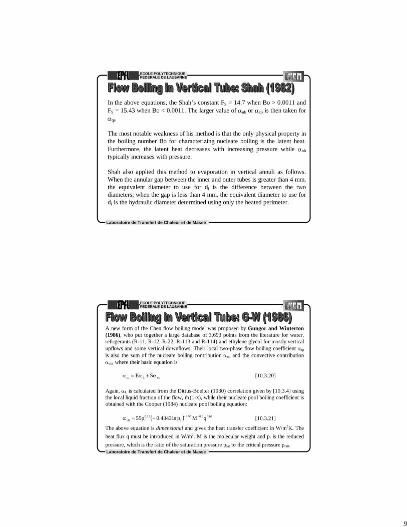
In the above equations, the Shah’s constant FS = 14.7 when Bo > 0.0011 andFS = 15.43 when Bo < 0.0011. The larger value of αnb or αcb is then taken forαtp.
The most notable weakness of his method is that the only physical property inthe boiling number Bo for characterizing nucleate boiling is the latent heat.Furthermore, the latent heat decreases with increasing pressure while αnbtypically increases with pressure.
Shah also applied this method to evaporation in vertical annuli as follows.When the annular gap between the inner and outer tubes is greater than 4 mm,the equivalent diameter to use for di is the difference between the twodiameters; when the gap is less than 4 mm, the equivalent diameter to use fordi is the hydraulic diameter determined using only the heated perimeter.
Laboratoire de Transfert de Chaleur et de Masse
ECOLE POLYTECHNIQUEFEDERALE DE LAUSANNE
A new form of the Chen flow boiling model was proposed by Gungor and Winterton(1986), who put together a large database of 3,693 points from the literature for water,refrigerants (R-11, R-12, R-22, R-113 and R-114) and ethylene glycol for mostly verticalupflows and some vertical downflows. Their local two-phase flow boiling coefficient αtp
is also the sum of the nucleate boiling contribution αnb and the convective contributionαcb, where their basic equation is
nbLtp SE α+α=α [10.3.20]
Again, αL is calculated from the Dittus-Boelter (1930) correlation given by [10.3.4] usingthe local liquid fraction of the flow, m& (1-x), while their nucleate pool boiling coefficient isobtained with the Cooper (1984) nucleate pool boiling equation:
( ) 67.05.055.0r
12.0rnb qMpln4343.0p55 −−−=α [10.3.21]
The above equation is dimensional and gives the heat transfer coefficient in W/m2K. Theheat flux q must be introduced in W/m2. M is the molecular weight and pr is the reducedpressure, which is the ratio of the saturation pressure psat to the critical pressure pcrit.
10
Laboratoire de Transfert de Chaleur et de Masse
ECOLE POLYTECHNIQUEFEDERALE DE LAUSANNE
Their two-phase convection multiplier E is a function of the Martinelli parameter and alsothe heat flux via the Boiling number:
86.0
tt
16.1
X137.1Bo240001E ⎟⎟
⎠
⎞⎜⎜⎝
⎛++= [10.3.22]
where Xtt and Bo have been defined earlier. Their boiling suppression factor S is
[ ] 117.1L
2 ReE00000115.01S −+= [10.3.23]
with ReL based on m& (1-x). Compared to their database, this method gave a meandeviation of ±21.4% compared to ±57.7% for the Chen (1963, 1966) correlation and±21.9% for the Shah (1982) correlation. Hence, as the Shah correlation was notdeveloped using this database, this comparison gives a good independent credibility of itsaccuracy. Using the same equivalent diameter definitions as Shah above, Gungor andWinterton predicted evaporation in vertical annuli to a mean error of ±29.4%.
Laboratoire de Transfert de Chaleur et de Masse
ECOLE POLYTECHNIQUEFEDERALE DE LAUSANNE
Gungor and Winterton (1987) a year later proposed a newer, simplerversion of this correlation based only on convective boiling:
Lnewtp E α=α [10.3.24]
Their new two-phase convection multiplier Enew is:
41.0
V
L75.0
86.0new x1
x12.1Bo30001E ⎟⎟⎠
⎞⎜⎜⎝
⎛ρρ
⎟⎠⎞
⎜⎝⎛
−++= [10.3.25]
where Bo has been defined earlier and αL is calculated as before. Theaccuracy was similar to their earlier correlation and this version has beenrecommended in Thome (1997) as the better of the two compared to flowboiling data for R-134a.

11
Laboratoire de Transfert de Chaleur et de Masse
ECOLE POLYTECHNIQUEFEDERALE DE LAUSANNE
Example 2: Considering the same conditions as in Example 1, determine the local flowboiling heat transfer coefficient at a local vapor quality of 0.5 for a heat flux of 16725.6W m-2. The molecular weight of R-134a is 102.03 and the critical pressure is 40.59 bar.
Solution: The reduced pressure is pr = 3.377/40.59 = 0.08320. The Boiling number iscalculated as:
0002852.0(195500)300
16725.6hmqBo
LG===
&
The convection enhancement factor E is:
625.91560.0137.1)0002852.0(240001E
86.016.1 =⎟
⎠⎞
⎜⎝⎛++=
The boiling suppression factor is:
[ ] 1410.0)11646()625.9(00000115.01S117.12 =+=
−
Laboratoire de Transfert de Chaleur et de Masse
ECOLE POLYTECHNIQUEFEDERALE DE LAUSANNE
The nucleate boiling coefficient is:
( ) 267.05.055.012.0nb mW5.2616)16725.6()03.102(0.08320ln4343.0)0.08320(55 −−− =−=α
In Example 1, αL is equal to 318.8 W m-2 K-1. Thus, the local flow boiling coefficient accordingto Gungor and Winterton is:
12tp KmW4.34379.3685.3068)5.2616(1410.0)8.318(625.9 −−=+=+=α
Thus, the nucleate boiling and convective boiling contributions represent 11% and 89%,respectively, of the local heat transfer coefficient under these conditions, i.e. dramaticallydifferent that predicted by the Chen method. The local wall superheat is calculated from αtp and qto be 4.87 K as opposed to 6 K in the Chen example.

12
Laboratoire de Transfert de Chaleur et de Masse
ECOLE POLYTECHNIQUEFEDERALE DE LAUSANNE
Steiner-Taborek Asymptotic Model
Natural limitations to flow boiling coefficients. Before presenting a newprediction method, Steiner and Taborek (1992) stated that the following limitsshould apply to evaporation in vertical tubes:
• For heat fluxes below the threshold for the onset of nucleate boiling (q <qONB), only the convective contribution should be counted and not thenucleate boiling contribution.
• At large heat fluxes, the nucleate boiling contribution should dominate.• When x = 0, αtp should be equal to the single-phase liquid convective heat
transfer coefficient when q < qONB but αtp should correspond to that plusαnb when q > qONB.
• When x = 1.0, αtp should equal the vapor-phase convective coefficient αGt(the forced convection coefficient with the total flow as vapor), assumingno liquid mist still exists in the flow at these conditions.
Laboratoire de Transfert de Chaleur et de Masse
ECOLE POLYTECHNIQUEFEDERALE DE LAUSANNE
Region A-B: Before point A, only single-phase convection to the subcooledliquid occurs. Between points A and B, only liquid-phase convection occurs if q< qONB while subcooled boiling occurs if q > qONB. In subcooled boiling, bubblesgrow and collapse near the tube wall, which increases heat transfer.Region B-C-D: When q < qONB, only convective evaporation occurs asindicated by the “pure convective boiling” curve. When q > qONB, both nucleateand convective boiling contributions are present and are superimposed. Thehorizontal dashed lines are the nucleate boiling coefficient at the particular heatflux. The solid curves are the superimposed contribution of nucleate boiling andconvective boiling, that is αtp. The flow pattern passes through the bubbly flowand churn flow regimes as shown in the bottom diagram.Region D-E-F. When q < qONB, the process continues along the “pureconvective boiling” curve up to the onset of dryout at high vapor qualitiesapproaching 1.0. When q > qONB, the annular flow regime is reached,characterized by a thin turbulent annular liquid layer on the tube wall and acentral vapor core, and continues up to the critical vapor quality xcrit reachedwhere the annular film dries out.Region F-G. At xcrit the liquid film becomes unstable due to interfacial shearand adhesion forces. In the mist flow regime, the heat transfer mechanismschange completely, where heat is now transferred by vapor-phase convection,by evaporation of the entrained liquid droplets within the superheated vapor, byimpingement of droplets on the wall and by radiation. (Note: the Steiner-Taborek model does not predict the dashed lines of the mist flow regime when x> xcrit).
Figure 10.4

13
Laboratoire de Transfert de Chaleur et de Masse
ECOLE POLYTECHNIQUEFEDERALE DE LAUSANNE
Flow boiling model. Based on the above premises, Steiner and Taborek (1992) proposed acomprehensive evaporation model for vertical tubes. Their local flow boiling coefficient is obtainedfrom an asymptotic approach using an exponent n equal to 3 as:
( ) ( )[ ] 3/13tpLt
3nbo,nbtp FF α+α=α [10.3.26]
In this expression, the parameters are as follows:
• αnb,o is the local nucleate pool boiling coefficient at a reference heat flux qo at the reducedpressure pr equal to 0.1;
• Fnb is the nucleate boiling correction factor (but is not a boiling suppression factor, which is notrequired in an asymptotic model);
• αLt is the local liquid-phase forced convection coefficient based on the total flow as liquid (noton the liquid fraction of the flow as in the above methods) and is obtained with the Gnielinski(1976) correlation and not the Dittus-Boelter (1930) correlation;
• Ftp is the two-phase multiplier that accounts for enhancement of liquid convection by the highervelocity of a two-phase flow compared to single-phase flow of the liquid in the channel.
Laboratoire de Transfert de Chaleur et de Masse
ECOLE POLYTECHNIQUEFEDERALE DE LAUSANNE
The Gnielinski correlation for obtaining αLt is:
( )( )( ) ( )1Pr8/7.121
Pr1000Re8/k
d3/2
L2/1
L
LLtL
L
iLt
−ƒ+−ƒ
=α
[10.3.27]
The Fanning friction factor, ƒL, for the liquid is:
( )[ ] 2LtL 64.1Reln7904.0 −−=ƒ [10.3.28]
This expression is valid when 4000 < ReLt < 5000000 and 0.5 < PrL < 2000 for single-phaseflows. The total mass velocity of liquid plus vapor is used for evaluating the liquid Reynoldsnumber, so that ReLt is:
L
iLt
dmReμ
=&
[10.3.29]
14
Laboratoire de Transfert de Chaleur et de Masse
ECOLE POLYTECHNIQUEFEDERALE DE LAUSANNE
The two-phase multiplier Ftp is for convective evaporation, which will occur if x < xcrit and q >qONB or over the entire range of x if q < qONB. For applications where x < xcrit at the tube exit andq > qONB, such as power boilers and thermosyphon reboilers, the following equation is used:
( )1.135.0
G
L6.05.1tp x9.1x1F
⎥⎥⎦
⎤
⎢⎢⎣
⎡⎟⎟⎠
⎞⎜⎜⎝
⎛ρρ
+−= [10.3.30]
This expression covers (ρL/ρG) from 3.75 to 5000 and converges to 1.0 as x goes to 0. xcrit isoften assumed to occur at about 0.5 for these applications. When q < qONB, only pure convectiveevaporation is present, extending from x = 0.0 to x = 1.0. At the limiting case at x = 1.0, thevalue of αtp corresponds to αGt, which is the forced convection coefficient with the total flow asall vapor. The Gnielinski correlation is also used for obtaining αGt:
( )( )( ) ( )1Pr8/7.121
Pr1000Re8/k
d3/2
G2/1
GGt
G
iGt
−ƒ+−ƒ
=α
[10.3.31]
The Fanning friction factor for the vapor, ƒG, is: ( )[ ] 2GtG 64.1Reln7904.0 −−=ƒ [10.3.32]
Laboratoire de Transfert de Chaleur et de Masse
ECOLE POLYTECHNIQUEFEDERALE DE LAUSANNE
The total mass velocity of liquid plus vapor is used for evaluating the vapor Reynolds number, sothat ReGt is:
G
iGt
dmReμ
=&
[10.3.33]
For this case, the following expression is used for Ftp:
( ) ( ) ( )( )267.0
G
L7.001.0
L
G
2.235.0
G
L01.06.05.1tp x181xx1x9.1x1F
−−−
⎪⎭
⎪⎬⎫
⎪⎩
⎪⎨⎧
⎥⎥⎦
⎤
⎢⎢⎣
⎡⎟⎟⎠
⎞⎜⎜⎝
⎛ρρ
−+⎟⎟⎠
⎞⎜⎜⎝
⎛αα
+⎥⎥⎦
⎤
⎢⎢⎣
⎡⎟⎟⎠
⎞⎜⎜⎝
⎛ρρ
−+−=
[10.3.34]
This expression covers fluids with values of (ρL/ρG) from 3.75 to 1017. The terms with exponentsof 0.01 make this expression go to its proper limits at x = 0 and x = 1.

15
Laboratoire de Transfert de Chaleur et de Masse
ECOLE POLYTECHNIQUEFEDERALE DE LAUSANNE
The minimum heat flux for determining the onset of nucleate boiling qONB is given by the followingexpression using the liquid-phase heat transfer coefficient αLt:
LGGo
LtsatONB hr
T2qρ
ασ= [10.3.35]
In this expression, σ is the surface tension, Tsat is the saturation temperature in Kelvin, ro is thecritical nucleation radius for a boiling site in meters and hLG is the latent heat of vaporization. Therecommended value for ro is 0.3 x 10⁻⁶ m. For q > qONB, nucleate boiling is present in the flowboiling process but below this threshold it is not.
Laboratoire de Transfert de Chaleur et de Masse
ECOLE POLYTECHNIQUEFEDERALE DE LAUSANNE
The nucleate boiling coefficient αnb is determined here with a method similar to the nucleatepool boiling method of Gorenflo (1993) but the method below is not exactly the same. Thestandard nucleate boiling coefficients for the Steiner-Taborek flow boiling correlation αnb,o aregiven in Table 10.1 at the following standard conditions: a reduced pressure of pr = 0.1, a meansurface roughness of Rp,o = 1 μm and the heat flux qo equal to the value listed for each fluid.The nucleate boiling correction factor Fnb includes the effects of reduced pressure, heat flux,tube diameter, surface roughness and a residual molecular weight correction factor on αnb,o asfollows:
( )MFRR
dd
qqFF
133.0
o,p
p4.0
o,i
i
nf
opfnb ⎟
⎟⎠
⎞⎜⎜⎝
⎛⎟⎟⎠
⎞⎜⎜⎝
⎛⎟⎟⎠
⎞⎜⎜⎝
⎛=
−
[10.3.36]
The pressure correction factor Fpf, valid for pr < 0.95, accounts for the increase in the nucleateboiling coefficient with increasing pressure:
7.3r7
r
45.0rpf p
p17.14.3p816.2F
⎪⎭
⎪⎬⎫
⎪⎩
⎪⎨⎧
⎥⎦
⎤⎢⎣
⎡
−++= [10.3.37]
The nucleate boiling exponent, nf, on the normalized heat flux term is:
( )rp75.1exp1.08.0nf −= [10.3.38]

16
Laboratoire de Transfert de Chaleur et de Masse
ECOLE POLYTECHNIQUEFEDERALE DE LAUSANNE
The above expression is for all fluids except cryogens (nitrogen, oxygen, etc.), where it is
( )rp105.1exp13.07.0nf −= [10.3.39]
The standard tube reference diameter di,o is 0.01 m, i.e. 10 mm. The standard value of the surfaceroughness is Rp,o = 1 μm (typical of industrial tubes and the default value if Rp is unknown) andthe surface roughness term covers values of Rp from 0.1 to 18 μm. The residual molecular weightcorrection factor is in terms of the liquid molecular weight M (valid for 10 < M < 187):
( ) ( ) 2M000028427.0Mln199.0377.0MF ++= [10.3.40]
The maximum value of F(M) is 2.5, even when the expression gives a larger value. For cryogenicliquids H2 and He, the values of F(M) are specifically 0.35 and 0.86, respectively.
Their method is based on an extensive database containing 10,262 data points for water and anadditional 2345 data points for four refrigerants (R-11, R-12, R-22 and R-113), sevenhydrocarbons (benzene, n-pentane, n-heptane, cyclo-hexane, methanol, ethanol and n-butanol),three cryogens (nitrogen, hydrogen and helium) and ammonia. It is currently regarded as the mostaccurate vertical tube boiling correlation available for pure fluids. However, it is difficult toextend its use to mixtures since no simple way to determine the values of αnb,o for mixtures.
Laboratoire de Transfert de Chaleur et de Masse
ECOLE POLYTECHNIQUEFEDERALE DE LAUSANNE
Table 10.1. Standard nucleate flowboiling coefficients of Steiner andTaborek (1992) for αnb,o in W/m2 K atpr = 0.1 for qo in W/m2 and Rp,o = 1 μmwith pcrit in bar.
Fluid pcrit M qo αnb,o
Methane 46.0 16.04 20000 8060Ethane 48.8 30.07 20000 5210Propane 42.4 44.10 20000 4000n-Butane 38.0 58.12 20000 3300n-Pentane 33.7 72.15 20000 3070Isopentane 33.3 72.15 20000 2940n-Hexane 29.7 86.18 20000 2840n-Heptane 27.3 100.2 20000 2420Cyclohexane 40.8 84.16 20000 2420Benzene 48.9 78.11 20000 2730Toluene 41.1 92.14 20000 2910Diphenyl 38.5 154.2 20000 2030Methanol 81.0 32.04 20000 2770Ethanol 63.8 46.07 20000 3690n-Propanol 51.7 60.10 20000 3170Isopropanol 47.6 60.10 20000 2920n-Butanol 49.6 74.12 20000 2750Isobutanol 43.0 74.12 20000 2940Acetone 47.0 58.08 20000 3270R-11 44.0 137.4 20000 2690R-12 41.6 120.9 20000 3290R-13 38.6 104.5 20000 3910R-13B1 39.8 148.9 20000 3380R-22 49.9 86.47 20000 3930R-23 48.7 70.02 20000 4870R-113 34.1 187.4 20000 2180R-114 32.6 170.9 20000 2460R-115 31.3 154.5 20000 2890R-123 36.7 152.9 20000 2600R-134a 40.6 102.0 20000 3500R-152a 45.2 66.05 20000 4000R-226 30.6 186.5 20000 3700R-227 29.3 170.0 20000 3800RC318 28.0 200.0 20000 2710R-502 40.8 111.6 20000 2900Chloromethane 66.8 50.49 20000 4790Tetrachloromethane 45.6 153.8 20000 2320Tetrafluoromethane 37.4 88.00 20000 4500Helium I £ 2.275 4.0 1000 1990Hydrogen (para) 12.97 2.02 10000 12220Neon 26.5 20.18 10000 8920Nitrogen 34.0 28.02 10000 4380Argon 49.0 39.95 10000 3870Oxygen 50.8 32.00 10000 4120Water 220.6 18.02 150000 25580Ammonia 113.0 17.03 150000 36640

17
Laboratoire de Transfert de Chaleur et de Masse
ECOLE POLYTECHNIQUEFEDERALE DE LAUSANNE
Example 3: Considering the same conditions as in Examples 1 and 2, determine thelocal flow boiling heat transfer coefficient for the following situation at a local vaporquality of 0.5 for a heat flux of 16725.6 W m-2. Assume a surface roughness of 2 μm. Solution: For R-134a the standard nucleate flow boiling coefficient αnb,o = 3500 W m-2
K-1 at pr = 0.1 for qo = 20000 W m-2 and Rp,o = 1 μm. The properties are: ρL = 1281 kg m-3; ρG = 16.56 kg m-3; μL = 0.0002576 Ns m-2; μG = 0.0000109 Ns m-2; hLG = 195500 J kg-1; kL = 0.0902 W m-1 K-1; cpL = 1352 J kg-1 K-1; σ = 0.011 N m-1; M = 102.03; PrL = cpLμL/kL =3.861; pr = 0.08320. The mass velocity is 300 kg m-2 s-1 and thus the liquid Reynolds number is:
( ) 232920002576.0
020.0300dmReL
iL ==
μ=&
The Fanning friction factor, ƒ, is:
( )[ ] 02513.064.123292ln7904.0 2 =−=ƒ −
Laboratoire de Transfert de Chaleur et de Masse
ECOLE POLYTECHNIQUEFEDERALE DE LAUSANNE
The liquid convection coefficient is:
( ) ( )( )( )( ) ( )[ ]
12Lt
3/22/1Lt
KmW7.5971861.38/02513.07.121
861.31000232928/02513.00902.0
020.0
−−=α
−+−
=α
The two-phase multiplier is calculated:
( ) 304.756.16
1281)5.0(9.15.01F1.135.0
6.05.1tp =
⎥⎥⎦
⎤
⎢⎢⎣
⎡⎟⎠⎞
⎜⎝⎛+−=
The minimum heat flux qONB for onset of nucleate boiling is given by:
2ONB mW3752
)195500)(56.16(0000003.0)7.597)(415.273)(011.0(2q −=
+=
where ro = 0.3 x 10⁻⁶ m has been used for the critical nucleation radius. Since q > qONB, nucleate boiling is predicted to occur.
18
Laboratoire de Transfert de Chaleur et de Masse
ECOLE POLYTECHNIQUEFEDERALE DE LAUSANNE
The exponent on the normalized heat flux term for representing nucleate boiling is:
[ ] 6843.0)08320.0(75.1exp1.08.0nf =−=
The pressure correction factor is calculated:
9203.0)08320.0()08320.0(1
7.14.3)08320.0(816.2F 7.37
45.0pf =
⎪⎭
⎪⎬⎫
⎪⎩
⎪⎨⎧
⎥⎦
⎤⎢⎣
⎡
−++=
The residual correction factor is:
( ) ( ) 593.1)03.102(000028427.003.102ln199.0377.0MF 2 =++=
The nucleate boiling correction factor is then obtained:
( ) 078.1593.112
010.0020.0
2000016725.69203.0F
133.04.06843.0
nb =⎟⎠⎞
⎜⎝⎛
⎟⎠⎞
⎜⎝⎛
⎟⎠⎞
⎜⎝⎛=
−
Laboratoire de Transfert de Chaleur et de Masse
ECOLE POLYTECHNIQUEFEDERALE DE LAUSANNE
The local flow boiling coefficient is obtained:
( ) ( )[ ] [ ] 123/1333/133tp KmW2.5512)6.4365()3773()304.7(7.597)078.1(3500 −−=+=+=α
Thus, the local heat transfer coefficient here is predicted to be much larger than the valuesobtained with the Chen and Gungor-Winterton methods. The local wall superheat iscalculated from αtp and q to be 3.03 K.
19
Laboratoire de Transfert de Chaleur et de Masse
ECOLE POLYTECHNIQUEFEDERALE DE LAUSANNE
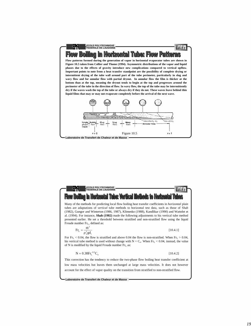
Flow patterns formed during the generation of vapor in horizontal evaporator tubes are shown inFigure 10.5 taken from Collier and Thome (1994). Asymmetric distributions of the vapor and liquidphases due to the effects of gravity introduce new complications compared to vertical upflow.Important points to note from a heat transfer standpoint are the possibility of complete drying orintermittent drying of the tube wall around part of the tube perimeter, particularly in slug andwavy flow and for annular flow with partial dryout. In annular flow the film is thicker at thebottom than at the top, meaning the dryout tends to begin at the top and progresses around theperimeter of the tube in the direction of flow. In wavy flow, the top of the tube may be intermittentlydry if the waves wash the top of the tube or always dry if they do not. These waves leave behind thinliquid films that may or may not evaporate completely before the arrival of the next wave.
Figure 10.5
Laboratoire de Transfert de Chaleur et de Masse
ECOLE POLYTECHNIQUEFEDERALE DE LAUSANNE
Many of the methods for predicting local flow boiling heat transfer coefficients in horizontal plaintubes are adaptations of vertical tube methods to horizontal test data, such as those of Shah(1982), Gungor and Winterton (1986, 1987), Klimenko (1988), Kandlikar (1990) and Wattelet etal. (1994). For instance, Shah (1982) made the following adjustments to his vertical tube methodpresented earlier. He set a threshold between stratified and non-stratified flow using the liquidFroude number FrL, defined as:
i2L
2
L gdmFr
ρ=
&[10.4.1]
For FrL < 0.04, the flow is stratified and above 0.04 the flow is non-stratified. When FrL > 0.04,his vertical tube method is used without change with N = Co. When FrL < 0.04, instead, the valueof N is modified by the liquid Froude number FrL as:
o3.0
L CFr38.0N −= [10.4.2]
This correction has the tendency to reduce the two-phase flow boiling heat transfer coefficient atlow mass velocities but leaves them unchanged at large mass velocities. It does not howeveraccount for the effect of vapor quality on the transition from stratified to non-stratified flow.
20
Laboratoire de Transfert de Chaleur et de Masse
ECOLE POLYTECHNIQUEFEDERALE DE LAUSANNE
Gungor and Winterton (1986) setting their threshold value a little higher at FrL < 0.05.When FrL > 0.05, their vertical tube method is used without change but when FrL < 0.05,their factor E is corrected as follows
( )LFr21.0L2 FrE −= [10.4.3]
Thus, thus new parameter E2 is applied as a multiplier to E in their method. Their boilingsuppression factor S, is similarly multiplied by the another correction factor
( ) 2/1L2 FrS = [10.4.4]
These two corrections have the tendency to reduce the two-phase flow boiling heattransfer coefficient at low mass velocities but leave them unchanged at large values.
Kandlikar (1990) set his stratification threshold at FrL = 0.05. Noting the difference in thetrends in their heat transfer coefficients, Wattelet et al. (1994) classified their data asannular or stratified flow and set their stratification threshold to a much larger value of FrL
= 0.25. The liquid Froude number FrL is not a reliable approach for predicting the onset ofstratification, as shown in a direct comparison to experimental flow observations forvarious refrigerants by Kattan, Thome and Favrat (1995). This threshold criterion is in factoff by as much as 10 to 16 times in numerous instances! Hence, the above methods do nottend to predict heat transfer in stratified types of flow reliably nor accurately.
Laboratoire de Transfert de Chaleur et de Masse
ECOLE POLYTECHNIQUEFEDERALE DE LAUSANNE
The methods mentioned above do tend to predict heat transfer reasonably well in theannular flow regime but their shortcomings can be summarized as follows:
• They only recognize stratified and non-stratified flows but not the different flowpatterns occurring in horizontal flow boiling, and they tend to poorly predict thethreshold from unstratified to stratified flow;
• Their local boiling coefficients plotted versus local vapor quality at a fixed heat flux q,that is a plot of αtp vs. x, often do not represent the experimental trends nor the slope;
• They do not account for the onset of dryout in annular flow at high vapor qualities andhence these methods are incapable of predicting the sharp peak in αtp vs. x found inmany experimental data sets nor do they predict the subsequent sharp decline in αtp
after the onset of dryout at the top of the tube in annular flows at high vapor qualities.Hence, they often overpredict heat transfer in this region by 100% to 300% or more;
• They attempt to model annular flow by modifying a tubular flow correlation (Dittus-Boelter) as opposed to modelling the liquid film using a film flow approach.
The foregoing flow boiling correlations therefore do not qualify as general methods,especially for stratified types of flows nor for local conditions with partial dryout on thetop perimeter of the tube. In their favor, however, these methods are comprised of a smallset of equations and are easy to quickly implement.

21
Laboratoire de Transfert de Chaleur et de Masse
ECOLE POLYTECHNIQUEFEDERALE DE LAUSANNE
Local Flow Pattern Evaporation Model of Kattan-Thome-Favrat
A more phenomenological approach, incorporating the local two-phase flowstructure as a function of the local flow pattern, has been proposed by Kattan,Thome and Favrat (1998a, 1998b, 1998c). Their method is based on theirown two-phase flow pattern map for horizontal evaporating flows (describedin the chapter on two-phase flow patterns). So far, their flow boiling modelcovers fully stratified flows, stratified-wavy flows, intermittent flows, annularflows and annular flows with partial dryout. Plug and slug flows are classifiedas intermittent flows, in which the tube wall is assumed to always remain wetby frequent passing of large amplitude waves that leave behind a liquid filmon the top of the tube. Intermittent flows have a very complex flow structureand were for simplicity modelled as annular flows with reasonable success.Similarly, annular flow with partial dryout is classified as a form of stratified-wavy flow and is modelled as such. Heat transfer in bubbly and mist flowregimes are not currently addressed in their model.
Laboratoire de Transfert de Chaleur et de Masse
ECOLE POLYTECHNIQUEFEDERALE DE LAUSANNE
Figure 10.6 depicts the simplified two-phase flow structures assumed to represent fully-stratified,stratified-wavy and annular flow regimes. For fully-stratified flow, taking the same wetted perimeteras for the flat surface, it is assumed that the equivalent heat transfer process is to a liquid film ofthickness δ whose cross-sectional area AL is equal to that of the stratified area of the liquid. Forannular flow (and intermittent flow), the liquid fraction is assumed to all be in the annular film on thetube wall, again designated by a film thickness δ. For stratified-wavy flow (and annular flow withpartial dryout), the truncated annular ring varies around the perimeter of the tube from the lowerfully-stratified limit up to the annular limit.
θdry
Liquid
Vapor
θdry = 0 θdry = θ stratified
θ stratified
θ stratified
δ
θ stratified
Vapor
Liquid
R
R134a D=10.92mm Tsat=4.4°C
0
100
200
300
400
500
0 0.2 0.4 0.6 0.8 1
Vapor quality
Mas
s Vel
ocity
G (k
g/s.m
2 )
Stratified
SW
IntermittentAnnular
Ghigh
Glow

22
Laboratoire de Transfert de Chaleur et de Masse
ECOLE POLYTECHNIQUEFEDERALE DE LAUSANNE
The general equation for the local flow boiling coefficient αtp for evaporation in a horizontal, plaintube in the Kattan-Thome-Favrat method for an internal tube diameter of di is:
( )
i
wetdryivapordryitp d2
2ddπ
αθ−π+αθ=α [10.4.5]
The dry perimeter of the tube, if any, is given by the dry angle θdry and the heat transfer coefficienton this surface is αvapor. On the wetted perimeter, the heat transfer coefficient is αwet, which isobtained from an asymptotic expression that combines the nucleate boiling αnb and convectiveboiling αcb contributions using an exponent of three as:
( ) 3/13cb
3nbwet α+α=α [10.4.6]
The dimensional reduced pressure correlation of Cooper (1984) is used to determine αnb:
( ) 67.05.055.0r10
12.0rnb qMplogp55 −−−=α [10.4.7]
The surface roughness in his expression has been set equal to his standard surface roughness factor(1.0 μm), such that the surface correction factor equals 1.0 and disappears from the aboveexpression. In applying his correlation, αnb is in W/m2K, pr is the reduced pressure, M is the liquidmolecular weight and q is the heat flux at the tube wall in W/m2.
Laboratoire de Transfert de Chaleur et de Masse
ECOLE POLYTECHNIQUEFEDERALE DE LAUSANNE
The convective boiling heat transfer coefficient αcb is predicted as follows:
( )( ) δ⎥
⎦
⎤⎢⎣
⎡ μ⎥⎦
⎤⎢⎣
⎡με−
δ−=α L
4.0
L
LpL69.0
Lcb
kk
c1
x1m40133.0&
[10.4.8]
where 0.0133 and 0.69 are empirical constants determined from their original database for fiverefrigerants. The term in the first bracket is the liquid film Reynolds number ReL while thesecond bracket represents the liquid Prandtl number PrL. The mean liquid velocity in the cross-section of the tube occupied by the liquid is used in this definition of the liquid Reynolds number,which is a function of the vapor quality x, annular liquid film thickness δ, and void fraction ε.
Assuming tubular flow on the dry perimeter of the tube at the mass velocity of the vapor, m& x,the vapor-phase heat transfer coefficient αvapor is obtained with the Dittus-Boelter (1930)turbulent flow heat transfer correlation:
i
G
4.0
G
GpG8.0
G
ivapor d
kk
cxdm023.0 ⎥⎦
⎤⎢⎣
⎡ μ⎥⎦
⎤⎢⎣
⎡εμ
=α&
[10.4.9]
The vapor Reynolds number ReG in the first bracketed term is based on the mean vapor velocityin the cross-section of the tube occupied by the vapor.

23
Laboratoire de Transfert de Chaleur et de Masse
ECOLE POLYTECHNIQUEFEDERALE DE LAUSANNE
The dry angle θdry around the top of the tube is the angle of the tube wall that is assumed to beconstantly dry for stratified types of flows and annular flows with partial dryout. For annularand intermittent flows, the entire tube perimeter is always wet and hence θdry is equal to zero;thus for these latter two flow regimes, αtp is equal to αwet (intermittent flow is modelled asannular film flow for heat transfer purposes). The total mass velocity of the liquid plus vaporthrough the tube is m& and x is the local vapor quality. The vapor void fraction ε is predictedusing the drift flux void fraction model of Rouhani-Axelsson (1970):
( )[ ] ( ) ( )14/1
2L
GL
LGG
x1gm18.1x1xx112.01x
−
⎪⎭
⎪⎬⎫
⎪⎩
⎪⎨⎧
−⎥⎦
⎤⎢⎣
⎡ρ
ρ−ρσ+⎟⎟
⎠
⎞⎜⎜⎝
⎛ρ−
+ρ
−+ρ
=ε&
[10.4.10]
where m& is the total mass velocity of liquid and vapor, x is the local vapor quality, ρL and ρG
are the liquid and vapor densities, and σ is the surface tension (all in SI units). The cross-sectional area of the tube occupied by the liquid-phase AL is obtained using the cross-sectionalvoid fraction ε as:
( )ε−= 1AAL [10.4.11]
where A is the total internal cross-sectional area of the tube.
Laboratoire de Transfert de Chaleur et de Masse
ECOLE POLYTECHNIQUEFEDERALE DE LAUSANNE
For the fully stratified flow regime as illustrated in Figure 10.6, the stratified angle θstrat (inradians) of the liquid layer in the lower part of the tube is:
( ) ( )[ ]stratstrat2iL 2sin2r5.0A θ−π−θ−π= [10.4.12]
The above equation is an implicit geometrical expression and is solved iteratively to find the valueof the stratified angle θstrat using the value of AL where ri is the internal radius of the tube. The dryangle θdry varies from its lower limit of θdry = 0 for annular flow with complete wall wetting at themass velocity m& high to its maximum value of θdry = θstrat for fully stratified flow at the massvelocity m& low. The transition boundary from the intermittent and annular flow regimes tostratified-wavy flow m& wavy is used for m& high while m& strat is used for m& low (refer to the Kattan-Thome-Favrat flow pattern map in the respective chapter). To determine θdry, a simple linearinterpolation between m& high and m& low is assumed when x < xmax as illustrated in Figures 10.6 and10.7:
( )( )lowhigh
highstratdry mm
mm&&
&&
−−
θ=θ [10.4.13]
Thus, θdry changes as the values of m& high and m& low change with x in the above expression.

24
Laboratoire de Transfert de Chaleur et de Masse
ECOLE POLYTECHNIQUEFEDERALE DE LAUSANNE
The annular liquid film thickness δ is determined by equating the cross-sectional area occupied bythe liquid phase AL for this particular void fraction and dry angle to the area of a truncated annularliquid ring, assuming the thickness δ is small compared to the tube radius ri:
( )( )
( )( )
( )dry
i
dryidryi
L
221d
2r1A
2rA
θ−πε−π
=θ−πε−
=θ−π
=δ [10.4.14]
When x > xmax, an additional step is required to determine θdry as shown in Figure 10.8. Since m& high
in this case passes the intersection of the m& wavy and m& mist curves, when x > xmax there is no m& wavy
curve for determiningm& high and thus the dry angle θdry is prorated horizontally:
( ) ( )( ) θ+
−−
θ−π=θ maxmax
maxmaxdry
x1xx
2
assuming that it varies linearly between the values of θmax and 2π, the latter which is the upperlimit at x = 1, and θmax is determined from Equation (10.4.13) with x = xmax.
Laboratoire de Transfert de Chaleur et de Masse
ECOLE POLYTECHNIQUEFEDERALE DE LAUSANNE
R134a D=10.92mm Tsat=4.4°C
0
100
200
300
400
500
600
700
0.0 0.2 0.4 0.6 0.8 1.0
Vapor quality
Mas
s Vel
ocity
G (k
g/s.m
2 )
xcr
S SW
I A
Ghigh
Glow
MF
xmax
G=250
all vapor
θmax
( ) ( )( ) θθπθ max
max
maxmax 12 +
−−
−=xxx
dry( )
( )lowhigh
highstratdry mm
mm&&
&&
−
−= θθ
Figure 10.8

25
Laboratoire de Transfert de Chaleur et de Masse
ECOLE POLYTECHNIQUEFEDERALE DE LAUSANNE
Zürcher, Thome and Favrat (1999) extended application of the Kattan-Thome-Favrat model toevaporation of ammonia for mass velocities as low as 16.3 kg/m2s (11773 lb/h ft2s), reducedpressures as low as 0.0085 and heat fluxes as high as 71.6 kW/m2 (22700 Btu/h ft2) for stainlessand carbon steel tubes. Overall, the Kattan-Thome-Favrat flow boiling model has so far beenverified over the following range of conditions:
• 1.12 ≤ psat ≤ 8.9 bar (16.2-129.0 psia);• 0.0085 ≤ pr ≤ 0.225;• 16.3 ≤ m& ≤ 500 kg/m2s (11,773-367,900 lb/h ft2s);• 0.01 ≤ x ≤ 1.0;• 440 ≤ q ≤ 71,600 W/m2 (140-22700 Btu/h ft2);• 17.03 ≤ M ≤ 152.9 (not including values up to about 300 obtained with refrigerant-oil mixtures);• 74 ≤ ReL ≤ 20399 and 1,300 ≤ ReG ≤ 376,804;• 1.85 ≤ PrL ≤ 5.47 (but PrL values up to 134 including tests with refrigerant-oil mixtures);• 0.00016 ≤ μL ≤ 0.035 Ns/m2 (0.16 to 35 cp, including results for refrigerant-oil mixtures);• 10.9 ≤ di ≤ 16.0 mm (0.43-0.63 in. but now being compared to a much wider range);• Fluids: R-134a, R-123, R-502, R-402A, R-404A, R-407C and ammonia;• Tube metals: copper, carbon steel and stainless steel.
Now up to 800 kg/m2s
Also 8 mm.Also R-22, R-410A, R-507A (and CO2).
Laboratoire de Transfert de Chaleur et de Masse
ECOLE POLYTECHNIQUEFEDERALE DE LAUSANNE
For annular flows: K-T-F’s accuracy is similar to those of the Shah (1982), Junget al. (1989), and Gungor-Winterton (1986, 1987) correlations, except that theselatter methods do not know when annular flow exists nor do they get the correctslope in αtp vs. x.
For stratified-wavy flows: Kattan-Thome-Favrat model is twice as accurate asthe best of these other methods, even though these others have stratified flowthreshold criteria and corresponding heat transfer correction factors.
For x > 0.85: typical of direct-expansion evaporator applications, the Kattan-Thome-Favrat model is three times more accurate than the best of these othermethods, which have standard deviations of ±80% or more.

26
Laboratoire de Transfert de Chaleur et de Masse
ECOLE POLYTECHNIQUEFEDERALE DE LAUSANNE
HFC134a Psat=3.43 barPlain tube 0% oil
0
1000
2000
3000
4000
5000
6000
7000
8000
9000
0 10 20 30 40 50 60 70 80 90 100
Vapor quality [%]
Hea
t tra
nsfe
r co
effic
ient
[W/m
^2 K
]
Experimental results G200PredictionExperimental results G300Series4
Figure Not in Chapter
Laboratoire de Transfert de Chaleur et de Masse
ECOLE POLYTECHNIQUEFEDERALE DE LAUSANNE
n-butane Tsat=60°C D=19.89mm q=15kW/m2
0
50
100
150
200
250
300
350
400
0.0 0.2 0.4 0.6 0.8 1.0
Vapor quality
S
SW
I
A
MF
Figure 10.9 presents the flow pattern map and heat transfer coefficients predictedby the above Kattan-Thome-Favrat heat transfer model. The simulation is forsaturated n-butane at 60°C (140 °F) and 6.4 bar (92.8 psia), a heat flux of 15 kW/m2
(4756 Btu/h ft2), and an internal tube diameter of 19.86 mm (0.782 in.).

27
Laboratoire de Transfert de Chaleur et de Masse
ECOLE POLYTECHNIQUEFEDERALE DE LAUSANNE
n-butane Tsat=60°C D=19.89mm q=15kW/m2
0
1000
2000
3000
4000
5000
6000
7000
8000
0 0.2 0.4 0.6 0.8 1
Vapor quality
Hea
t Tra
nsfe
r C
oef.
(W/m
2 .K) G=20 kg/m^2 s
G=60 kg/m^2 sG=200 kg/m^2 s
Figure Not in Chapter
Laboratoire de Transfert de Chaleur et de Masse
ECOLE POLYTECHNIQUEFEDERALE DE LAUSANNE
Evaporation of Mixtures
The Kattan-Thome-Favrat model was formulated as a general model for pure fluids, azeotropicmixtures and multi-component zeotropic mixtures. Multi-component zeotropic mixtures, i.e.mixtures with two or more components, experience a temperature glide during evaporation, such asthe three-component mixture R-407C. The effect of liquid-phase mass transfer on the nucleateboiling contribution to flow boiling was included by introducing the Thome (1986, 1989) mixtureboiling equation into the Cooper correlation, whose analytical mass transfer resistance factor Fc fornucleate pool boiling of mixtures is a function of the boiling range ΔTbp, i.e. the dew pointtemperature minus the bubble point temperature of the mixture at its local liquid composition. Hisfactor Fc is:
( )1
LLGLbpidc
hqexp1Tq1F
−
⎪⎭
⎪⎬⎫
⎪⎩
⎪⎨⎧
⎥⎥⎦
⎤
⎢⎢⎣
⎡⎟⎟⎠
⎞⎜⎜⎝
⎛
βρ−
−Δα+= [10.4.16]

28
Laboratoire de Transfert de Chaleur et de Masse
ECOLE POLYTECHNIQUEFEDERALE DE LAUSANNE
In this expression, Fc < 1.0 for zeotropic mixtures since ΔTbp > 0 but Fc = 1.0 for pure fluids andazeotropes since for these fluids ΔTbp = 0. The nucleate boiling heat transfer coefficient forzeotropic mixtures is thus obtained by including Fc in the Cooper correlation to give:
( ) c67.05.0
r1055.012.0
rnb FqMplogp55 −−−=α
where q is the total local heat flux and pr and M are those of the liquid mixture. The mass transfercoefficient βL is a fixed value of 0.0003 m/s based on comparisons to numerous experimental poolboiling studies by Thome and coworkers for hydrocarbon and aqueous mixtures with from two tofive components. The ideal heat transfer coefficient αid is first determined with Equation (10.4.17)with Fc set equal 1.0. This method is valid for boiling ranges up to about 30 K (54°F) and hencecovers many of the zeotropic refrigerant blends and hydrocarbon mixtures of industrial interest.
As an example of its application, Zürcher, Thome and Favrat (1998) successfully compared theabove method to their R-407C flow boiling data. The same approach has also been applied to thevertical tube boiling correlation of Gungor and Winterton (1986).
[10.4.17]
Laboratoire de Transfert de Chaleur et de Masse
ECOLE POLYTECHNIQUEFEDERALE DE LAUSANNE
The step-by-step procedure for implementation for a given tube internal diameter, specific designconditions (tube diameter, mass velocity, heat flux, pressure and vapor quality) and fluid physicalproperties is as follows:
1. Determine the local flow pattern corresponding to the local design condition using the Kattan-Thome-Favrat flow pattern map (refer to the chapter on flow pattern maps);
2. Calculate the local vapor void fraction ε;3. Calculate the local liquid cross-sectional area AL;4. If the flow is annular or intermittent, determine δ with θdry set to 0;5. If the flow is stratified-wavy (note that the flow pattern map classifies annular flow with
partial dryout at the top of the tube as being stratified-wavy), iteratively calculate θstrat, thenthe values of m& high and m& low at x are used to calculate θdry using the method for x ≤ xmax or x >xmax, and then δ is determined with this value of θdry;
6. If the flow is fully stratified, iteratively calculate θstrat and then determine δ setting θstrat equalto θdry;
7. Determine αcb;8. Calculate αvapor if part of the wall is dry;9. If the fluid is a pure, single-component liquid or an azeotropic mixture, directly determine αnb
using the total local heat flux q;10. If the fluid is a zeotropic mixture, determine αid, Fc and then αnb;11. Calculate αwet using the values of αnb and αcb;12. Determine the local flow boiling coefficient αtp.

29
Laboratoire de Transfert de Chaleur et de Masse
ECOLE POLYTECHNIQUEFEDERALE DE LAUSANNE
Example 4: R-134a is evaporating in a horizontal, plain tube of 20 mm internal diameter ata rate of 0.09425 kg/s at a saturation temperature of 4°C (3.377 bar). Determine the localflow boiling heat transfer coefficient using the Kattan-Thome-Favrat flow boiling model ata local vapor quality of 0.5 for a heat flux of 16725.6 W/m2. The local flow pattern has beennoted with the Kattan-Thome-Favrat flow pattern map to be annular. Solution: The properties required are: ρL = 1281 kg/m3; ρG = 16.56 kg/m3; μL = 0.0002576 Ns/m2; μG = 0.0000109 Ns/m2; hLG =195500 J/kg; kL = 0.0902 W/m K; cpL = 1352 J/kg K; σ = 0.011 N/m; M = 102.03; PrL =cpLμL/kL =3.861; pr = 0.08320. The total mass velocity of liquid and vapor through the cross-section of the tube of 0.02 mdiameter is 300 kg/m2s. The vapor void fraction ε is obtained with [10.4.10]:
( )( ) ( )( )( )
( )
926.0
5.011281
56.161281011.081.9300
18.11281
5.0156.165.05.0112.0156.16
5.01
4/1
2
=ε
⎪⎭
⎪⎬⎫
⎪⎩
⎪⎨⎧
−⎥⎦
⎤⎢⎣
⎡ −+⎟
⎠⎞
⎜⎝⎛ −
+−+=ε
−
Laboratoire de Transfert de Chaleur et de Masse
ECOLE POLYTECHNIQUEFEDERALE DE LAUSANNE
The cross-sectional area occupied by the liquid-phase AL is obtained from [10.4.11] usingthe total cross-sectional area of the tube, which is 0.0003142 m2:
( ) 2L m00002325.0926.010003142.0A =−=
The annular liquid film thickness δ is then obtained using [10.4.14] with θdry = 0 forannular flow and an internal tube radius of 0.01 m:
m0003700.0)02(01.0
00002325.0=
−π=δ
The annular film thickness is 0.37 mm thick compared to the tube radius of 10 mm. Theconvective boiling heat transfer coefficient αcb for annular liquid film flow is obtainedwith [10.4.8]:
( ) Km/W35580003700.0
0902.0861.3)0002576.0)(926.01(
)0003700.0)(5.01)(300(40133.0 24.069.0
cb =⎟⎟⎠
⎞⎜⎜⎝
⎛−
−=α
The first bracket gives the liquid film Reynolds number, equal to 11646.

30
Laboratoire de Transfert de Chaleur et de Masse
ECOLE POLYTECHNIQUEFEDERALE DE LAUSANNE
The nucleate boiling heat transfer coefficient αnb is determined with [10.4.7]: ( ) Km/W2617)6.16725()03.102()08320.0(log10)08320.0(55 267.05.055.012.0
nb =−=α−−
The heat transfer coefficient on the wetted perimeter of the tube is obtained from [10.4.6]:
Km/W39783355832617 231
wet =⎟⎠⎞⎜
⎝⎛ +=α
The local flow boiling coefficient αtp for evaporation in a horizontal, plain tube is obtainedwith [10.4.5], which in this case αtp equals αwet = 3978 W/m2 K. Both nucleate boiling andconvective boiling are important mechanisms at these conditions, giving similar heattransfer coefficients.
Laboratoire de Transfert de Chaleur et de Masse
ECOLE POLYTECHNIQUEFEDERALE DE LAUSANNE
New Wojtan-Ursenbacher-Thome Map & Boiling ModelModification of flow pattern map for evaporation in SW region, addition of Dryout zone and Mist flow heat transfer model)
Also new approach in dry (stratification) angle calculation in SW flowGwavy
Gstrat
0dryθ =
( )( )
0.61( )
( )wavy IA
dry stratIA wavy IA strat
G x Gxx G x G
θ θ⎡ ⎤−⎢ ⎥=
−⎢ ⎥⎣ ⎦
( )( )
0.61
wavydry strat
wavy strat
G G
G Gθ θ
⎡ ⎤−⎢ ⎥=
−⎢ ⎥⎣ ⎦
xIA
Gwavy(xIA)
Gstrat(xIA)
Wojtan, L., Ursenbacher, T. and Thome, J.R. (2005). Investigation of Flow Boiling in Horizontal Tubes: Part I – A New DiabaticTwo-Phase Flow Pattern Map, Int. J. Heat Mass Transfer, Vol. 48, pp. 2955-2969.Wojtan, L., Ursenbacker, T. and Thome, J.R. (2005). Investigation of Flow Boiling in Horizontal Tubes: Part II – Development of a New Heat Transfer Model for Stratified-Wavy, Dryout and Mist Flow Regimes, Int. J. Heat Mass Transfer, Vol. 48, pp. 2970-2985.

31
Laboratoire de Transfert de Chaleur et de Masse
ECOLE POLYTECHNIQUEFEDERALE DE LAUSANNE
Laboratoire de Transfert de Chaleur et de Masse
ECOLE POLYTECHNIQUEFEDERALE DE LAUSANNE
1: Refrigerant R-134a is evaporating inside a vertical, plain tube at the conditions noted above. Calculate the local flow boiling heat transfer coefficient using the Shah correlation at a heat flux of 16725.6 W m-2 and a local vapor quality of 0.5.
2: For the conditions as noted above, for a vertical tube calculate the local flow boiling heat transfer coefficients at local vapor quality of 0.05 using the Steiner-Taborek correlation at a heat flux of 16725.6 W m-
2. Assume a surface roughness of 2 μm.
3: Redo Problem 1 above for a horizontal tube but at a liquid Froude number of 0.02.
4: Repeat Problem 3 using the Gungor-Winterton correlation for a horizontal tube.
5: For the same conditions noted above at a heat flux of 16725.6 W m-2 and a flow rate of 0.09425 kg s-1, for a horizontal tube calculate the local flow boiling heat transfer coefficient at a local vapor quality of 0.35 usingthe Kattan-Thome-Favrat model assuming the flow is intermittent.
The physical properties of R-134a at 4°C are: ρL = 1281 kg m-3; ρG = 16.56 kg m-3; μL = 0.0002576 Ns m-2; μG = 0.0000109 Ns m-2; hLG = 195500 J kg-1; kL = 0.0902 W m-1 K-1; cpL = 1352 J kg-1 K-1; σ = 0.011 N m-1; PrL = cpLμL/kL =3.861; psat = 414600 N m-2 at 10°C; psat = 337700 N m-2 at 4°C; pcrit = 4056000 N m-2; Molecular wt. = 102.03.
The local vapor quality is 0.5. Refrigerant R-134a is evaporating inside a plain tube whose internal diameter is 20 mm. R-134a is at 4°C (3.377 bar), flowing at 0.09425 kg s-1.


![FEDERALE OVERHEIDSDIENST KANSELARIJ VAN DE ......FEDERALE OVERHEIDSDIENST KANSELARIJ VAN DE EERSTE MINISTER [C − 2017/10448] 20 JANUARI 2017. — Samenwerkingsakkoord tussen de Federale](https://img.dokumen.tips/doc/110x75/611d8bacc836915e3073f3b2/federale-overheidsdienst-kanselarij-van-de-federale-overheidsdienst-kanselarij.jpg)