Embed Size (px)
Citation preview
ECNO:896

2

3
The control system has evolved dramatically after being integrated
with the management systems and device management system for
the operation of the production site. Moreover, migration which can
protect existing investment and which consistently applies state-of-
the-art technology is required when modernizing the plant.
We offer MICREX-NX, the concept based on support of the total
system lifecycle.
The MICREX-NX offers optimum solutions for long-term stable and
reliable plant operations at each phase of system lifecycles, including
design and engineering, operation, maintenance, and updating.
During the engineering and commissioning phases, the MICREX-
NX provides scalability that can flexibly suit plants on various scales
and can create a reliable and transparent system within an integrated
engineering environment. In addition, the system and site tests can
be implemented effectively with various simulation tools and intelligent
field devices functions.
During operation and maintenance phases, the advanced operation
functions and improved security measures support precise and secure
plant operation. The integrated asset management functions help to
further simplify routine maintenance, and improve plant operability by
reducing the recovery time from failure with effective user guidance.
During the updating and modernization phases, MICREX-NX offers
strategic migration with minimum capital investment to retain your
existing system as long as possible. MICREX-NX also offers various
application packages conforming to international industry standards,
and can store your expertise as a library for further use or expansion.
Total lifecycle solutions that reduce investment cost while stabilizing
plant operations; that’s the new information control system offered by
MICREX-NX.
Lifecycle Total Solution —with future oriented technologies—

Systemconfiguration
4
System ConfigurationBy integrating from the ERP (Enterprise Resource Planning) level and MES (Management Execution System) level to the control level, right down to the field level, business conditions can be assessed in real time and the proper measures precisely taken on time.
MICREX-PIIIMICREX-IX
PROFIBUS-PA
OCSDBSIOSIDS
DPCS-F
PCS-500
ICS-2500
ICS-2000
ACS-2000
SAS
MICREX-AX
OS WebClient
OS client(4 VGA)
OS client(2 VGA) OS client
Webserver
Terminal bus(Information LAN)
OS server(Migration) AOS
ADS
FL-net
OS server (Redundant)
Archive server Route control server (Redundant)
AS 417AS 416AS 414
P/PE-LINK
T-LINK
Optical FFI
EPAP
D-LINE
Intelligent MCC
Logistics Process control Discrete control Utility
PROFIBUSˡ
DP
PROFIBUSˡ
DP
ET 200M
AS 414 HAS 417 H
SIMATIC/S7-400AS 400 F/FH
SIMATICTDC/ST-300
ET 200M
ET 200X ET 200S
Inverter
As-i,MODBUS
ET 200M ET 200Mfailsafe
ET 200M
DP/PA Link
DP/PA Link
PROFIBUS-PA
Serial
As-i,MODBUS
ET 200X ET 200S
Internet / Intranet MES
OPC server
Plant information
Batchclient
Service
Engineeringstation
(with PDM)
Batch server (Redundant)
Maintenanceserver
Plant bus (Control LAN)
OS singlestation Win-CC
OS: Operator StationES: Engineering StationAS: Automation System
Managementlevel
Managementlevel
Productionmanagement
level
Productionmanagement
level
Plantcontrol
level
Plantcontrol
level
FieldlevelFieldlevel
Inverter
Inverter
5
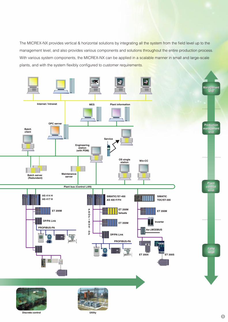
The MICREX-NX provides vertical & horizontal solutions by integrating all the system from the field level up to the
management level, and also provides various components and solutions throughout the entire production process.
With various system components, the MICREX-NX can be applied in a scalable manner in small and large-scale
plants, and with the system flexibly configured to customer requirements.
MICREX-PIIIMICREX-IX
PROFIBUS-PA
OCSDBSIOSIDS
DPCS-F
PCS-500
ICS-2500
ICS-2000
ACS-2000
SAS
MICREX-AX
OS WebClient
OS client(4 VGA)
OS client(2 VGA) OS client
Webserver
Terminal bus(Information LAN)
OS server(Migration) AOS
ADS
FL-net
OS server (Redundant)
Archive server Route control server (Redundant)
AS 417AS 416AS 414
P/PE-LINK
T-LINK
Optical FFI
EPAP
D-LINE
Intelligent MCC
Logistics Process control Discrete control Utility
PROFIBUSˡ
DP
PROFIBUSˡ
DP
ET 200M
AS 414 HAS 417 H
SIMATIC/S7-400AS 400 F/FH
SIMATICTDC/ST-300
ET 200M
ET 200X ET 200S
Inverter
As-i,MODBUS
ET 200M ET 200Mfailsafe
ET 200M
DP/PA Link
DP/PA Link
PROFIBUS-PA
Serial
As-i,MODBUS
ET 200X ET 200S
Internet / Intranet MES
OPC server
Plant information
Batchclient
Service
Engineeringstation
(with PDM)
Batch server (Redundant)
Maintenanceserver
Plant bus (Control LAN)
OS singlestation Win-CC
OS: Operator StationES: Engineering StationAS: Automation System
Managementlevel
Managementlevel
Productionmanagement
level
Productionmanagement
level
Plantcontrol
level
Plantcontrol
level
FieldlevelFieldlevel
Inverter
Inverter

H a r d w a r e
6
HardwareInnovative system based on open architecture and standard componentsBuilt-in advanced technologies and open communication environment realize high availability.
Fast standard network links robust high-performance controller and latest IT based operator
station to provide enhanced system reliability and added value for your plant.
The MICREX-NX features FUJI's expertise integrated with Simatic PCS7 by Siemens. The
hardware is compatible with the highly reliable PLC Simatic S7 series.
Control Station
Automation System (AS)
The controller equipped with high-performance CPU greatly
reduces costs throughout the entire lifecycle of your plant.
Depending on your system requirements, you can choose
from standard, redundant, and failsafe designs, and also
lineup varying scalability of the CPU. The controller module
can be changeable during runtime operation, enabling
flexible modification of the system.
Redundant controller
Remote PIO
The Remote PIO can be supplied in standard or failsafe use,
depending on your application. Since field devices can be
connected directly to the system, this minimizes the field
wiring cost.
Communication
Open Ethernet and standard PROFIBUS network technology
are used for MICREX-NX data communications.
The plant bus and the Terminal bus transfer the data
promptly at a rate of 100 Mbps via simultaneous and
duplex communications. With excellent built-in self-
diagnostics and redundant configuration, supremely
stable operations are assured. The network supports
up to 5 km by electric cable, and 150 km by fiber
optical cable connected to switching modules.
Ethernet
The field network is based on the globally used
PROFIBUS-DP/PA, so signals from field devices
can be carried quickly, safely, and on a scalable
basis. The advantages of PROFIBUS technology
are including distributed installation reduces space
requirements and cabling costs,
easy and efficient engineering, and
improves commissioning times.
PROFIBUS
DP/PA Link
Standard PIO
Failsafe PIO
ESM (Electrical Switching Module)
OSM (Optical Switching Module)
7
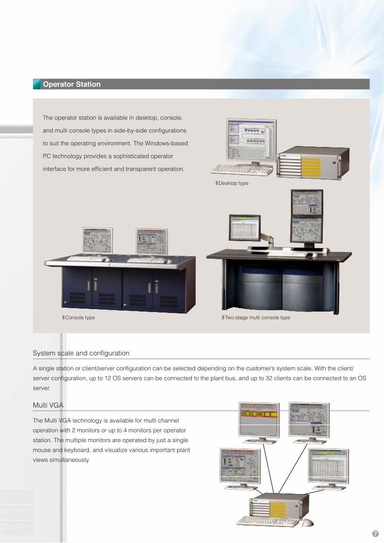
Operator Station
The operator station is available in desktop, console,
and multi console types in side-by-side configurations
to suit the operating environment. The Windows-based
PC technology provides a sophisticated operator
interface for more efficient and transparent operation.
System scale and configuration
A single station or client/server configuration can be selected depending on the customer’s system scale. With the client/
server configuration, up to 12 OS servers can be connected to the plant bus, and up to 32 clients can be connected to an OS
server.
Multi VGA
The Multi VGA technology is available for multi channel
operation with 2 monitors or up to 4 monitors per operator
station. The multiple monitors are operated by just a single
mouse and keyboard, and visualize various important plant
views simultaneously.
Desktop type
Console type Two-stage multi console type

H u m a ni n t e r f a c e
8
Human InterfaceAn excellent operational and functional operating environment ensures timely monitoring of your plant and accurate plant operations.
Standard user interface
Hierarchical architecture
The hierarchical architecture and the navigation windows based on the actual plant structure makes easily jump to a target plant screen.
Alarm Line:Displays the latest or most critical alarm at all times.
Overview Section:Directly calls up the plant screen in a hierarchical structure.
Working area:Displays the plant screen, and monitoring and operate the
plant.
Button area:Operation buttons for various functions.
Operation
Faceplate
Adjustment of PID parameters and operation of control signals can be done easily by visual faceplate window.
Standard interface
Compatible with general Windows applications, such as Excel, multimedia.
Report
With a wealth of data gathering and calculation functions, and possible simply creates the customized formats.
Logon screen
User administration by ID and password are available throughout the plant.
Operation log
The operation log can be displayed for easy browsing and sorting.

9
Alarm function
The loop-in alarm function navigates to the source of the failure
rapidly, and the system analyzes the overall alarms. Just click the
alarm on the screen can jump to the area where it is occurring. You
can search alarms, based on the date, time, area of occurrence, and
priority etc.
Functionality
Classification of alarm listsNew alarm, Acknowledged alarm, Outgoing alarm, System alarm,
Operator alarm, Alarm log etc.
Level of alarmColor-coded display of high level alarm, medium level alarm, and low
level alarm.
Priority of alarmUp to 16 classes of priority can be set.
Trend function
Flexibly displays requested trend, and quick response to the
online trend.
SFC visualization
The progress of a sequence can be displayed online,
so that process steps and transition conditions can be
controlled online. The sequence can be forcibly stopped,
and then restarted or canceled at the stopped position.
SFC overview
SFC chart
Process transition condition
SFC visualization
Features· Up to 10 color-coded trends can be displayed in each
trend field.· Ruler function and zoom function in tabular form data
display.· Search and log index by time.· Trend display/temporary display suspension functions.
Security function
Multiple-level security measures can be made by setting the access authority for each plant area/facilities/function (by user or group), electronic signature, and audit function with an IC card reader.

E n g i n e e r i n g
10
Central engineering I n t e g r a t e d E n g i n e e r i n g
EngineeringEfficiently develop a high-integrity system within an innovative and central engineering environment via a smooth engineering workflow.
The engineering toolset and copious libraries offer highly reliable supervisory operations
and flexible control functions. The know-how of the plant can be registered in the library as a
module, and the project parameters and documents can also be stored as engineering data.
And all these are useful when expanding or replacing your system.
In addition to standard hardware and software configurations, all application development tasks, such as asset management,
batch control and safety systems are engineered in a common engineering environment integrated by a uniform database.
The uniform database of the engineering station (ES) ensures that data, once entered, is accessible by all tools throughout
the project. This saves time taken for data re-entry for multiple usage and also prevents data entry errors. The hardware
configurations and application software can even be modified and downloaded online to the controller.
CFCFaceplatedesigner
Uniform database
Versioncross-checker
Bach systemSFC PDM
Import /Export assistant
Simulation Plant hierarchy
Safetysystem
Libraries
Hardwareconfiguration
Win CCgraphics designer
CFC C o n t i n u o u s F u n c t i o n C h a r t
CFC is the tool for continuous control functions. Pre-
engineered function blocks can be positioned by drag &
drop, and configured and interconnected graphically in the
CFC editor.* The block symbols and faceplates on the OS are created automatically.
SFC is a tool used to define control sequences and phases
by configuring step transitions and transit conditions. SFC is
also a standard tool which compliant with IEC61131-3.* The SFC visualization display that can allow observation of step transition
online on OS is automatically created without additional engineering.
SFC S e q u e n t i a l F u n c t i o n C h a r t

11
All the system components used, from field to HMI, are
configured in Hardware configuration. The required
hardware can be selected from an electronic catalog by
drag & drop, subsequently clicking the symbols to make
detailed settings.
Hardware configuration H a r d w a r e c o n f i g u r a t i o n
The Plant hierarchy is designed based on the actual layout
of the target plant, facilitating an overview of the functions of
the entire plant.* A hierarchical process graphic display with a navigation window is
automatically created on the OS.
Plant hierarchy P l a n t h i e r a r c h y
By copying the necessary elements from the library to
the basic frame and making a modification, a customized
faceplate can easily be created.
Faceplate designer F a c e p l a t e d e s i g n e r
Standard libraries, special libraries for each industry, and
the customized libraries that are created by your own plant
expertise significantly reduce engineering time and the
overall project cost.
Library L i b r a r y
By importing or exporting pre-
existing project data, such as
an Excel sheet, you can create
multiple corresponding programs,
using a single control logic
template, which can significantly
shorten the engineering time.
Import/Export assistant I m p o r t / E x p o r t a s s i s t a n t
Control software can be debugged on the engineering
station without connecting the actual systems with
a simulation tool.
Furthermore, an I/O
simulator and plant
simulator are available
for more sophisticated
simulations.
Simulation S i m u l a t i o n
The version cross-checker tool allows the user to quickly
determine the differences between two versions of CFCs/
SFCs, block types, and signals. The comparison results are
displayed in tree or tabular format with color-coding, and
can be printed out and archived in CSV format data.
Version cross-checker V e r s i o n c r o s s c h e c k e r
Plant
FacilitiesDevice
Control point
Faceplate designer Faceplate frame Faceplate
CAD/CAE
Standardlibrary
Tag chart
Hierarchical OS screens
Technical hierarchy
OS screen
Import/export assistant
T2659
��
��
Reactor
��
OS client
OS server
ET 200M
AS
Field device
PROFIBUS-DP
PROFIBUS-PA

S t a b i l i t yo p e r a t i o n
12
Redundant architecture
Long-term stable operationMICREX-NX offers a reduction in the Total Cost of Ownership (TCO) by high reliability at all levels of system and optimized migration strategy.
MICREX-NX offers flexible redundant configuration at all levels of the system.
The sturdy hardware design and strict security measures ensure totally reliable, safe plant
operations.
Furthermore, the migration with innovative technologies achieves long-term stable operation
and safeguards your investments.
MICREX-NX offers redundant configuration at all system levels, such as PIOs, controllers, operator stations, and the network.
This minimizes the risk of losses due to production downtime.
OS client, OS server
With client/server architecture, up to 32 clients can access
the data of a single OS server. The OS servers can be
redundant with hot standby technology, which will switch
transparently from the primary to the backup server in the
event of a system failure. The batch and archive servers can
also be redundant.
Communication
The Terminal bus and the Plant bus, based on Ethernet
technology, can be implemented using a redundant ring
architecture to further increase availability. A PROFIBUS
connected to remote PIOs can also be redundant.
Automation System (AS)
In a redundant AS architecture, the primary CPU
automatically switch to the backup CPU performs at less
than l00 ms (standard: 30 ms), and thus can be used for
systems where no production interruption is acceptable.
The redundant AS architecture can be performed via
modular bases, such as a CPU module, power supply
module, and a communications processor module.
Furthermore, the CPU module can be exchanged online,
and the data and programs can be automatically loaded
from the running CPU.
PIO
The remote PIO are open to redundancy in a per rack basis
(shelf) or per I/O modules. The I/O modules can also be
exchanged online.
OS client
OS server (Redundant)
AS 414 HAS 417 H
Sensor/actuator
DP/PA Link
PROFIBUS-PA
PROFIBUS-
DP
ET 200M
ET 200M
Batch server(Redundant)
Terminal bus (Redundant)
Plant bus (Redundant)
Route control server (Redundant)

13
Migration
MICREX-NX offers a migration strategy, which can modernize the existing system partially and in steps, and also protects
customer investment by continuously using the installed hardware and software.
HMI
Migration examples
Existing system STEP 1 STEP 2 Complete new system
Controller Controller Controller Controller
I/O I/O I/O I/O
HMI HMI HMI
OS gateway server
The MICREX-NX plant bus can connect to the DPCS-F or FL-net capable LAN of the existing system’s control network.
Via an OS gateway server, the OS client can access an existing controller and data transmission is possible between the AS
and the existing controllers.
Link device for T-link and D-line
MICREX-NX provides a link device for connecting to an existing remote I/O network T-link or D-line, allowing the use of
installed PIOs.
Link device for P/PE-link
MICREX-NX provides a link device for connecting to an existing P/PE-link, which can exchange data with a general-purpose
PLC connected in an existing system.
The message communication function and redundancy function of the P/PE-link can be re-integrated into the MICREX-NX
system.
The existing system with MICREX-PIII, MICREX-IX, and MICREX-AX can be migrated to MICREX-NX. The following migration
components are also available:
1) Connection with existing system
Succession of functions of the existing application programs (ladder diagram, FB diagram, SFC, loop diagram, etc.) can be
used as control programs of the MICREX-NX via the software conversion function. The engineering information held by the
existing system can also be imported into the MICREX-NX engineering environment.
2) Succession of existing systems's function

S o l u t i o np a c k a g e
14
Solution Packages
Batch system B a t c h s y s t e m
The Batch system is the system for limited production of a wide variety of products. The system compliance with IEC61512
(ISA S88), and provides various functions, such as recipe creation, lot/batch monitoring, plant/unit monitoring, batch
production control, batch data management, and batch reports etc.
Plant RecipeProcedure Master
Dosing master
Transfer
Reactor
Preparationof reactor
Acceptance
Mixer
Transfer
Start
Preparation Temperatureincrease Pressurization
Cooling
Complete
Separator
Separationpreparingmachine
To separator
Recipe UnitProcedure
RecipeOperation
RecipeFunction
Unit
TechnicalEquipment
ControlUnit
Batch reportBatch planning Batch controlRecipe editor Batch control Batch reportRecipe editor Batch planning
Function
• Library for recipe definition (ROP)
• Recipe system independent of the running unit
• Batch management independently of type
parameters and procedure definition
• XML-based archive and report system
• Compliance with FDA 21 CFR Part 11
The MICREX-NX can securely manage production record
data, such as process data, electronic signature, and audit
trails, so fully conforms to FDA 21 CFR Part 11.
* FDA: The U.S. Food and Drug Administration
* 21 CFR Part 11: Regulations governing user management, electronic signature, and audit trail stipulated by FDA
Compliance with FDA 21 CFR Part 11 21 CFR Part 11
Using the Web server function can perform supervisory
control via Internet/Intranet. Web clients can access to
the Web server simply by setting Internet Explorer (IE)
appropriately.
OS Web client O S W e b c l i e n t
The Route Control system, which efficiently performs the
monitoring, control, and diagnostics of automatic material
transports in pipeline networks, can be used for plants with
a multitude of complex route combinations or tank farms,
such as food and drinks, pharmaceutical, chemical, and
petrochemical industries.
Route Control system R o u t e C o n t r o l s y s t e m
The Archive server can be used for the long-term storage
of data held by all the OS and batch servers (process
values, alarms, and batch data). The archived data can be
visualized on the OS clients and swapped out to all external
storage media (e.g. DVD).
Archive server A r c h i v e s e r v e r
MICREX-NX solution packages realize sophisticated information integration and communication in a control system, and correspond to security issues, industry standards, and various laws and regulations.
The application packages can be engineered in a common engineering environment, and
provide optimized solutions.
15
Standard program
Safety program
Standard program
Safety program
Standard program
Failsafe I/O DP slave
TCP/IP
S
Safety communication data Controldata
Counterdata CRC
Source basecount
Safety dataparameter
Standardcommunication data
Max.12bzw.122Bytes 1Byte 1Byte 2/4Bytes*) 240/238F-Nutz
S S S S S
Firewall Safety sensorDP slave
Standard I/ODP slave
Gateway to other safety networks
Emergency shutdown button
AS 417F
PROFIBUS-DP
Standard communication and safety data communication achieved with only one bus
Communication telegram
Max.244 bytesPROFIBUS-DP communication data
PROFIBUS-DPStandard communication telegram
OS
Engineering stationwith PDM
Stand-alone stationwith PDM
SIMOCODE
ET 200M
0/4—20 mA + HART
DP/PA Link
Electronic Device Description Language (EDDL)
Process value/status
Customized parameter
Standardized parameter(self diagnostics)
ES
ASPROFIBUS-DP
Ethernet
PROFIBUS-PA
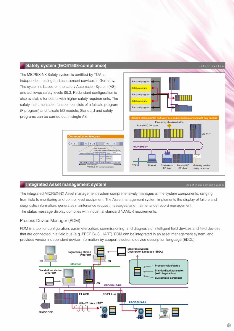
Safety system (IEC61508-compliance) S a f e t y s y s t e m
The MICREX-NX Safety system is certified by TÜV, an
independent testing and assessment services in Germany.
The system is based on the safety Automation System (AS),
and achieves safety levels SIL3. Redundant configuration is
also available for plants with higher safety requirements. The
safety instrumentation function consists of a failsafe program
(F program) and failsafe I/O module. Standard and safety
programs can be carried out in single AS.
Integrated Asset management system A s s e t m a n a g e m e n t s y s t e m
The integrated MICREX-NX Asset management system comprehensively manages all the system components, ranging
from field to monitoring and control level equipment. The Asset management system implements the display of failure and
diagnostic information, generates maintenance request messages, and maintenance record management.
The status message display complies with industrial standard NAMUR requirements.
Process Device Manager (PDM)
PDM is a tool for configuration, parameterization, commissioning, and diagnosis of intelligent field devices and field devices
that are connected in a field bus (e.g. PROFIBUS, HART). PDM can be integrated in an asset management system, and
provides vendor independent device information by support electronic device description language (EDDL).

2006-7(G06/G06) 10FIS Printed in Japan
Lifecycle solution for inheritance of your assets and minimizing your investment.
Maintenance service systemCall Center
Our call center quickly responds to failure notification from our
customers 24 hours a day, every day. The call center also provides
technical consultation and remote maintenance services for all of
our delivered products.
Our service staff will be promptly dispatched on-site from our
maintenance bases located nationwide.
Customer
Call Center
Sales
Logistics Repaircenter Support
CE(CustomerEngineer)
������������������������������������������
�������������������������
Inquiry �����������������������������
Ethernet is a registered trademark of Xerox Corp. in the U.S.A.Windows, Excel, and Explorer are registered trademarks of Microsoft Corp. in the U.S.A.PROFIBUS is a registered trademark of PROFIBUS Organization.OPC is a registered trademark of OPC Foundation.SIMATIC is a registered trademark of Siemens AG in Germany.Other products and company names listed in this catalog are trademarks or registered trademarks of each company.
ContactFUJI ELECTRIC SYSTEMS Co., Ltd.e-Solution Group, Process and Information Automation Div.
TEL.042-585-6165 FAX.042-587-8806