Embed Size (px)
Citation preview

ECE/CS 250 Computer Architecture
Summer 2018
I/O
Tyler Bletsch
Duke University
Includes material adapted from Dan Sorin (Duke) and Amir Roth (Penn).
SSD material from Andrew Bondi (Colorado State).
2
Where We Are in This Course Right Now
• So far:
• We know how to design a processor that can fetch, decode, and execute the instructions in an ISA
• We understand how to design caches and memory
• Now:
• We learn about the lowest level of storage (disks)
• We learn about input/output in general
• Next:
• Faster processor cores
• Multicore processors
3
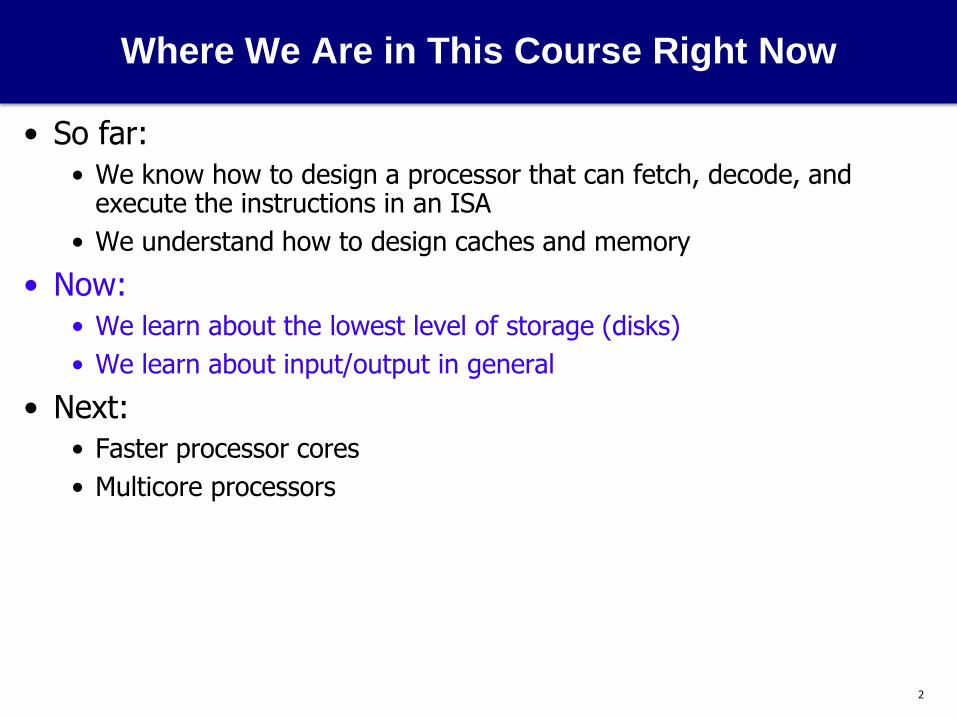
This Unit: I/O
• I/O system structure
• Devices, controllers, and buses
• Device characteristics
• Disks
• Bus characteristics
• I/O control
• Polling and interrupts
• DMA
Application
OS
Firmware Compiler
I/O
Memory
Digital Circuits
Gates & Transistors
CPU
4
Readings
• Patterson and Hennessy dropped the ball on this topic
• It used to be covered in depth (in previous editions)
• Now it’s sort of in Appendix A.8

5
Computers Interact with Outside World
• Input/output (I/O)
• Otherwise, how will we ever tell a computer what to do…
• …or exploit the results of its work?
• Computers without I/O are not useful
• ICQ: What kinds of I/O do computers have?

6
One Instance of I/O
• Have briefly seen one instance of I/O
• Disk: bottom of memory hierarchy
• Holds whatever can’t fit in memory
• ICQ: What else do disks hold?
CPU
D$
L2
Main
Memory
I$
Disk(swap)
7
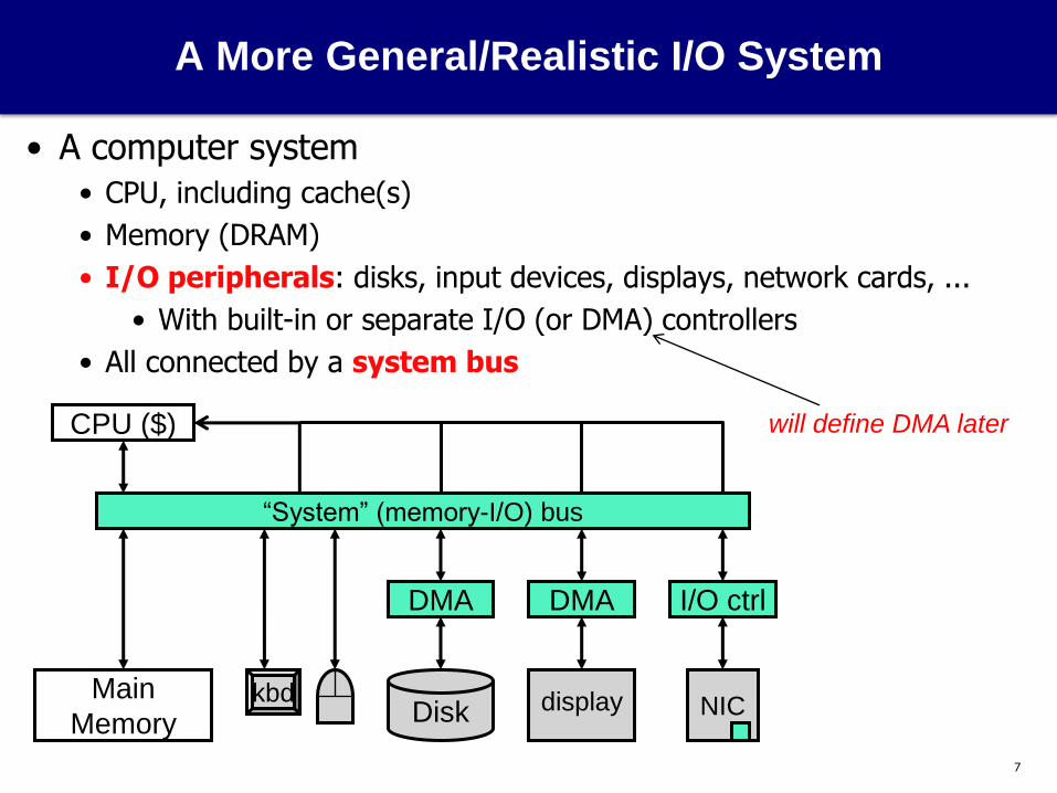
A More General/Realistic I/O System
• A computer system
• CPU, including cache(s)
• Memory (DRAM)
• I/O peripherals: disks, input devices, displays, network cards, ...
• With built-in or separate I/O (or DMA) controllers
• All connected by a system bus
CPU ($)
Main
Memory Disk kbd
DMA DMA
display NIC
I/O ctrl
“System” (memory-I/O) bus
will define DMA later

8
I/O: Control + Data Transfer
• I/O devices have two ports
• Control: commands and status reports
• How we tell I/O what to do
• How I/O tells us about itself
• Control is the tricky part (especially status reports)
• Data
• Labor-intensive part
• “Interesting” I/O devices do data transfers (to/from memory)
• Display: video memory monitor
• Disk: memory disk
• Network interface: memory network
9
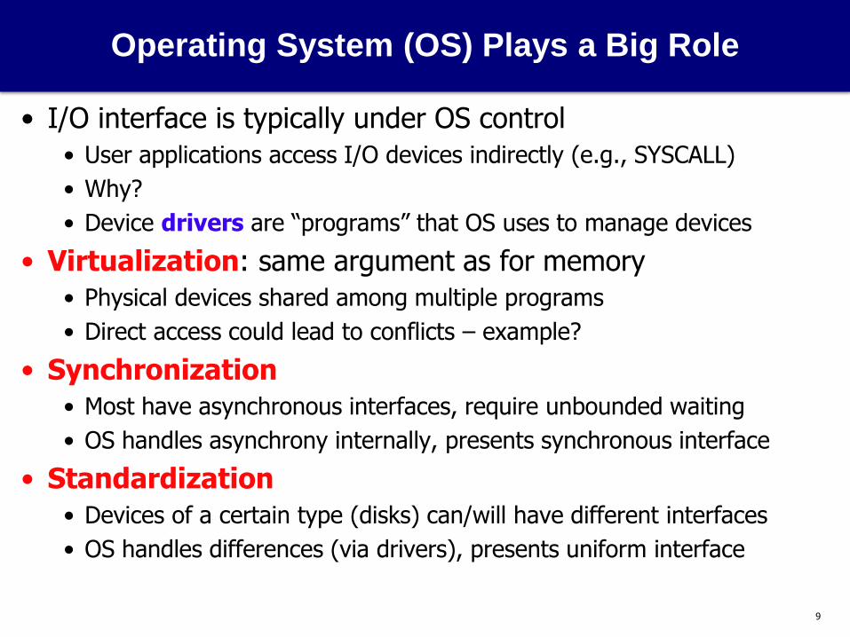
Operating System (OS) Plays a Big Role
• I/O interface is typically under OS control
• User applications access I/O devices indirectly (e.g., SYSCALL)
• Why?
• Device drivers are “programs” that OS uses to manage devices
• Virtualization: same argument as for memory
• Physical devices shared among multiple programs
• Direct access could lead to conflicts – example?
• Synchronization
• Most have asynchronous interfaces, require unbounded waiting
• OS handles asynchrony internally, presents synchronous interface
• Standardization
• Devices of a certain type (disks) can/will have different interfaces
• OS handles differences (via drivers), presents uniform interface

10
I/O Device Characteristics
• Primary characteristic
• Data rate (aka bandwidth)
• Contributing factors
• Partner: humans have slower output data rates than machines
• Input or output or both (input/output)
Device Partner I? O? Data Rate (KB/s)
Keyboard Human Input 0.01
Mouse Human Input 0.02
Speaker Human Output 0.60
Printer Human Output 200
Display Human Output 240,000
Modem (old) Machine I/O 7
Ethernet Machine I/O ~1,000,000
Disk Machine I/O ~50,000
11
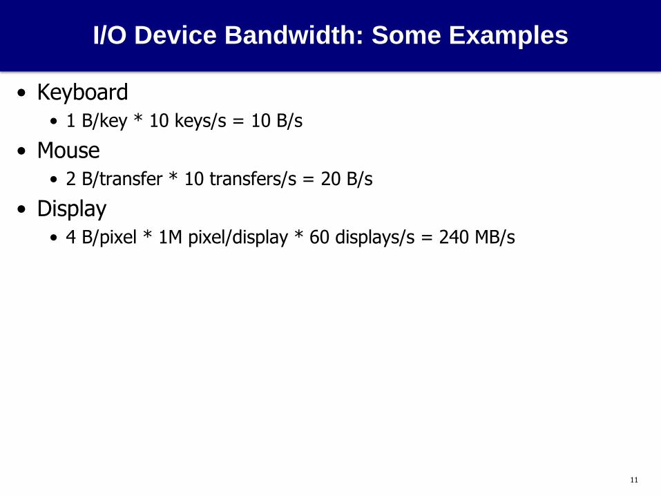
I/O Device Bandwidth: Some Examples
• Keyboard
• 1 B/key * 10 keys/s = 10 B/s
• Mouse
• 2 B/transfer * 10 transfers/s = 20 B/s
• Display
• 4 B/pixel * 1M pixel/display * 60 displays/s = 240 MB/s
12
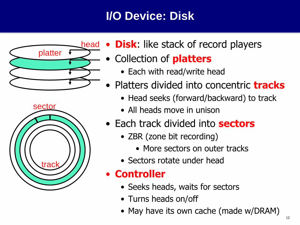
I/O Device: Disk
• Disk: like stack of record players
• Collection of platters
• Each with read/write head
• Platters divided into concentric tracks
• Head seeks (forward/backward) to track
• All heads move in unison
• Each track divided into sectors
• ZBR (zone bit recording)
• More sectors on outer tracks
• Sectors rotate under head
• Controller
• Seeks heads, waits for sectors
• Turns heads on/off
• May have its own cache (made w/DRAM)
platter head
sector
track

13
Disk Parameters
Seagate 6TB Enterprise HDD (2016)
Seagate Savvio (~2005)
Toshiba MK1003 (early 2000s)
Diameter 3.5” 2.5” 1.8”
Capacity 6 TB 73 GB 10 GB
RPM 7200 RPM 10000 RPM 4200 RPM
Cache 128 MB 8 MB 512 KB
Platters ~6 2 1
Average Seek 4.16 ms 4.5 ms 7 ms
Sustained Data Rate 216 MB/s 94 MB/s 16 MB/s
Interface SAS/SATA SCSI ATA
Use Desktop Laptop Ancient iPod

14
Disk Read/Write Latency
• Disk read/write latency has four components
• Seek delay (tseek): head seeks to right track
• Rotational delay (trotation): right sector rotates under head
• On average: time to go halfway around disk
• Transfer time (ttransfer): data actually being transferred
• Controller delay (tcontroller): controller overhead (on either side)
• Example: time to read a 4KB page assuming…
• 128 sectors/track, 512 B/sector, 6000 RPM, 10 ms tseek, 1 ms tcontroller
• 6000 RPM 100 R/s 10 ms/R trotation = 10 ms / 2 = 5 ms
• 4 KB page 8 sectors ttransfer = 10 ms * 8/128 = 0.6 ms
• tdisk = tseek + trotation + ttransfer + tcontroller
= 10 + 5 + 0.6 + 1 = 16.6 ms

15
Understanding disk performance
• One 🕐 equals 1 microsecond
• Time to read the “next” 512-byte sector (no seek needed): 🕐 🕐 ~2μs
• Time to read a random 512-byte sector (with seek): 🕐🕐🕐🕐🕐🕐🕐🕐🕐🕐🕐🕐🕐🕐🕐🕐🕐🕐🕐🕐🕐🕐🕐🕐🕐🕐🕐🕐🕐🕐🕐🕐🕐🕐🕐🕐🕐🕐🕐🕐🕐🕐🕐🕐🕐🕐🕐🕐🕐🕐🕐🕐🕐🕐🕐🕐🕐🕐🕐🕐🕐🕐🕐🕐🕐🕐🕐🕐🕐🕐🕐🕐🕐🕐🕐🕐🕐🕐🕐🕐🕐🕐🕐🕐🕐🕐🕐🕐🕐🕐🕐🕐🕐🕐🕐🕐🕐🕐🕐🕐🕐🕐🕐🕐🕐🕐🕐🕐🕐🕐🕐🕐🕐🕐🕐🕐🕐🕐🕐🕐🕐🕐🕐🕐🕐🕐🕐🕐🕐🕐🕐🕐🕐🕐🕐🕐🕐🕐🕐🕐🕐🕐🕐🕐🕐🕐🕐🕐🕐🕐🕐🕐🕐🕐🕐🕐🕐🕐🕐🕐🕐🕐🕐🕐🕐🕐🕐🕐🕐🕐🕐🕐🕐🕐🕐🕐🕐🕐🕐🕐🕐🕐🕐🕐🕐🕐🕐🕐🕐🕐🕐🕐🕐🕐🕐🕐🕐🕐🕐🕐🕐🕐🕐🕐🕐🕐🕐🕐🕐🕐🕐🕐🕐🕐🕐🕐🕐🕐🕐🕐🕐🕐🕐🕐🕐🕐🕐🕐🕐🕐🕐🕐🕐🕐🕐🕐🕐🕐🕐🕐🕐🕐🕐🕐🕐🕐🕐🕐🕐🕐🕐🕐🕐🕐🕐🕐🕐🕐🕐🕐🕐🕐🕐🕐🕐🕐🕐🕐🕐🕐🕐🕐🕐🕐🕐🕐🕐🕐🕐🕐🕐🕐🕐🕐🕐🕐🕐🕐🕐🕐🕐🕐🕐🕐🕐🕐🕐🕐🕐🕐🕐🕐🕐🕐🕐🕐🕐🕐🕐🕐🕐🕐🕐🕐🕐🕐🕐🕐🕐🕐🕐🕐🕐🕐🕐🕐🕐🕐🕐🕐🕐🕐🕐🕐🕐🕐🕐🕐🕐🕐🕐🕐🕐🕐🕐🕐🕐🕐🕐🕐🕐🕐🕐🕐🕐🕐🕐🕐🕐🕐🕐🕐🕐🕐🕐🕐🕐🕐🕐🕐🕐🕐🕐🕐🕐🕐🕐🕐🕐🕐🕐🕐🕐🕐🕐🕐🕐🕐🕐🕐🕐🕐🕐🕐🕐🕐🕐🕐🕐🕐🕐🕐🕐🕐🕐🕐🕐🕐🕐🕐🕐🕐🕐🕐🕐🕐🕐🕐🕐🕐🕐🕐🕐🕐🕐🕐🕐🕐🕐🕐🕐🕐🕐🕐🕐🕐🕐🕐🕐🕐🕐🕐🕐🕐🕐🕐🕐🕐🕐🕐🕐🕐🕐🕐🕐🕐🕐🕐🕐🕐🕐🕐🕐🕐🕐🕐🕐🕐🕐🕐🕐🕐🕐🕐🕐🕐🕐🕐🕐🕐🕐🕐🕐🕐🕐🕐🕐🕐🕐🕐🕐🕐🕐🕐🕐🕐🕐🕐🕐🕐🕐🕐🕐🕐🕐🕐🕐🕐🕐🕐🕐🕐🕐🕐🕐🕐🕐🕐🕐🕐🕐🕐🕐🕐🕐🕐🕐🕐🕐🕐🕐🕐🕐🕐🕐🕐🕐🕐🕐🕐🕐🕐🕐🕐🕐🕐🕐🕐🕐🕐🕐🕐🕐🕐🕐🕐🕐🕐🕐🕐🕐🕐🕐🕐🕐🕐🕐🕐🕐🕐🕐🕐🕐🕐🕐🕐🕐🕐🕐🕐🕐🕐🕐🕐🕐🕐🕐🕐🕐🕐🕐🕐🕐🕐🕐🕐🕐🕐🕐🕐🕐🕐🕐🕐🕐🕐🕐🕐🕐🕐🕐🕐🕐🕐🕐🕐🕐🕐🕐🕐🕐🕐🕐🕐🕐🕐🕐🕐🕐🕐🕐🕐🕐🕐🕐🕐🕐🕐🕐🕐🕐🕐🕐🕐🕐🕐🕐🕐🕐🕐🕐🕐🕐🕐🕐🕐🕐🕐🕐🕐🕐🕐🕐🕐🕐🕐🕐🕐🕐🕐🕐🕐🕐🕐🕐🕐🕐🕐🕐🕐🕐🕐🕐🕐🕐🕐🕐🕐🕐🕐🕐🕐🕐🕐🕐🕐🕐🕐🕐🕐🕐🕐🕐🕐🕐🕐🕐🕐🕐🕐🕐🕐🕐🕐🕐🕐🕐🕐🕐🕐🕐🕐🕐🕐🕐🕐🕐🕐🕐🕐🕐🕐🕐🕐🕐🕐🕐🕐🕐🕐🕐🕐🕐🕐🕐🕐🕐🕐🕐🕐🕐🕐🕐🕐🕐🕐🕐🕐🕐🕐🕐🕐🕐🕐🕐🕐🕐🕐🕐🕐🕐🕐🕐🕐🕐🕐🕐🕐🕐🕐🕐🕐🕐🕐🕐🕐🕐🕐🕐🕐🕐🕐🕐🕐🕐🕐🕐🕐🕐🕐🕐🕐🕐🕐🕐🕐🕐🕐🕐🕐🕐🕐🕐🕐🕐🕐🕐🕐🕐🕐🕐🕐🕐🕐🕐🕐🕐🕐🕐🕐🕐🕐🕐🕐🕐🕐🕐🕐🕐🕐🕐🕐🕐🕐🕐🕐🕐🕐🕐🕐🕐🕐🕐🕐🕐🕐🕐🕐🕐🕐🕐🕐🕐🕐🕐🕐🕐🕐🕐🕐🕐🕐🕐🕐🕐🕐🕐🕐🕐🕐🕐🕐🕐🕐🕐🕐🕐🕐🕐🕐🕐🕐🕐🕐🕐🕐🕐🕐🕐🕐🕐🕐🕐🕐🕐🕐🕐🕐🕐🕐🕐🕐🕐🕐🕐🕐🕐🕐🕐🕐🕐🕐🕐🕐🕐🕐🕐🕐🕐🕐🕐🕐🕐🕐🕐🕐🕐🕐🕐🕐🕐🕐🕐🕐🕐🕐🕐🕐🕐🕐🕐🕐🕐🕐🕐🕐🕐🕐🕐🕐🕐🕐🕐🕐🕐🕐🕐🕐🕐🕐🕐🕐🕐🕐🕐🕐🕐🕐🕐🕐🕐🕐🕐🕐🕐🕐🕐🕐🕐🕐🕐🕐🕐🕐🕐🕐🕐🕐🕐🕐🕐🕐🕐🕐🕐🕐🕐🕐🕐🕐🕐🕐🕐🕐🕐🕐🕐🕐🕐🕐🕐🕐🕐🕐🕐🕐🕐🕐🕐🕐🕐🕐🕐🕐🕐🕐🕐🕐🕐🕐🕐🕐🕐🕐🕐🕐🕐🕐🕐🕐🕐🕐🕐🕐🕐🕐🕐🕐🕐🕐🕐🕐🕐🕐🕐🕐🕐🕐🕐🕐🕐🕐🕐🕐🕐🕐🕐🕐🕐🕐🕐🕐🕐🕐🕐🕐🕐🕐🕐🕐🕐🕐🕐🕐🕐🕐🕐🕐🕐🕐🕐🕐🕐🕐🕐🕐🕐🕐🕐🕐🕐🕐🕐🕐🕐🕐🕐🕐🕐🕐🕐🕐🕐🕐🕐🕐🕐🕐🕐🕐🕐🕐🕐🕐🕐🕐🕐🕐🕐🕐🕐🕐🕐🕐🕐🕐🕐🕐🕐🕐🕐🕐🕐🕐🕐🕐🕐🕐🕐🕐🕐🕐🕐🕐🕐🕐🕐🕐🕐🕐🕐🕐🕐🕐🕐🕐🕐🕐🕐🕐🕐🕐🕐🕐🕐🕐🕐🕐🕐🕐🕐🕐🕐🕐🕐🕐🕐🕐🕐🕐🕐🕐🕐🕐🕐🕐🕐🕐🕐🕐🕐🕐🕐🕐🕐🕐🕐🕐🕐🕐🕐🕐🕐🕐🕐🕐🕐🕐🕐🕐🕐🕐🕐🕐🕐🕐🕐🕐🕐🕐🕐🕐🕐🕐🕐🕐🕐🕐🕐🕐🕐🕐🕐🕐🕐🕐🕐🕐🕐🕐🕐🕐🕐🕐🕐🕐🕐🕐🕐🕐🕐🕐🕐🕐🕐🕐🕐🕐🕐🕐🕐🕐🕐🕐🕐🕐🕐🕐🕐🕐🕐🕐🕐🕐🕐🕐🕐🕐🕐🕐🕐🕐🕐🕐🕐🕐🕐🕐🕐🕐🕐🕐🕐🕐🕐🕐🕐🕐🕐🕐🕐🕐🕐🕐🕐🕐🕐🕐🕐🕐🕐🕐🕐🕐🕐🕐🕐🕐🕐🕐🕐🕐🕐🕐🕐🕐🕐🕐🕐🕐🕐🕐🕐🕐🕐🕐🕐🕐🕐🕐🕐🕐🕐🕐🕐🕐🕐🕐🕐🕐🕐🕐🕐🕐🕐🕐🕐🕐🕐🕐🕐🕐🕐🕐🕐🕐🕐🕐🕐🕐🕐🕐🕐🕐🕐🕐🕐🕐🕐🕐🕐🕐🕐🕐🕐🕐🕐🕐🕐🕐🕐🕐🕐🕐🕐🕐🕐🕐🕐🕐🕐🕐🕐🕐🕐🕐🕐🕐🕐🕐🕐🕐🕐🕐🕐🕐🕐🕐🕐🕐🕐🕐🕐🕐🕐🕐🕐🕐🕐🕐🕐🕐🕐🕐🕐🕐🕐🕐🕐🕐🕐🕐🕐🕐🕐🕐🕐🕐🕐🕐🕐🕐🕐🕐🕐🕐🕐🕐🕐🕐🕐🕐🕐🕐🕐🕐🕐🕐🕐🕐🕐🕐🕐🕐🕐🕐🕐🕐🕐🕐🕐🕐🕐🕐🕐🕐🕐🕐🕐🕐🕐🕐🕐🕐🕐🕐🕐🕐🕐🕐🕐🕐🕐🕐🕐🕐🕐🕐🕐🕐🕐🕐🕐🕐🕐🕐🕐🕐🕐🕐🕐🕐🕐🕐🕐🕐🕐🕐🕐🕐🕐🕐🕐🕐🕐🕐🕐🕐🕐🕐🕐🕐🕐🕐🕐🕐🕐🕐🕐🕐🕐🕐🕐🕐🕐🕐🕐🕐🕐🕐🕐🕐🕐🕐🕐🕐🕐🕐🕐🕐🕐🕐🕐🕐🕐🕐🕐🕐🕐🕐🕐🕐🕐🕐🕐🕐🕐🕐🕐🕐🕐🕐🕐🕐🕐🕐🕐🕐🕐🕐🕐🕐🕐🕐🕐🕐🕐🕐🕐🕐🕐🕐🕐🕐🕐🕐🕐🕐🕐🕐🕐🕐🕐🕐🕐🕐🕐🕐🕐🕐🕐🕐🕐🕐🕐🕐🕐🕐🕐🕐🕐🕐🕐🕐🕐🕐🕐🕐🕐🕐🕐🕐🕐🕐🕐🕐🕐🕐🕐🕐🕐🕐🕐🕐🕐🕐🕐🕐🕐🕐🕐🕐🕐🕐🕐🕐🕐🕐🕐🕐🕐🕐🕐🕐🕐🕐🕐🕐🕐🕐🕐🕐🕐🕐🕐🕐🕐🕐🕐🕐🕐🕐🕐🕐🕐🕐🕐🕐🕐🕐🕐🕐🕐🕐🕐🕐🕐🕐🕐🕐🕐🕐🕐🕐🕐🕐🕐🕐🕐🕐🕐🕐🕐🕐🕐🕐🕐🕐🕐🕐🕐🕐🕐🕐🕐🕐🕐🕐🕐🕐🕐🕐🕐🕐🕐🕐🕐🕐🕐🕐🕐🕐
🕐🕐🕐🕐🕐🕐🕐🕐🕐🕐🕐🕐🕐🕐🕐🕐🕐🕐🕐🕐🕐🕐🕐🕐🕐🕐🕐🕐🕐🕐🕐🕐🕐🕐🕐🕐🕐🕐🕐🕐🕐🕐🕐🕐🕐🕐🕐🕐🕐🕐🕐🕐🕐🕐🕐🕐🕐🕐 ~1840μs

16
Disk Bandwidth
• Disk is bandwidth-inefficient for page-sized transfers
• Actual data transfer (ttransfer) a small part of disk access (and cycle)
• Increase bandwidth: stripe data across multiple disks
• Striping strategy depends on disk usage model
• “File System” or “web server”: many small files
• Map entire files to disks
• “Supercomputer” or “database”: several large files
• Stripe single file across multiple disks
• Both bandwidth and individual transaction latency important

17
Error Correction: RAID
• Error correction: more important for disk than for memory
• Mechanical disk failures (entire disk lost) is common failure mode
• Entire file system can be lost if files striped across multiple disks
• RAID (redundant array of inexpensive disks)
• Similar to DRAM error correction, but…
• Major difference: which disk failed is known
• Even parity can be used to recover from single failures
• Parity disk can be used to reconstruct data faulty disk
• RAID design balances bandwidth and fault-tolerance
• Many flavors of RAID exist
• Tradeoff: extra disks (cost) vs. performance vs. reliability
• Deeper discussion of RAID in ECE 552 and ECE 554; super-duper deep coverage in ECE 566/590 (“Enterprise Storage Architecture”)
• RAID doesn’t solve all problems can you think of any examples?

18
What about Solid State Drives (SSDs)?
Adapted from “Solid State Drives” by Andrew Bondi
SSD HDD

19
SSDs
• Multiple NAND flash chips operated in parallel
• Pros:
• Extremely good “seek” times (since “seek” is no longer a thing)
• Almost instantaneous read and write times
• The ability to read or write in multiple locations at once
• The speed of the drive scales extremely well with the number of NAND ICs on board
• Way cheaper than disk per IOP (performance)
• Cons:
• Way more expensive than disk per GB (capacity)
• Limited number of write cycles possible before it degrades (getting less and less of a problem these days)
• Fundamental problem: Write amplification
• You can set bits in “pages” (~4kB) fast (microseconds), but you can only clear bits in “blocks” (~512kB) slooow (milliseconds)
• Solution: controller that is managing NAND cells tries to hide this
Adapted from “Solid State Drives” by Andrew Bondi
20
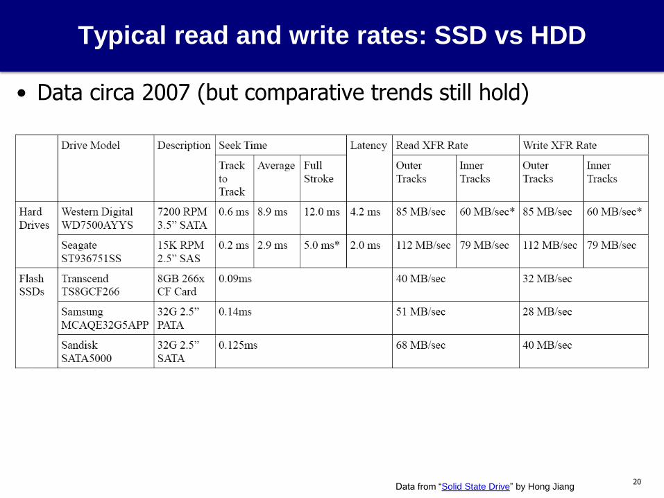
Typical read and write rates: SSD vs HDD
• Data circa 2007 (but comparative trends still hold)
Data from “Solid State Drive” by Hong Jiang

21
The System Bus
• System bus: connects system components together
• Important: insufficient bandwidth can bottleneck entire system
• Performance factors
• Physical length
• Number and type of connected devices (taps)
CPU ($)
Main
Memory Disk kbd
DMA DMA
display NIC
I/O ctrl
“System” (memory-I/O) bus
22
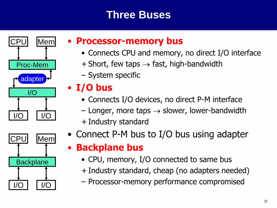
Three Buses
• Processor-memory bus
• Connects CPU and memory, no direct I/O interface
+ Short, few taps fast, high-bandwidth
– System specific
• I/O bus
• Connects I/O devices, no direct P-M interface
– Longer, more taps slower, lower-bandwidth
+ Industry standard
• Connect P-M bus to I/O bus using adapter
• Backplane bus
• CPU, memory, I/O connected to same bus
+ Industry standard, cheap (no adapters needed)
– Processor-memory performance compromised
CPU
I/O I/O
I/O
Mem
Proc-Mem
adapter
I/O I/O
Backplane
CPU Mem

23
Bus Design
• Goals
• High Performance: low latency and high bandwidth
• Standardization: flexibility in dealing with many devices
• Low Cost
• Processor-memory bus emphasizes performance, then cost
• I/O & backplane emphasize standardization, then performance
• Design issues
1. Width/multiplexing: are wires shared or separate?
2. Clocking: is bus clocked or not?
3. Switching: how/when is bus control acquired and released?
4. Arbitration: how do we decide who gets the bus next?
data lines
address lines
control lines
24
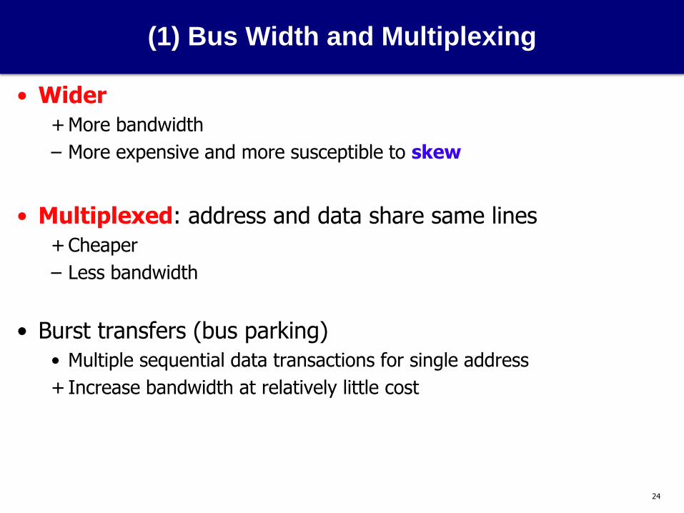
(1) Bus Width and Multiplexing
• Wider
+ More bandwidth
– More expensive and more susceptible to skew
• Multiplexed: address and data share same lines
+ Cheaper
– Less bandwidth
• Burst transfers (bus parking)
• Multiple sequential data transactions for single address
+ Increase bandwidth at relatively little cost

25
(2) Bus Clocking
• Synchronous: clocked
+ Fast
– Bus must be short to minimize clock skew
• Asynchronous: un-clocked
+ Can be longer: no clock skew, deals with devices of different speeds
– Slower: requires “hand-shaking” protocol
• For example, asynchronous read
• Multiplexed data/address lines, 3 control lines
1. Processor drives address onto bus, asserts Request line
2. Memory asserts Ack line, processor stops driving
3. Memory drives data on bus, asserts DataReady line
4. Processor asserts Ack line, memory stops driving
• Processor-Memory buses are synchronous
• I/O and backplane buses asynchronous or slow-clock synchronous
26
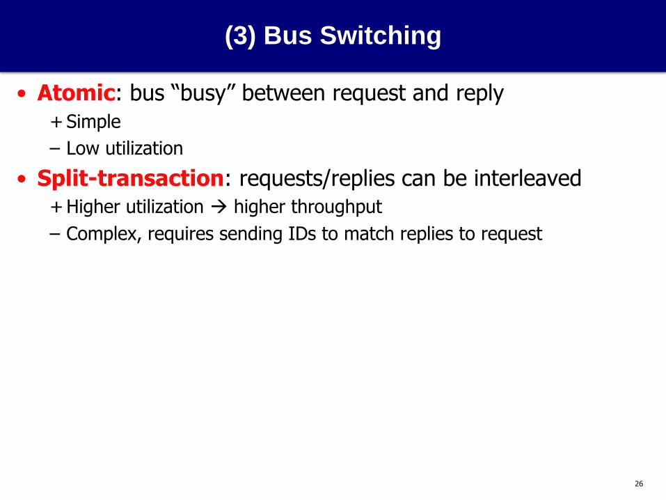
(3) Bus Switching
• Atomic: bus “busy” between request and reply
+ Simple
– Low utilization
• Split-transaction: requests/replies can be interleaved
+ Higher utilization higher throughput
– Complex, requires sending IDs to match replies to request
27
(4) Bus Arbitration
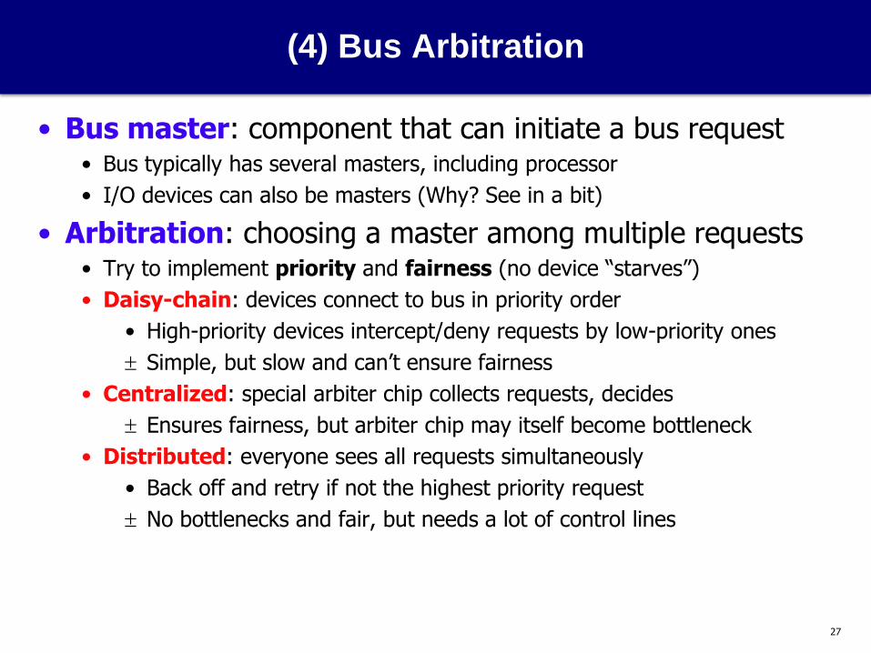
• Bus master: component that can initiate a bus request • Bus typically has several masters, including processor
• I/O devices can also be masters (Why? See in a bit)
• Arbitration: choosing a master among multiple requests • Try to implement priority and fairness (no device “starves”)
• Daisy-chain: devices connect to bus in priority order
• High-priority devices intercept/deny requests by low-priority ones
Simple, but slow and can’t ensure fairness
• Centralized: special arbiter chip collects requests, decides
Ensures fairness, but arbiter chip may itself become bottleneck
• Distributed: everyone sees all requests simultaneously
• Back off and retry if not the highest priority request
No bottlenecks and fair, but needs a lot of control lines
28
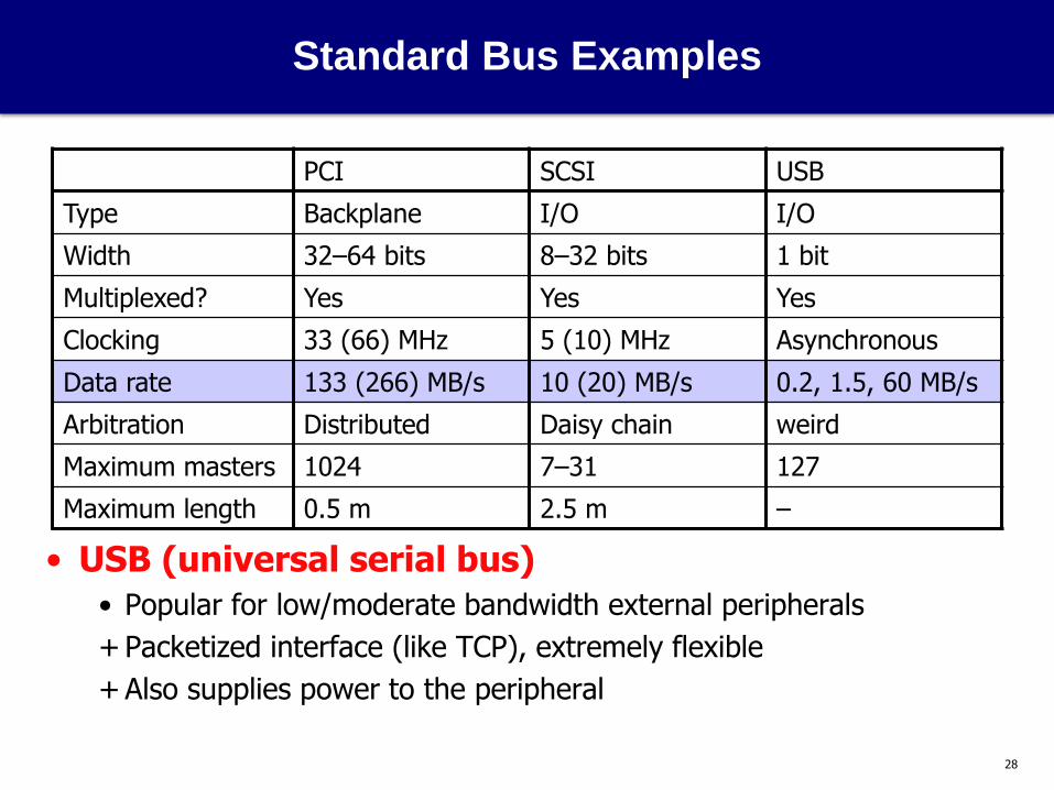
Standard Bus Examples
• USB (universal serial bus)
• Popular for low/moderate bandwidth external peripherals
+ Packetized interface (like TCP), extremely flexible
+ Also supplies power to the peripheral
PCI SCSI USB
Type Backplane I/O I/O
Width 32–64 bits 8–32 bits 1 bit
Multiplexed? Yes Yes Yes
Clocking 33 (66) MHz 5 (10) MHz Asynchronous
Data rate 133 (266) MB/s 10 (20) MB/s 0.2, 1.5, 60 MB/s
Arbitration Distributed Daisy chain weird
Maximum masters 1024 7–31 127
Maximum length 0.5 m 2.5 m –

29
This Unit: I/O
• I/O system structure
• Devices, controllers, and buses
• Device characteristics
• Disks
• Bus characteristics
• I/O control
• Polling and interrupts
• DMA
Application
OS
Firmware Compiler
I/O
Memory
Digital Circuits
Gates & Transistors
CPU
30
I/O Control and Interfaces
• Now that we know how I/O devices and buses work…
• How does I/O actually happen?
• How does CPU give commands to I/O devices?
• How do I/O devices execute data transfers?
• How does CPU know when I/O devices are done?

31
Sending Commands to I/O Devices
• Remember: only OS can do this! Two options …
• I/O instructions
• OS only? Instructions must be privileged (only OS can execute)
• E.g., IA-32
• Memory-mapped I/O
• Portion of physical address space reserved for I/O
• OS maps physical addresses to I/O device control registers
• Stores/loads to these addresses are commands to I/O devices
• Main memory ignores them, I/O devices recognize and respond
• Address specifies both I/O device and command
• These address are not cached – why?
• OS only? I/O physical addresses only mapped in OS address space
• E.g., almost every architecture other than IA-32 (see pattern??)

32
Memory mapped IO example (1)
• Non-special read – comes from memory

33
Memory mapped IO example (2)
• Write to address 1000 – routed to TTY!
• Mem write disabled, TTY write enabled; signal goes to both

34
Memory mapped IO example (3)
• Read from address 1000 – data comes from keyboard
• Mux switches to keyboard for that address

35
Querying I/O Device Status
• Now that we’ve sent command to I/O device …
• How do we query I/O device status?
• So that we know if data we asked for is ready?
• So that we know if device is ready to receive next command?
• Polling: Ready now? How about now? How about now???
• Processor queries I/O device status register (e.g., with MM load)
• Loops until it gets status it wants (ready for next command)
• Or tries again a little later
+ Simple
– Waste of processor’s time
• Processor much faster than I/O device

36
Polling Overhead: Example #1
• Parameters
• 500 MHz CPU
• Polling event takes 400 cycles
• Overhead for polling a mouse 30 times per second?
• Cycles per second for polling = (30 poll/s)*(400 cycles/poll)
• 12000 cycles/second for polling
• (12000 cycles/second)/(500 M cycles/second) = 0.002% overhead
+ Not bad
37
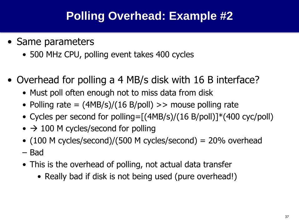
Polling Overhead: Example #2
• Same parameters
• 500 MHz CPU, polling event takes 400 cycles
• Overhead for polling a 4 MB/s disk with 16 B interface?
• Must poll often enough not to miss data from disk
• Polling rate = (4MB/s)/(16 B/poll) >> mouse polling rate
• Cycles per second for polling=[(4MB/s)/(16 B/poll)]*(400 cyc/poll)
• 100 M cycles/second for polling
• (100 M cycles/second)/(500 M cycles/second) = 20% overhead
– Bad
• This is the overhead of polling, not actual data transfer
• Really bad if disk is not being used (pure overhead!)

38
Interrupt-Driven I/O
• Interrupts: alternative to polling
• I/O device generates interrupt when status changes, data ready
• OS handles interrupts just like exceptions (e.g., page faults)
• Identity of interrupting I/O device recorded in ECR
• ECR: exception cause register
• I/O interrupts are asynchronous
• Not associated with any one instruction
• Don’t need to be handled immediately
• I/O interrupts are prioritized
• Synchronous interrupts (e.g., page faults) have highest priority
• High-bandwidth I/O devices have higher priority than low-bandwidth ones

39
Interrupt Overhead
• Parameters
• 500 MHz CPU
• Polling event takes 400 cycles
• Interrupt handler takes 400 cycles
• Data transfer takes 100 cycles
• 4 MB/s, 16 B interface disk, transfers data only 5% of time
• Percent of time processor spends transferring data
• 0.05 * (4 MB/s)/(16 B/xfer)*[(100 c/xfer)/(500M c/s)] = 0.25%
• Overhead for polling?
• (4 MB/s)/(16 B/poll) * [(400 c/poll)/(500M c/s)] = 20%
• Overhead for interrupts?
+ 0.05 * (4 MB/s)/(16 B/int) * [(400 c/int)/(500M c/s)] = 1%
Note: when disk is
transferring data, the interrupt
rate is same as polling rate

40
Direct Memory Access (DMA)
• Interrupts remove overhead of polling…
• But still requires OS to transfer data one word at a time
• OK for low bandwidth I/O devices: mice, microphones, etc.
• Bad for high bandwidth I/O devices: disks, monitors, etc.
• Direct Memory Access (DMA)
• Transfer data between I/O and memory without processor control
• Transfers entire blocks (e.g., pages, video frames) at a time
• Can use bus “burst” transfer mode if available
• Only interrupts processor when done (or if error occurs)

41
DMA Controllers
• To do DMA, I/O device attached to DMA controller
• Multiple devices can be connected to one DMA controller
• Controller itself seen as a memory mapped I/O device
• Processor initializes start memory address, transfer size, etc.
• DMA controller takes care of bus arbitration and transfer details
• So that’s why buses support arbitration and multiple masters!
CPU ($)
Main
Memory Disk
DMA DMA
display NIC
I/O ctrl
Bus

42
I/O Processors
• A DMA controller is a very simple component
• May be as simple as a FSM with some local memory
• Some I/O requires complicated sequences of transfers
• I/O processor: heavier DMA controller that executes instructions
• Can be programmed to do complex transfers
• E.g., programmable network card
CPU ($)
Main
Memory Disk
DMA DMA
display NIC
IOP
Bus

43
DMA Overhead
• Parameters
• 500 MHz CPU
• Interrupt handler takes 400 cycles
• Data transfer takes 100 cycles
• 4 MB/s, 16 B interface, disk transfers data 50% of time
• DMA setup takes 1600 cycles, transfer 1 16KB page at a time
• Processor overhead for interrupt-driven I/O?
• 0.5 * (4M B/s)/(16 B/xfer)*[(500 c/xfer)/(500M c/s)] = 12.5%
• Processor overhead with DMA?
• Processor only gets involved once per page, not once per 16 B
+ 0.5 * (4M B/s)/(16K B/page) * [(2000 c/page)/(500M c/s)] = 0.05%

44
DMA and Memory Hierarchy
• DMA is good, but is not without challenges
• Without DMA: processor initiates all data transfers
• All transfers go through address translation
+ Transfers can be of any size and cross virtual page boundaries
• All values seen by cache hierarchy
+ Caches never contain stale data
• With DMA: DMA controllers initiate data transfers
• Do they use virtual or physical addresses?
• What if they write data to a cached memory location?

45
DMA and Address Translation
• Which addresses does processor specify to DMA controller?
• Virtual DMA
+ Can specify large cross-page transfers
– DMA controller has to do address translation internally
• DMA contains small translation buffer (TB)
• OS initializes buffer contents when it requests an I/O transfer
• Physical DMA
+ DMA controller is simple
– Can only do short page-size transfers
• OS breaks large transfers into page-size chunks

46
DMA and Caching
• Caches are good
• Reduce CPU’s observed instruction and data access latency
+ But also, reduce CPU’s use of memory…
+ …leaving majority of memory/bus bandwidth for DMA I/O
• But they also introduce a coherence problem for DMA
• Input problem
• DMA write into memory version of cached location
• Cached version now stale
• Output problem: write-back caches only
• DMA read from memory version of “dirty” cached location
• Output stale value

47
Solutions to Coherence Problem
• Route all DMA I/O accesses to cache
+ Solves problem
– Expensive: CPU must contend for access to caches with DMA
• Disallow caching of I/O data
+ Also works
– Expensive in a different way: CPU access to those regions slow
• Selective flushing/invalidations of cached data
• Flush all dirty blocks in “I/O region”
• Invalidate blocks in “I/O region” as DMA writes those addresses
+ The high performance solution
• Hardware cache coherence mechanisms for doing this
– Expensive in yet a third way: must implement this mechanism
48
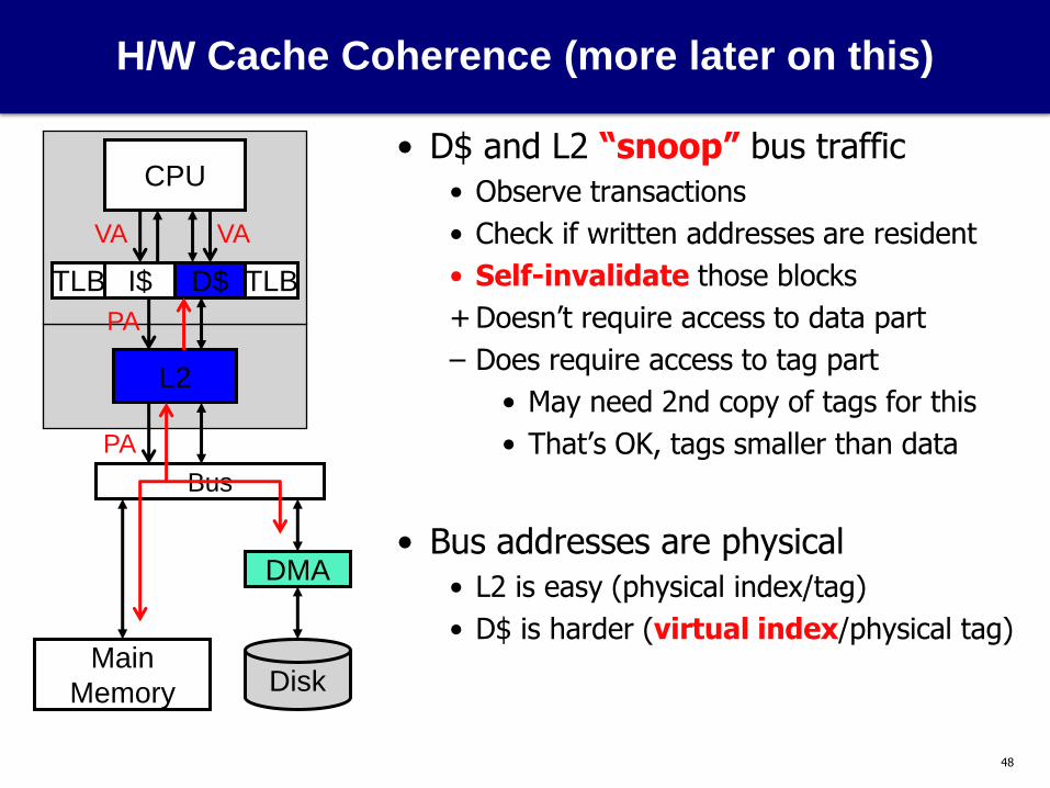
H/W Cache Coherence (more later on this)
• D$ and L2 “snoop” bus traffic
• Observe transactions
• Check if written addresses are resident
• Self-invalidate those blocks
+ Doesn’t require access to data part
– Does require access to tag part
• May need 2nd copy of tags for this
• That’s OK, tags smaller than data
• Bus addresses are physical
• L2 is easy (physical index/tag)
• D$ is harder (virtual index/physical tag)
CPU
D$
L2
I$ TLB
PA
PA
VA VA
TLB
Main
Memory Disk
DMA
Bus

49
Designing an I/O System for Bandwidth
• Approach
• Find bandwidths of individual components
• Configure components you can change…
• To match bandwidth of bottleneck component you can’t
• Example (from P&H textbook, 3rd edition)
• Parameters
• 300 MIPS CPU, 100 MB/s backplane bus
• 50K OS insns + 100K user insns per I/O operation
• SCSI-2 controllers (20 MB/s): each accommodates up to 7 disks
• 5 MB/s disks with tseek + trotation = 10 ms, 64 KB reads
• Determine
• What is the maximum sustainable I/O rate?
• How many SCSI-2 controllers and disks does it require?

50
Designing an I/O System for Bandwidth
• First: determine I/O rates of components we can’t change
• CPU: (300M insn/s) / (150K Insns/IO) = 2000 IO/s
• Backplane: (100M B/s) / (64K B/IO) = 1562 IO/s
• Peak I/O rate determined by bus: 1562 IO/s
• Second: configure remaining components to match rate
• Disk: 1 / [10 ms/IO + (64K B/IO) / (5M B/s)] = 43.9 IO/s
• How many disks?
• (1562 IO/s) / (43.9 IO/s) = 36 disks
• How many controllers?
• (43.9 IO/s) * (64K B/IO) = 2.74M B/s per disk
• (20M B/s) / (2.74M B/s) = 7.2 disks per SCSI controller
• (36 disks) / (7 disks/SCSI-2) = 6 SCSI-2 controllers
• Caveat: real I/O systems modeled with simulation

51
Designing an I/O System for Latency
• Previous system designed for bandwidth
• Some systems have latency requirements as well
• E.g., database system may require maximum or average latency
• Latencies are actually harder to deal with than bandwidths
• Unloaded system: few concurrent IO transactions
• Latency is easy to calculate
• Loaded system: many concurrent IO transactions
• Contention can lead to queuing
• Latencies can rise dramatically
• Queuing theory can help if transactions obey fixed distribution
• Otherwise simulation is needed

52
Summary
• Role of the OS
• Device characteristics
• Data bandwidth
• Disks/SSDs
• Structure and latency: seek, rotation, transfer, controller delays
• Bus characteristics
• Processor-memory, I/O, and backplane buses
• Width, multiplexing, clocking, switching, arbitration
• I/O control
• I/O instructions vs. memory mapped I/O
• Polling vs. interrupts
• Processor controlled data transfer vs. DMA
• Interaction of DMA with memory system