Embed Size (px)
Citation preview

University of Toronto
4/4/2011
ECE352 Digital Systems Design
Final Group Report
Project Title: Interactive Snake Game
Designers: Tang Tang
Qiwei Wang
Lei Wu:
Supervisor: Professor Paul Chow

Project Name: Interactive Snake Game ECE532 Digital Systems Design Final Group Report
University of Toronto, 2011 Date: 4/4/2011 Designers: Tang Tang, Qiwei Wang, Lei Wu
i
Table of Contents 1. Overview ......................................................................................................................................... 1
1.1. Goals and Motivation .............................................................................................................. 1
1.2. Background ............................................................................................................................. 1
1.3. Description of Project ............................................................................................................. 1
1.4. Block Diagram ......................................................................................................................... 2
1.5. Description of IP Cores and Devices ....................................................................................... 2
2. Outcome ......................................................................................................................................... 3
2.1. Review of Original Goals ......................................................................................................... 3
2.2. Review of Work Schedule ....................................................................................................... 4
2.3. Final Product ........................................................................................................................... 6
2.4. Future Improvements ............................................................................................................. 6
3. Description of Blocks ....................................................................................................................... 6
3.1. MicroBlaze Soft Processor (Software) .................................................................................... 6
3.1.1. Overview ......................................................................................................................... 6
3.1.2. Shape/text Drawing ........................................................................................................ 7
3.1.3. Execution of Game Logic ................................................................................................. 8
3.1.4. Interaction with the beacon detection module .............................................................. 9
3.1.5. Interaction with Timer and Interrupt Controller .......................................................... 11
3.1.6. Interaction with Sound Module .................................................................................... 11
3.2. Video_to_ram ....................................................................................................................... 11
3.3. TFT Controller ........................................................................................................................ 11
3.4. MPMC & DDR Memory ......................................................................................................... 11
3.5. PLB Bus Interface of Custom IP ............................................................................................. 12
3.6. Colour Detection Module ..................................................................................................... 13
3.7. Audio Module ....................................................................................................................... 14
4. Description of Design Tree ............................................................................................................ 14
5. Tips and Tricks ............................................................................................................................... 15
6. Conclusion ..................................................................................................................................... 16
7. References .................................................................................................................................... 16

Project Name: Interactive Snake Game ECE532 Digital Systems Design Final Group Report
University of Toronto, 2011 Date: 4/4/2011 Designers: Tang Tang, Qiwei Wang, Lei Wu
1
1. Overview
1.1. Goals and Motivation Being the generation growing up with electrical engineering wonders such as TVs and Internet, we
have had video games being part of our lives for years. While most titles have passed by without
leaving any traces in our memories, some of the games are simply too classical to be forgotten.
Inspired by the recent uprising of motion controlled gaming, our group decided to reproduce one
classic game, Snake, with real-time motion detection as controller on Xilinx XUP Virtex II Pro
Development Board with video decoder peripheral from Digilent. [1]
This document serves as a collective documentation to our design, providing all technical
information required to understand, modify, and/or maintain it. The structure of this document
follows strictly the requirements provide by Professor Chow on the course website for ECE532:
Digital Systems Design [2].
1.2. Background Snake is a classic single player game. In the game, the player controls a long, thin creature,
resembling a snake, to roam around a bordered plane picking up food. Each time the snake eats a
piece of food, its tail grows longer. The game ends whenever the snake’s head hits the border or
itself.
Figure 1: Pictures showing a classical Snake game interface
1.3. Description of Project In this project, our group plans to recreate this game with added features. Our goal is to have the
player hold and move a physical object (acting as a beacon) to attract the movement of the virtual
snake, which is being projected onto a screen. The beacon used in our project is a single red light
emitting diode (LED) at the tip of an extension rod. The goal of the player is to physically move the
beacon to different positions in front of the screen to guide the snake to its food, while at the same
time avoid having the snake hitting itself or the screen border.
Project Name: Interactive Snake Game ECE532 Digital Systems Design Final Group Report
University of Toronto, 2011 Date: 4/4/2011 Designers: Tang Tang, Qiwei Wang, Lei Wu
2
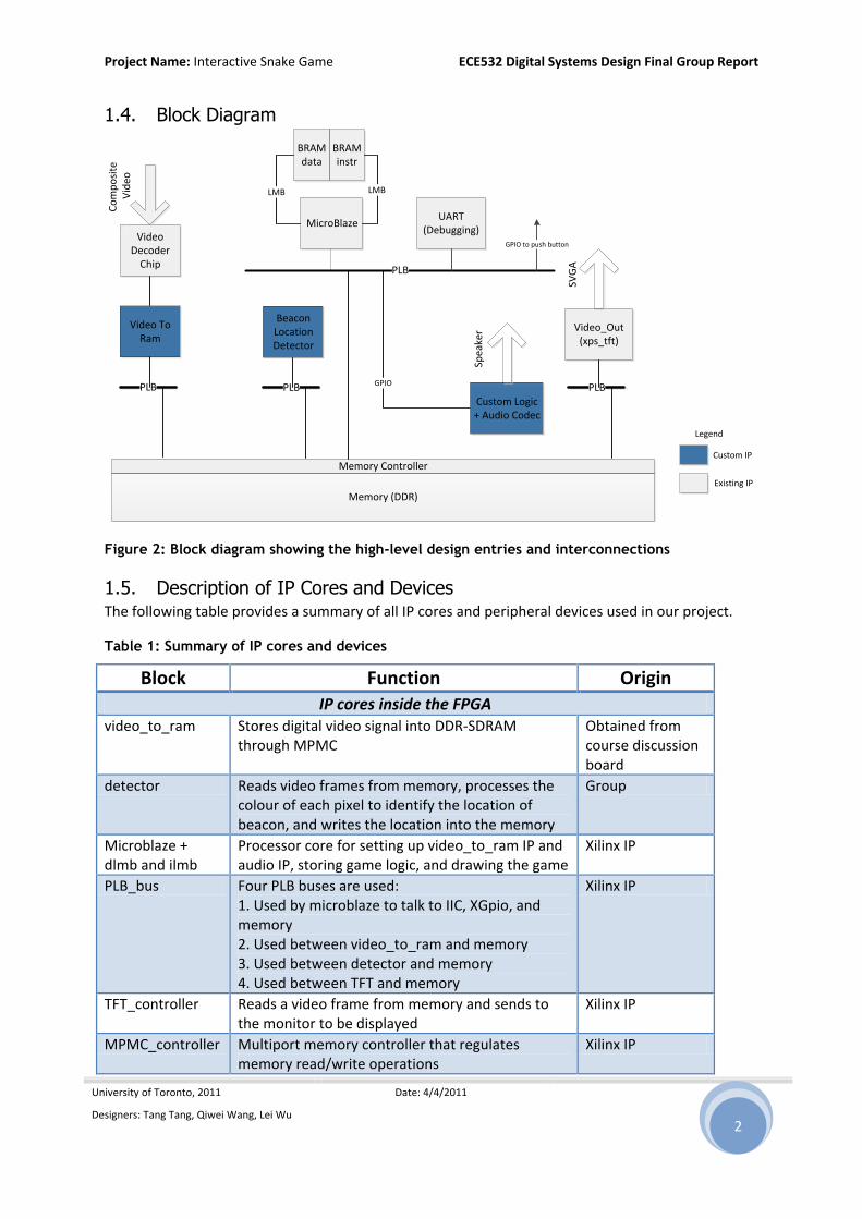
1.4. Block Diagram
Video Decoder
Chip
Video To Ram
Video_Out(xps_tft)
MicroBlaze
Beacon Location Detector
Memory Controller
Memory (DDR)
PLB
Co
mp
osi
te V
ideo
PLB
BRAMdata
BRAMinstr
LMB LMB
SVG
A
GPIO
Custom Logic + Audio Codec
Spea
ker
Legend
Custom IP
Existing IP
PLB PLB
UART(Debugging)
GPIO to push button
Figure 2: Block diagram showing the high-level design entries and interconnections
1.5. Description of IP Cores and Devices The following table provides a summary of all IP cores and peripheral devices used in our project.
Table 1: Summary of IP cores and devices
Block Function Origin IP cores inside the FPGA
video_to_ram Stores digital video signal into DDR-SDRAM through MPMC
Obtained from course discussion board
detector Reads video frames from memory, processes the colour of each pixel to identify the location of beacon, and writes the location into the memory
Group
Microblaze + dlmb and ilmb
Processor core for setting up video_to_ram IP and audio IP, storing game logic, and drawing the game
Xilinx IP
PLB_bus Four PLB buses are used: 1. Used by microblaze to talk to IIC, XGpio, and memory 2. Used between video_to_ram and memory 3. Used between detector and memory 4. Used between TFT and memory
Xilinx IP
TFT_controller Reads a video frame from memory and sends to the monitor to be displayed
Xilinx IP
MPMC_controller Multiport memory controller that regulates memory read/write operations
Xilinx IP

Project Name: Interactive Snake Game ECE532 Digital Systems Design Final Group Report
University of Toronto, 2011 Date: 4/4/2011 Designers: Tang Tang, Qiwei Wang, Lei Wu
3
XGpio Configures the tone_gen audio core, and adds a hardware resets to the game
Xilinx IP
IIC Configures the video decoder Xilinx IP
Timer Controls the rate at which the snake moves Xilinx IP
Interrupt Handler Handles the interrupt request from the timer Xilinx IP
tone_gen Receives audio commands from Microblaze through 8 parallel GPIOs (2 Audio Channels, 4 GIPOs each) and generates sound
Past Project 2010: Human Pong
Devices outside the FPGA
DDR memory The memory stores the incoming video frame, output video frame, and beacon location
Given
Video Camera Captures the video and outputs to the video decode chip
Group
VGA Output video Given
Video Decode chip
Converts the frame by frame composite video signal captured by the camera into digital signal. Digital signal is then fed to the video_to_ram IP block
Given
Speakers Output audio Given
2. Outcome
2.1. Review of Original Goals All primary design goals proposed in the proposal have been met by the time this document is
constructed. These include:
1) Basic game rules including movement of snake, scoring condition and representation (snake
growth), and game over condition detection;
2) Real-time detection and tracking of the beacon;
3) Real-time projection of snake body;
4) “Game Start” and “Game Over” screens;
5) Maintaining an acceptable frame rate so that the game is playable.
Most of the optional goals are also met. These include:
1) Detection of screen size, calibration of the system for beacon location detection;
2) Video effects, including colour and shaping of objects on screen (snake, scoring object, beacon,
screen borders, etc.)
3) Sound effects for events in game such as game start, scoring, and game over;
4) Increasing game difficulty: for every 3 scores the movement speed of snake increases by
approximately 10%;
Some optional goals are modified and/or not implemented in the current version of the system.
These include:

Project Name: Interactive Snake Game ECE532 Digital Systems Design Final Group Report
University of Toronto, 2011 Date: 4/4/2011 Designers: Tang Tang, Qiwei Wang, Lei Wu
4
1) Additional obstacles on screen for increased difficulty: this was not implemented because during
our testing, we found the game actually quite challenging due to the real-time tracking of
beacon as well as the ability for snake make turns of arbitrary angles. Therefore there is no need
to increase the difficulty even further by placing additional obstacles on screen;
2) Difficulty level selection menu at game start screen: this was not implemented because we
found the game challenging enough by gradually increasing snake’s length as well as movement
speed, and therefore there is no need to increase the difficulty of the game further at the
beginning of each game play;
3) Numerical displaying of scoring: this was not implemented because the player’s score was
shown directly through the length of the snake: the longer the snake, the higher the score. And
there is no need to provide additional indicator of player’s score;
4) Automatic pause/resume when beacon is not detected: instead of automatic pause/resume, we
changed the rule so that if beacon suddenly disappears, the last detected beacon location is
recorded as the direction towards which snake moves. And when snake head hit the recorded
location, it stops moving, effectively pausing the game. The modification is much easier to
implement and debug because it does not require any interrupt handling from the video
processing blocks.
In conclusion, our project shows positive result in terms of meeting initial design goals: most of the
features important to game play are implemented and fully tested.
2.2. Review of Work Schedule Throughout the development of the project, our group was able to track our initial weekly
milestones fairly well: before reading week we were even slightly ahead of the schedules on both
hardware and software. During the reading week, our progress was delayed due to an unforeseen
bug in the initialization code of the video block: in our downloaded version the address of video-to-
ram block configuration bits were not set correctly, and we were unable to test our beacon location
detection module until the problem was solved. Also we had some delay in figuring out the PLB
protocol, which collectively delayed our progress by one and a half weeks after the reading week.
After coming back from the break, we consulted the TAs actively, and slightly updated our
milestones according to the situation. Eventually because 1) we put enough buffers in the original
schedule, and 2) 2 other group members worked in parallel on other parts of the design to
compensate for the delay while 1 member debugged the problem, we were able to catch up with
the schedule by the week before demonstration.
Table 2 below provides a summary of proposed milestone and what was actually achieved at each
checkpoint:
Table 2: Comparison of proposed milestone and actual weekly progress
Dates Proposed Weekly Milestones Actual Progress Feb. 2, 2011 Lab Test. Lab Test.
Feb. 9, 2011 VGA video output module completed, able to output coloured screen to monitor; Basic
VGA video output module completed, able to output coloured screen to

Project Name: Interactive Snake Game ECE532 Digital Systems Design Final Group Report
University of Toronto, 2011 Date: 4/4/2011 Designers: Tang Tang, Qiwei Wang, Lei Wu
5
functions of memory controller (MPMC) modules completed and tested, able to read/write data from MicroBlaze processor.
monitor; Basic functions of memory controller (MPMC) modules completed and tested, able to read/write data from MicroBlaze processor. Able to load data from PC to on-board memory.
Feb. 16, 2011
Able to load data from PC to on-board memory, implemented “Game Start” and “Game Over” screens; Start working on Video Decoding module and Video to Ram custom logic.
Implemented “Game Start” and “Game Over” screens on development board; start working on Video Decoding module and Video to Ram custom logic; Able to store captured frames to memory with 2 channels going parallel for read and write; display captured frame on VGA output, i.e. show what’s captured by camera on monitor.
Feb. 23, 2011
(Reading week) (Reading week)
Mar. 2, 2011 Able to store captured frames to memory with 2 channels going parallel for read and write; display captured frame on VGA output, i.e. show what’s captured by camera on monitor; Beacon Location Detection module completed; able to display location of beacon on VGA output; Start C program for snake game on PC.
Working on beacon location detector; started C program for snake game on PC; a simulation of snake game on PC is playable using OpenGL.
Mar. 9, 2011 A preliminary game, “Game Start” screen -> a moving snake -> “Game Over” screen, is playable; able to detect game-over condition (snake head hits screen border or hits other parts of the snake).
Working on beacon location detector; debugging and improved features of snake game on PC simulation, including some optional features such as scoring and increasing snake moving speed.
Mar. 16, 2011
Audio Codec module completed and tested; able to load sound data to memory and play it; audio effects added to the game.
Beacon Location Detection module completed; able to display location of beacon on VGA output; a basic snake game playable implemented and tested.
Mar. 23, 2011
Optional features such as auto calibration (software), multiple difficulty levels (snake moving speed and/or obstacles on map), game pause and resume (game pause and display pause message if cannot find beacon on screen; game resumes when beacon is back) are added to the game; a working game with some bugs is completed.
Audio Codec module completed and tested; audio effects added to the game; started other optional features such as auto calibration; improved UI; a working game with some bugs is completed.
Mar. 30, 2011
ECE Design Fair; All features completed and tested by now. The rest of the term is for additional bug fixes and report writing.
All primary features and most optional features completed and tested.
Apr. 4, 2011 Individual and group reports due. Individual and group reports due.
Apr. 6, 2011 Final demonstration. Final demonstration.

Project Name: Interactive Snake Game ECE532 Digital Systems Design Final Group Report
University of Toronto, 2011 Date: 4/4/2011 Designers: Tang Tang, Qiwei Wang, Lei Wu
6
2.3. Final Product In the end, our system turned out to be quite successful. The game is highly playable with only minor
glitches. The game is quite fun to play especially during later stages of a game – when the snake
becomes long and its movement becomes fast.
2.4. Future Improvements There are quite a number of things that the system could improve upon.
First, currently, there is a visible lag in the beacon detection process. This drawback reduces the
playability of the game somewhat. This is certainly one area that we could improve upon. In addition,
the current beacon is a LED attached to a stick, in the future, we could replace the beacon from a
LED to a laser pointer, where laser pointer location would represent the beacon location. In that
case, the playability of the game should also increase.
The game is currently very rudimentary; there are many additional features that could be added.
Additional features could include: adding obstacles to the canvas to make the game harder, playing
music throughout the game instead of just at game start and game end, allow user to choose
different difficulty levels, etc.
In addition, the graphical user interface can be improved, showing specific instruction and directions
to aid player during the game play. Additional video effects such as background picture for game
board can also be considered.
Last but not least, one interesting feature worth exploring could be making this game multiplayer.
After all, the regular version is mostly single player because there is only one keyboard. Now after
we have made this game interactive, there is no reason why we should limit this game to single
player. We can foresee that it would be very interesting to see several snakes all chasing toward one
food. That would also make the game much more challenging and playable.
If we were to start the project over again, we would implement a different audio module. Currently
the CPU stalls when sound effect is playing because the audio module is in the same thread as the
main game, and the implementation does not include buffer to store sound data to be played. This
also made adding background music to the game impossible. A new module including FIFO buffers
storing instructions to AC’97 audio codec is certainly a plus we would like to see.
3. Description of Blocks
All descriptions provided below are based on documentations of Xilinx EDK/ISE and IP cores of
related blocks. For more information please refer to [3] and [4].
3.1. MicroBlaze Soft Processor (Software)
3.1.1. Overview The MicroBlaze is a built-in soft processor that was created for use in the FPGA by Xilinx. The
processor is automatically included when we start a project in EDK. It is capable of executing C code.

Project Name: Interactive Snake Game ECE532 Digital Systems Design Final Group Report
University of Toronto, 2011 Date: 4/4/2011 Designers: Tang Tang, Qiwei Wang, Lei Wu
7
Due to the nature of this project (an interactive game), we relied on MicroBlaze for many of the core
functionalities: including but not limited to:
1) Shape/text drawing;
2) Execution of game logic;
3) Interaction with the beacon detection module;
4) Interaction with the interrupt controller;
5) Interaction with the sound module.
3.1.2. Shape/text Drawing In this project, we have set the TFT controller to read a predefined chunk of memory in DDR for
display to an external monitor. Each word within this chunk of memory defines the RGB colour of a
pixel. As a result, it is possible for us to directly alter the image to be displayed through software by
writing specific values to words at those particular memory addresses.
At the most fundamental level, we have created an API function write_pixel() which allows the rest
of the program to draw any colour at where on screen. write_pixel() is the function for which all
other drawing functions will invoke.
Clearing Screen
Clearing screen invokes write_pixel(), and the screen is cleared by drawing a white pixel at every
point on screen.
Draw Line
Bresenham’s line algorithm was used to draw a line of any orientation. Detailed description of this
algorithm can be found here: [5].
Draw Rectangle
DrawRectangle function is used to create the border in the snake game. This function invokes
DrawLine function four times, once for drawing each edge of the rectangle.
Draw Circle
Midpoint circle algorithm was used to draw a solid circle. Detailed description of this algorithm can
be found here: [6].
Draw Letter
Similar to drawing of rectangles, letters are drawn by repeatedly invoking DrawLine function, once
for each edge of a letter. Since letters only need to be displayed during game start and game over
screen, only a subset of letters (letters belonging to “GAME START” and “GAME OVER”) need to be
drawn, as a result, the program is capable of drawing only {S, T, A, R, G, M, E, O, V,}. These functions
are robust in that width and size of the letter can be arbitrary.
Draw the Snake
The snake is represented using a linked list. Each element in this linked list represents a segment of
the snake’s body. Each element contains information about the current location of the segment, as
well as pointers to the next element and the last element.

Project Name: Interactive Snake Game ECE532 Digital Systems Design Final Group Report
University of Toronto, 2011 Date: 4/4/2011 Designers: Tang Tang, Qiwei Wang, Lei Wu
8
To make the snake move, location of the head (the first element in the linked list) changes, and then
locations of all the remaining elements will inherit locations of previous element in the linked list.
To make the snake eat, a new element is added to the beginning of the linked list, making it the new
head element.
Drawing the snake is simple. The drawing algorithm goes through all elements of the linked list in
order and draws a circle at the correct location for each segment of the snake’s body. Together
those circles make up the entire snake.
3.1.3. Execution of Game Logic
Snake Move
In contract to the regular snake game, in our implementation, besides moving horizontally and
vertically, the snake could also move in any direction. To attain that effect, the following algorithm
was implemented.
Figure 3: Diagram showing snake movement algorithm
Suppose the snake wants to move toward the beacon as shown in the above figure. And suppose
that we would want the snake to move an increment of dh=10 at a time in that direction. We can
calculate the new head location (x0’, y0’) through the following way.
Given beacon location (x1,y1) and snake head location (x0,y0), we can calculate {h,x,y} as shown in
the diagram. Then from similar triangles, we can find that the value of dx and dy are:
From there, we can calculate (x0’, y0’)

Project Name: Interactive Snake Game ECE532 Digital Systems Design Final Group Report
University of Toronto, 2011 Date: 4/4/2011 Designers: Tang Tang, Qiwei Wang, Lei Wu
9
Food Generation
A food, represented by a green circle is generated randomly on screen. This algorithm is reinvoked
once the snake has succeeded in eating the current food.
Food Detection
There are two global variables (storing values of (x,y) ) keeping track the location of the current food.
As the snake moves, the program detects whether the food is directly in front of the snake by
comparing the location of the head with location of the food. If it is, the food is considered to be
eaten. The current food will be erased and a new food will be generated.
Game-over Condition Detection
The game ends whenever the snake hits the border or itself. The program detects game over
condition by checking whether any pixel directly in front of the snake is blue since the both the
border and the snake are blue coloured.
3.1.4. Interaction with the beacon detection module
Detection
The program needs to know the location of the beacon in order to guide the movement of the snake.
The beacon detection module continuously calculates three values:
1) The sum of x coordinates of all possible beacon locations. (x_sum)
2) The sum of y coordinates of all possible beacon locations. (y_sum)
3) The number of the possible beacon locations. (count)
For details of how those values are obtained, please refer to the description of the colour detection
algorithm presented in sections that follow.
From software perspective, the location of the beacon (x,y) can be calculated:
Calibration
The location of the beacon calculated above represents a location in the camera’s frame. In order to
make the snake move toward the beacon precisely, we need to transform that location into the
screen frame.

Project Name: Interactive Snake Game ECE532 Digital Systems Design Final Group Report
University of Toronto, 2011 Date: 4/4/2011 Designers: Tang Tang, Qiwei Wang, Lei Wu
10
Figure 4: diagram showing the frame structure during calibration
For example, in the above figure, given the location of the beacon in the camera frame (ub, vb), we
need to transform it into the correct location in the screen frame (xb,yb).
To do that, we need to first identify the transformation matrix. Before the game is playable, the
program will first calibrate itself by displaying four red circles, as shown below. Since the program
already knows the (x,y) coordinates of those red circles and the program is able to obtain the (u,v)
locations of those circles through the beacon detection module, we could obtain four (u,v) < -> (x,y)
pairs to build the transformation matrix.
Figure 5: diagram showing the calibration algorithm

Project Name: Interactive Snake Game ECE532 Digital Systems Design Final Group Report
University of Toronto, 2011 Date: 4/4/2011 Designers: Tang Tang, Qiwei Wang, Lei Wu
11
From those pairs, we can calculate, {dx,dy} and {du,dv}. Then given a point (u,v) in the camera frame,
we can calculate its location (x,y) in the screen frame through the following transformation.
3.1.5. Interaction with Timer and Interrupt Controller To make the playing experience consistent, we need to implement a reliable delay function. The
delay function was used partially to dictate the difficulty of the game. For example, the delay
function was used to vary the speed at which the snake would move. Interrupt was used to achieve
this purpose. Once invoked, the delay function starts an interrupt and then keeps polling on a global
variable that the interrupt handling routine will update. Once a time is reached, delay function is
exited.
3.1.6. Interaction with Sound Module Audio APIs are called when a sound effect needs to be played. CPU gives tone information, i.e. pitch
and length of the note, to the sound module, which then creates the waveform and gives commands
to the AC’97 decoder block. For more information please refer to the description of the sound
module.
3.2. Video_to_ram The video_to_ram IP block was obtained from the course discussion board. This block stores digital
video signal into the memory, and in our project, memory location 0x40000000 - 0x401FFFFF with
frame size of 1024 x 512, with valid pixel data frame size of 640 x 480.
3.3. TFT Controller The XPS TFT controller is an IP block in the Xilinx IP library. It acts as the PLB master of one PLB bus
that is connected to the MPMC. It reads the video data from a range of memory locations, and in our
project, the base address is 0x41000000. It then converts these video data to VGA compatible data
that is available to display on the monitor. It also acts as a slave to the MicroBlaze, the processor
could change the base memory location that the TFT controller displays by writing to a slave register.
This speeds up the debugging process as we can either display our game or the captured video by
writing to a slave register in the XMD stub.
3.4. MPMC & DDR Memory The MPMC (multi-port memory controller) is an IP block in the Xilinx IP library. It allows up to 8
buses to be connected to the same memory through different ports. In this project, we used a total
of 4 ports in the MPMC:
Port 0: used by the Microblaze to write hardware configurations and read important slave registers Port 1: used by the video_to_ram IP block to write video frame to the memory. Port 2: used by the TFT controller to display the video frame to the monitor by reading from the memory.

Project Name: Interactive Snake Game ECE532 Digital Systems Design Final Group Report
University of Toronto, 2011 Date: 4/4/2011 Designers: Tang Tang, Qiwei Wang, Lei Wu
12
Port 3: used by the detector (custom IP) to read incoming video frame and colour bound configurations, and write detector location to the memory.
3.5. PLB Bus Interface of Custom IP The custom IP uses the PLB bus to communicate with the MPMC. To ensure the correct functionality
of the custom IP, it has to be able to do both write and read operations to the memory. Two
separate finite state machines (FSM) are implemented: write FSM and read FSM. The state diagrams
for both write and read FSM are shown below. The state diagrams were created with reference for
PLB bus write and read timing diagrams shown in [7] and [8]. All states will return to the INIT state
upon system reset, which is not shown for neatness reasons. Two FSM will not request to access the
memory at the same time because of the register r_nw. A post-processing state is added after the
read complete state to update the custom logic's internal registers.
R_INIT
This is the state coming out of system reset
R_READ_REQUEST
Issues write request to the PLB
R_READ
Waits for the write complete signal from the PLB
R_READ_COMPLETE
Write is completed, issues another write only under
specific conditions
MPMC_Done_init = 1
i_S1_addrAck = 1 and i_PLB_PAValid = 1
i_PLB_MRdDAck = 1
R_POST_READ_PROCESSWrite is completed, issues another write only under
specific conditions
r_nw = 1
always
i_S1_addrAck = 0 ori_PLB_PAValid = 0
i_PLB_MRdDAck = 0
r_nw = 0
MPMC_Done_init = 0
READ FSM
Figure 6: Read FSM state transition diagram for PLB bus interface

Project Name: Interactive Snake Game ECE532 Digital Systems Design Final Group Report
University of Toronto, 2011 Date: 4/4/2011 Designers: Tang Tang, Qiwei Wang, Lei Wu
13
S_INIT
This is the state coming out of system reset
S_WRITE_REQUEST
Issues write request to the PLB
S_WRITE
Waits for the write complete signal from the PLB
S_WRITE_COMPLETE
Write is completed, issues another write only under
specific conditions
MPMC_Done_init = 1
i_S1_addrAck = 1 and i_PLB_PAValid = 1
i_S1_wrComp = 1
r_nw = 0
i_S1_addrAck = 0 ori_PLB_PAValid = 0
i_S1_wrComp = 0r_nw = 1
MPMC_Done_init = 0
WRITE FSM
Figure 7: Write FSM state transition diagram for PLB bus interface
3.6. Colour Detection Module Since the CPU requires only three values (sum of x-coordinates, sum of y-coordinates, and number
of points on the frame) at a slow refresh rate (maximum once per frame, or approximately 10
frames-per-second), the colour detection module can be implemented quite easily. The module
basically scans through the frame data provided by video-to-ram module, and counts how many
points fall within the colour range specified, while recording the x-coordinate and y-coordinate of
the points.
Specifically, the flow of the algorithm can be described as below:
1) Starting at the first pixel of the video-to-ram, initialize all register variables, which includes the 3
output values, as well as all the state-related variables;
2) Read from memory the colour upper bound and colour lower bound of the pixels to be detected.
This operation is performed once at the beginning of every frame processed to enable detection
of different colours in software, as well as to avoid confusion in cases the boundary values are
changed in the middle of a frame;
3) For all pixels in the range of video-to-ram output addresses, determine first if the pixel is a valid
pixel representing contents captured by camera. Then determine whether all three colours (red
green and blue) fall within the range specified by the colour upper bound and colour lower
bound. If so, increment pixel_count, add the current x-coordinate value to the x_cord_sum and
the current y-coordinate value to the y_cord_sum;
4) When it reaches the end of video-to-ram output range, the colour detection module outputs
three data: x_cord_sum, y_cord_sum, and pixel_count to memory location 0x49210000,

Project Name: Interactive Snake Game ECE532 Digital Systems Design Final Group Report
University of Toronto, 2011 Date: 4/4/2011 Designers: Tang Tang, Qiwei Wang, Lei Wu
14
0x49210004, and 0x49210008 respectively. The addresses were picked arbitrarily in the unused
address range in the memory;
5) Return to the first pixel, loop back to 1).
Margin on valid pixel range to avoid noises
When determining whether a specific pixel falls within the range of valid pixels from camera, we give
some extra margin in addition to the 640-by-480 range. Specifically we count only the 630-by-470
block of pixels in the middle of each frame, throwing out 5 pixels along each screen edge. The reason
was because we observed black pixels (0x0) and sometimes even random noises along the edges
inside the frame. If the noise happens to fall within the colour detection range, the algorithm would
yield incorrect results. Given that most of the time beacon will not be at the screen edges, we decide
to put a safety margin of 10 pixels on each coordinates to improve the system performance.
Colour replacement for debugging
Our module also has hard-coded colour replacement feature for debugging purposes: instead of
processing the pixels internally, we can configure the IP core to output all pixels read, with desired
beacon colours being replace by an arbitrary value. Because in the module we use only single-beat
read and write on PLB, the refresh rate can be significantly limited when performing such colour
replacement. However by directing the video output module to display the frame after colour
replacements, we can easily debug the system by seeing whether the desired the pixels are detected
and replaced. This feature requires one addition write to PLB after each read, and therefore is
turned off in our final product to increase the refresh rate of beacon location detection.
3.7. Audio Module The audio module is ported directly from last year’s project: Human Pong [9]. Some modifications on
software were made for better integration with our system.
The module includes two main parts: controller, or the tune generator, and the AC’97 codec. An
example of AC’97 codec with documentation of the chip used on board can be found at [10]. The
controller is connected to MicroBlaze CPU through 8 parallel GPIOs for 2 audio channels, 4 signal
lines for each channel (32-bit tone period and duration, 1-bit begin and done pins). When receiving
data from the CPU, the controller averages (essentially, performs mixing of) data from the two
channels and produces a square waveform according to the tone periods and durations given. The
produced waveform is then fed into AC’97 codec to produce sound at the audio output of the
development board.
By using parallel GPIOs, driver implementation of the audio module becomes trivial: simply sending
data over GPIO with GPIO driver does the job. A wrapper function in C is written to simplify the
process of generating sound in software.
4. Description of Design Tree
This section illustrates the content of every folder that we have submitted regarding our project. A
README file has also been included at the top level of our directory for the same purpose.

Project Name: Interactive Snake Game ECE532 Digital Systems Design Final Group Report
University of Toronto, 2011 Date: 4/4/2011 Designers: Tang Tang, Qiwei Wang, Lei Wu
15
Table 3: Description of design tree
Folder Name Description System This folder contains the XPS project
Our custom pcores are stored in the directory \pcores Our C code is stored in the directory \sw Key files include: 1. detector.v - contains the code to perform read/write operations to the PLB bus, and custom logic to identify the beacon location by the use of color bounds of pixels. --> \System\pcores\detector_v1_00_a\hdl\verilog\detector.v 2. video_setup.c - configures the video decode chip --> \System\sw\video_setup.c 3. audio_setup.c - configures the audio hardware --> \System\sw\ audio_setup.c 4. snake.c - contains the game logic --> \System\sw\snake.c 5. draw.c - contains the functions to display the game by writing to memory locations --> \System\sw\ draw.c 6. main.c - all the above c files are copied to the main function to reduce microblaze bram usage. --> \System\sw\ main.c
Doc This folder includes all the documentations for our project Project Proposal: Project_proposal.pdf Group Report: Group_report.pdf Power Point of our presentation - Final_Presentation.pdf
5. Tips and Tricks
One thing we found particularly helpful during our design procedure was that, by making copies of
each week’s working project, we were able to maintain a series of ready-to-demonstrate projects
with incremental progresses. This was helpful especially when something goes wrong during the
coming week’s development, because it is usually difficult, and sometimes even impossible to
completely revert a change in project settings and/or compilation options. For a few times our group
had to roll back the entire design to a previously functional block to proceed in a different direction.
This may not be a good source control practice, but we found it helpful for a relatively small project
like what we are doing here.
Project Name: Interactive Snake Game ECE532 Digital Systems Design Final Group Report
University of Toronto, 2011 Date: 4/4/2011 Designers: Tang Tang, Qiwei Wang, Lei Wu
16
6. Conclusion
This document provides a comprehensive technical documentation to our group’s design
“Interactive Snake Game” for ECE532: Digital Systems Design. Most if not all details related to our
design including concepts, decisions, methods, etc. are described and explained. Based on these
discussions, we also made conclusion to our design in general as well as suggestions for future
improvements.
7. References
[1] Paul Chow. (2011, January) ECE532S: Digital Systems Design. [Online].
http://www.eecg.toronto.edu/~pc/courses/532/2011/
[2] ECE532 Digital Systems Design. (2011, January) ECE532S Project Demos and Reports.
[3] Xilinx, Inc. (2011, April) Xilinx.com. [Online]. http://www.xilinx.com/
[4] Xilinx, Inc. (2011, April) Xilinx XUPV2P Documentations. [Online].
http://www.xilinx.com/univ/xupv2p.html
[5] Wikipedia.org. (2011, April) Bresenham's Line ALgorithm. [Online].
http://en.wikipedia.org/wiki/Bresenham's_line_algorithm
[6] Wikipedia.org. (2011, April) Midpoint Circle Algorithm. [Online].
http://en.wikipedia.org/wiki/Midpoint_circle_algorithm
[7] IBM Corp. (2007, May) IBM 128-Bit Processor Local Bus Architecture Specifications Version 4.7.
[Online]. https://www-
01.ibm.com/chips/techlib/techlib.nsf/techdocs/3BBB27E5BCC165BA87256A2B0064FFB4/$file/Pl
bBus_as_01_pub.pdf
[8] Xilinx, Inc. (2010, December) Xilinx PLBV46 Master Burst (1.01a) Documentation. [Online].
http://www.xilinx.com/support/documentation/ip_documentation/plbv46_master_burst.pdf
[9] Chris Langan, Kevin Lam, and Nancy Chong. (2011, January) ECE532 Digital Systems Design Past
Projects. [Online]. http://www.eecg.toronto.edu/~pc/courses/532/2011/pastprojects.html
[10
]
Xilinx, Inc.; Eric Gallimore; Nathaniel Smith; Mark Chang. (2006, April) AC'97 Audio Codec
Controller for Digilent XUP-V2P. [Online]. http://embedded.olin.edu/xilinx_docs/projects/audio-
v2p.php