Embed Size (px)
Citation preview

notes, M. Rodwell, copyrighted
ECE145A / 218A Notes :Basic Analysis of Analog Circuits
Mark RodwellUniversity of California, Santa Barbara
[email protected] 805-893-3244, 805-893-3262 fax

notes, M. Rodwell, copyrighted
Comment
This (2009) is a transitional year:
Next year 145abc will be reorganizedNext year 145abc will be reorganized,145a: fundamentals (devices, analog & RF analysis, models)145cb: RF systems at IC and system level
This year:some students have taken 145c:
l d h d i d lalready have device modelsalready know analog circuit analysis well
some students have notmust cover device modelsmust review some circuit analysis methods
These notes: shortened version (2009 only) of device models

notes, M. Rodwell, copyrighted
Transistor Circuit Design
This note set
-reviews the basics-starts at the level of a first IC design course-starts at the level of a first IC design course -moves very quickly
This will
establish a common terminology-establish a common terminology-accommodate capable students having minimal background in ICs.

notes, M. Rodwell, copyrighted
DC d lDC modelsDC bi l iDC bias analysis

notes, M. Rodwell, copyrighted
Large-Signal Model For Bias Analysis
IcIb
Vbe
+ -
,0 that Provided ceV >
resistanceemitterthetointernalspecifiedisthatnote/ where,/ and )/exp(
,
TcbTbesc
ce
RVqkTVIIVVII === β
d ititttiHBTfti ifiidTh
resistanceemitter thetointernalspecified is that note... exbe
RI
RV
bandwidth.istor peak transfor requirednear that densitiescurrent at operatingHBTsfor t significan is drop The exeRI

notes, M. Rodwell, copyrighted
DC Bias Example: Current Mirror
refI
1Q2Q
2cI
)()(haveWe 22221111 bb RRIVRRIV ++=++
2exR
2eeR
1exR
1eeR1eI2eI
2bI 1bI
)/ln( ,)/ln( and)()( have We
222111
22221111
sctbesctbe
eeexebeeeexebe
IIVVIIVVRRIVRRIV
==++++
area)emittertheis(thatassume&2 ,1 that Assume 12 eeee
AAARR
==>>β
2and2/impliesThis
area).emitter theis( that assume & 21 EEE
IIRR
AAA
==
=
2/ find which wefrom,2and,2/ implies This
12
2121
cc
ssexex
IIIIRR
===

notes, M. Rodwell, copyrighted
Simpler DC Model for Bias Analysis
IcIb
IcVbe
Ib
Vbe
==takeinsteadandwithofvariation theignore toanalysis biasin sufficientoften isIt
φbbb VVIV
t h ldd ittd d
. takeinsteadandwith ofvariation , φonbebecbe
V
VVIV
bias,bandwidth peak of 10%~ within densitiescurrent at Biasedy. technologanddensity current upon depends ,onbeV
⎪⎨
⎧= HBTsInGaAs/InPV9.0or 7.0
HBTs Si/SiGeModern V 9.0~φonbeV⎪⎩
⎨HBTs GaAs/GaInP V .41
, φonbe

notes, M. Rodwell, copyrighted
Simple DC Bias Example
I I 1
Rc
Ib2 Ib1
Q2 Q1
Rb
Ree
-Vee
ee
bbbb
VVVVRI
(SiGe). V 9.0 eApproximat Volts. 0 then drops, eneglect th weIf
21
21
−≅−====
φ
eeeeccc
ee
RVVIIRVVIII
2/)90(/)9.0(2
21
121
21
−−==−−==+
eeeecc RVVII 2/)9.0(21

notes, M. Rodwell, copyrighted
Efficiently Handling Base Currents In Bias Analysis
:equationsussimultaneosolvecanonet,singifican is drop If bbRI
I Ib1
Rc
/where/)(2
:equationsussimultaneo solve can one
1121
βφ eebbeeccc
IIRRIVIII −−−==+
Ib2 Ib1
Q2 Q1
Rb
it tibfi dQ i k
,/ where 11 βcb II =
Ree
1
2/)( solve 1):iterationby find :Quicker
1 φ eeeec RVI −−=-Vee
2/)( solve to of value thisuse 3)/ solve 2)
11
11
φβ
eebbeecb
cb
RRIVIIII
−−−=≅ ee
bias DChascircuit designed-any well because Works. upondependent y only weakl β

notes, M. Rodwell, copyrighted
ll i lsmall-signal b b d l ibaseband analysis

notes, M. Rodwell, copyrighted
Hybrid-π Bipolar Transistor Model
Ccbx
CcbiRbbB CRc
bf τ+τ=τ R Vbe gmVbee-jωτcmbe gR /β=
cbf τ+τ=τ Rbe
R
be
CCb diff =g τ f
gm be
ERexCje
Cbe,diff gmτ f
Accurate model, but too detailed for quick hand analysis

notes, M. Rodwell, copyrighted
Oversimplified Model for Quick Hand Analysis
bemVg
+
beRbeC bemVg
+
beRB BC C
cbC
beV+
−beV+
−
In most high frequency circuits the node impedance is low and
E E
In most high-frequency circuits, the node impedance is low and Rce is therefore negligible.
Neglecting Rbb in high-frequency analysis is a poor approximationNeglecting Rbb in high frequency analysis is a poor approximation but is nevertheless common in introductory treatments.
The "textbook" analyses which follow use this oversimplified model. These introductory treatments will later be refined. y

notes, M. Rodwell, copyrighted
Common Emitter Stage: Basics
LeqRCLeqC IRV δδ ⋅−= )2
/)5 βδδ b II =
q
)(/ )7 , eebbTin RrIVR +== βδδ/)5 βδδ cb II
ce II δδ ≅ )1+mebe gIV / )4 δδ =
δδ)3
−
eEe IRV δδ ⋅=)3
)()( )6 eebeeeb RrIRrIV +⋅=+⋅= βδδδ EReebeeeb
)/1/()/( / / )8 meLeqeeLeqBoutinout gRRRrRVVVV +−=+−== δδδδ
)( is Transistor ; )/1/(- isGain EeinmeLeq RrRgRR ++ β

notes, M. Rodwell, copyrighted
Emitter Follower Stage: Basics
/)4 βδδ cb II =
)(/ )6 , LeqebbTin RrIVR +== βδδ/) βδδ cb
ce II δδ ≅ )1+mebe gIV / )3 δδ =
IRV δδ)2
−
eLeqe IRV δδ ⋅=)2
)()( )5 LeqebLeqeeb RrIRrIV +⋅=+⋅= βδδδ LeqRqq
)/1/()/( / / )7 mLeqLeqLeqeLeqEoutinout gRRRrRVVVV +=+== δδδδ
)( is Transistor ; )/1/( isGain EeinmLeqLeq RrRgRR ++ β

notes, M. Rodwell, copyrighted
Common-Base Stage: Basics
CLeqout IRV δδ ⋅=)2)/( )6 βδδ beein RrIV +⋅=
βδδ //)7 RIVR βδδ // )7 , BeeeTin RrIVR +==
mebe gIV / )5 δδ =ce II δδ ≅ )1
+−
LeqRBR
/ )3 βδδ cb II = / )4 βδδ bcb RIV ⋅=
cb
)//( / )7 βδδ beLeqinout RrRVV +=
ββ / is Transistor ; )//( isGain beinbeLeq RrRRrR ++

notes, M. Rodwell, copyrighted
Emitter Follower Output ImpedanceECE145C /218C notes, M. Rodwell, copyrighted
Common-Base Stage: Basics
CLeqout IRV δδ ⋅= )2)/( )6 βδδ beein RrIV +⋅=
βδδ // )7 , BeeeTin RrIVR +==
BRemitteroutR ,
ampoutR ,
mebe gIV / )5 δδ =ce II δδ ≅ )1
LeqR
+−
BR
B
/ )3 βδδ cb II =
)//( / )7 βδδ beLeqinout RrRVV +=
/)4 βδδ bcb RIV ⋅=
EERββ /isTransistor;)//(isGain beinbeLeq RrRRrR ++EE
impedanceinput C.B. as problem same is impedanceoutput E.F.
ββ //1/, BmBeemitterout RgRrR +=+=
RRR EEemitteroutampout RRR ,, =

notes, M. Rodwell, copyrighted
Including Bias Circuit Resistances
CRLCLeq RRR =1BR
TinR ,
1BRinTBBAmpin RRRR 21, =
LRgenR inV
1BRV
t i tith thll lidd d)(t i i llTh
1BRgenV
.impedancescircuit net thedetermine toimpedances terminalrtransistowith theparallelin added )(trivially are These
etc. , )/(/ which,From ,, genampinampingenin RRRVV +=

notes, M. Rodwell, copyrighted
Baseband Analysis Of Multistage Circuits
Q Q
For baseband analysis of multi-stage circuits, simply break into individual stages.
Q2Q1 Q4
Q3 Load impedance of the Nth stage includes the input impedance of the (N+1)th stage
Analysis is then trivialAnalysis is then trivial...
Rin4Rin3Rin2
Vout2
Q2Q1 Q4
Q3Vin1
in4
Vout1
out2Vout3
R
Rin3
Vin2=Vout1 Rin4
Vout2=Vin3Vout3=Vin4
Rin2Vin2 Vout1 Rin4

notes, M. Rodwell, copyrighted
ll i lsmall-signal b b d l ibaseband analysis
notes, M. Rodwell, copyrighted
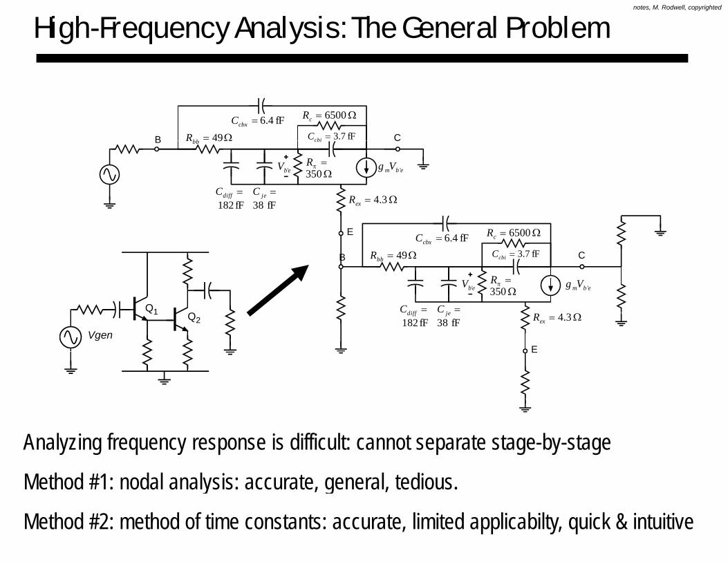
High-Frequency Analysis: The General Problem
fF4.6=cbxCfF3.7=cbiCΩ= 49bbR
Ω= 6500cR
B C
ebmVg '
cbiΩ49bbR
Ω= 3.4exR
ebV '
B C
=diffCfF182
=jeCfF38
=πRΩ350
E fF4.6=cbxCfF3.7=cbiCΩ= 49bbR
Ω= 6500cR
VV
B C
=R
Ω= 3.4exR
ebmVg 'ebV '
E
=diffCfF182
=jeCfF38
=πRΩ350
Q2Q1
VgenE
Analyzing frequency response is difficult: cannot separate stage-by-stage
Method #1: nodal analysis: accurate, general, tedious.y , g ,
Method #2: method of time constants: accurate, limited applicabilty, quick & intuitive

notes, M. Rodwell, copyrighted
N d l A l iNodal Analysis
notes, M. Rodwell, copyrighted
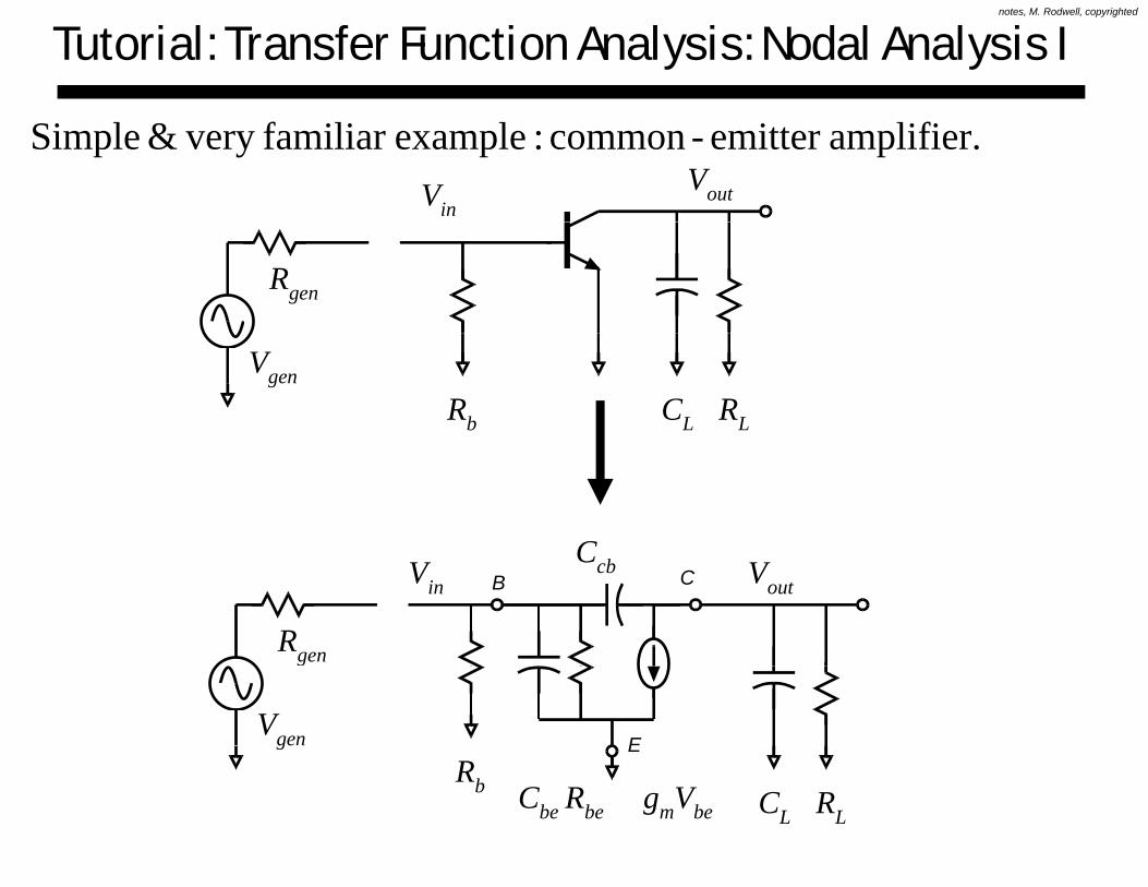
Tutorial: Transfer Function Analysis: Nodal Analysis I
amplifier.emitter -common :examplefamiliar very & SimpleVin
Vout
Rgen
RLCLRb
Vgen
CB C
Rgen
Vin VoutCcb
ER
Vgen
RLCL
Rb gmVbeRbeCbe

notes, M. Rodwell, copyrighted
Tutorial: Transfer Function Analysis: Nodal Analysis II
:circuit Reduced Vin Vout
)||||( bbegeni RRRR =
RLCLRiIi=Vgen/Rgen gmVbe
Cbe
KCLfrom EquationsNodal Write :1 Step
⎥⎤
⎢⎡
=⎥⎤
⎢⎡⎥⎤
⎢⎡ −++ iincbcbbei IVsCsCsCG
⎥⎦
⎢⎣
⎥⎦
⎢⎣⎥⎦
⎢⎣ ++− 0outcbLLcbm VsCsCGsCg

notes, M. Rodwell, copyrighted
Tutorial: Transfer Function Analysis: Nodal Analysis III
inout sDsNIV = )(/)(/: EquationsNodal Solve :2 Step
cbmcbm
cbbei sCgsCg
sCsCGsN −−=
−++
= )(01
)(
cbLLcbm
cbcbbei
sCsCGsCgsCsCsCG
sD++−
−++=)(
cbLLcbmg
( )( ) ( )( ))( cbcbmcbLLcbbei sCsCgsCsCGsCsCGsD −−−++++= ( )( ) ( )( )
ofpowersinOrganize:3Step
)( cbcbmcbLLcbbei
s
g
()(
ofpowers in Organize :3 Step
Li
CgCGCGCGCGsGGsD
s
+++++=
)(
( 2
cbcbcbcbLcbcbbeLbe
cbmcbLbeLcbiLi
CCCCCCCCCCs
CgCGCGCGCGs
−++++
+++++

notes, M. Rodwell, copyrighted
Tutorial: Transfer Function Analysis: Nodal Analysis IV
.function..transfer thefromgainsandconstants separating form, spolynomial-of-ratio essdimensionl into Separate :4 Step
==)()(
/
gp g
gengen
out
in
out
sDsN
RVV
IV
⎟⎞
⎜⎛ +++++
−−=
()(
)(
bbLbLbiLiLi
cbm
gengenin
CgCGCGCGCGsGGsCg
⎟⎟⎠
⎞⎜⎜⎝
⎛
+++
+++++
)(
(2
LcbcbbeLbe
cbmcbLbeLcbiLiLi
CCCCCCs
CgCGCGCGCGsGG
/)( −− genLicbmout RRRsCgV
)(
(1
2 ⎟⎟⎠
⎞⎜⎜⎝
⎛
+++
+++++=
LiLcbcbbeLbe
cbLimcbibeicbLLL
g
gen
out
RRCCCCCCs
CRRgCRCRCRCRsV
)( ⎠⎝ LiLcbcbbeLbe

notes, M. Rodwell, copyrighted
Tutorial: Transfer Function Analysis: Nodal Analysis V
)||()||()||||(
that note,
,
+=
+==
genAmpin
Ampin
genbbe
bbe
gen
genbbe
gen
i
RRR
RRRRR
RRRR
RR
so...,
⎟⎞
⎜⎛
gpggg
RV ( )
)/1(
,
, −⎟⎟⎠
⎞⎜⎜⎝
⎛
+= Lm
genAmpin
Ampin
gen
out
C
RgRR
RVV
1a1b
)(
)(1)/1(
2 ⎟⎟⎞
⎜⎜⎛ +++++
−−×
cbLimcbibeicbLLL
mcb
CRRgCRCRCRCRsgsC 1a
)( 2 ⎟
⎠⎜⎝ +++ LiLcbcbbeLbe RRCCCCCCs
2a
11
)()(
21
sasasb
VV
sVsV outout
+++
=⇒
1)( 21 sasaVsVbandmidgengen ++
−

notes, M. Rodwell, copyrighted
Tutorial: Transfer Function Analysis: Nodal Analysis VI
11)( 11 sbVsbVsV ++
polynomial theofzeros)&(polesroots the Find:5 Step
)/1)(/1(1
11
)()(
21
12
21
1
ppbandmidgen
out
bandmidgen
out
gen
out
sssssb
VV
sasasb
VV
sVsV
−−+
=++
+=
−−
?polesthefindingofmethodsefficientarewhat ?poles thefindingofmethodsefficient arewhat

notes, M. Rodwell, copyrighted
Fi di P lFinding Poles f T f F tifrom Transfer Functions

notes, M. Rodwell, copyrighted
Finding Poles and Zeros
1)(
: FormPolynomial-of-Ratio2sbsbVsV +++
...1...1*
)()(
221
21
band-midat
m
gen
out
gen
out
sasasbsbs
VV
sVsV
++++++
=
:Zeros and Poles
).../1)(/1)(/1().../1)(/1)(/1(*
)()(
111
111
ppp
zzzm
gen
out
gen
out
sssssssssssss
VV
sVsV
−−−−−−
=))()(()( 111band-midat pppgengen

notes, M. Rodwell, copyrighted
Finding Poles: Complex Poles
++++++
=out
sasasasbsbk
VV
1...1
32
221
⎟⎟⎞
⎜⎜⎛ +++
≈
<<
+++
out
gen
sbsbkV
saaa
sasasaV
...1
and sfrequencie moderateat theignore can we then/ If
1
221
3223
321
⎟⎟⎠
⎜⎜⎝ ++
≈gen
out
sasak
V
thencomplexarethisofrootstheIf
1 221
21
nωdjω
⎟⎟⎠
⎞⎜⎜⎝
⎛+++++
=⎟⎟⎠
⎞⎜⎜⎝
⎛++
+++=
nngen
out
sssbsbk
sasasbsbk
VV
ωωζ /)/2(1...1
1...1
thencomplex, are thisof roots theIf
22
221
221
221
nζω
⎟⎟⎟⎟⎞
⎜⎜⎜⎜⎛
⎟⎞
⎜⎛⎟⎞
⎜⎛
+++=out
sssbsbk
VV ...1 2
21 )1( 222 ζωω −= nd
⎟⎟⎠
⎜⎜⎝
⎟⎟⎠
⎞⎜⎜⎝
⎛−−
+⎟⎟⎠
⎞⎜⎜⎝
⎛+−
−dndn
gen
js
jsV
ωζωωζω11

notes, M. Rodwell, copyrighted
Finding Poles: Separated Pole Approximation
then,)/( e.g. separated widely are roots theIf
112 aaa <<
1...1
,)(g
2
221
112
sasasbsbk
IVout
⎟⎟⎠
⎞⎜⎜⎝
⎛++
+++=
ωj
...1
12
21
21
sbsbkI
V
sasaI
out
in
⎞⎛ ⎞⎛+++
≅
⎠⎝ ++
σ12 / aas −=
( ) 111
21 s
aasa
Iin
⎟⎟⎠
⎞⎜⎜⎝
⎛⎟⎟⎠
⎞⎜⎜⎝
⎛++
σ1as −=
pole.dominant theis 1a

notes, M. Rodwell, copyrighted
I t d tIntroductory Ci it D iCircuit Design: summary

notes, M. Rodwell, copyrighted
Gain Stages: Elementary Bandwidth Analysis
Using the oversimplified device model below, with Cpi denoting the sum of base-emitter depletion and diffusion capacitances, bandwidth of CE/CB/CC stages can be found….g
VRC C
V
bemVg
+
beRbeCB C
cbC
beV−
EE

notes, M. Rodwell, copyrighted
CE Stage: Elementary Bandwidth Analysis
RgenRL
CL
Rc
RL
Rin
Ri is the parallel combination of Rgen, Rin, and Rpi
RLeq is the parallel combination of RL, Rc, and Ro
Note in the dominant pole (a1) the miller-multiplication of the collector base capacitancecapacitance

notes, M. Rodwell, copyrighted
CC Stage: Elementary Bandwidth Analysis
RgenCL
RinREE
RL
Ri is the parallel combination of Rgen, and Rin,
RLeq is the parallel combination of Ree and RL
Note that the frequency response is a mess. Given CL, the transfer function very often has complex poles and may show strong gain peaking hencevery often has complex poles, and may show strong gain peaking, hence ringing in the pulse response.

notes, M. Rodwell, copyrighted
CB Stage: Elementary Bandwidth Analysis
Rgen Rcc
RL
CL
bmjecbin gCC τ+=,
RinRgen Rcc
RL
CLCin,cb CcbVin
V
kTqIjg ω =/)(
Rin
RL
Rin gm*Vin
Vgen
cm j
jgωτ
ω+
=1
)(
Here we have a problem. To the extent that the CB stage is modeled by a very very simple hybrid-pi model (explicitly, with zero Rbb), we find (by very simple analysis) very high bandwidth with poles having time constants equal to tau banalysis) very high bandwidth, with poles having time constants equal to tau_b, to tau_c, and to the product of the load resistance times (Ccb+CL).
Note that1) I i i i d d d D i l d ff f1) Input capacitance is indeed as noted. Does not include effect of tau_c
2) Ignoring Rbb in CB stage analysis, while appealing for simplicity (e.g. undergrad classes) is quite unreasonable, as CcbRbb often dominates g ) q ,high frequency rolloff. More regarding this later.
notes, M. Rodwell, copyrighted
M th d fMethod ofTi C t tTime Constants
notes, M. Rodwell, copyrighted
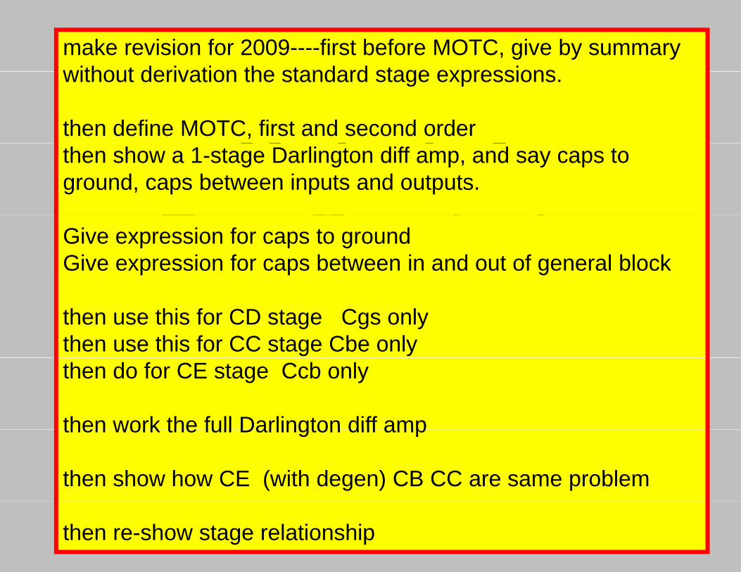
make revision for 2009----first before MOTC, give by summary without derivation the standard stage expressions
M th d f
without derivation the standard stage expressions.
then define MOTC, first and second order
Method ofTi C t t
then show a 1-stage Darlington diff amp, and say caps to ground, caps between inputs and outputs.
Time ConstantsGive expression for caps to groundGive expression for caps between in and out of general block
then use this for CD stage Cgs onlythen use this for CC stage Cbe onlythen do for CE stage Ccb only
then work the full Darlington diff ampthen work the full Darlington diff amp
then show how CE (with degen) CB CC are same problem
then re-show stage relationship

notes, M. Rodwell, copyrighted
Finding Bandwidth: Method of Time Constants
ebmVg '
fF4.6=cbxCfF3.7=cbiCΩ= 49bbR
Ω= 6500cR
ebV '
B C
=πRebmg
Ω= 3.4exR
eb'
E
=diffCfF182
=jeCfF38
Ω350
fF4.6=cbxCfF3.7=cbiCΩ= 49bbR
Ω= 6500cR
B C
Q2Q1
Vgen
Ω= 3.4exR
ebmVg 'ebV '
E
=diffCfF182
=jeCfF38
=πRΩ350
take a general RC network (no inductors or delays tau), and separate into 2 parts, network without capacitors, and the capacitors:

notes, M. Rodwell, copyrighted
MOTC: Separation into Capacitors & Resistive N-port
The internal capacitor-free network is now frequency-independent The MOTC method (not proven here) relies onindependent. The MOTC method (not proven here) relies on results from n-port network theory

notes, M. Rodwell, copyrighted
MOTC: Open-Circuit Resistances
i hdii lllhi0
by determined is This circuited.-open portsother allwithoneport at measuredresistancesignal small theis 0
11R
e)(or voltagcurrent resulting the thisfromcomputingandport at thecurrent)(or age test volta applying

notes, M. Rodwell, copyrighted
MOTC: the Dominant Time Constant
theus givedirectly constants order time-first MOTC The
dB-3 the,negligible is constant timesecondary theif)only (andIf circuit.theofconstant imedominant t
2
1
aa
. determine toconstants timecircuit)-(shortorder -second theusemust We.2/1 isbandwidth
2
1
aaπ

notes, M. Rodwell, copyrighted
MOTC: Are We Saving Any Work ?
Are we saving work relative to brute-force nodal analysis:MOTC would be of only moderate value if we had to calculateMOTC would be of only moderate value if we had to calculateall the Ri's each time. Fortunately, most terms involve quantities already found in midband stage analysis: input and output impedances, load impedances, etc.

notes, M. Rodwell, copyrighted
MOTC: Short-Circuit Resistances
circuited,-openportsotherall withoneport at measured resistance signal small theis 2
11R
shorted is which 2,port for except circuited,open portsother all

notes, M. Rodwell, copyrighted
MOTC: The Second-Order Time-Constant

notes, M. Rodwell, copyrighted
MOTC: Working these Efficiently
inchoices2havealwaysweBecause 00 RRRR xy =
work the tois trick The MOTC. in the each term finding
in choices2have alwayswe, Because RRRR yyxxyyyxx =
impedancesloadouput,input,torelated are terms1):possible asmuch as that so problem
willIoften thatsoarisewhichcasesfunny""2areThereanalysis. in earlier, found ones are terms2)
ppp)
1a
)illkllhl d intimately are these(note pages 2next on the themgive
willIoften thatso arisewhich casesfunny 2 are There
effect)Miller known - well the torelated

notes, M. Rodwell, copyrighted
MOTC and the Miller Effect
outviyxx RARR ++= )1( outvixx )(
outRvARiR
C
RoutRvA
iR[ ] CRARa •++== )1(τ [ ] CRARa outvi •++== )1(1 τ

notes, M. Rodwell, copyrighted
MOTC: port impedances between collector and base
xR parallel thedenote tois that explicitly decide weIf
Leq
be
RR
ofeffect combined thedenotessimilarly that and , and sresistancecircuit externalany ofn combinatio
LeqLeqmxyy
ce
RRgRR
R
++= )1(
then , and resistors external0
LeqLeqmxyy g )(

notes, M. Rodwell, copyrighted
MOTC: Port Impedances Between Emitter & Base

notes, M. Rodwell, copyrighted
MOTC: Multistage Example
work on the board...

notes, M. Rodwell, copyrighted
E dEnd