Embed Size (px)
Citation preview

ECE 312 Electronic Circuits (A)
Lec. 4: BJT Circuits & Troubleshooting
Instructor
Dr. Maher Abdelrasoul
1
Outline
Various BJT Circuits
Troubleshooting Techniques
2
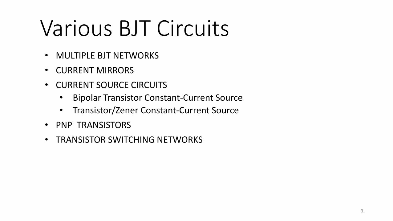
Various BJT Circuits• MULTIPLE BJT NETWORKS
• CURRENT MIRRORS
• CURRENT SOURCE CIRCUITS
• Bipolar Transistor Constant-Current Source
• Transistor/Zener Constant-Current Source
• PNP TRANSISTORS
• TRANSISTOR SWITCHING NETWORKS
3

Multiple BJT Networks (1 of 6)
4
• R–C coupling

Multiple BJT Networks (2 of 6)
5
• Darlington configuration

Multiple BJT Networks (3 of 6)
6
RE

Multiple BJT Networks (4 of 6)
7
• Feedback Pair

Multiple BJT Networks (5 of 6)
8
• Direct Coupled

9
Multiple BJT Networks (6 of 6)

Current Mirrors (1 of 2)
10
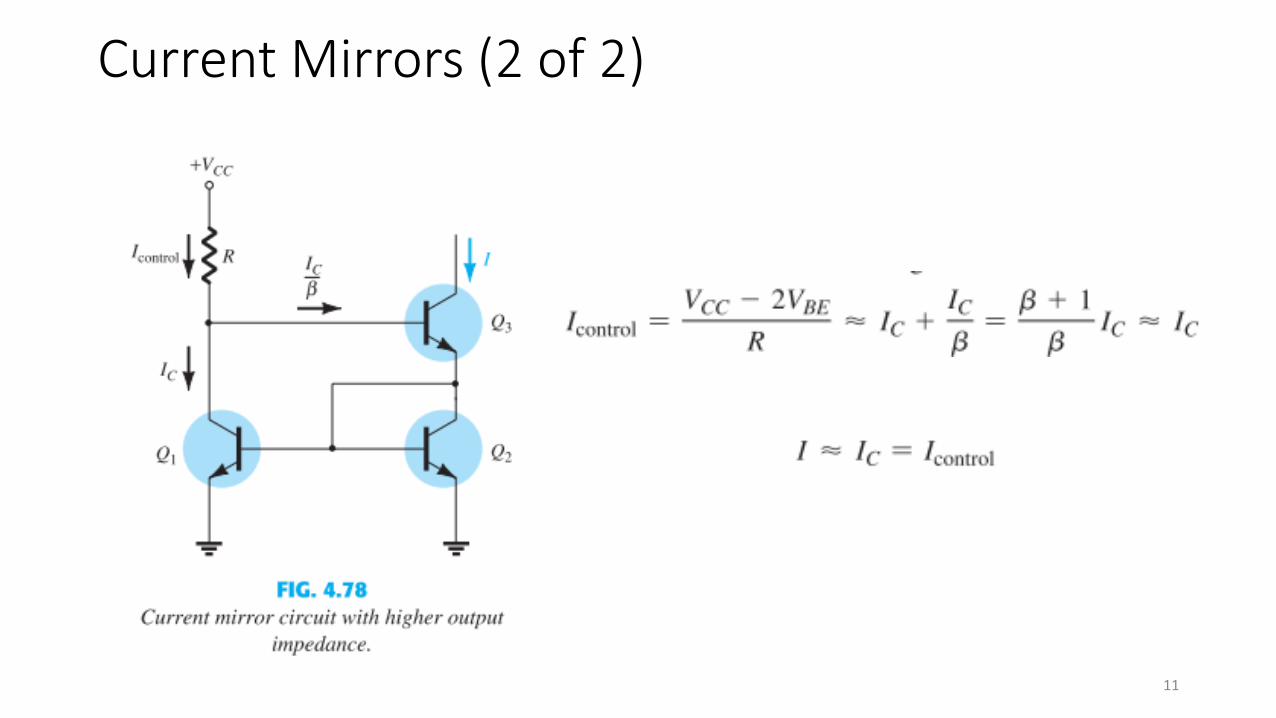
Current Mirrors (2 of 2)
11

Current Source Circuits (1 of 2)
12
Bipolar Transistor Constant-Current Source Transistor/Zener Constant-Current Source

Current Source Circuits (2 of 2)
13

PNP Transistors (1 of 2)
14
• The analysis thus far has been limited totally to npn transistors.• Fortunately, the analysis of pnp transistors follows the same
pattern established for npn transistors. • In fact, the only difference between the resulting equations for
a network in which an npn transistor has been replaced by a pnp transistor is the sign associated with particular quantities.

PNP Transistors (2 of 2)
15
Write the equations of solution

16
Transistor Switching Networks (1 of 3)

Transistor Switching Networks (2 of 3)
17

Transistor Switching Networks (3 of 3)
18

Troubleshooting Techniques
• For an “on” transistor, the voltage VBE should be in the neighborhood of 0.7 V.
• For the typical transistor amplifier in the active region, VCE is usually about 25% to 75% of VCC .
19

20