Embed Size (px)
Citation preview

ECDIS Training Kit NZS-35
Instruction Manual for Windows 7/10
Contents
1 Overview ..................................................................................................................... 1
2 System Diagrams ......................................................................................................... 1
2.1 Simulator ............................................................................................................................ 1
3 ECDIS Software........................................................................................................... 2
3.1 Start ECDIS Software......................................................................................................... 2
3.2 Shut down ECDIS Software ............................................................................................... 3
4 Simulator ..................................................................................................................... 5
4.1 Start the Simulator Software .............................................................................................. 5
4.2 Shut down the Simulator Software ..................................................................................... 6
4.3 Simulator screen. ................................................................................................................ 7
4.4 GPS1 Tab ........................................................................................................................... 8
4.5 GYRO Tab ....................................................................................................................... 10
4.6 SONAR Tab ..................................................................................................................... 11
4.7 DEPTH Tab ..................................................................................................................... 12
4.8 Auto Pilot Tab .................................................................................................................. 13
4.9 FILE Tab .......................................................................................................................... 14
5 Sample data ............................................................................................................... 16
5.1 Sample data of AIS ........................................................................................................... 16 5.1.1 Folder of AIS1 ....................................................................................................................... 16 5.1.2 Folder of AIS2 ....................................................................................................................... 16 5.1.3 Folder of AIS3 ....................................................................................................................... 16
5.2 Sample data of TT1/TT2 ............................................................................................... 16
5.3 Sample data of NAVTEX.................................................................................................. 16
6 Appendix A : Sample data of AIS(Folder of AIS3) .................................................... 18

7ZPNA4757
1
1 Overview On a PC with this training kit installed, it is possible to operate ECDIS basic function such as chart
installation / update, route planning and navigation monitoring. The data of sensor are transmitted to client PC to Master PC. It is possible to operate route monitoring and collision avoidance as similar as actual operation using ECDIS software in PC.
2 System Diagrams Connection examples of this equipment are shown below.
Note : Simulator is installed in the Master PC only.
2.1 Simulator Simulator create and transmit the data of sensor. ECDIS Software receive the data of sensor through the network. Simulator ECDIS software
(GPS/Gyro/Log etc..)
Transmit the data of sensor
-Route planning -Display of ship’s information -User map

7ZPNA4757
2
3 ECDIS Software
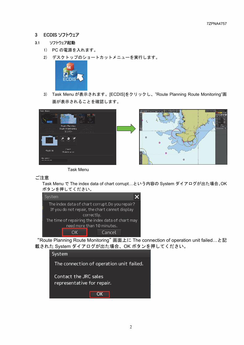
3.1 Start ECDIS Software 1) Turn on the PC. 2) Execute “ECDIS” desktop shortcut. 3) Task Menu is displayed and select ECDIS button. Note: If System dialog (The index data of chart corrupt…) is displayed in Task Menu, click OK button.
Note: If System dialog (The connection of operation unit failed…) is displayed in Route Planning Route Monitoring screen, click OK button.
ECDIS
Task Menu

7ZPNA4757
3
3.2 Shut down ECDIS Software
1) Select the [Menu]- [ ].
2) Click the [Code Input].
3) Input “9999” and then click Enter.
4) Task Menu is displayed. Click Password.
Input “9999”

7ZPNA4757
4
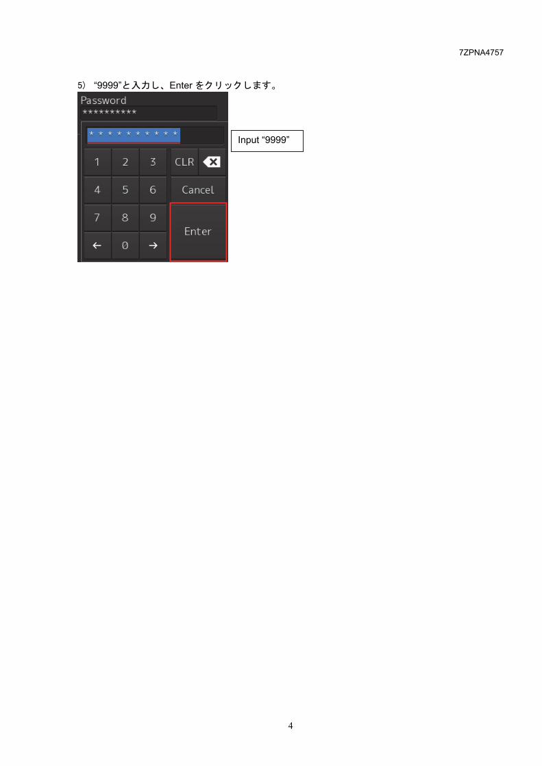
5) Input “9999” and then click Enter.
Input “9999”
7ZPNA4757
5
4 Simulator
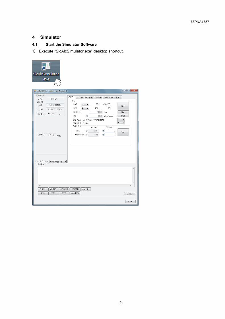
4.1 Start the Simulator Software
1) Execute “SlcAlcSimulator.exe” desktop shortcut.

7ZPNA4757
6
4.2 Shut down the Simulator Software
1) Click of the Exit button or the [×] button.
2) Click [OK] button. The Simulator Software will be shut down.

7ZPNA4757
7
4.3 Simulator screen.
A. MONITOR UTC (hh mm ss), Latitude, Longitude, speed and heading are displayed.
B. Local Datum
Local Datum can be set the following local datum “W84:WGS84”, “W72:WGS72”, “S85:SGS85”, “P90:PE90”, “999:user defined”
C. SET
SET button. SET can be set the transmit data. Please refer to the next page.
D. EXIT Shut down button. When EXIT button was clicked, the Simulator Software will be shut down.
A
B
C
D

7ZPNA4757
8
4.4 GPS1 Tab
(1) LAT, LON (Setting of longitude and latitude) Select Latitude north or south (N/S), Longitude east or west(E/W). Input Longitude and Latitude value. When SET button is clicked, transmit value will be change. (2) SPEED (Setting of ship’s speed) Input speed value. When SET button is clicked, transmit value will be change. (3) ROT Not used.
(1)
(2)
(3)
(4)
(6)
(5)

7ZPNA4757
9
(4) $GPGGA GPS Quality indicate (Setting of GPS quality indicator of GGA sentence) Select the following quality indicator.
0: Fix not available or invalid 1: GPS, SPS mode, fix valid (GPS) 2: Differential GPS, SPS mode, fix valid (DGPS) 3: GPS, SPS mode fix valid 4: Real time kinematics. Satellite system used in RTK mode with fixed integers 5: float RTK. Satellite system used in RTK node with floating integers 6: Estimated (dead reckoning) mode 7: Manual input mode
8: Simulator mode (5) $GPGLL Status (Setting of status of GLL sentence) Select the data status.
A: Data valid V: Data invalid
(6) Course True Offset for the true direction over ground and the ship's heading. (Settable to -180 to 180) Magnetic Offset for the magnetic direction over ground and the ship's heading. (Settable to -180 to 180)

7ZPNA4757
10
4.5 GYRO Tab
(1) BEARING Input BEARING value. When SET button is clicked, transmit value will be change. (2) BEARING+ (Rate of turn and direction of turn) Input BEARING+ value. When SET button is clicked, transmit value will be change. (3) Mode Indicator Select Mode Indicator of $HETHS sentence.
A: Autonomous E: Estimated (dead reckoning) M: Manual input S: Simulator mode V: Data not valid (including standby)
(1)
(2)
(3)

7ZPNA4757
11
4.6 SONAR Tab
(1) Water (VBW sentence) Input the ship speed through the water (Longitudinal and Transverse). When SET button is clicked, transmit value will be change. (2) Water speed Status (VBW sentence) Select the data status.
A: Data valid V: Data invalid
(3) Ground (VBW sentence) Input the ship speed over ground (Longitudinal and Transverse). When SET button is clicked, transmit value will be change. (4) Ground speed Status (VBW sentence) Select the data status.
A: Data valid V: Data invalid
(5) SET, DRIFT(VDR sentence) Input a current flows (set) and speed (drift) of a current value. When SET button is clicked, transmit value will be change.
(1) (2)
(3) (4)
(5)

7ZPNA4757
12
4.7 DEPTH Tab
(1) Transducer(DPT, DBT and DBS sentence) Input Water depth relative to the transducer. When SET button is clicked, transmit value will be change. (2) Surface(DPT and DBS sentence) Input the offset of the measuring transducer. When SET button is clicked, transmit value will be change. (3) Ships Floor(DBK sentence) Input the depth below keel. When SET button is clicked, transmit value will be change.
(1)
(2)
(3)

7ZPNA4757
13
4.8 Auto Pilot Tab
(1) AP Mode Select the steering mode of the autopilot.
(1)

7ZPNA4757
14
4.9 FILE Tab
(1) Route Transmit GPS data from the route file. Procedure 1.Click button. 2.Select the route file. Then the route file name is displayed. 3.Click check box. Then Simulator start to transmit GPS data according to the route file.
3
(1)
2 1
(2)
(3)
(4)

7ZPNA4757
15
(2) AIS / TT1 / TT2 Transmit AIS, TT data from the log file.
Procedure 1. Click button. 2. Select the log file. Then the route file name is displayed 3. Input the interval for transmission. e.g.) Interval : 100 msec Log file : 10 lines Data transmission time : 100 [msec] × 10 [lines] = 1 [s] 4. Click check box. Then Simulator start to transmit the data according to the log file. (3) NAVTEX Transmit NAVTEX data from the log file.
Procedure 1. Click button. 2. Select the log file. Then the route file name is displayed 3. Click button. Then Simulator send one NAVTEX data from log file. (4) NAVTEX (Binary) Not used.
1 4
1 2
3
2
3

7ZPNA4757
16
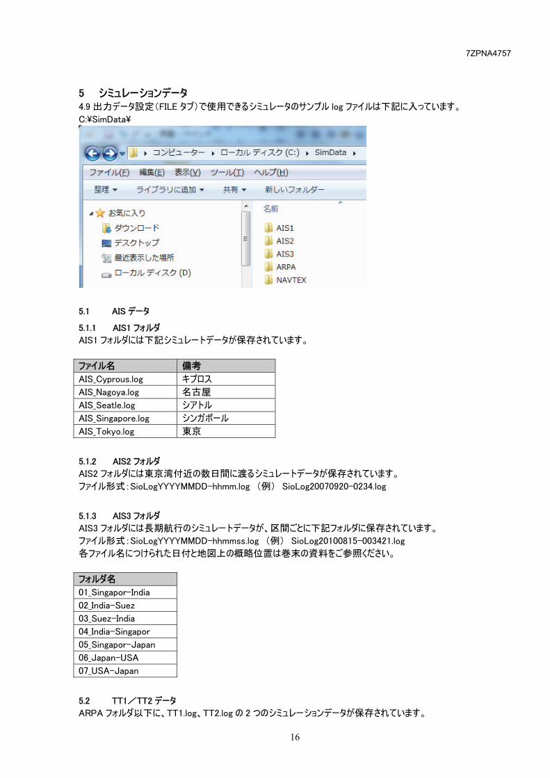
5 Sample data Sample data is installed the following path in MASTER PC. (Please refer to 4.9 FILE Tab how to use the log file.) C:¥SimData¥
5.1 Sample data of AIS
5.1.1 Folder of AIS1 Folder of AIS1 are installed the following sample data. File name Location AIS_Cyprous.log Cyprous AIS_Nagoya.log Nagoya in Japan AIS_Seatle.log Seatle in USA AIS_Singapore.log Singapore AIS_Tokyo.log Tokyo in Japan
5.1.2 Folder of AIS2 Folder of AIS2 are installed the several days of AIS data around Tokyo Bay. File name format : SioLogYYYYMMDD-hhmm.log For example) SioLog20070920-0234.log
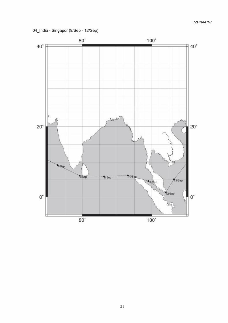
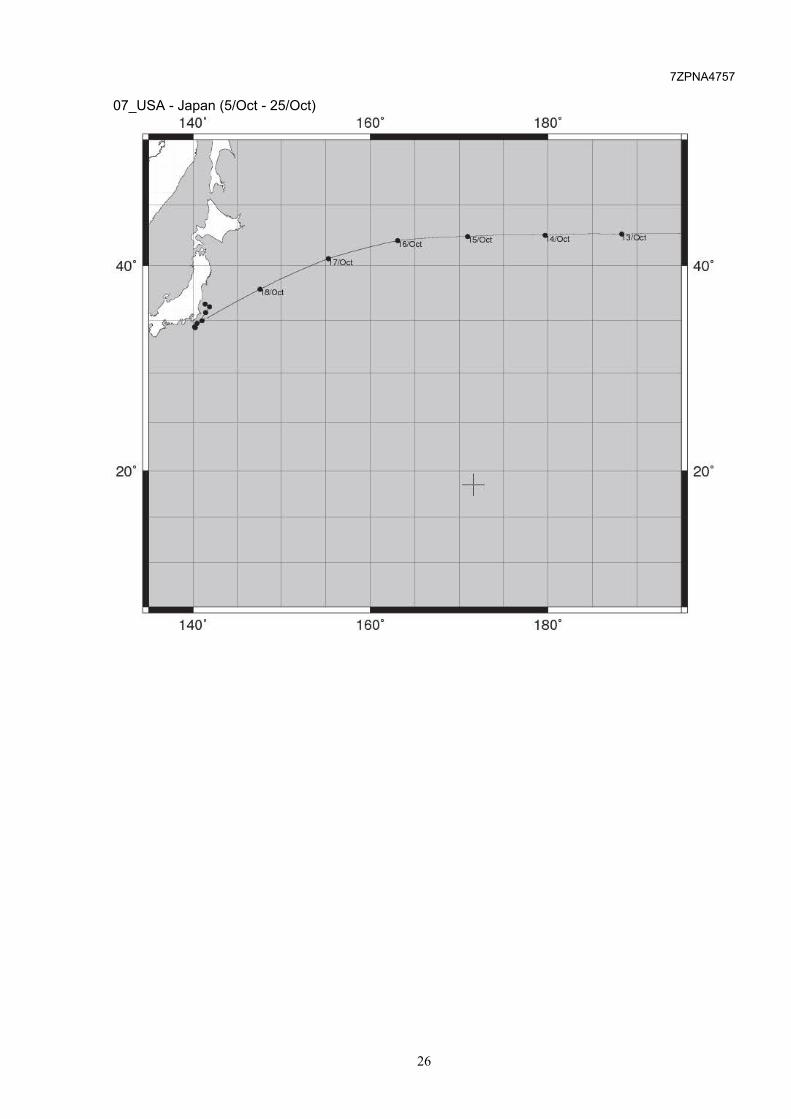
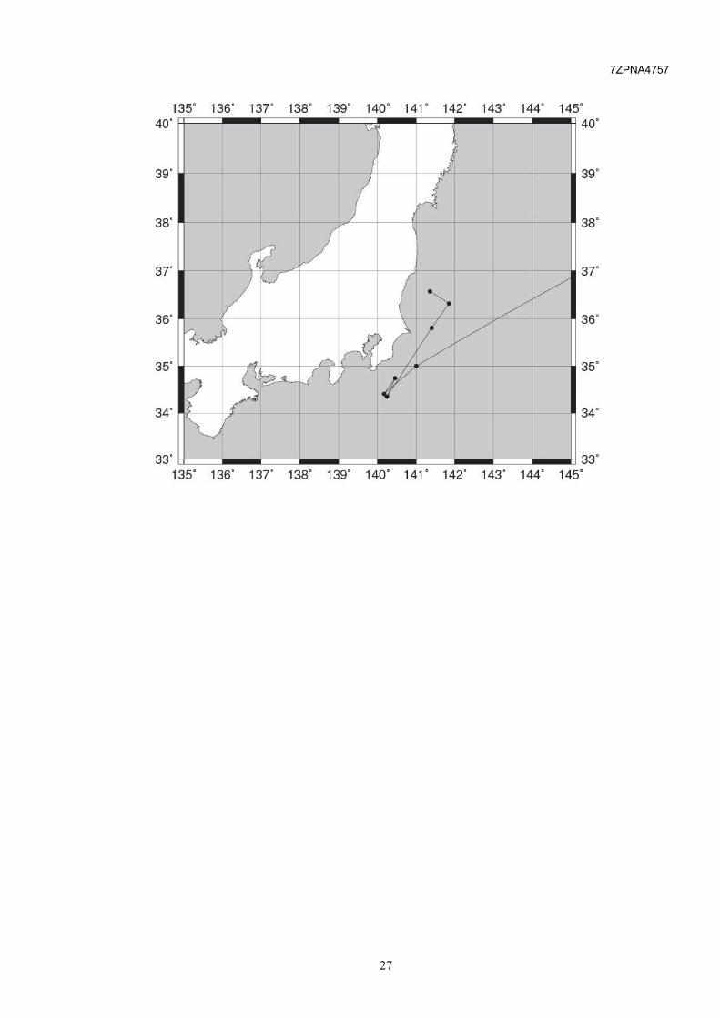
5.1.3 Folder of AIS3 Folder of AIS3 are installed AIS data for the long navigation of ship. File name format : SioLogYYYYMMDD-hhmmss.log For example) SioLog20100815-003421.log Please refer to Appendix A for more information. Folder Name 01_Singapor-India 02_India-Suez 03_Suez-India 04_India-Singapor 05_Singapor-Japan 06_Japan-USA 07_USA-Japan
5.2 Sample data of TT1/TT2 Folder of ARPA are installed the following sample data. These data arrange a radar target in an arc around the ship. Folder Name TT1.log TT2.log
5.3 Sample data of NAVTEX Folder of NAVTEX are installed the following sample data.

7ZPNA4757
17
When ECDIS receives NAVTEX data, ECDIS will displays MSI mark on the chart. Note : Please use NAVTEX_NMEA.log. NAVTEX.log is not supported by this training kit. Folder Name NAVTEX.log NAVTEX_NMEA.log NAVTEX_NMEA.log (15 NAVTEX data is included) PA74 NAVTEX TEST DATA No.1 NETHERLANDS COASTGUARD NAVIGATIONAL WARNING NR74 211600UTCJAN PLATFORM L13-FD-1 53-15.5N004-14.5E UNLIT AC16 NAVTEX TEST DATA No.2 35-06N,139-20E KW67 NAVTEX TEST DATA No.3 19-06.800N, 156-28.387W TK36 NAVTEX TEST DATA No.4 39-21.507N,125-54.743W JA52 NAVTEX TEST DATA No.5 42-36.662S, 129-26.826E PC85 NAVTEX TEST DATA No.6 34-29N,135-05E UV16 NAVTEX TEST DATA No.7 33-21N,135-05W NE71 NAVTEX TEST DATA No.8 75-10.331N, 173-31.928W 75-10.510N,173-32.012W GD62 NAVTEX TEST DATA No.9 67-53.706S, 76-24.655E
YG08 NAVTEX TEST DATA No.10 15-18.280N,82-23.620E PA74 NAVTEX TEST DATA No.11 33-16N,132-15E AC16 NAVTEX TEST DATA No.12 31-03N,130-03E KW67 NAVTEX TEST DATA No.13 57-45.494N,84-28.627W 57-45.502N, 84-28.965W 57-45.400N, 84-29.000W TK36 NAVTEX TEST DATA No.14 25-58N,127-52W JA52 NAVTEX TEST DATA No.15 0-50.532S,18-45.973E NNNN

7ZPNA4757
18
6 Appendix A : Sample data of AIS(Folder of AIS3) 01_Sigapor - India (15/Aug - 21/Aug)
80' 100' 40' R==::::::;::==~-..---.--.--~===;===t:~ 40'
20' 20'
+
+
9lA~~ll/IIJ-~7fAu
0' + 0'

7ZPNA4757
19
02_India - Suez (22/Aug - 31/Aug)
40. 60.
o·

7ZPNA4757
20
03_Suez - India (1/Sep - 8/Sep)
40. 60. 40
20'
o·
40. 60. so·
7ZPNA4757
21
04_India - Singapor (9/Sep - 12/Sep)
40. r====r===~aro~· ---r----r----r--~~==~==~ 1 oo· 40.
ao· 1 oo·

7ZPNA4757
22
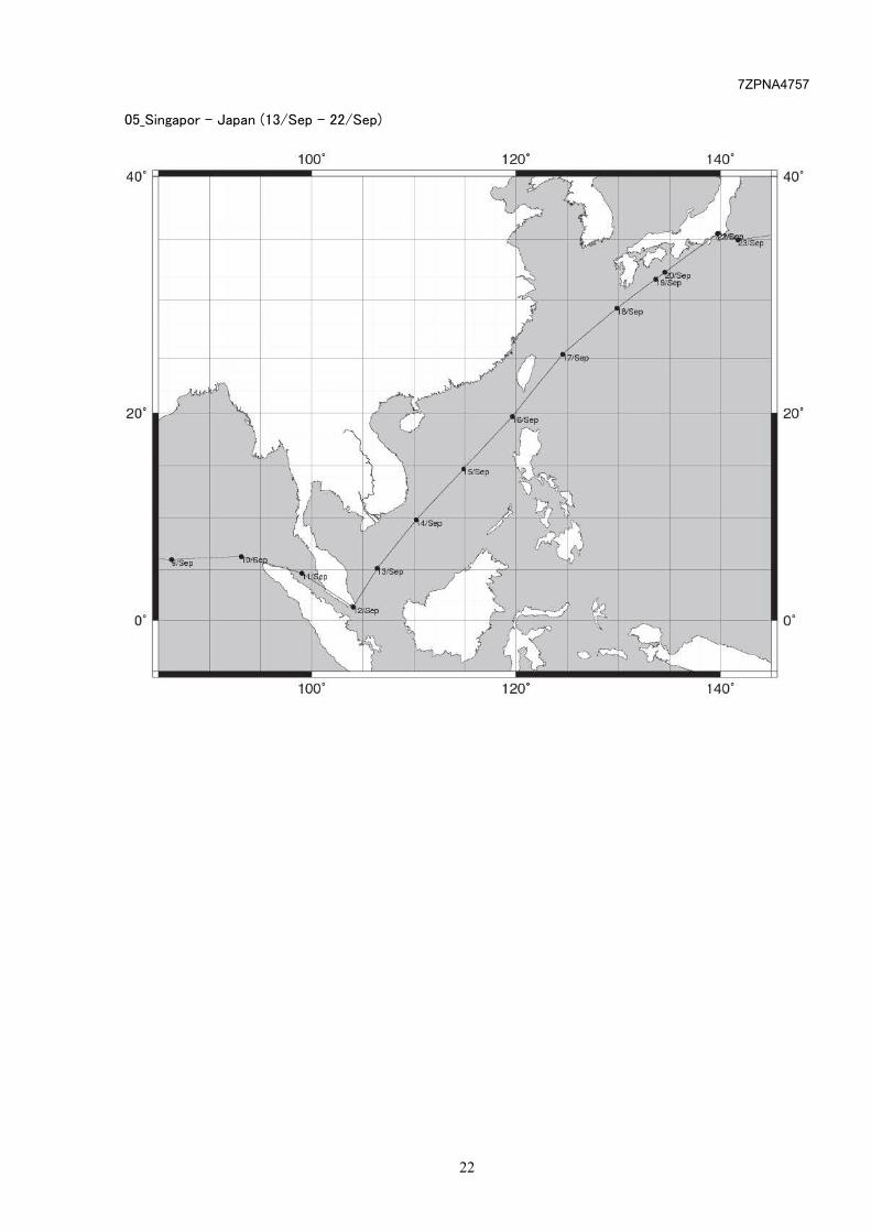
05_Singapor - Japan (13/Sep - 22/Sep)

7ZPNA4757
23
06_Japan - USA (23/Sep - 4/Oct)
140' 160' 180'
lY 'i(l I ""
40'
v+ ) "-- y
~ i
:::::=:-=
~J. "'21 Sep
-.. '""P -<6/Sep
4JSep -<S!Sep
40'
~ -,,,sep
-
-
20' 20'
140' 160' 180'

7ZPNA4757
24
06_Japan - USA (23/Sep - 4/Oct)
-160' -140' -120'
40'
I ~~~ ~ I F
~ ~ I
~ -r---
I "'0/Sep
~
\ 40'
...
\ ....
20' \, 20'
-160' -140' -120'

7ZPNA4757
25
07_USA - Japan (5/Oct - 25/Oct)
-160' -140° -120°
40' 40°
+ 20' 20°
..
-160' -140" -120"
7ZPNA4757
26
07_USA - Japan (5/Oct - 25/Oct)
140' 160' 180'
~ ~~~~
40'
v t;~ ___..,-6/0ct er5ioct 4/0ct '1·31 1"1
~ ~
~~ £/ ~ / I 40'
KJ-.._,v ,.
-
-
20' + 20'
140' 160' 180'
7ZPNA4757
27
135. 136. 137" 138. 139. 140. 141. 142. 143. 144. 145.
40. 40.
39. l 39.
38. 38.
3T l 3T
36.
35.
34.
33. 33. 135. 136. 137" 138. 139. 140. 141. 142. 143. 144. 145.

NZS-35(ECDIS Training Kit)取扱説明書
Windows 7 / 10 用

7ZPNA4757
目次
1 システム概要 ......................................................................................................................................... 1
2 システム構成 ......................................................................................................................................... 1 2.1 シミュレーション方式 ............................................................................................................................ 1
3 ECDISソフトウェア .................................................................................................................................. 2 3.1 ソフトウェア起動 ................................................................................................................................. 2 3.2 ソフトウェア終了 ................................................................................................................................. 3
4 シミュレータソフトウェア ............................................................................................................................ 5 4.1 ソフトウェア起動 ................................................................................................................................. 5 4.2 ソフトウェア終了 ................................................................................................................................. 6 4.3 画面構成 ......................................................................................................................................... 7 4.4 出力データ設定(GPSタブ) ................................................................................................................. 8 4.5 出力データ設定(GYROタブ) ............................................................................................................ 10 4.6 出力データ設定(SONARタブ) .......................................................................................................... 11 4.7 出力データ設定(DEPTHタブ) ........................................................................................................... 12 4.8 出力データ設定(AUTO PILOTタブ) ..................................................................................................... 13 4.9 出力データ設定(FILEタブ) ............................................................................................................... 14
5 シミュレーションデータ ............................................................................................................................ 16 5.1 AISデータ ........................................................................................................................................ 16
5.1.1 AIS1フォルダ ................................................................................................................................ 16 5.1.2 AIS2フォルダ ................................................................................................................................ 16 5.1.3 AIS3フォルダ ................................................................................................................................ 16
5.2 TT1/TT2データ ............................................................................................................................. 16 5.3 NAVTEXデータ ................................................................................................................................ 17
6 付録1:AISシミュレートデータ(AIS3フォルダ) ............................................................................................ 18

7ZPNA4757
1
1 システム概要 ECDIS ソフトウェアをインストールした各装置ではチャートインストール・アップデート作業、航路作成、航行監視な
ど、ECDIS 基本機能操作を行なうことが可能です。
講師用装置から各種センサデータを配信することで、実際の運行状況に近い航路監視、衝突回避作業を、電
子海図動作確認装置で模擬することが可能です。
2 システム構成 本シミュレーションシステムによるトレーニング環境は以下の構成となります。
講師用装置(MASTER PC)にのみシミュレータソフトが入っています。
2.1 シミュレーション方式
シミュレータで作られたセンサデータはネットワークを介して各端末の ECDIS ソフトウェアに配信されます。
シミュレータ ECDIS ソフトウェア
(GPS/Gyro/Log などのセンサデータ)
センサデータ受信
航路作成や他船情報、ユーザマップ機能
など ECDIS 操作が可能です。
7ZPNA4757
2
3 ECDIS ソフトウェア
3.1 ソフトウェア起動
1) PC の電源を入れます。
2) デスクトップのショートカットメニューを実行します。
3) Task Menu が表示されます。[ECDIS]をクリックし、”Route Planning Route Monitoring”画
面が表示されることを確認します。
ご注意
Task Menu で The index data of chart corrupt…という内容の System ダイアログが出た場合、OKボタンを押してください。
“Route Planning Route Monitoring”画面上に The connection of operation unit failed…と記
載された System ダイアログが出た場合、OK ボタンを押してください。
Task Menu
ECDIS

7ZPNA4757
3
3.2 ソフトウェア終了
1) [Menu]-[ ]をクリックします。
2) [Code Input] をクリックします。
3) “9999”と入力し、Enter をクリックします。
4) Task Menu が表示されるので、“Password”をクリックします。
Input “9999”
7ZPNA4757
4
5) “9999”と入力し、Enter をクリックします。
Input “9999”

7ZPNA4757
5
4 シミュレータソフトウェア
4.1 ソフトウェア起動
1) デスクトップのショートカットメニューを実行します。シミュレーションソフトウェアが起動します。

7ZPNA4757
6
4.2 ソフトウェア終了
1) 右上の[×]ボタン、または右下の[Exit]ボタンを押します。
2) EXIT ダイアログが表示されます。[OK]ボタンを押すと、シミュレーションソフトウェアが終了します。

7ZPNA4757
7
4.3 画面構成
A. MONITOR
現在送信している、UTC(時分秒)、ポジション、針路、船速を表示します。
B. Local Datum
以下の測地系が設定することができます。
“W84:WGS84”, “W72:WGS72”, “S85:SGS85”, “P90:PE90”, “999:user defined”
C. SET
SET ボタン。クリックすると出力データをセットします。
詳細は次ページ以降をご参照ください。
D. EXIT
終了ボタン。クリックするとシミュレータを終了します。
A
B
C
D

7ZPNA4757
8
4.4 出力データ設定(GPS タブ)
(1) LAT, LON(緯度経度設定)
北緯南緯(N/S), 東経西経(E/W)を選択し、緯度経度を入力してください。
SET ボタンをクリックすると送信値が変更されます。
(2) SPEED(船速設定)
船速を入力してください。
SET ボタンをクリックすると送信値が変更されます。
(3) ROT
※本 ECDIS ソフトウェアでは使用しません。
(1)
(2)
(3)
(4)
(6)
(5)

7ZPNA4757
9
(4) $GPGGA GPS Quality indicate(GGA センテンスの GPS 精度の種類選択)
GGA センテンスの Quality indicator 値を選択してください。
0:fix not available or invalid
1:GPS,SPS mode, fix valid (GPS)
2:differential GPS,SPS mode, fix valid (DGPS)
3: GPS, SPS mode fix valid
4: real time kinematics. Satellite system used in RTK mode with fixed integers
5: float RTK.satellite system used in RTK node with floating integers
6: estimated(dead reckoning) mode
7: manual input mode
8: simulator mode
(5) $GPGLL Status(GPS 測位有効/無効フラグの選択)
GLL センテンスの測位有効/無効フラグ値を選択してください
A:data valid(有効)
V: data invalid(無効)
(6) Course
True 真対地方位とヘディングに対するオフセット(-180 度~+180 度)を設定してください。
Magnetic 磁気対地方位とヘディングに対するオフセット(-180 度~+180 度)を設定してください。

7ZPNA4757
10
4.5 出力データ設定(GYRO タブ)
(1) BEARING(針路設定)
針路を入力してください。
SET ボタンをクリックすると送信値が変更されます。
(2) BEARING+(針路の回転設定)
1 秒周期で回頭させる角度を入力してください。
SET ボタンをクリックすると送信値が変更されます。
(3) Mode Indicator
THS センテンスの Mode Indicator を選択してください。
A: Autonomous
E: Estimated (dead reckoning)
M: Manual input
S: Simulator mode
V: Data not valid (including standby)
(1)
(2)
(3)

7ZPNA4757
11
4.6 出力データ設定(SONAR タブ)
(1) $VBVBW Water(VBW センテンス対水速度設定)
VBW センテンスの対水船速値(前後(Longitudinal)、左右(Transverse))を入力してください。
SET ボタンをクリックすると送信値が変更されます。
(2) VBW センテンスの対水船速のステータス
VBW センテンスの対水船速ステータスを選択してください
A: Data valid(有効)
V: Data invalid(無効)
(3) $VBVBW Ground(VBW センテンス対地速度設定)
VBW センテンスの対地船速値(前後(Longitudinal)、左右(Transverse))を入力してください。
SET ボタンをクリックすると送信値が変更されます。
(4) VBW センテンスの対地船速のステータス
VBW センテンスの対地船速ステータスを選択してください
A: Data valid(有効)
V: Data invalid(無効)
(5) SET, DRIFT(潮流設定 VDR センテンス)
Set、Drift の値を入力してください。
SET ボタンをクリックすると送信値が変更されます。
(1) (2)
(3) (4)
(5)

7ZPNA4757
12
4.7 出力データ設定(DEPTH タブ)
(1) Transducer(水深設定。DPT、DBT、DBS センテンス)
Transducer に対する水深を入力してください。
SET ボタンをクリックすると送信値が変更されます。
(2) Surface(オフセット。DPT、DBS センテンス)
オフセット値を入力してください。
SET ボタンをクリックすると送信値が変更されます。
(3) Ships Floor(Depth below keel DBK センテンス)
船底からの水深(Depth below keel)を入力してください。
SET ボタンをクリックすると送信値が変更されます。
(1)
(2)
(3)

7ZPNA4757
13
4.8 出力データ設定(Auto Pilot タブ)
(1) AP Mode
Autopilot のステアリングモードを選択してください。
(1)

7ZPNA4757
14
4.9 出力データ設定(FILE タブ)
(1) Route
航路ファイルを読込み、読み込んだ航路に沿った GPS データを送信します。
送信手順
・①のファイル選択ボタンを押し、ファイル選択画面にて航路ファイルを選択します。②に選択したファイル名が表示さ
れます。
・③にチェックをつけると送信されます。
③
(1)
② ①
(2)
(3)
(4)

7ZPNA4757
15
(2) AIS / TT1 / TT2
log ファイルを読込み、AIS, TT1, TT2 データを送信します。
送信手順
・①のファイル選択ボタンを押し、ファイル選択画面にて log ファイル(AIS, TT1, TT2 の log ファイルから各項目に合った
ファイル)を選択します。②に選択したファイル名が表示されます。
・③に送信周期を入力します。
log ファイルに 10 行データがあった場合は 100ms×10 = 1 秒となります。
・④にチェックをつけると送信されます。
(3) NAVTEX
log ファイルを読込み、NAVTEX データを 1 回送信します。(NMEA の log ファイルのみ対応しています。)
送信手順
・①のファイル選択ボタンを押し、ファイル選択画面にて NAVTEX の log ファイルを選択します。②に選択したファイル
名が表示されます。
・③の SEND ボタンを押すと送信されます。
(4) NAVTEX (Binary)
①
②
②
②
③
③
③ ④
① ②
③
7ZPNA4757
16
5 シミュレーションデータ 4.9 出力データ設定(FILE タブ)で使用できるシミュレータのサンプル log ファイルは下記に入っています。
C:\SimData\
5.1 AIS データ
5.1.1 AIS1 フォルダ
AIS1 フォルダには下記シミュレートデータが保存されています。
ファイル名 備考
AIS_Cyprous.log キプロス
AIS_Nagoya.log 名古屋
AIS_Seatle.log シアトル
AIS_Singapore.log シンガポール
AIS_Tokyo.log 東京
5.1.2 AIS2 フォルダ
AIS2 フォルダには東京湾付近の数日間に渡るシミュレートデータが保存されています。
ファイル形式:SioLogYYYYMMDD-hhmm.log (例) SioLog20070920-0234.log
5.1.3 AIS3 フォルダ
AIS3 フォルダには長期航行のシミュレートデータが、区間ごとに下記フォルダに保存されています。
ファイル形式:SioLogYYYYMMDD-hhmmss.log (例) SioLog20100815-003421.log
各ファイル名につけられた日付と地図上の概略位置は巻末の資料をご参照ください。
フォルダ名
01_Singapor-India
02_India-Suez
03_Suez-India
04_India-Singapor
05_Singapor-Japan
06_Japan-USA
07_USA-Japan
5.2 TT1/TT2 データ
ARPA フォルダ以下に、TT1.log、TT2.log の 2 つのシミュレーションデータが保存されています。

7ZPNA4757
17
これらのデータは自船の周囲に円弧状にレーダターゲットを配置します。
5.3 NAVTEX データ
NAVTEX フォルダ以下に、NAVTEX_NMEA.log というファイル名のシミュレーションデータが保存されています。
下記に示すデータがシミュレートされます。受信した ECDIS はチャート上に MSI マークを表示します。
※本 ECDIS ソフトウェアは NMEA フォーマットにのみ対応しております。JRC フォーマットには対応しておりません。
PA74
NAVTEX TEST DATA No.1
NETHERLANDS COASTGUARD
NAVIGATIONAL WARNING NR74 211600UTCJAN
PLATFORM L13-FD-1 53-15.5N004-14.5E
UNLIT
AC16
NAVTEX TEST DATA No.2
35-06N,139-20E
KW67
NAVTEX TEST DATA No.3
19-06.800N, 156-28.387W
TK36
NAVTEX TEST DATA No.4
39-21.507N,125-54.743W
JA52
NAVTEX TEST DATA No.5
42-36.662S, 129-26.826E
PC85
NAVTEX TEST DATA No.6
34-29N,135-05E
UV16
NAVTEX TEST DATA No.7
33-21N,135-05W
NE71
NAVTEX TEST DATA No.8
75-10.331N, 173-31.928W
75-10.510N,173-32.012W
GD62
NAVTEX TEST DATA No.9
67-53.706S, 76-24.655E
YG08
NAVTEX TEST DATA No.10
15-18.280N,82-23.620E
PA74
NAVTEX TEST DATA No.11
33-16N,132-15E
AC16
NAVTEX TEST DATA No.12
31-03N,130-03E
KW67
NAVTEX TEST DATA No.13
57-45.494N,84-28.627W
57-45.502N, 84-28.965W
57-45.400N, 84-29.000W
TK36
NAVTEX TEST DATA No.14
25-58N,127-52W
JA52
NAVTEX TEST DATA No.15
0-50.532S,18-45.973E
NNNN

7ZPNA4757
18
6 付録 1:AIS シミュレートデータ(AIS3 フォルダ) 01_Sigapor - India (15/Aug - 21/Aug)
80' 100' 40' !=!==::::::;::==jlllll-... --.--.--~===;===+l 40'
20' 20'
+
+
97~t~mub'l7rA•
o· t- + o·
80' 100'

7ZPNA4757
19
02_India - Suez (22/Aug - 31/Aug)
40. 60. so·

7ZPNA4757
20
03_Suez - India (1/Sep - 8/Sep)
40. 60.

7ZPNA4757
21
04_India - Singapor (9/Sep - 12/Sep)
40· ~====~==~80~·--~~--------~--~~==T===~ 1 oo·
40'
t +
20°
80' 1oo·
7ZPNA4757
22
05_Singapor - Japan (13/Sep - 22/Sep)

7ZPNA4757
23
06_Japan - USA (23/Sep - 4/Oct)
140' 160' 180'
~ ~~ ~~
40'
v+ {:; ~ ~
f ~~
~J. Sep
-.., '""P -<6/Sep '"
I 4JSep <S!Sep
40'
~ -<,tSep l
-
-
20' 20'
140' 160' 180'

7ZPNA4757
24
06_Japan - USA (23/Sep - 4/Oct)
-160' -140° -120°
40' ~ISep 40°
20' 20°
+
+
-160' -140° -120'

7ZPNA4757
25
07_USA - Japan (5/Oct - 25/Oct)
-160' -140° -120°
40' + 40°
+ +
_j_
20' 20°
+ +
-160' -140° - 120'

7ZPNA4757
26
07_USA - Japan (5/Oct - 25/Oct)
140' 160' 180'
~ ~~ ~~
40'
v t; ~ ___..,-6/0ct er5ioct 4/0ct '1·31 1"1
~ ~
v~~/ ~ v..ttr
40'
·-
-
20' + 20'
140' 160' 180'

7ZPNA4757
27
135. 136. 137" 138. 139. 140. 141. 142. 143. 144. 145.
40. 40.
39. 39.
38. 38.
3T l 3T
36. 36.
35.
34.
33. 33. 135. 136. 137" 138. 139. 140. 141. 142. 143. 144. 145.