Embed Size (px)
Citation preview

ECB50ECB50-E
ECB50-FGIS
ECB50ECB50-E
ECB50-FGIS
Circuit Breaker Finder and AC Line Tracer
User Manual• Mode d'emploi• Bedienungshandbuch• Manuale d'Uso• Manual de uso
U.S. Service CenterMeterman Test Tools1420 75th Street SWEverett, WA 98203Tel: 888-993-5853Fax: 425-446-6390
Canadian Service CenterMeterman Test Tools400 Britannia Rd. E. Unit #1Mississauga, ON L4Z 1X9Tel: 905-890-7600Fax: 905-89-6866
European Correspondence Address*Meterman Test Tools EuropeP.O. Box 11865602 BD EindhovenThe Netherlands*Correspondence only - no repair or replacement available from this address. European customers please contact your distributor.
Visit www.metermantesttools.com for• Catalog• Application notes• Product specifications• Product manuals
PN 2099447January 2004© Wavetek Meterman Test Tools. All rights reserved. Printed in China. Please Recycle
®
®
®
®

1
ECB50, ECB50-E, and ECB50-FGIS Circuit Breaker Finder and AC Cable Tracer
Contents
Safety Information.............................................................................3Symbols Used in this Manual .........................................................3
Introduction.......................................................................................4Finding Circuit Breakers and Fuses See Figure -1- ..................4Locating and Tracing Cables in Walls See Figure -2-...............5Sorting Out a Single Wire in a Bundle of Cables See Figure -3- ..5
Product Maintenance.........................................................................6Cleaning ..........................................................................................6Replacing the Battery See Figure -4- ................................6
Specifications ....................................................................................6Transmitter .....................................................................................6Receiver ..........................................................................................7
Limited Warranty and Limitation of Liability......................................7Repair ................................................................................................8
Engl
ish

2
6
5
1
2
3
4
ECB50 Receiver
A SensorB On / Pulse LEDC Low Battery IndicatorD Fuse- Line mode switchE On/Off-and sensitivity
adjustment switchF Code Display. “H” indicates
signal received.
2
1ECB50
ECB50FGIS
ECB50E
ECB50 Transmitter
A HandgripB Plug connector

3
Safety InformationTo avoid possible electric shock or personal injury, follow theseguidelines:• Do not use the transmitter/receiver if it is damaged. Before you use
the transmitter/receiver, inspect the case. Look for cracks or missingplastic. Pay particular attention to the insulation surrounding theconnectors.
• If this product is used in a manner not specified by the manufacturer,the protection provided by the equipment may be impaired.
• Do not use the transmitter/receiver if it operates abnormally.Protection may be impaired. When in doubt, have thetransmitter/receiver serviced.
• Do not attempt to repair this transmitter/receiver. There are no userserviceable parts.
• Use caution when working above 30 V ac rms, 42 V peak, or 60 V dc.Such voltages pose a shock hazard.
• Do not operate the transmitter/receiver with the battery door removedor loosened.
• CAT III equipment is designed to protect against transients inequipment in fixed-equipment installations, such as distributionpanels, feeders and short branch circuits, and lighting systems inlarge buildings.
Symbols Used in this ManualSymbols on the instrument and in the instruction manual:W Warns of potential
danger. Refer to themanual
X Dangerous Voltage
T Double insulated.Continuous double orreinforced insulationcomplies to IEC 536,Class II
P Symbol of conformity,confirms conformity withrelevant EU directives. Theinstrument complies with theEMC Directive (89/ 336/ EEC)specifically standardsEN50081-1 and EN50082-1,as well as the Low VoltageDirective (73/23/EEC)described in the standardEN61010-1.

4
IntroductionThe ECB50 Circuit Breaker Finder and AC Cable Locator consists of atransmitter and a receiver housed in a protective denier case. Similar toradio signals, the transmitter functions by means of a coded carriersending a signal into the cable. Using the built-in sensor, the receivercan indicate the transmitted code as a symbol on the display as well asproviding an audible signal. The audible sound level automaticallyintensifies as the source is approached.The ECB50 is the ideal tracing instrument for sorting out AC wires in abundle of cables, tracing lines in overhead installations and walls, andassigning current circuits to fuses.Using the ECB50 you can:• Sort out a single wire in a bundle of cables.• Trace and find AC cable in walls.• Assign current circuits to fuses within fuse panels.• Switch between locating cable lines or locating fuses.• Adjust sensitivity when tracing lines and locating cables.Finding Circuit Breakers and Fuses See Figure -1-1. Turn on the ECB50 receiver using the On/Off switch.2. Set the Fuse/Line switch to the Fuse position.3. Plug the ECB50 transmitter into the voltage socket connected to the
fuse or circuit breaker.4. Turn the On/Off switch toward the top of the receiver to set sensitivity
to the highest sensitivity level. Turn toward the bottom of the receiverto reduce sensitivity.
5. Position the receiver at a 90 degree angle (perpendicular) over thetop of the fuse of circuit breaker. Adjust the sensitivity level until the“H” code is displayed along with a blinking LED and an audible tone.
6. If a reception signal is received at several fuses, use the On/Offswitch to reduce the sensitivity until the minimum reception isreceived. Repeat this procedure until only one fuse indicates areception signal. This fuse protects the socket to which thetransmitter has been connected. The tracing depth amounts toapproximately 10 cm (4 in).

5
WCautionKeep hands clear of wiring when tracing wires or fuses indistribution panels.
Locating and Tracing Cables in Walls See Figure -2-1. Turn on the receiver using the On/Off switch.2. Set the Fuse/Line switch to the Line position.3. Plug the ECB transmitter into the socket for AC line to be traced.4. Turn the On/Off switch toward the top of the receiver to set sensitivity
to the highest sensitivity level. Turn toward the bottom of the receiverto reduce sensitivity.
5. Place the ECB50 receiver close to the transmitter to receive aconfirmation signal that both ECB50 test components are active andworking. The receiver is receiving a signal from the transmitter whenit displays the letter “H” on the display and the LED is blinking. Alsoan audible signal is present with varied loudness depending onstrength of signal received.
6. Next, begin locating the signal in the cable to be traced by circlingaround the socket. When you receive a signal, reduce the sensitivityuntil the minimum signal is received. If the signal decreases, thereceiver is either moving off the AC cable path or the cable is installeddeeper into the wall. If necessary, adjust the sensitivity level toincrease the signal strength. Depending on local conditions, thetracing depth amounts to approx. 0 to 40 cm (0 to 15 inches).
Sorting Out a Single Wire in a Bundleof Cables See Figure -3-1. Turn on the receiver using the On/Off switch.2. Set the Fuse/Line switch to the Line position.3. Plug the ECB transmitter into the socket of the AC wire to be traced.4. Turn the On/Off switch toward the top of the receiver to set sensitivity
to the highest sensitivity level. Turn toward the bottom of the receiverto reduce sensitivity.
5. Place the ECB50 receiver close to the transmitter to receive aconfirmation signal that both ECB50 test components are active andworking. The receiver is receiving a signal from the transmitter whenit displays the letter “H” on the display and the LED is blinking. Alsoan audible signal is present with varied loudness depending onstrength of signal received.
6. Next, try to locate the transmitted signal at the bundle of cables.When you receive a signal, reduce the sensitivity until the minimumreception of the signal is heard and seen. If necessary, increase thesensitivity somewhat to confirm the signal.

6
Product MaintenanceAs long as the instructions in this manual are followed, no specialmaintenance is required.CleaningDisconnect the instrument from all circuits. To clean thetransmitter/receiver, use a soft cloth moistened with water. To avoiddamage to the plastic components do not use benzene, alcohol, acetone,ether, paint thinner, lacquer thinner, ketone or other solvents to clean thetransmitter/receiver. Allow a recovery time of 6 hours after cleaningbefore operating the instrument.Replacing the Battery See Figure -4-A red LED indicates that the battery needs to be replaced. To replace thebattery:1. Turn off the instrument using the On/Off switch2. Loosen the screw on the back of the instrument and open the case.3. Remove the battery and insert the new 9 V alkaline battery using the
correct polarity. Recycle your discharged battery.4. Reassemble the case.5. Insert the screw and tighten it.
SpecificationsHumidity: Valid for 23 °C ± 5°, for less than 80% relative humidity)TransmitterVoltage range: 100 V to 125 V ECB50100 V to 250 V for ECB50-E and ECB50-FGISPower consumption: approximately 1 WFrequency range: 30 to 70 Hz ECB5050 to 60 Hz for ECB50-E and ECB50-FGISTransmission frequency: approximately 8 kHzTransmitter frequency: approximately 10 HzTemperature range: -10 °C to 40 °C at maximum 80% relative humidityDimensions: 70 x 55 x 86 mm (2.8 x 2.1 x 3.4 in)Weight: approximately 65 g (2.3 oz)Overvoltage category: CAT III 150 V ECB 50, CAT III 300 V ECB50-E andECB50-FGISPollution degree: 2Protection class: IP20

7
ReceiverTracing depth for fuse identification: approximately 0 to 10 cm(4 in) depending on local conditionsTracing depth for cable location: approximately 0 to 40 cm (15 in)depending on local conditions.Sensitivity setting: Using On/Off control potentiometerLow battery indication: 7.5 VSwitching fuse/cable: manually using Fuse-Line switchTemperature range: -10 °C to 40 °C (14 ° to 104 °F) at maximum 80%relative humidityDimensions: 22 x 162 x 34 mm ( 0.9 x 6.4 x 1.3 in)Weight: approximately 100 g (3.5 oz)Overvoltage category: CAT III 150 V ECB 50, CAT III 300 V ECB50-E andECB50-FGISPollution degree: 2Protection class: IP20Power supply: 9 V battery, IEC 6LR61, Alkaline onlyApplicable directives and standards:EMC: EN 50081-1, EN 50082-1 ECB50EN 50082-2 ECB50-E and ECB50-FGISLow Voltage Directive: EN 61010-1 ECB50-E and ECB50-FGIS
Limited Warranty and Limitation of LiabilityYour Meterman product will be free from defects in material andworkmanship for 1 year from the date of purchase. This warranty doesnot cover fuses, disposable batteries or damage from accident, neglect,misuse, alteration, contamination, or abnormal conditions of operationor handling. Resellers are not authorized to extend any other warranty onFluke’s behalf. To obtain service during the warranty period, return theproduct with proof of purchase to an authorized Meterman Test ToolsService Center or to a Meterman dealer or distributor. See Repair Sectionfollowing for details. THIS WARRANTY IS YOUR ONLY REMEDY. ALLOTHER WARRANTIES - WHETHER EXPRESS, IMPLIED OR STAUTORY -INCLUDING IMPLIED WARRANTIES OF FITNESS FOR A PARTICULARPURPOSE OR MERCHANTABILITY, ARE HEREBY DISCLAIMED.MANUFACTURER SHALL NOT BE LIABLE FOR ANY SPECIAL, INDIRECT,INCIDENTAL OR CONSEQUENTIAL DAMAGES OR LOSSES, ARISINGFROM ANY CAUSE OR THEORY. Since some states or countries do notallow the exclusion or limitation of an implied warranty or of incidental orconsequential damages, this limitation of liability may not apply to you.

8
RepairAll test tools returned for warranty or non-warranty repair or forcalibration should be accompanied by the following: your name,company’s name, address, telephone number, and proof of purchase.Additionally, please include a brief description of the problem or theservice requested. Non-warranty repair or replacement charges shouldbe remitted in the form of a check, a money order, credit card withexpiration date, or a purchase order made payable to Meterman TestTools.In-Warranty Repairs and Replacement – All CountriesPlease read the warranty statement that follows, and check your batterybefore requesting repair. During the warranty period any defective testtool can be returned to your Meterman Test Tools distributor for anexchange for the same or like product. Please check the “Where to Buy”section on www.metermantesttools.com for a list of distributors nearyou. Additionally, in the United States and Canada In-Warranty repair andreplacement units can also be sent to a Meterman Test Tools ServiceCenter (see below for address).Non-Warranty Repairs and Replacement – US and CanadaNon-warranty repairs in the United States and Canada should be sent toa Meterman Test Tools Service Center. Call Meterman Test Tools orinquire at your point of purchase for current repair and replacementrates.
In USA In CanadaMeterman Test Tools Meterman Test Tools1420 75th Street SW 400 Britannia Rd. E. Unit #1Everett, WA 98203 Mississauga, ON L4Z 1X9Tel: 888-993-5853 Tel: 905-890-7600Fax: 425-446-6390 Fax: 905-890-6866
Non-Warranty Repairs and Replacement – EuropeEuropean non-warranty units can be replaced by your Meterman TestTools distributor for a nominal charge. Please check the “Where to Buy”section on www.metermantesttools.com for a list of distributors nearyou.
European Correspondence Address*Meterman Test Tools EuropeP.O. Box 11865602 BD EindhovenThe Netherlands
*(Correspondence only – no repair or replacement available from thisaddress. European customers please contact your distributor)

9
Cable and Fuse Finder
TRANSMITTER
Cat-No. 4000CAT III 300V
max.250V / 50...60Hz
1
2

10
3
49V6LR61

1
Détecteurs de câbles secteur et de disjoncteurs ECB50,ECB50-E et ECB50-FGIS
Table des matières
Consignes de sécurité .......................................................................3Symboles utilisés dans ce mode d’emploi ......................................3
Introduction.......................................................................................4Localisation des disjoncteurs et des fusibles Voir figure -1-. ..4Localisation et dépistage des câbles dans les parois Voir figure -2-. .5Identification d’un fil dans un faisceau de câbles............................5Voir figure -3-. ................................................................................5
Entretien du produit...........................................................................6Nettoyage........................................................................................6Remplacement de la pile Voir figure -4-. ...............................6
Caractéristiques.................................................................................6Emetteur .........................................................................................6Récepteur........................................................................................7
Limites de garantie et de responsabilité ............................................7Réparation .........................................................................................8
Fran
çais

2
6
5
1
2
3
3
Récepteur ECB50
A DétecteurB Témoin Marche / ImpulsionC Indicateur de pile faibleD Commutateur de mode
fusible-secteurE Bouton de réglage de
sensibilité et marche/arrêtF Affichage des codes. « H »
indique un signal reçu.
2
1ECB50
ECB50FGIS
ECB50E
A PoignéeB Connecteur

3
Consignes de sécuritéPour éviter tout risque d’électrocution ou de blessure corporelle, respecter lesconsignes suivantes :• Ne pas utiliser l’émetteur/récepteur s’il est endommagé. Avant d’utiliser
l’émetteur/récepteur, inspecter son boîtier. Rechercher les éventuelles fissuresou les parties de plastique manquantes.Faire particulièrement attention à l’isolantentourant les connecteurs.
• Ne pas utiliser l’émetteur/récepteur s’il ne fonctionne pas normalement. Saprotection est peut-être défectueuse. En cas de doute, faire réviserl’émetteur/récepteur.
• Ne pas tenter de réparer cet émetteur/récepteur. Il ne contient pas de piècespouvant être remplacées par l’utilisateur.
• Ne pas tenter de réparer cet émetteur/récepteur. Il ne contient pas de piècespouvant être remplacées par l’utilisateur.
• Procéder avec prudence en travaillant avec des tensions supérieures à 30 V c.a.efficace, 42 V maximum ou 60 V c.c. Ces tensions présentent un risqued’électrocution.
• Ne pas utiliser l’émetteur/récepteur avec le couvercle de batterie démonté ou desserré.• Les appareils CAT III sont conçus pour protéger contre les tensions transitoires
dans les installations d’équipements fixes, notamment sur les panneaux dedistribution électrique, les lignes d’alimentation et les circuits dérivés courts ainsique les installations d’éclairage dans les grands bâtiments.
Symboles utilisés dans ce mode d’emploiSymboles sur l’instrument et dans le mode d’emploi :W Signale un danger
potentiel. Se reporterau mode d’emploi
X Tension dangereuse
T Double isolation.Isolation renforcée oudouble continueconforme à CEI 536,classe II
P Ce symbole confirme laconformité aux directives EUpertinentes. L’appareil estconforme à la directive CEM(89/ 336/CEE) aux normesspécifiques EN50081-1 etEN50082-1, et à la directivesur les basses tensions(73/23/CEE) décrite dans lanorme EN61010-1.

4
IntroductionL’identificateur de disjoncteur ECB50 et de câble secteur est constitué d’unémetteur et d’un récepteur logés dans un boîtier protecteur textile. L’émetteurs’apparente aux signaux radioélectriques en utilisant une porteuse codée pourenvoyer un signal dans le câble. Un capteur intégré permet au récepteurd’indiquer le code transmis sous forme de symbole sur l’affichage et deproduire un signal sonore. Le niveau du signal sonore s’intensifieautomatiquement à mesure que la source se rapproche.L’ECB50 est un appareil de dépistage idéal pour identifier les fils à courantalternatif dans un faisceau de câbles, localiser les lignes dans les installationsaériennes et dans les parois, et affecter les circuits électriques aux fusibles.L’utilisation du ECB50 permet de :• distinguer un fil dans un faisceau de câbles ;• localiser et identifier un câble c.a. dans les parois ;• affecter les circuits électriques aux fusibles dans les panneaux de
fusibles ;• basculer entre la localisation des lignes câblées et des fusibles ;• ajuster la sensibilité pendant la localisation des lignes et
l’identification des câbles.Localisation des disjoncteurs et des fusibles Voir figure -1-.1. Mettez le récepteur ECB50 sous tension en utilisant le bouton On/Off.2. Réglez le commutateur Fuse/Line sur la position réservée au fusible.3. Branchez l’émetteur ECB50 dans la prise de tension reliée au fusible
ou au disjoncteur.4. Tournez le bouton On/Off vers le haut du récepteur pour régler le plus
haut niveau de sensibilité possible. Tournez le bouton vers le bas durécepteur pour réduire la sensibilité.
5. Positionnez le récepteur à 90 degrés (perpendiculaire) au fusible dudisjoncteur. Ajustez le niveau de sensibilité jusqu’à l’apparition ducode « H », d’un voyant clignotant et d’une tonalité sonore.
6. Si un signal de réception est reçu au niveau de plusieurs fusibles, utilisez lebouton On/Off pour réduire la sensibilité de façon à obtenir une réceptionminimale. Répétez cette procédure pour n’obtenir un signal de réception qued’un seul fusible. Ce fusible protège les prises dans lesquelles l’émetteur aété branché. La profondeur du dépistage est d’environ 10 cm.

5
WAttentionÉloigner les mains du câblage pendant le dépistage desfils ou des fusibles dans les panneaux électriques.
Localisation et dépistage des câbles dans les parois Voir figure -2-.1. Mettez le récepteur sous tension en utilisant le bouton On/Off.2. Réglez le commutateur Fuse/Line sur la position Line.3. Branchez l’émetteur ECB dans la prise de la ligne secteur à localiser.4. Tournez le bouton On/Off vers le haut du récepteur pour régler le plus haut
niveau de sensibilité possible. Tournez le bouton vers le bas du récepteurpour réduire la sensibilité.
5. Placez le récepteur ECB50 à proximité de l’émetteur pour recevoir un signalconfirmant que les deux composants ECB50 sont actifs et fonctionnels pourle test. Le récepteur reçoit un signal de l’émetteur à l’apparition de la lettre« H » sur l’affichage et du voyant clignotant. Un signal sonore retentitégalement avec une intensité variable selon la force du signal reçu.
6. Lancez ensuite la recherche du signal dans le câble concerné en décrivantdes cercles autour de la prise. Une fois le signal reçu, réduisez la sensibilitéjusqu’à l’obtention d’un signal minimum. Si le signal diminue, cela signifieque le récepteur s’éloigne du câble secteur ou que le câble se trouve plusprofondément dans la paroi. Ajustez le niveau de sensibilité s’il y a lieu pouraugmenter la puissance du signal. Selon les conditions locales, laprofondeur de dépistage se situe entre 0 et 40 cm (0 à 15 pouces).
Identification d’un fil dans un faisceau de câblesVoir figure -3-.
1. Mettez le récepteur sous tension en utilisant le bouton On/Off.2. Réglez le commutateur Fuse/Line sur la position Line.3. Branchez l’émetteur ECB dans la prise de la ligne secteur à localiser.4. Tournez le bouton On/Off vers le haut du récepteur pour régler le plus
haut niveau de sensibilité possible. Tournez le bouton vers le bas durécepteur pour réduire la sensibilité.
5. Placez le récepteur ECB50 à proximité de l’émetteur pour recevoir un signalconfirmant que les deux composants ECB50 sont actifs et fonctionnels pourle test. Le récepteur reçoit un signal de l’émetteur à l’apparition de la lettre« H » sur l’affichage et du voyant clignotant. Un signal sonore retentitégalement avec une intensité variable selon la force du signal reçu.
6. Essayez ensuite de localiser le signal transmis au niveau du faisceau decâbles. Une fois le signal reçu, réduisez la sensibilité jusqu’à la confirmationvisuelle et sonore de la réception d’un signal minimum. Augmentez lasensibilité s’il y a lieu pour confirmer le signal.

6
Entretien du produitAucune maintenance particulière n’est exigée dans la mesure où lesconsignes de ce manuel sont respectées.NettoyageDébranchez l’instrument de tous les circuits. Nettoyer l’émetteur/récepteur àl’aide d’un chiffon doux imbibé d’eau. Afin de ne pas endommager lescomposants en plastique, ne pas utiliser de benzène, d’alcool, d’acétone,d’éther, de diluant pour peinture ou peinture-laque, de cétone ou d’autressolvants pour nettoyer l’émetteur/récepteur. Prévoyez un délai de 6 heuresaprès le nettoyage avant de recommencer à utiliser l’appareil.Remplacement de la pile Voir figure -4-.Un voyant rouge indique que la pile doit être remplacée. Pour laremplacer :1. Mettez l’appareil hors tension en utilisant le bouton On/Off.2. Desserrez la vis au dos de l’appareil et ouvrez le boîtier.3. Retirez la pile et insérez la nouvelle pile alcaline de 9 V en utilisant la
polarité correcte. Recyclez la pile usagée.4. Remontez le boîtier.5. Insérez la vis et serrez-la.
CaractéristiquesHumidité : Valable à 23°C ± 5°, avec moins de 80 % d’humidité relative)EmetteurGamme de tension : 100 V à 125 V ECB50100 V à 250 V pour ECB50-E et ECB50-FGISConsommation d’énergie : environ 1 WGamme de fréquence : 30 à 70 Hz ECB5050 à 60 Hz pour ECB50-E et ECB50-FGISFréquence d’émission : environ 8 kHzFréquence d’émetteur : environ 10 HzPlage de température : de -10 °C à 40 °C avec 80 % d’humidité relativemaximumDimensions : 70 x 55 x 86 mm (2,8 x 2,1 x 3,4 pouces)Poids : environ 65 g (2,3 oz)Catégorie de surtension : CAT III 150 V ECB 50, CAT III 300 V ECB50-Eet ECB50-FGISDegré de pollution : 2Classe de protection : IP20

7
RécepteurProfondeur de dépistage pour l’identification des fusibles : de 0 à 10 cm(4 pouces) environ en fonction des conditions localesProfondeur de dépistage pour l’identification des câbles : de 0 à 40 cm(14 pouces) environ en fonction des conditions locales.Réglage de sensibilité : à l’aide du potentiomètre de réglage marche/arrêt(OFF)Témoin de pile faible : 7,5 VCommutation fusible/câble : utilisation manuelle du commutateur Fuse-LinePlage de température : de -10 °C à 40 °C (14 ° à 104 °F) avec 80 %d’humidité relative maximumDimensions : 22 x 162 x 34 mm (0,9 x 6,4 x 1,3 pouces)Poids : environ 100 g (99,22 g)Catégorie de surtension : CAT III 150 V ECB 50, CAT III 300 V ECB50-Eet ECB50-FGISDegré de pollution : 2Classe de protection : IP20Alimentation : Pile de 9 V, CEI 6LR61, alcaline uniquementNormes et directives applicables : CEM : EN 50081-1, EN 50082-1 ECB50EN 50082-2 ECB50-E et ECB50-FGISDirective sur les basses tensions : EN 61010-1 ECB50-E et ECB50-FGIS
Limites de garantie et de responsabilitéMeterman garantit l’absence de vices de matériaux et de fabrication de ce produit dans desconditions normales d’utilisation et d’entretien pendant une période d’un an prenant effet à ladate d’achat. Cette garantie ne s’applique pas aux fusibles, aux piles jetables ni à tout produitmal utilisé, modifié, contaminé, négligé ou endommagé par accident ou soumis à desconditions anormales d’utilisation et de manipulation. Les distributeurs agréés par Fluke nesont pas autorisés à appliquer une garantie plus étendue au nom de Fluke. Pour bénéficier de lagarantie, renvoyez le produit accompagné d’un justificatif d’achat auprès d’un centre deservices agréé par Meterman Test ou du distributeur ou du revendeur Meterman. Voir lasection Réparation suivante pour tous les détails. LA PRESENTE GARANTIE EST LE SEUL ETEXCLUSIF RECOURS. TOUTES AUTRES GARANTIES, EXPLICITES, IMPLICITES OUSTATUTAIRES, NOTAMMENT LES GARANTIES DE QUALITE MARCHANDE OUD’ADAPTATION A UN OBJECTIF PARTICULIER SONT EXCLUES PAR LES PRESENTES. LEFABRICANT NE SERA EN AUCUN CAS TENU RESPONSABLE DE DOMMAGESPARTICULIERS, INDIRECTS, ACCIDENTELS OU CONSECUTIFS, NI D’AUCUNS DEGATS OUPERTES DE DONNEES, SUR UNE BASE CONTRACTUELLE, EXTRA-CONTRACTUELLE OUAUTRE. Etant donné que certains pays ou états n’admettent pas les limitations d’une conditionde garantie implicite, ou l’exclusion ou la limitation de dégâts accidentels ou consécutifs, leslimitations et les exclusions de cette garantie ne s’appliquent pas obligatoirement àchaque acheteur.

8
RéparationTous les outils de test renvoyés pour un étalonnage ou une réparation couverte ou non par lagarantie doivent être accompagnés des éléments suivants : nom, raison sociale, adresse,numéro de téléphone et justificatif d’achat. Veuillez inclure également une brève description duproblème ou du service demandé. Les frais de remplacement ou de réparation hors garantiedoivent être acquittés par chèque, mandat, carte de crédit avec date d’expiration, ou par bon decommande payable à l’ordre de Meterman Test Tools.Remplacements et réparations sous garantie – Tous paysVeuillez lire la déclaration de garantie qui suit, et vérifiez la pile avant de demander uneréparation. Pendant la période de garantie, tout outil de test défectueux peut être renvoyéauprès de votre distributeur Meterman Test Tools pour être échangé contre un produitidentique ou similaire. Consultez la section « Where to Buy » sur le sitewww.metermantesttools.com pour obtenir la liste des distributeurs dans votre région. AuCanada et aux Etats-Unis, les appareils devant être remplacé ou réparé sous garantie peuventégalement être envoyés dans un centre de services (voir les adresses ci-dessous).Remplacements et réparations hors garantie – Canada et Etats-UnisLes appareils à réparer hors garantie au Canada et aux Etats-Unis doivent êtreenvoyés dans un centre de services Meterman Test Tools. Appelez Meterman TestTools ou renseignez-vous auprès de votre lieu d’achat pour connaître les tarifs envigueur de remplacement ou de réparation.
Aux Etats-Unis Au CanadaMeterman Test Tools Meterman Test Tools1420 75th Street SW 400 Britannia Rd. E. Unit #1Everett, WA 98203 Mississauga, Ontario L4Z 1X9Tél. : 888-993-5853 Tél. : 905-890-7600Fax : 425-446-6390 Fax : 905-890-6866
Remplacements et réparations hors garantie – EuropeLes appareils européens non couverts par la garantie peuvent être remplacés parvotre distributeur Meterman Test Tools pour une somme nominale. Consultez lasection « Where to Buy » sur le site www.metermantesttools.com pour obtenir laliste des distributeurs dans votre région.
Adresse postale européenne*Meterman Test Tools EuropeP.O. Box 11865602 B.D. EindhovenPays-Bas
*(Réservée à la correspondance – Aucune réparation ou remplacement n’est possibleà cette adresse. Nos clients européens doivent contacter leur distributeur.)

1
ECB50, ECB50-E und ECB50-FGIS zum Auffinden vonTrennschaltern und Wechselstromkabeln
Inhalt
Sicherheitsinformationen ............................................................... 3Symbole in diesem Handbuch ..................................................... 3
Einleitung........................................................................................ 4Auffinden von Trennschaltern und Sicherungen Siehe Abbildung -1- ..................................................................... 4Auffinden und Verfolgen von Kabeln in Wänden Siehe Abbildung -2-... 5Aussortieren eines Kabels in einem Bündel von Kabeln Siehe Abbildung -3- 5
Produktwartung.............................................................................. 6Reinigung..................................................................................... 6Ersetzen der Batterie Siehe Abbildung -4-.................... 6
Technische Daten ........................................................................... 6Sender.......................................................................................... 6Empfänger ................................................................................... 7
Beschränkte Gewährleistung und Haftungsbeschränkung ............. 7Reparatur........................................................................................ 8
Deut
sch
2
6
5
1
2
3
3
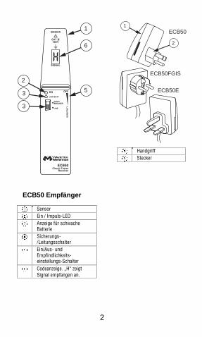
ECB50 Empfänger
A SensorB Ein / Impuls-LEDC Anzeige für schwache
BatterieD Sicherungs-
/LeitungsschalterE Ein/Aus- und
Empfindlichkeits-einstellungs-Schalter
F Codeanzeige. „H“ zeigtSignal empfangen an.
2
1ECB50
ECB50FGIS
ECB50E
A HandgriffB Stecker

3
SicherheitsinformationenZur Vermeidung von Stromschlag oder Verletzungen folgende Richtlinieneinhalten:• Den Sender/Empfänger nicht verwenden, wenn er beschädigt ist. Vor dem
Gebrauch des Senders/Empfängers das Gehäuse untersuchen. Nach Rissenoder herausgebrochenem Kunststoff suchen. Die Isolierung im Bereich derAnschlüsse besonders sorgfältig untersuchen.
• Wenn dieses Produkt in einer hier nicht beschriebenen Art verwendetwird, wird der durch das Gerät gebotene Schutz unter Umständenbeeinträchtigt.
• Den Sender/Empfänger nicht verwenden, wenn das GerätFunktionsstörungen aufweist. Unter Umständen sind dieSicherheitsvorkehrungen beeinträchtigt. Im Zweifelsfall denSender/Empfänger von einer Servicestelle prüfen lassen.
• Nicht versuchen diesen Sender/Empfänger zu reparieren. Es gibtkeine kundenseitig wartbaren Teile.
• Bei Arbeiten mit mehr als 30 V Wechselspannung eff., 42 V Spitzeoder 60 V Gleichspannung Vorsicht walten lassen. SolcheSpannungen bergen Stromschlaggefahr.
• Den Sender/Empfänger nicht betreiben, wenn dieBatteriefachabdeckung entfernt oder lose ist.
• Die CAT III-Ausrüstung ist so konzipiert, dass sie gegenimpulsförmige Störsignale in fest installierten Geräten wie z. B.Verteilertafeln, Zuleitungen und kurze Verzweigungsstromkreise undBeleuchtungssystemen in großen Gebäuden schützt.
Symbole in diesem HandbuchSymbole am Instrument und im Bedienungshandbuch:W Weist auf potenzielle
Gefahren hin. ImHandbuch nachlesen.
X Gefährliche Spannung
T Schutzisoliert.UnunterbrocheneSchutzisolierung undverstärkte Isolierung inÜbereinstimmung mitIEC 536, Klasse II
P Symbol bestätigt Konformitätmit relevanten EU-Richtlinien.Das Instrument stimmtüberein mit: EMC-Richtlinie(89/ 336/ EEC), insbesondereEN50081-1 und EN50082-1und auchNiederspannungsrichtlinie(73/23/EEC), beschrieben inEN61010-1.
4
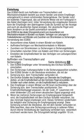
EinleitungDas ECB50-Gerät zum Auffinden von Trennschaltern undWechselstromkabeln besteht aus einem Sender und einem Empfänger,untergebracht in einem schützenden Deniergehäuse. Der Sender nutztein kodiertes Trägersignal, das auf ähnliche Weise wie ein Funksignal indas Kabel übertragen wird. Unter Verwendung des eingebauten Sensorskann der Empfänger den übertragenen Code als Symbol auf der Anzeigeund auch als akustisches Signal anzeigen. Der akustische Pegel wirdbeim Annähern an die Quelle automatisch verstärkt.Das ECB50 ist das ideale Ortungsinstrument zum Aussortieren vonWechselstromkabeln in Bündeln von Kabeln, Verfolgen von Leitungen inFreikabelstrecken und Wänden und Zuordnen von Stromkreisen zu Sicherungen.Verwendung des ECB50:• Aussortieren eines Kabels in einem Bündel von Kabeln.• Auffinden/Verfolgen von Wechselstromkabeln in Wänden.• Zuordnen von Stromkreisen zu Sicherungen in Sicherungsfeldern.• Umschalten zwischen Orten von Kabeln und Orten von Sicherungen.• Einstellen der Empfindlichkeit für das Verfolgen von Leitungen/Orten
von Kabeln.Auffinden von Trennschaltern undSicherungen Siehe Abbildung -1-1. Den ECB50 Empfänger unter Verwendung des Ein/Aus-Schalters
einschalten.2. Den Sicherungs-/Leitungsschalter in die Sicherungsposition schalten.3. Den ECB50 Sender in die Steckdose einstecken, die mit der
Sicherung bzw. dem Trennschalter verbunden ist.4. Den Ein/Aus-Schalter des Empfängers zur Oberseite des Empfängers
drehen, um die Empfindlichkeit auf den höchsten Pegel einzustellen. DenSchalter nach unten drehen, um die Empfindlichkeit zu reduzieren.
5. Den Empfänger in einem Winkel von 90 Grad (rechtwinklig) über derSicherung bzw. dem Trennschalter positionieren. DenEmpfindlichkeitspegel anpassen, bis der Code „H“ zusammen miteiner blinkenden LED und einem akustischen Signal angezeigt wird.
6. Wenn bei mehreren Sicherungen ein Empfangssignal festgestelltwird, die Empfindlichkeit mit dem Ein/Aus-Schalter reduzieren, bisdas minimale Signal empfangen wird. Dieses Verfahren wiederholenbis lediglich eine Sicherung ein Empfangssignal anzeigt. DieseSicherung schützt die Steckdose, die mit dem Sender verbunden ist.Bitte beachten, dass eine Sicherungszuordnung in seltenen Fällendurch interne Verdrahtung der Spannung verhindert bzw. wesentlicherschwert werden kann. Die Ortungstiefe beträgt ungefähr 10 cm.

5
WVorsichtBeim Orten/Verfolgen von Drähten oder Sicherungen inVerteilfeldern die Hände in sicherem Abstand zu den Drähtenhalten.
Auffinden und Verfolgen von Kabeln in Wänden Siehe Abbildung -2-1. Den Empfänger unter Verwendung des Ein/Aus-Schalters einschalten.2. Den Sicherungs-/Leitungsschalter in die Leitungsposition schalten.3. Den ECB Sender in die Steckdose des zu verfolgenden
Wechselstrom-Stromkreises stecken.4. Den Ein/Aus-Schalter zur Oberseite des Empfängers drehen, um die
Empfindlichkeit auf den höchsten Pegel einzustellen. Den Schalter desEmpfängers nach unten drehen, um die Empfindlichkeit zu reduzieren.
5. Den ECB50 Empfänger nahe zum Sender führen, um ein Signal zuempfangen, das bestätigt, dass beide ECB50 Testkomponenten aktiviert sindund funktionieren. Der Empfänger empfängt ein Signal des Senders, wenndie Anzeige des Empfängers den Buchstaben „H“ anzeigt und die LED blinkt.Darüber hinaus wird ein akustisches Signal ausgegeben, dessen Lautstärkevon der Stärke des empfangenen Signals abhängt.
6. Durch Einkreisen in der Umgebung der Steckdose mit der Ortung desSignals im zu verfolgenden Kabel beginnen. Wenn ein Signal empfangenwird, die Empfindlichkeit reduzieren, bis das minimale Signal empfangenwird. Wenn das Signal schwächer wird, wird entweder der Empfänger vonder Wechselstromkabelstrecke weggeführt oder das Kabel ist tiefer in derWand installiert. Falls erforderlich, den Empfindlichkeitspegel anpassen, umdie Signalstärke zu erhöhen. Abhängig von den jeweiligen Bedingungen vorOrt beträgt die Ortungstiefe ungefähr 0 bis 40 cm.
Aussortieren eines Kabels in einem Bündel von Kabeln Siehe Abbildung -3-1. Den Empfänger unter Verwendung des Ein/Aus-Schalters einschalten.2. Den Sicherungs-/Leitungsschalter in die Leitungsposition schalten.3. Den ECB Sender in die Steckdose des zu verfolgenden
Wechselstrom-Stromkreises stecken.4. Den Ein/Aus-Schalter zur Oberseite des Empfängers drehen, um die
Empfindlichkeit auf den höchsten Pegel einzustellen. Den Schalter desEmpfängers nach unten drehen, um die Empfindlichkeit zu reduzieren.
5. Den ECB50 Empfänger nahe zum Sender führen, um ein Signal zuempfangen, das bestätigt, dass beide ECB50 Testkomponenten aktiviert sindund funktionieren. Der Empfänger empfängt ein Signal des Senders, wenndie Anzeige des Empfängers den Buchstaben „H“ anzeigt und die LED blinkt.Darüber wird ein akustischen Signal ausgegeben, dessen Lautstärke von derStärke des empfangenen Signals abhängt.
6. Dann versuchen, das übertragene Signal im Bündel von Kabeln zu orten.Wenn ein Signal empfangen wird, die Empfindlichkeit reduzieren, bis das

6
minimale Signal optisch und akustisch angezeigt wird. Falls erforderlich, denEmpfindlichkeitspegel leicht erhöhen, um das Signal zu bestätigen.
ProduktwartungSolange die Anleitungen in diesem Handbuch befolgt werden, ist keinebesondere Wartung erforderlich.ReinigungDas Instrument von allen Stromkreisen trennen. Den Sender/Empfänger mit einemweichen, mit Wasser angefeuchteten Lappen reinigen. Um eine Beschädigung derPlastikteile zu vermeiden, niemals Benzin, Alkohol, Azeton, Äther, Farb- oderLackverdünner, Keton oder andere Lösungsmittel zur Reinigung desSenders/Empfängers verwenden. Nach einer Reinigung 6 Stunden Erholungszeitgewähren, bevor das Instrument wieder eingesetzt wird.Ersetzen der Batterie Siehe Abbildung -4-Eine rote LED zeigt an, dass die Batterie ersetzt werden muss. Ersetzender Batterie:1. Das Instrument unter Verwendung des Ein/Aus-Schalters ausschalten.2. Die Schraube an der Rückseite des Instruments lösen und das
Gehäuse öffnen.3. Die Batterie entfernen und eine neue alkalische 9-V-Batterie unter Beachtung
der korrekten Polarität einsetzen. Die verbrauchte Batterie recyceln.4. Das Gehäuse wieder zusammenbauen.5. Die Schraube einsetzen und anziehen.
Technische DatenFeuchtigkeit: Gültig für 23°C ± 5° (für weniger als 80 % relative Feuchtigkeit)SenderSpannungsbereich:100 V bis 125 V für ECB50100 V bis 250 V für ECB50-E und ECB50-FGISStromverbrauch: ungefähr 1 WFrequenzbereich: 30 bis 70 Hz für ECB5050 bis 60 Hz für ECB50-E und ECB50-FGISÜbertragungsfrequenz: ungefähr 8 kHzSendefrequenz: ungefähr 10 HzTemperaturbereich: -10 °C bis 40 °C bei maximal 80 % relativer FeuchtigkeitAbmessungen: 70 x 55 x 86 mmGewicht: ungefähr 65 gÜberspannungskategorie: CAT III 150 V ECB50, CAT III 300 V ECB50-E und ECB50-FGISVerschmutzungsgrad: 2Schutzklasse: IP20

7
EmpfängerOrtungstiefe für Sicherungserkennung: ungefähr 0 bis 10 cmabhängig von örtlichen BedingungenOrtungstiefe für Kabelerkennung: ungefähr 0 bis 40 cm, abhängig von örtlichenBedingungen.Empfindlichkeitseinstellung: Verwendung Ein/Aus-SteuerpotentiometerAnzeige für schwache Batterie: 7,5 VUmschalten Sicherung/Kabel: manuell mit Sicherungs-/LeitungsschalterTemperaturbereich: -10 °C bis 40 °C (14 ° bis 104 °F) bei maximal 80 % relativerFeuchtigkeitAbmessungen: 22 x 162 x 34 mmGewicht: ungefähr 100 gÜberspannungskategorie: CAT III 150 V ECB50, CAT III 300 V ECB50-E und ECB50-FGISVerschmutzungsgrad 2Schutzklasse: IP20Stromversorgung: 9-V-Batterie, IEC 6LR61, nur alkalischGeltende Richtlinien und Normen:EN 50081-1, EN 50082-1 ECB50EN 50082-2 ECB50-E und ECB50-FGISNiederspannungsrichtlinie: EN 61010-1 ECB50-E und ECB50-FGIS
Beschränkte Gewährleistung und HaftungsbeschränkungEs wird gewährleistet, dass dieses Meterman-Produkt für die Dauer von einemJahr ab dem Kaufdatum frei von Material- und Fertigungsdefekten ist.DieseGewährleistung erstreckt sich nicht auf Sicherungen, Einwegbatterien oderSchäden durch Unfälle, Nachlässigkeit, Missbrauch, Änderungen oderabnormale Betriebsbedingungen bzw. unsachgemäße Handhabung.DieVerkaufsstellen sind nicht dazu berechtigt, diese Gewährleistung im Namen vonFluke zu erweitern. Um während der Gewährleistungsperiode Serviceleistungenzu beanspruchen, das Produkt mit Kaufnachweis an ein autorisiertes MetermanTest Tools Service-Center oder an einen Meterman-Fachhändler/-Distributoreinsenden. Einzelheiten siehe Abschnitt „Reparatur“. DIESE GEWÄHRLEISTUNGSTELLT DEN EINZIGEN UND ALLEINIGEN RECHTSANSPRUCH AUFSCHADENERSATZ DAR.- ALLE ANDEREN GEWÄHRLEISTUNGEN -VERTRAGLICH GEREGELTE ODER GESETZLICHE VORGESCHRIEBENE -EINSCHLIESSLICH DER GESETZLICHEN GEWÄHRLEISTUNG DERMARKTFÄHIGKEIT UND DER EIGNUNG FÜR EINEN BESTIMMTEN ZWECK,WERDEN ABGELEHNT. DER HERSTELLER ÜBERNIMMT KEINE HAFTUNGFÜR SPEZIELLE, INDIREKTE, NEBEN- ODER FOLGESCHÄDEN ODERVERLUSTE, DIE AUF BELIEBIGER URSACHE ODER RECHTSTHEORIEBERUHEN. Weil einige Staaten oder Länder den Ausschluss oder dieEinschränkung einer implizierten Gewährleistung sowie von Begleit- oderFolgeschäden nicht zulassen, ist diese Gewährleistungsbeschränkungmöglicherweise für Sie nicht gültig.

8
ReparaturZu allen Geräten, die zur Reparatur oder Kalibrierung im Rahmen der Garantieoder außerhalb der Garantie eingesendet werden, muss folgendes beigelegtwerden: Name des Kunden, Firmenname, Adresse, Telefonnummer undKaufbeleg. Zusätzlich bitte eine kurze Beschreibung des Problems oder dergewünschten Serviceleistung beilegen. Die Gebühren für Reparaturen außerhalbder Garantie oder für den Ersatz von Instrumenten müssen als Scheck,Geldanweisung, Kreditkarte (Kreditkartennummer mit Ablaufdatum) beglichenwerden oder es muss ein Auftrag an Meterman Test Tools formuliert werden.Bitte die nachfolgende Garantieerklärung lesen und die Batterie prüfen, bevorReparaturen angefordert werden. Während der Garantieperiode können alledefekten Geräte zum Umtausch gegen dasselbe oder ein ähnliches Produkt anden Meterman Test Tools-Distributor gesendet werden. Ein Verzeichnis derzuständigen Distributoren ist im Abschnitt „Where to Buy“ (Verkaufsstellen) aufder Website www.metermantesttools.com zu finden. Darüber hinaus können inden USA und in Kanada Geräte an ein Meterman Test Tools Service-Center(Adresse siehe weiter unten) zur Reparatur oder zum Umtauscheingesendet werden.Reparaturen und Austausch außerhalb der Garantie – USA und KanadaFür Reparaturen außerhalb der Garantie in den Vereinigten Staaten und inKanada werden die Geräte an ein Meterman Test Tools Service-Center gesendet.Auskunft über die derzeit geltenden Reparatur- und Austauschgebührenerhalten Sie von Meterman Test Tools oder der Verkaufsstelle.
In den USA: In Kanada:Meterman Test Tools Meterman Test Tools1420 75th Street SW 400 Britannia Rd. E. Unit #1Everett, WA 98203 Mississauga, ON L4Z 1X9Tel: 888-993-5853 Tel: 905-890-7600Fax: 425-446-6390 Fax: 905-890-6866
Reparaturen und Austausch außerhalb der Garantie – EuropaGeräte außerhalb der Garantie können durch den zuständigen Meterman TestTools-Distributor gegen eine Gebühr ersetzt werden. Ein Verzeichnis derzuständigen Distributoren ist im Abschnitt „Where to Buy“ (Verkaufsstellen) aufder Website www.metermantesttools.com zu finden.
Korrespondenzanschrift für Europa*Meterman Test Tools EuropeP.O. Box 11865602 BD EindhovenNiederlande
*(Nur Korrespondenz – keine Reparaturen, kein Umtausch unterdieser Anschrift. Kunden in Europa wenden sich an denzuständigen Distributor.)
1
Rivelatore di interruttori automatici e di cavi elettrici in c.a.ECB50, ECB50-E e ECB50-FGIS
Indice
Informazioni sulla sicurezza ..............................................................3Simboli adoperati nel presente manuale .........................................3
Introduzione ......................................................................................4Rilevamento di interruttori automatici e fusibili Vedi Figura -1- .... 4Individuazione di cavi nelle pareti Vedi Figura -2- .... 5Individuazione di un singolo cavo in un intero cablaggioVedi Figura -3- ................................................................................5
Manutenzione del prodotto................................................................6Pulizia .............................................................................................6Sostituzione della pila Vedi Figura -4- .... 6
Dati tecnici.........................................................................................6Trasmettitore ..................................................................................6Ricevitore........................................................................................7
Garanzia limitata e limitazione di responsabilità ................................7Riparazioni.........................................................................................8
Italia
no

2
6
5
1
2
3
3
Ricevitore ECB50
A SensoreB Spia ON/PULSE
(Acceso/impulsi)C Spia Low Bat (Pila scarica)D Selettore di modalità Fuse
(Fusibile)/Line (Linea)E Interruttore di
accensione/spegnimento eregolatore di sensibilità
F Display dei codici. “H”indica la ricezione delsegnale.
2
1ECB50
ECB50FGIS
ECB50E
A ImpugnaturaB Spina

3
Informazioni sulla sicurezzaPer prevenire possibili scosse elettriche e altre cause di infortunio,prendere le seguenti precauzioni.• Non usare il trasmettitore e/o il ricevitore se sembrano danneggiati.
Prima di usare il trasmettitore e/o il ricevitore, ispezionarnel’involucro. Verificare che non vi siano incrinature e che nonmanchino parti di plastica. Esaminare attentamente le condizionidell’isolamento attorno ai connettori.
• Usare lo strumento solo secondo queste istruzioni, o si rischia dicomprometterne la protezione interna.
• Non usare il trasmettitore e/o il ricevitore se funzionano in modoanomalo. I dispositivi interni di protezione potrebbero esseredanneggiati. In caso di dubbi, far controllare il trasmettitore e/o ilricevitore presso un centro di assistenza.
• Non tentare di riparare il trasmettitore e/o il ricevitore, in quanto noncontengono parti riparabili dall’utente.
• Esercitare cautela quando si lavora con corrente alternata maggiore di30 V c.a. (valore efficace), 42 V (picco) o 60 V c.c. Tali livelli ditensione possono causare scosse elettriche.
• Non azionare il trasmettitore e/o il ricevitore con lo sportello dellabatteria rimosso o allentato.
• Gli apparecchi CAT III sono realizzati per la protezione dai transitori inimpianti fissi, quali ad esempio quadri di distribuzione, alimentatori,cortocircuiti derivati e impianti di illuminazione di grandi edifici.
Simboli adoperati nel presente manualeI seguenti sono i simboli usati sullo strumento e nel manuale di istruzioni.W Avvertenza di possibile
pericolo. Consultare ilmanuale.
X Alta tensione
T Isolamento doppio.L’isolamento doppiocontinuo o rinforzato èconforme alla normaIEC 536, Classe II.
P Simbolo di conformità.Conferma la conformità alledirettive UE pertinenti. Lostrumento è conforme allaDirettiva 89/336/CEE sullacompatibilità elettromagnetica, ein particolare alle normeEN50081-1 e EN50082-1; èinoltre conforme alla Direttiva73/23/CEE sulle basse tensioni,descritta nella norma EN61010-1.

4
IntroduzioneIl rivelatore di interruttori automatici e cavi elettrici in c.a. ECB50 sicompone di un trasmettitore e di un ricevitore alloggiato in una custodiaprotettiva di tessuto. Il trasmettitore opera per mezzo di una portantecodificata che invia un segnale nel cavo, simile ai segnali radio. Grazie alsensore incorporato, il ricevitore indica sul display il codice trasmesso,in forma di simbolo, ed emette un segnale acustico. Il volume dellasegnalazione aumenta in funzione della prossimità al generatore.l’ECB50 è lo strumento ideale per individuare cavi in c.a. in un cablaggio,seguire linee elettriche in impianti aerei e pareti, e abbinare circuiti dicorrente ai relativi fusibili.Con l’ECB50 è possibile:• individuare un singolo cavo in un intero cablaggio;• rilevare e seguire cavi elettrici in c.a. nelle pareti;• abbinare circuiti di corrente ai relativi fusibili in un quadro;• passare dall’individuazione di cavi al rilevamento di fusibili;• regolare la sensibilità durante le operazioni di rilevamento.Rilevamento di interruttori automatici e fusibili Vedi Figura -1-1. Accendere il ricevitore ECB50 agendo sull’apposito interruttore.2. Portare il selettore Fuse/Line sulla posizione Fuse.3. Collegare il trasmettitore ECB50 alla presa in tensione collegata al
fusibile o all’interruttore automatico.4. Spostare verso l’alto l’interruttore di accensione/spegnimento per
regolare la sensibilità al livello massimo. Per ridurla, spostare ilregolatore verso il basso..
5. Avvicinare il ricevitore al fusibile o all’interruttore automatico,tenendolo a 90°, ossia perpendicolare, sopra di esso. Regolare lasensibilità finché la ricezione non è confermata dalla visualizzazionedel codice “H” sul display, dal lampeggiare della spia e dall’emissionedi un segnale acustico.
6. Se il segnale proviene da più fusibili, ridurre la sensibilità fino allaricezione minima. Ripetere l’operazione fino a ricevere il segnale daun solo fusibile. Questo fusibile protegge la presa a cui è collegato iltrasmettitore. Tenere presente che in rari casi l’assegnazione di unfusibile può avere un’impedenza considerevole a causa della tensionedel cablaggio interno. La profondità di rilevamento è di circa 10 cm.

5
WAttenzioneQuando si seguono fili o fusibili in quadri didistribuzione, tenere le mani a distanza dal cablaggio.
Individuazione di cavi nelle pareti Vedi Figura -2-1. Accendere il ricevitore agendo sull’apposito interruttore.2. Portare il selettore Fuse/Line sulla posizione Line.3. Collegare il trasmettitore ECB50 alla presa della linea in c.a. da seguire.4. Spostare verso l’alto l’interruttore di accensione/spegnimento per
regolare la sensibilità al livello massimo. Per ridurla, spostare ilregolatore verso il basso.
5. Avvicinare il ricevitore ECB50 al trasmettitore per ricevere il segnale diconferma che entrambi i componenti ECB50 sono attivi e funzionanti. Allaricezione del segnale dal trasmettitore, il ricevitore visualizza il codice “H” suldisplay e la spia lampeggia. Inoltre, emette una segnalazione acustica il cuivolume aumenta o diminuisce in funzione della potenza del segnale ricevuto.
6. Muovere lo strumento davanti alla presa, con un movimento circolare, periniziare a individuare il segnale del cavo da seguire. Ricevuto il segnale,ridurre la sensibilità fino percepirlo al livello minimo. Se il segnalediminuisce, significa che il ricevitore si sta allontanando dal percorso delcavo o che il cavo è stato posato in un punto più interno nella parete. Senecessario, regolare la sensibilità per aumentare la potenza del segnale. Laprofondità del cavo da seguire può variare da 0 a 40 cm circa, a secondadelle condizioni specifiche.
Individuazione di un singolo cavo inun intero cablaggio Vedi Figura -3-1. Accendere il ricevitore agendo sull’apposito interruttore.2. Portare il selettore Fuse/Line sulla posizione Line.3. Collegare il trasmettitore ECB50 alla presa a cui è connesso il cavo in
c.a. da seguire.4. Spostare verso l’alto l’interruttore di accensione/spegnimento per
regolare la sensibilità al livello massimo. Per ridurla, spostare ilregolatore verso il basso.
5. Avvicinare il ricevitore ECB50 al trasmettitore per ricevere il segnale diconferma che entrambi i componenti ECB50 sono attivi e funzionanti. Allaricezione del segnale dal trasmettitore, il ricevitore visualizza il codice “H” suldisplay e la spia lampeggia. Inoltre, emette una segnalazione acustica il cuivolume aumenta o diminuisce in funzione della potenza del segnale ricevuto.
6. Tentare di individuare il segnale trasmesso presso il fascio di cavi.Ricevuto il segnale, ridurre la sensibilità fino percepirlo e vederlo allivello minimo. Se necessario, aumentare leggermente la sensibilitàper confermare il segnale.

6
Manutenzione del prodottoNon è necessario alcun intervento particolare di manutenzione, purché siusi lo strumento in conformità alle istruzioni in questo manuale.PuliziaScollegare lo strumento da tutti gli eventuali circuiti. Per pulire lostrumento, adoperare un panno morbido inumidito con acqua. Perevitare danni ai componenti plastici, quando si pulisce il trasmettitore e/oil ricevitore non usare benzene, alcol, acetone, etere, diluenti per verniceo lacca, chetoni o altri solventi. Prima di usare di nuovo lo strumento,lasciare passare 6 ore dopo la pulizia.Sostituzione della pila Vedi Figura -4-L’accensione di una spia LED rossa indica che la pila deve esseresostituita. Per sostituire la pila, procedere come segue.1. Spegnere lo strumento agendo sull’apposito interruttore.2. Allentare la vite sul retro dello strumento e aprire l’involucro.3. Rimuovere la pila e inserirne una nuova, alcalina e da 9 V,
accertandosi che la polarità sia corretta. Riciclare la batteria vecchia.4. Rimontare lo strumento.5. Inserire la vite a serrarla.
Dati tecniciUmidità: dati tecnici a 23 °C ± 5°, con <80% di umidità relativaTrasmettitorePortata di tensione: 100–125 V per il modello ECB50100–250 V per i modelli ECB50-E ed ECB50-FGISPotenza assorbita: circa 1 WPortata di frequenza: 30–70 Hz per il modello ECB5050–60 Hz per i modelli ECB50-E ed ECB50-FGISFrequenza di trasmissione: circa 8 kHzFrequenza del trasmettitore: circa 10 HzIntervallo di temperature: da -10 a 40 °C con un massimo dell’80% diumidità relativaDimensioni: 70 x 55 x 86 mmPeso: circa 65 gCategoria di sovratensione:CAT III 150 V per il modello ECB50, CAT III300 V per i modelli ECB50-E ed ECB50-FGISLivello di inquinamento: 2Protection classe di protezione: IP20

7
RicevitoreProfondità per il rilevamento di fusibili: da 0 a 10 cm circa a seconda dellecondizioni specificheProfondità per il rilevamento di cavi: da 0 a 40 cm circa a seconda dellecondizioni specificheSensibilità: regolata con il potenziometro di accensione/spegnimentoIndicazione di pila scarica: a 7,5 VSelezione delle funzioni fusibile/cavo: manuale, con il selettoreFuse/LineIntervallo di temperature: da -10 a 40 °C con un massimo dell’80% diumidità relativaDimensioni: 22 x 162 x 34 mmPeso: circa 100 gCategoria di sovratensione: CAT III 150 V per il modello ECB50, CAT III300 V per i modelli ECB50-E ed ECB50-FGISLivello di inquinamento: 2Protection classe di protezione: IP20Alimentazione: pila da 9 V, IEC 6LR61, esclusivamente alcalinaConformità a direttive e norme:Compatibilità elettromagnetica: EN 50081-1, EN 50082-1 per il modello ECB50EN 50082-2 per i modelli ECB50-E ed ECB50-FGISDirettive sulle basse tensioni: EN 61010-1 per i modelli ECB50-E ed ECB50-FGIS
Garanzia limitata e limitazione di responsabilitàQuesto prodotto Meterman sarà esente da difetti di materiale e fabbricazione per 1 anno adecorrere dalla data di acquisto. Sono esclusi da questa garanzia i fusibili, le pile monousoe i danni causati da incidenti, negligenza, uso improprio, alterazione, contaminazione ocondizioni anomale di funzionamento o manipolazione. I rivenditori non sono autorizzati aoffrire alcun’altra garanzia a nome della Fluke. Per richiedere un intervento durante ilperiodo di garanzia, restituire il prodotto, allegando la ricevuta di acquisto, a un centro diassistenza autorizzato Meterman Test Tools oppure a un rivenditore o distributoreMeterman locale. Per ulteriori informazioni vedere la sezione Riparazioni. QUESTAGARANZIA È IL SOLO RICORSO A DISPOSIZIONE DELL’ACQUIRENTE, E SOSTITUISCEQUALSIASI ALTRA GARANZIA, ESPRESSA, IMPLICITA O PREVISTA DALLA LEGGE,COMPRESA, MA NON A TITOLO ESCLUSIVO, QUALSIASI GARANZIA IMPLICITA DICOMMERCIABILITÀ O DI IDONEITÀ PER SCOPI PARTICOLARI. IL PRODUTTORE NONSARÀ RESPONSABILE DI DANNI O PERDITE SPECIALI, INDIRETTI O ACCIDENTALI,DERIVANTI DA QUALSIASI CAUSA O TEORIA. Poiché alcuni stati o Paesi non permettonol’esclusione o la limitazione di una garanzia implicita o di danni accidentali o indiretti,questa limitazione di responsabilità potrebbe non applicarsi all’acquirente.

8
RiparazioniA tutti gli strumenti di misura restituiti per interventi in garanzia o noncoperti dalla garanzia, oppure per la taratura, devono essere allegate leseguenti informazioni: il proprio nome e quello dell’azienda, indirizzo,numero telefonico e scontrino. Allegare anche una breve descrizione delproblema o dell’intervento richiesto. Gli importi dovuti per sostituzioni oriparazioni non coperte dalla garanzia vanno versati tramite assegno,vaglia bancario, carta di credito con data di scadenza od ordine diacquisto all’ordine di Meterman Test Tools.Sostituzioni e riparazioni in garanzia – Tutti i PaesiSi prega di leggere la seguente garanzia e di controllare la pila prima dirichiedere una riparazione. Durante il periodo di garanzia, si puòrestituire uno strumento difettoso al rivenditore Meterman Test Tools perricevere un prodotto identico o analogo. Nella sezione “Where to Buy”del sito www.metermantesttools.com c’è un elenco dei distributori piùvicini. Negli Stati Uniti e nel Canada gli strumenti da sostituire o ripararein garanzia possono essere inviati anche a un centro di assistenzaMeterman Test Tools (l’indirizzo è più avanti).Sostituzioni e riparazioni non coperte dalla garanzia – Usa e CanadaPer riparazioni non coperte dalla garanzia, negli Stati Uniti e nel Canadalo strumento deve essere inviato a un centro di assistenza MetermanTest Tools. Rivolgersi alla Meterman Test Tools o al rivenditore perinformazioni sui costi delle riparazioni e sostituzioni.
USA CanadaMeterman Test Tools Meterman Test Tools1420 75th Street SW 400 Britannia Rd. E. Unit #1Everett, WA 98203 Mississauga, ON L4Z 1X9Tel: 888 993 5853 Tel: 905 890 7600Fax: 425 446 6390 Fax: 905 890 6866
Sostituzioni e riparazioni non coperte dalla garanzia – EuropaGli strumenti acquistati in Europa e non coperti dalla garanzia possonoessere sostituiti dal rivenditore Meterman Test Tools per un importonominale. Nella sezione “Where to Buy” del sitowww.metermantesttools.com c’è un elenco dei distributori più vicini.
Recapito postale europeo*Meterman Test Tools EuropeP.O. Box 11865602 BD EindhovenPaesi Bassi
*(Solo per corrispondenza – non rivolgersi a questo indirizzo perriparazioni o sostituzioni. Si pregano i clienti europei di rivolgersial rivenditore.)

1
ECB50, ECB50-E y ECB50-FGIS Buscador de disyuntor y rastreador de cables de CA
Índice
Información sobre seguridad ............................................................3Símbolos utilizados en este manual................................................3
Introducción ......................................................................................4Localización de interruptores de circuito y de fusibles Ver la figura -1-...............................................................................4Localización y rastreo de cables en paredes Ver la figura -2- ..5Localización de un conductor en medio de un haz de cables Ver la figura -3-...............................................................................5
Mantenimiento del instrumento.........................................................6Limpieza..........................................................................................6Reemplazo de la pila Ver la figura -4- .............................6
Especificaciones ................................................................................6Transmisor......................................................................................6Receptor .........................................................................................7
Garantía limitada y Limitación de responsabilidad ............................7Reparación ........................................................................................8
Espa
ñol

2
6
5
1
2
3
3
Receptor ECB50
A SensorB Encendido / Pulse LEDC Indicador de batería bajaD Interruptor de modo
Fusible-LíneaE Interruptor de
Encendido/Apagado y deajuste de sensibilidad
F Exhibición de códigos. “H”indica señal recibida.
2
1ECB50
ECB50FGIS
ECB50E
A EmpuñaduraB Enchufe

3
Información sobre seguridadSiga estas pautas para evitar la posibilidad de descargas eléctricas olesiones personales:• No utilice el transmisor/receptor si está dañado. Antes de utilizar el
transmisor/receptor, inspeccione la caja. Busque rajaduras o partesplásticas faltantes.Preste especial atención al aislamiento en torno delos conectores.
• Si este producto se utiliza de una manera no especificada por elfabricante, podría verse afectada la protección provista por el equipo.
• No utilice el transmisor/receptor si está funcionando mal. Podríaverse afectada la protección. En caso de duda, haga ver eltransmisor/receptor por un profesional de servicio autorizado.
• {>No trate de reparar este transmisor/receptor. No hay piezas quepuedan ser reparadas por el usuario.
• Tenga cuidado cuando trabaje con voltajes superiores a los30 V ca rms, 42 V pico o 60 V cc. Dichos voltajes representanun peligro de descarga eléctrica.
• No opere el transmisor/receptor con la puerta de la batería retirada o floja.• Los equipos que responden a la especificación CAT III están
diseñados para proteger contra transitorios en equipos deinstalaciones de equipo fijo tales como paneles de distribución, losalimentadores y los circuitos de ramificación corta, y los sistemas deiluminación en grandes edificios.
Símbolos utilizados en este manualSímbolos en el instrumento y en el manual de instrucciones:W Advierte sobre la
posibilidad de peligro.Consulte el manual
X Voltaje peligroso
T De aislamiento doble. Elaislamiento doblecontinuo o reforzadocumple con la normaIEC 536, Clase II
P Símbolo de conformidad,confirma la conformidad a laspautas pertinentes de la UE. Elinstrumento cumple con ladirectiva EMC (89/ 336/ EEC)específicamente, las normasEN50081-1 y EN50082-1, asícomo la directiva de Bajo Voltaje(73/23/EEC) descrita en lanorma EN61010-1.

4
IntroducciónEl buscador de interruptor de circuitos y rastreador de cables de CA ECB50consiste de un transmisor y un receptor encerrados en una caja de protecciónde denier. El buscador de interruptor de circuitos y rastreador de cables de CAECB50 consiste de un transmisor y un receptor encerrados en una caja deprotección de denier. Mediante el sensor integrado, el receptor puede indicar elcódigo transmitido como un símbolo en la pantalla, así como emitir una señalaudible. El nivel del sonido audible aumenta automáticamente a medida que elinstrumento se aproxima a la fuente.El ECB50 es el instrumento de rastreo ideal para organizar conductoresde CA en un haz de cables, rastrear líneas en instalaciones aéreas yparedes y asignar circuitos de corriente a fusibles.Utilizando el ECB50 usted puede:• Ubicar un conductor en medio de un haz de cables.• Rastrear y encontrar cables de CA en paredes.• Asignar circuitos de corriente a fusibles en los paneles de fusibles.• Conmutar entre ubicar líneas de cable o localizar fusibles.• Ajustar la sensibilidad al rastrear líneas y ubicar cables.Localización de interruptores de circuito y de fusibles
Ver la figura -1-1. Encienda el receptor ECB50 mediante el interruptor
“On/Off”(Encendido/Apagado).2. Lleve el interruptor Fusible/Línea a la posición de Fusible.3. Enchufe el transmisor ECB50 en el zócalo de voltaje conectado al
fusible o al interruptor de circuitos.4. Para configurar la sensibilidad a su mayor nivel, gire el interruptor de
encendido/apagado hacia la parte superior del receptor. Para reducirla sensibilidad, gírelo hacia la parte inferior del receptor.
5. Coloque el receptor a un ángulo de 90 grados (perpendicular) sobrela parte superior del fusible del interruptor de circuito. Ajuste el nivelde sensibilidad hasta que se exhiba el código “H” junto con un LEDintermitente y un tono audible.
6. Si se recibe una señal de recepción en varios fusibles, utilice el interruptor deencendido/apagado para reducir la sensibilidad hasta que se detecte larecepción mínima. Repita este procedimiento hasta que sólo un fusible indiquela señal de recepción. Este fusible protege el zócalo al cual se ha conectado eltransmisor. La profundidad de rastreo llega a los 10 cm.
WPrecauciónMantenga las manos alejadas del cableado cuando debarastrear cables o fusibles en paneles de distribución.

5
Localización y rastreo de cables en paredes Ver la figura -2-1. Encienda el receptor mediante el interruptor “On/Off”(Encendido/Apagado).2. Lleve el interruptor Fusible/Línea a la posición de Línea.3. Enchufe el transmisor ECB en el zócalo de la línea de CA a ser rastreada.4. Para configurar la sensibilidad a su mayor nivel, gire el interruptor de
encendido/apagado hacia la parte superior del receptor. Para reducir lasensibilidad, gírelo hacia la parte inferior del receptor.
5. Coloque el receptor ECB50 cerca del transmisor para recibir una señal deconfirmación de que ambos componentes de comprobación del ECB50están activos y funcionando. Se puede reconocer que el receptor estárecibiendo una señal del transmisor cuando exhibe la letra “H” en la pantallay el LED está titilando. También habrá presente una señal audible devolumen diverso, según sea la intensidad de la señal recibida.
6. Coloque el receptor ECB50 cerca del transmisor para recibir una señal deconfirmación de que ambos componentes de comprobación del ECB50están activos y funcionando. Se puede reconocer que el receptor estárecibiendo una señal del transmisor cuando exhibe la letra “H” en la pantallay el LED está titilando. También habrá presente una señal audible devolumen diverso, según sea la intensidad de la señal recibida. Dependiendode las condiciones locales, la profundidad de rastreo alcanzaaproximadamente de 0 a 40 cm (0 a 15 pulgadas).
Localización de un conductor en medio de un haz de cablesVer la figura -3-
1. Encienda el receptor mediante el interruptor “On/Off”(Encendido/Apagado).2. Lleve el interruptor Fusible/Línea a la posición de Línea.3. Enchufe el transmisor ECB en el zócalo del conductor de CA a ser rastreado.4. Para configurar la sensibilidad a su mayor nivel, gire el interruptor de
encendido/apagado hacia la parte superior del receptor. Para reducirla sensibilidad, gírelo hacia la parte inferior del receptor.
5. Coloque el receptor ECB50 cerca del transmisor para recibir unaseñal de confirmación de que ambos componentes de comprobacióndel ECB50 están activos y funcionando. Se puede reconocer que elreceptor está recibiendo una señal del transmisor cuando exhibe laletra “H” en la pantalla y el LED está titilando. También habrápresente una señal audible de volumen diverso, según sea laintensidad de la señal recibida.
6. Luego, trate de ubicar la señal de transmisión en el haz de cables. Cuandoreciba una señal, disminuya la sensibilidad hasta que se escuche y se vea lamínima recepción de la señal. Si fuera necesario, aumente un tanto lasensibilidad para confirmar la señal.

6
Mantenimiento del instrumentoNo se requiere de ningún mantenimiento especial, siempre y cuando sesigan las instrucciones contenidas en este manual.LimpiezaDesconecte el instrumento de todos los circuitos. Para limpiar eltransmisor/receptor, utilice un paño suave humedecido en agua. Para evitardaños a los componentes plásticos, no utilice para la limpieza deltransmisor/receptor benceno, alcohol, acetona, éter, diluyente de pinturas,diluyente de lacas, cetona u otros solventes. Antes de utilizar el instrumentoluego de su limpieza, deje transcurrir un período de recuperación de 6 horas.Reemplazo de la pila Ver la figura -4-Un LED rojo indica que debe reemplazarse la pila. Para reemplazar la pila:
1. Apague el instrumento mediante el interruptor“On/Off”(Encendido/Apagado).
2. Afloje el tornillo de la parte posterior del instrumento y abra la caja.3. Retire la pila e instale la nueva pila alcalina de 9 V observando la
polaridad correcta. Recicle su pila descargada.4. Vuelva a cerrar la caja.5. Inserte el tornillo y ajústelo.
EspecificacionesHumedad: Válido para 23°C ± 5°, para una humedad relativa menor de 80%TransmisorRango de voltaje: 100 V a 125 V para ECB50100 V a 250 V para ECB50-E y ECB50-FGISConsumo de energía: aproximadamente 1 WRango de frecuencia: 30 a 70 Hz para ECB5050 a 60 Hz para ECB50-E y ECB50-FGISFrecuencia de transmisión: aproximadamente 8 kHzFrecuencia del transmisor: aproximadamente 10 HzRango de temperatura: -10 ° ºC a 40 °C a una humedad relativamáxima del 80%Dimensions: 70 x 55 x 86 mm (2,8 x 2,1 x 3,4 pulg.)Peso: aproximadamente 65 g (65.20 g)Categoría de sobrevoltaje: CAT III 150 V ECB50, CAT III 300 V ECB50-Ey ECB50-FGISGrado de polución: 2Clase de protección: IP20

7
ReceptorProfundidad de rastreo para la identificación de fusibles:aproximadamente 0 a 10 cm (4 pulg.) dependiendo de las condicioneslocalesProfundidad de rastreo para la localización de cables:aproximadamente 0 a 40 cm (15 pulg.) dependiendo de las condicioneslocales.Ajuste de sensibilidad: Utilizando potenciómetro de control deencendido/apagadoSeñal de pila descargada: 7,5 VConmutación entre fusible y cable: manualmente por medio delinterruptor Fusible-LíneaRango de temperatura: -10 °C a 40 °C (14 ° a 104 °F) al máximo dehumedad relativa del 80%Dimensiones: 22 x 162 x 34 mm (0,9 x 6,4 x 1,3 pulg.)Peso: aproximadamente 100 g (3,5 oz)Categoría de sobrevoltaje: CAT III 150 V ECB50, CAT III 300 V ECB50-Ey ECB50-FGISGrado de polución: 2Clase de protección: IP20Fuente de alimentación: Una pila alcalina únicamente, de 9 V, IEC6LR61Directivas y normas de aplicación: EMC: EN 50081-1, EN 50082-1ECB50 EN 50082-2 ECB50-E y ECB50-FGIS. Directiva de bajo voltaje: EN61010-1 ECB50-E y ECB50-FGIS
Garantía limitada y Limitación de responsabilidadSu producto Meterman estará libre de defectos de material y mano de obra durante 1 año apartir de la fecha de adquisición. Esta garantía no cubre fusibles, baterías descartables o dañosque son consecuencia de accidentes, negligencia, uso indebido, alteración, contaminación ocondiciones anormales de operación o manipulación. Los revendedores no están autorizados aextender ninguna otra garantía en nombre de Fluke. Para obtener servicio durante el período degarantía, regrese el producto con una prueba de compra a un centro de servicio autorizado porMeterman de equipos de comprobación o a un concesionario o distribuidor de Meterman.Consulte la sección Reparación, a continuación, para obtener detalles. ESTA GARANTÍACONSTITUYE SU ÚNICO RESARCIMIENTO. TODAS LAS DEMÁS GARANTÍAS, TANTOEXPRESAS, IMPLÍCITAS O ESTATUTARIAS, INCLUYENDO LAS GARANTÍAS IMPLÍCITAS DEADECUACIÓN PARA UN PROPÓSITO DETERMINADO O COMERCIABILIDAD, QUEDAN PORLA PRESENTE DESCONOCIDAS. EL FABRICANTE NO DEBERÁ SER CONSIDERADORESPONSABLE DE NINGÚN DAÑO O PÉRDIDA TANTO ESPECIALES, INDIRECTOS,CONTINGENTES O RESULTANTES QUE SURJAN DE CUALQUIER CAUSA O TEORÍA. Debidoa que ciertos estados o países no permiten la exclusión o limitación de una garantía implícita ode los daños contingentes o resultantes, esta limitación de responsabilidad puede no regir parausted.

8
ReparaciónTodas las herramientas de comprobación devueltas para su calibración o reparación, cubiertaso no por la garantía, deberán estar acompañadas por lo siguiente: su nombre, el nombre de laempresa, la dirección, el número de teléfono y una prueba de compra. Además, incluya unabreve descripción del problema o del servicio solicitado. Los pagos correspondientes areparaciones o reemplazos no cubiertos por la garantía se deben remitir a la orden deMeterman Test Tools en forma de cheque, giro postal, pago mediante tarjeta de crédito (incluirel número y la fecha de vencimiento) u orden de compra.Reparaciones y reemplazos cubiertos por la garantía – Todos los paísesAntes de solicitar una reparación sírvase leer la siguiente declaración de garantía y compruebeel estado de la pila. Durante el periodo de garantía, toda herramienta de comprobación en malestado de funcionamaiento puede ser devuelta al distribuidor de Meterman Test Tools paracambiarla por otra igual o un producto semejante. Consulte la sección “Dónde comprar” delsitio www.metermantesttools.com en Internet para obtener una lista de los distribuidores de suzona. Además, en los Estados Unidos y Canadá, las unidades para reparación y reemplazocubiertas por la garantía también se pueden enviar a un Centro de Servicio de Meterman TestTools (las direcciones se incluyen más adelante).Reparaciones y reemplazos no cubiertos por la garantía – Estados Unidos y CanadáLas unidades para reparaciones no cubiertas por la garantía en Estados Unidos yCanadá se deben enviar a un Centro de Servicio de Meterman Test Tools. Póngase encontacto con Meterman Test Tools o con el vendedor de su producto para solicitarinformación acerca de los precios vigentes para reparación y reemplazo.
En Estados Unidos En CanadáMeterman Test Tools Meterman Test Tools1420 75th Street SW 400 Britannia Rd. E. Unit #1Everett, WA 98203 Mississauga, ON L4Z 1X9Tel: 888-993-5853 Tel: 905-890-7600Fax: 425-446-6390 Fax: 905-890-6866
Reparaciones y reemplazos no cubiertos por la garantía – EuropaEl distribuidor de Meterman Test Tools puede reemplazar aplicando un cargo nominal lasunidades vendidas en Europa no cubiertas por la garantía. Consulte la sección “Dóndecomprar” del sitio www.metermantesttools.com en Internet para obtener una lista de losdistribuidores de su zona.
Dirección para envío de correspondencia en Europa*Meterman Test Tools EuropeP.O. Box 11865602 BD EindhovenThe Netherlands
*(Correspondencia solamente. En esta dirección no se suministranreparaciones ni reemplazos. Los clientes europeos deben ponerse encontacto con el distribuidor.)

ECB50ECB50-E
ECB50-FGIS
ECB50ECB50-E
ECB50-FGIS
Circuit Breaker Finder and AC Line Tracer
User Manual• Mode d'emploi• Bedienungshandbuch• Manuale d'Uso• Manual de uso
U.S. Service CenterMeterman Test Tools1420 75th Street SWEverett, WA 98203Tel: 888-993-5853Fax: 425-446-6390
Canadian Service CenterMeterman Test Tools400 Britannia Rd. E. Unit #1Mississauga, ON L4Z 1X9Tel: 905-890-7600Fax: 905-89-6866
European Correspondence Address*Meterman Test Tools EuropeP.O. Box 11865602 BD EindhovenThe Netherlands*Correspondence only - no repair or replacement available from this address. European customers please contact your distributor.
Visit www.metermantesttools.com for• Catalog• Application notes• Product specifications• Product manuals
PN 2099447January 2004© Wavetek Meterman Test Tools. All rights reserved. Printed in China. Please Recycle
®
®
®
®


![arXiv:1512.07713v4 [math.ST] 29 Sep 2017 · Let Fbe a distribution with support Xand g: X!Rpbe an F-integrable function such that := E Fgis of interest. If fX tgis an F-invariant](https://img.dokumen.tips/doc/110x75/60675b8741f1e547814bd07f/arxiv151207713v4-mathst-29-sep-2017-let-fbe-a-distribution-with-support-xand.jpg)


