Embed Size (px)
Citation preview

EC6302: DIGITAL ELECTRONICS Department of ECE
1
DHANALAKSHMI SRINIVASAN COLLEGE OF ENGINEERING AND TECHNOLOGY
ECR, MAMALLAPURAM
CHENNAI-603104
DEPARTMENT OF ELECTRONICS AND
COMMUNICATION ENGINEERING
EC6302- DIGITAL ELECTRONICS
QUESTION BANK
PREPARED BY
M.PRIYADARSHINI /AP/ECE

EC6302: DIGITAL ELECTRONICS Department of ECE
2
UNIT-I: MINIMIZATION TECHNIQUES AND LOGIC GATES
PART A - C204.1
1. How many bits are required to represent the decimal numbers in the range 0 to 999 using
straight binary code? Using BCD codes?
(999) 10 = ( 1111100111 ) 2 → 10 bits are required using straight binary code
(999) 10 = ( 1001 1001 1001 ) BCD → 12 bits are required using BCD code
2. Show that the excess-3 code is self-complementing. Self-complementing property: 1’s complement of XS-3 code of a decimal digit is equal to XS-3
code of 9’s complement of the corresponding decimal digit.
Example:
XS-3 code of the decimal digit 2 = 0101
1’s complement of 0101 = 1010 --------------------(1)
9’s complement of 2 = 9-2 = 7
XS-3 code of 7 = 1010 --------------------(2)
The self- complementing property of XS-3 code is proved from equations (1) & (2)
3. What is meant by weighted and non-weighted code?
Weighted codes are those, which obey the positional weighting principles. In weighed code, each
position of the number represents a specific weight. Example: 8421, 2421 & 84-2-1.
Non-Weighted Codes are codes that are not positionally weighted. Each position of the number is
not assigned a fixed value. Example: Excess-3 & Gray code
4. Add the decimals 67 and 78 using excess-3 code.
67 = ( 0110 0111 ) BCD = ( 1001 1010 ) XS-3
78 = ( 0111 1000 ) BCD = ( 1010 1011 ) XS-3
------------------------------
1 0100 0101 ( + )
0011 0011 0011
-------------------------------
( 0100 0111 1000 ) XS-3
-------------------------------
5. Write the two properties of Gray code & mention the application of Gray code.
Properties:
(1) The gray code is non-weighted code, which means that there are no specific weights assigned
to the bit positions.
(2) In gray code, only one bit changes from one number to the next.
Application: Shaft position encoder in which analog data are represented by continuous change of
shaft position. The shaft is partitioned into segments, and each segment is assigned a number.
6. State & prove De-Morgan’s theorem. (May/June 2013, Nov/Dec 2015)
De-Morgan’s theorem 1: The complement of product of any number of variables is equivalent to
sum of the individual complements.
De-Morgan’s theorem 2: The complement of sum of any number of variables is equivalent to
product of the individual complements.
Proof:
a) (AB)’ = A’ + B’ b) (A+B)’ = A’B’
7. Use De Morgan’s theorem to convert the following expressions to one that has only single
variable inversions?
Y = (RS’T+Q’)’
Z = [ (A+BC) (D+EF) ]’
X = [ (A’+C) (B+D’) ]’
Ans: Y = (RS’T+Q’)’ = ( R’+S+T ’) Q
Z = [ (A+BC)(D+EF) ]’ = (A+BC)’+(D+EF)’
Z = A’(BC)’ + D’(EF)’ = A’(B’+C’) + D’(E’+F’) = A’B’+A’C’+D’E’+D’F’
A B AB (AB)’ A’ B’ A’+B’ 0 0 0 1 1 1 1 0 1 0 1 1 0 1 1 0 0 1 0 1 1 1 1 1 0 0 0 0
A B A+B (A+B)’ A’ B’ A’B’ 0 0 0 1 1 1 1 0 1 1 0 1 0 0 1 0 1 0 0 1 0 1 1 1 0 0 0 0

EC6302: DIGITAL ELECTRONICS Department of ECE
3
X = [ (A’+C) (B+D’) ]’ = (A’+C)’ + (B+D’)’ = AC’+B’D
8. Define distributive law.
X (Y + Z) = XY + XZ X + YZ = (X + Y) (X + Z)
9. Simplify the expression: X = (A’+B)(A+B+D)D’
X = (A’+B)(A+B+D)D’ = (AA’ + A’B + A’D + AB + BB + BD)D’
X = ( 0 + A’B + A’D + AB + B + BD)D’ = (A’D + B(A’ + A + 1 + D))D’ = (A’D + B)D’
X = A’DD’ + BD’ = 0 + BD’ = BD’
10. Describe the importance of don’t care conditions. (May/June 2013)
Functions that have unspecified outputs for some input combinations are called incompletely
specified functions. We simply don’t care what value is assumed by the function for the specified
minterms. The unspecified minterms are called don’t care conditions. These don’t care conditions can
be used on a map to provide further simplification of the Boolean expression.
11. State the advantages of CMOS logic.(April/May 2015)
CMOS logic has a few desirable advantages:
High input impedance. The input signal is driving electrodes with a layer of insulation (the metal
oxide) between them and what they are controlling. This gives them a small amount of capacitance,
but virtually infinite resistance. The current into or out of CMOS input held at one level is just
leakage, usually 1 nanoAmpere or less.
The outputs actively drive both ways.The outputs are pretty much rail-to-rail.
CMOS logic takes very little power when held in a fixed state. The current consumption comes
from switching as those capacitors are charged and discharged. Even then, it has good speed to
power ratio compared to other logic types.
CMOS gates are very simple. The basic gate is an inverter, which is only two transistors. This
together with the low power consumption means it lends itself well to dense integration.
12. Simplify Y = (A+B)(A’+C)
Y = (A+B)(A’+C) = AA’ + AC + A’B + BC = 0 + AC + A’B + BC
Y = AC + A’B + BC
Y = AC + A’B ---------using consensus theorem XY+X’Z+YZ=XY+X’Z
13. Define the following: minterm and maxterm?
Minterm (standard product) is a combination of n variables using AND operation for the
function of n variables. Possible minterms for a function of two variables A & B:, A’B’, A’B, AB’,
AB. Maxterm (standard sum) is a combination of n variables using OR operation for the function of
n variables. Possible maxterms for a function of two variables A & B: A+B, A+B’, A’+B, A’+B’.
14. Minimize the function using K-map: F=∑m(1,2,3,5,6,7)
15. Plot the expression on K-map: F(w,x,y) =∑m (0, 1, 3, 5, 6) + d (2, 4)
16. Simplify A+AB+A’+B
A+AB+A’+B = A+A’ + AB + B
= 1+ AB + B ------------------(X+X’=1)
xy
w 00 01 11 10
1
0
1
1
1
3
X
2
X
4
1
5
0
7
1
6
1
0
BC
A 00 01 11 10
0
0
1
1
1
3
1
2
0
4
1
5
1
7
1
6
1
0 Quad (2,3,6,7) = B
Quad (1,3,5,7) = C
F = B + C

EC6302: DIGITAL ELECTRONICS Department of ECE
4
= 1 ------------------(X+1 = 1)
17. What are Universal Gates? Why are they called so?
A Universal gates are NAND and NOR, they are called so because using these codes any logical gate
or logical expression can be derived.
18. Express f(a,b,c) = a+b’c as sum of minterms and canonical form. (OR) Express the function
Y=A+B'C into canonical form. (Nov/Dec 2015)
Non-Canonical Form:
Canonical Form
Y = A'B'C+AB'C'+AB'C+ABC'+ABC
19. What are Universal Gates? Why are they called so?
A Universal gates are NAND and NOR ,they are called so because using these codes any logical
gate or logical expression can be derived .
20. Implement OR using NAND only.
21.Implement NOR using NAND only.
22. State the advantages and disadvantages of a totem-pole output.
Advantage: Operating speed is high.
Disadvantage: Output of two gates cannot be tied together to form wired-logic connection for the
purpose of forming a common-bus system.
23. Define Propagation delay and Fan out.
Propagation delay of a gate is the average transition delay time for the signal to propagate from
input to output when input changes
The fan out of a gate specifies the number of standard loads that can be connected to the output of
the gate without degrading its normal operation.
24. Apply De-Morgan’s theorem to [(A+B)+C]’ (MAY/JUNE 2014)
= (A+B)’.C’ = (A’.B’).C’
25. Give characteristics and specification of CMOS. 1 Power supply (VDD) = 3 — 15 Volts
2. Power dissipation (Pd) = 10 nW
3. Propagation delay (td) = 25 ns
4. Noise margin (NM) = 45% of VDD
5. Fan out (FO) = >50
26. Define noise margin. What is its importance? (MAY/JUNE 2016)
Noise margin is also known as noise immunity. It is defined as the ability of a logic circuit to tolerate
noise without causing any unwanted changes in the output. Also, the quantitative measure of noise
immunity is known as noise margin. It is important because it cause the voltage to drop into the
invalid range so as to avoid the effects of noise voltage.
27. Simplify the following Boolean expression into one literal W’X(Z’+YZ’)+X(W+YZ)
(Nov/Dec 2014).
A B C B’ B’C A+B’C 0 0 0 1 0 0 0 0 1 1 1 1 0 1 0 0 0 0 0 1 1 0 0 0 1 0 0 1 0 1 1 0 1 1 1 1 1 1 0 0 0 1 1 1 1 0 0 1
Input Output Rule ((XX)'(YY)')' = (X'Y')' Idempotent = X''+Y'' DeMorgan
= X+Y Involution
Input Output Rule
((XX)'(YY)')' =(X'Y')' Idempotent
=X''+Y'' DeMorgan
=X+Y Involution
=(X+Y)' Idempotent
f(a,b,c) = ∑m(1, 4, 5, 6, 7)

EC6302: DIGITAL ELECTRONICS Department of ECE
5
Solution: W'XZ'(1+Y)+X(W+YZ) => W'XZ'+WX+XYZ => X(W'Z'+W)+XYZ => (W+Z')X+XYZ
=> WX+XZ'+XYZ => WX+X(Z'+YZ) => WX+XZ'+YZ =>X(W+Z'+Y).
28. Define positive logic and negative logic system.
Positive logic: In positive logic system the high level H represents
logic 1.
1 H
0 L
Negative logic: In negative logic system the low level L represents
logic1.
0 H
1 L
29. Draw the CMOS inverter circuit (Nov/Dec 2014).
30. Convert Y = A+BC'+AB+A'BC into canonical form. (APRIL/MAY 2015)
Solution: Y = A+BC'+AB+A'BC = A(B+B')+BC'(A+A')+AB(C+C')+A'BC
=> AB+AB'+ABC'+A'BC'+ABC+ABC'+A'BC
=> AB(C+C')+AB'(C+C')+ABC'+A'BC'+ABC+ABC'+A'BC
=> ABC+ABC'+AB'C+AB'C'+ ABC'+A'BC'+ABC+ABC'+A'BC
=> ABC+ABC'+AB'C+AB'C'+A'BC'+A'BC.
31. Prove the Boolean theorems (a) x+x=x (b) x+xy=x (MAY/JUNE 2016)
Solution: (a) x+x =x
LHS : x+x = x(1+1) = x
(b) x+xy = x
LHS : x+xy = x (1+y) = x
32. Simplify the following expression X.Y+X(Y+Z)+Y(Y+Z). (NOV/DEC 2016)
Solution : XY + XY + XZ + Y + YZ
= XY + XZ + Y + YZ
= XY + XZ + Y
= Y + XZ
33. Why totem pole outputs cannot be connected together? (NOV/DEC 2016) Two outputs cannot be tied together in totem – pole i.e. it does not support wired logic. If the gate
of transistor A is high and the output of gate of transistor B is low , the low load resistance offered
draws high current. This current might not damage the transistors immediately but over a period of
time can cause overheating and deterioration in performance and eventual device failure.
PART B 1.Draw the circuit of TTL NAND gate and explain its operation. Compare the TTL and ECL logic
families.
2.(i) Simplify the following Boolean expressions using 3 variable maps (Nov/Dec 2012)
(a)F=XY+X’Y’Z’+X’YZ’ (4), (b)F=X’Y’+YZ+X’YZ’ (4),
(c) F=A’B+BC’+B’C’ (4).
(ii)Obtain the minimal SOP and POS Expressions for F1 and F2. (4)
X Y Z F1 F2 0 0 0 0 1 0 0 1 1 0 0 1 0 0 1 0 1 1 0 0 1 0 0 1 1
X Y Z 0 0 0 0 1 0 1 0 0 1 1 1
X Y Z 1 1 1 1 0 1 0 1 1 0 0 0
Eg.: positive logic AND gate
Eg: negative logic AND gate
EC6302: DIGITAL ELECTRONICS Department of ECE
6
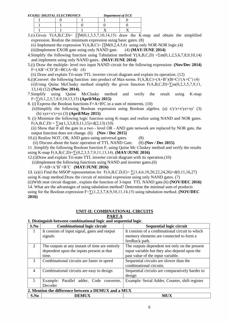
1 0 1 1 0 1 1 0 0 0 1 1 1 X X
3.(i).Given Y(A,B,C,D)= ∏M(0,1,3,5,7,10,14,15) draw the K-map and obtain the simplified
expression. Realize the minimum expression using basic gates. (8)
(ii) Implement the expression Y(A,B,C)= ∏M(0,2,4,5,6) using only NOR-NOR logic.(4)
(iii)Implement EXOR gate using only NAND gate. (4) (MAY/JUNE 2014)
4.Simplify the following function using Tabulation method Y(A,B,C,D) =m(0,1,2,5,6,7,8,9,10,14)
and implement using only NAND gates. (MAY/JUNE 2014)
5.(i) Draw the multiple- level two input NAND circuit for the following expression: (Nov/Dec 2014)
F=(AB’+CD’)E+BC(A+B) (4)
(ii) Draw and explain Tri-state TTL inverter circuit diagram and explain its operation. (12)
6.(i)Convert the following function into product of Max-terms. F(A,B,C)=(A+B’)(B+C)’(A+C’) (4)
(ii)Using Quine McClusky method simplify the given function F(A,B,C,D)=∑m(0,2,3,5,7,9,11,
13,14) (12) (Nov/Dec 2014).
7.Simplify using Quine McClusky method and verify the result using K-map
F=∑(0,1,2,5,7,8,9,10,13,15) (April/May 2015)
8. (i) Express the Boolean functions F=A+B'C in a sum of minterms. (10)
(ii)Simplify the following Boolean expression using Boolean algebra. (a) x'y'z+x'yz+xy' (3)
(b) xyz+x'z+yz (3) (April/May 2015)
9. (i) Minimize the following logic function using K-maps and realize using NAND and NOR gates.
F(A,B,C,D) = ∑m(1,3,5,8,9,11,15)+d(2,13) (10)
(ii) Show that if all the gate in a two - level OR - AND gate network are replaced by NOR gate, the
output function does not change. (6) (Nov / Dec 2015)
10.(i) Realize NOT, OR, AND gates using universal gates. (8)
(ii) Discuss about the basic operation of TTL NAND Gate. (8) (Nov / Dec 2015)
11 .Simplify the following Boolean function F, using Quine Mc Cluskey method and verify the results
using K-map F(A,B,C,D)=∑(0,2,3,5,7,9,11,13,14). (MAY/JUNE 2016)
12.(i)Draw and explain Tri-state TTL inverter circuit diagram with its operation.(10)
(ii)Implement the following functions using NAND and inverter gates.(6)
F=AB+A’B’+B’C (MAY/JUNE 2016)
13. (a)(i) Find the MSOP representation for F(A,B,C,D,E)= ∑(1,4,6,10,20,22,24,26)+d(0,11,16,27)
using K-map method.Draw the circuit of minimal expression using only NAND gates. (7)
(ii)With neat circuit diagram , explain the function of 3-input TTL NAND gate.(6) (NOV/DEC 2016)
14. What are the advantages of using tabulation method? Determine the minimal sum of products
using for the Boolean expression F=∑(1,2,3,7,8,9,10,11,14,15) using tabulation method. (NOV/DEC
2016)
UNIT-II: COMBINATIONAL CIRCUITS
PART A
1. Distinguish between combinational logic and sequential logic.
S.No Combinational logic circuit Sequential logic circuit 1 It consists of input signal, gates and output
signals It consists of a combinational circuit to which
memory elements are connected to form a
feedback path. 2 The outputs at any instant of time are entirely
dependent upon the inputs present at that
time.
The outputs dependent not only on the present
input variable but they also depend upon the
past value of the input variable. 3 Combinational circuits are faster in speed Sequential circuits are slower than the
combinational circuits. 4 Combinational circuits are easy to design Sequential circuits are comparatively harder to
design 5 Example: Parallel adder, Code converter,
Decoder Example: Serial Adder, Counter, shift register
2. Mention the difference between a DEMUX and a MUX
S.No DEMUX MUX

EC6302: DIGITAL ELECTRONICS Department of ECE
7
1 A demultiplexer is a circuit that receives
information on a single line and transmits
this information on one of many output lines
A digital multiplexer is a combinational circuit
that selects binary information from one of many
input lines and directs it to a single output line. 2 Data Distributor Data selector 3 Block diagram:
3. State the condition to check the equality of two n-bit binary numbers A and B.
A = An-1 ……. A3 A2 A1 A0 , B = Bn-1 ……. B3 B2 B1 B0. The two numbers are equal if all pairs of
significant bits are equal. The equality relation of each pair of bits can be expressed logically with an
equivalence function (X-NOR): Xi = AiBi + Ai’Bi’ where i = 0, 1, 2, 3, …….(n-1)
The condition to check the equality of two n-bit binary numbers is R(A=B) = Xn-1 Xn-2 …….. X3X2X1X0.
If R(A=B) =1, the two numbers A and B are equal, otherwise they are unequal.
4. How does an encoder differ from a decoder?
S.No Decoder Encoder 1 Block diagram:
2 A decoder is a combinational circuit that
converts binary information from n input
lines to a maximum of 2n unique output lines.
An encoder is a digital circuit that performs
the reverse operation of a decoder. An
encoder has 2n input lines and n output lines. 3 A decoder accepts a set of binary inputs and
activates only the output that corresponds to
that input number.
An encoder generates the binary code
corresponding to the input activated.
4 Example: Binary to Octal decoder Example: Octal to Binary encoder. 5. Draw the logic diagram of a one to four line demultiplexer. (May/June 2013)
1 to 4 line Demultiplexer:
6. Draw a 2 to 1 multiplexer circuit.
7. Distinguish between a decoder and a demultiplexer. (May/June 2015)
S.No DEMUX DECODER
Single
Input
1 X 2n
DEMUX 2n Outputs
n selection inputs
2n X 1
MUX Single
output 2n Intputs
n selection
inputs
n X 2n
Decoder 2n Outputs n Intputs
2n X 1
Encoder 2n Intputs n Outputs

EC6302: DIGITAL ELECTRONICS Department of ECE
8
1. A demultiplexer is a circuit that receives
information on a single line and transmits
this information on one of many output lines
A decoder accepts a set of binary inputs
and activates only the output that
corresponds to that input number. 2. Data Distributor Decoder with enable input is used as
demultiplexer.
8. Implement 2 input NAND gate function y = (AB)’ using a 2:1 MUX.
Truth table Implementation table
A B y 0 0 1 0 1 1 1 0 1 1 1 0
9. Realize AND and OR function using 2:1 MUX.
Implementation of AND function:
A B y 0 0 0 0 1 0 1 0 0 1 1 1
Implementation of OR function:
Truth table
A B y 0 0 0 0 1 1 1 0 1 1 1 1
10. Give some of the major applications of multiplexers.
Data selection, Data routing, Operation sequencing, Parallel to serial conversion, Waveform
generation, Logic-function generation.
11. What is priority encoder? (May/June 2014, Nov/Dec 2015)
A priority encoder is an encoder circuit that includes the priority function. The operation of the
priority encoder is such that if two or more inputs are activated at the same time, the output binary
code will be generated to the highest-numbered input.
12. Using a single IC 7485, draw the logic diagram of a 4-bit comparator.
A3 A2 B0 B1 A1 A0 B3 B2
IA > B
IA < B
IA = B
OA = B OA < B OA > B
+5V
A B
0V 4-bit Comparator
IC 7485
0
2
1
3
A’
A
1 A’
I0 I1
2 X 1
MUX
1
A’
y
B
Logic
diagram
2
2 X 1
MUX
0
A
y
B
Logic
diagram
0 1
3
A’
A
0 A
I0 I1
2 X 1
MUX A
1
y
B
Logic diagram
0
3
A’
A
A 1
I0 I1
1
2

EC6302: DIGITAL ELECTRONICS Department of ECE
9
13. How can a DEMUX be used as a decoder?
The selection lines of the DEMUX can be used as input lines of decoder and if the data input of the
demultiplexer is used as the enable input of the decoder then we can use the demultiplexer as a
decoder.
14. Design a combinational logic circuit that will allow input signal A to pass through to the
output when the control inputs B and C are different, otherwise the output is high.
Y=A + (BOC)
15. Realize XOR function using only NAND gates.
16. Draw the 4 bit Gray to Binary code converter.
17. Draw the 4 bit Binary to Gray code converter.
18. Obtain the expression for sum and carry output of a full adder and implement the same.
S=Z⊕ (X⊕ Y) = Z'(XY'+X'Y) + Z(XY'+X'Y)'.
= Z'(XYM-X'Y) + Z(XY+X'Y').
= XY'Z'+X'YZ'+XYZ+X'Y'Z.
C = XY'Z+X'YZ+XY.
19. Implement half Adder using NAND Gates. (May/June 2013)
ABC Output
000
001
010
011
100
101
110
111
1
0
0
1
1
1
1
1
BC
A 00 01 11 10
1
0
0
1
1
3
0
2
1
4
1
5
1
7
1
6
1
0

EC6302: DIGITAL ELECTRONICS Department of ECE
10
20. Give the truth table for half adder and write the expression for sum and carry? (Nov/Dec
2015)
A half adder is a logical circuit that performs an addition operation on two binary digits. The half
adder produces a sum and a carry value which are both binary digits. The drawback of this circuit is
that in case of a multibit addition, it cannot include a carry. S=A⊕B, C= A.B. Following is the logic
table for a half adder:
21. Draw the logic circuit of a 2 bit comparator. (May/June 2014).
22. Draw the two bit comparator circuit using logic gates. (May/June 2015).
23.Construct a 4-bit parallel adder/subtractor circuit using Full adders and XOR gates.
(Nov/Dec 2014).
S-Select input. S=0 addition operation, S=1 subtraction operation.
24. List the applications of decoders. 1. Decoders are used in counter systems, 2. Decoders are used for A/D conversion,
3. Decoders are used for D/A conversion, 4.Decoders are used in seven segment digital displays.
25. Convert a two-to-four line decoder with enable input to 1X4 demultiplexer (Nov/Dec 2014).
A B C S
0 0 0 0
0 1 0 1
1 0 0 1
1 1 1 0

EC6302: DIGITAL ELECTRONICS Department of ECE
11
25. Write the design procedure of combinational circuit. (MAY/JUNE 2016) (NOV/DEC 2016)
The design procedure for combinational logic circuits starts with the problem specification and
comprises the following steps:
1. Determine required number of inputs and outputs from the specifications.
2. Derive the truth table for each of the outputs based on their relationships to the input.
3. Simplify the boolean expression for each output. Use Karnaugh Maps or Boolean algebra.
Draw a logic diagram that represents the simplified Boolean expression. Verify the design by
analysing or simulating the circuit.
26. Draw the combinational circuit that converts 2 coded inputs into 4 coded outputs.
(MAY/JUNE 2016)
27. Draw the logic diagram and truth table of Full adder. (NOV/DEC 2016)
INPUT OUTPUT A B Cin S Cout 0 0 0 0 0 0 0 1 1 0 0 1 0 1 0 0 1 1 0 1 1 0 0 1 0 1 0 1 0 1 1 1 0 0 1 1 1 1 1 1
PART B
1. (i) Design a BCD adder to add two BCD digits.(or) Design a 4-bit decimal adder using 4-bit binary
adders.(10) (May/June 2013, Nov/Dec 2014).
(ii) Implement the following functions using Multiplexers. F(A,B,C,D)= ∑m(0,1,3,4,8,9,15) (6)
2. (i) Explain in detail a 4 – bit parallel adder/subtractor. (8)
(ii) How can a full adder be constructed with two half adders and one OR gate. (8)
3. Design and explain the working of a Half subtractor and full subtractor. (16) (Nov/Dec 2012)
4. (i) Draw the logic diagram of binary to octal decoder and explain the working in detail. (8)
(ii) How is carry lookahead adder faster than a ripple carry adder? Explain in detail with neat
sketches. (8) (April/May 2015)
5. Design a 4bit magnitude comparator and draw the circuit (May/June 2013)
6. (i)Design a 3:8 decoder using basic gates. (8)
(ii) Design a binary to gray code converter. (8) (May/June 2014)
7. (i)Design a Full subtractor using Demultiplexer. (8)
(ii)Explain the working of carry-lookahead adder. (8) (May/June 2014)

EC6302: DIGITAL ELECTRONICS Department of ECE
12
8. (i).Design 4-bit magnitude comparator with three outputs A>B, A<B and A=B.(12)
(ii)Construct a 4-bit even parity generator circuit using logic gates.(4)(Nov/Dec 2014).
9. Explain with the neat diagram the function of the Binary multiplier
(i) using shift method (8)
(ii) parallel multiplier (8) (Nov/Dec 2015)
10.Design a BCD to excess-3 code converter using minimum number of NAND gates. (Nov/Dec
2015) 11.(i)Design 4 * 1 multiplexer circuit. (8)
(ii) Implement the function using multiplexer F = ∑(0,1,3,4,8,9,15) (8) (April/May 2015)
12.(i)Design a 4-bit magnitude comparator with 3 outputs: A>B,A<B,A=B.(8)
(ii) Design a 4-bit binary to gray code converter.(8) (MAY/JUNE 2016)
13.(i)Implement the following Boolean function using 8×1 multiplexer.
F(A,B,C,D)= ∑(1,3,4,11,12,13,14,15).(8)
(ii)Explain the concept of carry look ahead adder with neat diagram.(8) (MAY/JUNE 2016)
14. (i)Design and explain 1 of 8 demultiplexer (8)
(ii)What is parity checker? (5) (NOV/DEC 2016)
15. Describe the operation of 3-bit magnitude comparator. (NOV/DEC 2016)
16. Design an even parity generator that generates an even parity bit for every input string of 3-bits.
(NOV/DEC 2016)
UNIT:III SEQUENTIAL CIRCUITS
PART A
1. Give the excitation table of J-K flip flop.
Q Q(t+1) J K 0 0 0 X 0 1 1 X 1 0 X 1 1 1 X 0
2. Give the truth table for J-K flip-flop.
Q J K Q(t+1) 0 0 0 0 0 0 1 0 0 1 0 1 0 1 1 1 1 0 0 1 1 0 1 0 1 1 0 1 1 1 1 0
3. What is meant by the term edge triggered? (or) What is the edge - triggered flip - flop? (Nov /
Dec 2015) Output transitions occur at a leading edge or a trailing edge of the clock pulse
4. Write the characteristics table of a D flip flop.
Q D Q(t+1) 0 0 0 0 1 1 1 0 0 1 1 1
5. Show the T flip-flop implementation from S-R flip-flop. (May/June 2013)
T Flip-Flop Implementation using SR Flip-Flop:
6. With reference to a JK flip-flop, what is racing? (NOV/DEC 2016)
Because of the feedback connection in the JK flip-flop, when both J & K are equal to 1 at the
same time, the output will be complemented while activating the clock pulse. The output is

EC6302: DIGITAL ELECTRONICS Department of ECE
13
complemented again and again if the pulse duration of the clock signal is greater than the signal
propagation delay of the JK flip-flop for this particular input combination (J=K=1) There is a race
between 0 and 1 within a single clock pulse. This condition of the JK FF is called race-around
condition or racing.
7. Give the truth table of T flip flop.
Q T Q(t+1) 0 0 0 0 1 1 1 0 1 1 1 0
8. What is shift register? Shift register: A register capable of shifting its binary information either from right to left or
left to right is known as shift register. It consists of flip-flops connected is cascade. All flip-flops
receive a common clock pulse which causes the shift from one stage to the next stage. It is of four
basis types:
1. Serial in serial out register, 2. Serial in parallel out register, 3. Parallel in serial out register
4. Parallel in parallel out register.
Bi-directional shift register and Universal shift registers are also used for different applications.
9. Why D FF is known as Delay FF?
The binary information present at the data input of the D FF is transferred to the Q output when the cp
input is enabled. The output follows the data input as long as the pulse remains in its 1 state. When the
pulse goes to 0, the binary information that was present at the data input at the time the pulse
transition occurred is retained at the Q output until the pulse i/p is enabled again. So D FF is known as
Delay FF.
10. When is a counter said to suffer from lockout?
In a counter if the next state of some unused state is again an unused state and if by chance the counter
happens to find itself in the unused states and never arrived at a used state then the counter is said to
be in the lockout conditions.
11. What is a ripple counter?
An asynchronous counter in which each flip-flop is triggered by the output of the previous flip-
flop.
12. What is the minimum number of flip-flops needed to build a counter of modulus 60?
(April/May 2015)
Modulus N < 2k , where k is the number of flip-flops , Modulus 60 < 26 = 64, k = 6. The
minimum number of flip-flops needed to build a counter of modulus 60 is 6.
13. What is a universal shift register?
A register may operate in any of the following five modes: SISO, SIPO, PIPO, PISO,
Bidirectional. If a register can be operated in all the five possible ways, it is known as Universal
Shift Register.
14. How race around condition can be eliminated?
Race around condition can be eliminated in JK latch by two ways:
1. Using the edge triggered J-K flip-flop.
2. Using the master slave J-K flip-flop.
15. Mention the uses of shift registers.
Storage Device: The primary use of shift register is temporary data storage.
Time delay generation: A SISO shift register can be used to introduce time delay TD between the
input and the output digital signals. The time delay can be given as TD = N x (1/fc) Where N is the
number of stages and fc is the clock frequency. Serial-to-Parallel Converter (SIPO), Parallel-to-
serial Converter (PISO).
Shift register counter: A shift register with the serial output connected back to the serial input is
called shift register counter. Because of such a connection, special specified sequences are
produced as the output. The most common shift register counters are the ring counter and the
Johnson counter.
16. What are Mealy and Moore machines? (or) What are the classifications of sequential
circuits? (Nov /Dec 2015)
Mealy and Moore machines are two models of clocked or synchronous sequential circuit.
Mealy machine: The output depends on both the present state of the flip-flops and on the inputs.
Moore machine: The output depends only on the present state of the flip-flops.

EC6302: DIGITAL ELECTRONICS Department of ECE
14
17. The clock frequency is 2MHz. How long will it take to serial load the eight shift register? (Given) fCLK = 2MHz. n = 8
Time taken to load serially the eight bit will be given by
= 𝑛 × 1
𝑓𝐶𝐿𝐾
= 8 × 1
2 × 106= 4 × 10−6 = 4 𝜇𝑠𝑒𝑐
18. What is flip-flop? Flip-flop : Flip-flop is a sequential circuit which is used to store single bit of information at a
time i.e. either ‘1’ or ‘0’ at a time. It has two stable output states. It can stay in one of the two
stable states unless state is changed by applying external inputs. Thus, it is a basic memory
element for storage of data in binary form. There are various types of flip-flops:
1. SR flip flop, 2. JK flip-flop,
3. D flip flop, 4. T flip-flop.
19. What is a state diagram? (May/June 2014).
State diagram is the graphical representation of state table of sequential logic circuits. In the state
diagram, a state is represented by a circle and the transition between states is indicated by directed
lines connecting the circles. The directed lines are labeled with two binary numbers separated by a
slash. The input value during the present state is labeled first and the number after the slash gives the
output during the present state.
Example:
20. What do you meant by the term state reduction problem?
The reduction of the number of flip-flops in a sequential circuit is referred to as the state –
reduction problem. State – reduction algorithms are concerned with procedures for reducing the
number of states in a state table while keeping the external input – output requirements
unchanged.
21.Give difference between latch and flip-flop.
Latch Flip-Flops 1. Latch has an enable input. 1. Flip-flops has a clock signal. 2. As long as enabled input is active, the latch
output will keep changing according to the
input.
2. Flip-flop samples its inputs and changes its
outputs only at a particular instant of time i.e.
when clock is provided. 22. Differentiate between sequential and combinational circuits (April/May 2015)
S.No. Combinational Circuits Sequential Circuits 1 Output depends only on the present values
of the input. Output depends on the present and past
values of the input. 2 Feedback path is not used in combinational
circuits. Feedback path is used in Sequential
circuits. 3 Memory element is not present. Memory element is present. 4 Clock is not used in combinational circuits. Clock is used in combinational circuits. 5 Circuit is simple. Circuit is complex. 6 Example: Adders, Subtractors, code
converters, comparator etc. Example: Flip flops, counters, registers
etc. 23. Differentiate between synchronous and asynchronous counters. (or) How does ripple
counter differ from synchronous counter? (or) Compare the logics of synchronous counter and
ripple counter. (May/June 2014) (MAY/JUNE 2016)
Synchronous Counter Asynchronous Counter
00
10
11 01
0/ 0
0/1 1/ 1
1/ 1
1/ 0 0/ 0
1/ 0 0/ 1

EC6302: DIGITAL ELECTRONICS Department of ECE
15
1. Simultaneous clock pulse is given to
all the flip-flop.
1.Clock pulse is given to first flip-flop and the
output of first flip-flop acts as a clock to the next
and so on.
2. Fast as compare to asynchronous
counters. 2. Slow as compare to synchronous counters
because 2nd flip-flop has to wait until the 1st flip-
flop gives the output.
3. Additional combinational circuit is
required for its designing. This circuit
becomes complex.
3. Circuit is simple as compared to synchronous
counters.
4. Frequency of operation can be much
higher than the asynchronous counters. 4.Frequency of operation is lesser than the
synchronous counters.
5. Parallel Counter 5.Serial counter
24.Draw the logic diagram of clocked SR flip-flop. Draw the truth table of RS flip flop.
(Nov/Dec 2015, May/June 2014)
25. Give expression for maximum frequency of operation of n-bit Asynchronous and
synchronous counters. Time period of clock (Tclk) ≥ N * tpd.
N = no. of FFs, tpd = Propagation delay. Max. frequency of operation for asynchronous counter.
𝑓𝑚𝑎𝑥 = 1
𝑇𝑐𝑙𝑘=
1
𝑁 × 𝑡𝑝𝑑
It is same for synchronous counter unless no. of flip-flop, where the maximum frequency of
synchronous counter is
𝑓𝑚𝑎𝑥 = 1
𝑁 𝑡𝑝𝑑
26. Realize JK flip flops (Nov/Dec 2014).
Logic Diagram: Characteristic Equation:
Characteristic Table:
27. Give the truth table of transparent latch. (MAY/JUNE 2016) OR Draw D-latch with truth
table. (NOV/DEC 2016)
S R Output / Action 0 0 No Change 0 1 0 Reset 1 0 1 Set 1 1 Forbidder
Q J K Q(t+1) 0 0 0 0 0 0 1 0 0 1 0 1 0 1 1 1 1 0 0 1 1 0 1 0 1 1 0 1 1 1 1 0

EC6302: DIGITAL ELECTRONICS Department of ECE
16
28. Differentiate synchronous and asynchronous sequential circuits (MAY/JUNE 2016)
Synchronous Circuits Asynchronous Circuits Simultaneous clock pulse is given to all the
flip-flop.
Clock pulse is given to first flip-flop and the
output of first flip-flop acts as a clock to the next
and so on.
Fast as compare to asynchronous circuits. Slow as compare to synchronous circuits because
2nd flip-flop has to wait until the 1st flip-flop gives
the output. Additional combinational circuit is required
for its designing. This circuit becomes
complex.
Circuit is simple as compared to synchronous
circuits.
PART B
1. (i) Realize a JK flip flop using SR flip flop.(8)
(ii) Draw the logic diagram for SR, JK, D&T flip flops.(8)
2. (i) Design and explain the working of a asynchronous Decade counter.(8)
(ii) Design and explain the working of a 4 bit synchronous binary counter and draw its timing
diagram.(8)
3. Design a sequential circuit that has 3 flip-flops A, B and C, one input ‘x’ and one output ‘y’. The
circuit is to be designed by treating the unused states as don’t care conditions. Use JK flip-flops in
the design. State diagram is given below. (May/June 2014)
4. Design the sequential circuit specified by the following state diagram using T flip-flops. Check
whether your design is self-correctable. (Nov/Dec 2014).
5. i) Draw a 4 bit SISO & PIPO shift register and briefly explain.(8)
(ii) Explain the operation of 4 bit universal shift register. (8)
6. (i) Explain the working of a master slave JK flip flop.(8) (ii) Design and explain the working of
MOD-11 asynchronous counter.(8)
7.Design a Moore type sequence detector to detect a serial input sequence of 101. (May/June 2014)
8.Using D flip flops design a synchronous counter which counts in the sequence. 000,001,010,
011,100,101,110,111,000. (April/May 2015)
9.(i) Discuss the working of a 4 bit Johnson counter with neat block diagram. (8) (April/May 2015)
(ii)Explain the functioning of a recirculating shift register with various modes of operation. (8)
10.(i) Explain the operation of JK flip-flop with neat diagram . (10)
(ii)Explain the operation of master slave flip flop and show how the race around condition is
eliminated. (6) (Nov/Dec 2015)
11.Explain the operation of synchronous counter. (Nov/Dec 2015)

EC6302: DIGITAL ELECTRONICS Department of ECE
17
12.Design a 3-bit synchronous counter using D-Flip flop.
13.(i)Draw and explain the 4-bit SISO,SIPO,PISO and PIPO shift register with its waveforms.(12)
(ii)Realize D flip- flop using SR flip-flop.(4) (MAY/JUNE 2016)
14.(i) Explain the operation of JK flip flop with neat diagram.(6)
(ii)Explain the operation of serial –in –serial- out shift register.(7)
15.Design synchronous mod-6 counter. (NOV/DEC 2016)
16. Design a synchronous up/down counter. (NOV/DEC 2016)
UNIT-IV: MEMORY DEVICES
PART A
1. What is a PLA? Describe its uses.
PLA (Programmable Logic Array) is a programmable logic device with a Programmable AND array
and a programmable OR array.PLA can be used to implement complex logic circuits. It is more
economical to use PLA rather than PROM to implement logic circuits that have more number of don’t
care conditions in order to reduce number of gates. PLA is flexible compared to PROM & PAL.
2. Distinguish between EPROM and EEPROM
S.No EPROM EEPROM 1 Erasable Programmable Read Only
Memory Electrically Erasable Programmable Read
Only Memory 2 Placing the EPROM chip under a special
ultraviolet erases the stored information. Applying electrical signal erases the stored
information. 3 It can also be called as UV EPROM It can also be called as Electrically Alterable
ROM (EAROM). 3. How does the architecture of a PLA differ from a PROM? (or) What is programmable logic
array? How it differs from ROM? (Nov / Dec 2015) (NOV/DEC 2016) The programmable logic array (PLA) is a programmable logic device with a programmable OR
array and a programmable AND array. The Programmable Read Only Memory (PROM) is a
programmable logic device with a fixed AND array and a programmable OR array. Architecture: PAL
Architecture: PROM
4. Define Bit time & Word time.
The time interval between clock pulses is called the bit time, and the time required to shift the entire
contents of a shift register is called the word time.
5. What is non- volatile memory?
Memory units that retain its stored information after removal of power. Eg magnetic disk. This is
because the data stored on magnetic components is manifested by the direction of magnetization,
which is retained after power is turned off.
6. What does burning a ROM mean?
The process of entering data into the ROM by burning internal fuses is called programming or
burning a ROM.
7. What are the major drawbacks of the EEPROM?
COST: In EEPROM, the erasing and programming of an EEPROM can be done in circuit. (Without
using separate UV light source and special PROM programmer unit). Because of this on- chip support
circuitry the EEPROM is available with more cost.
DENSITY: The high level integration of the EEPROM occupies more space. For example, 1-Mbit
EEPROM requires about twice as much silicon as a 1-Mbit EPROM.
8. How many data inputs, data outputs and address inputs are needed for a 1024 4 ROM?
No. of data inputs and outputs = 4, 1024 = 210 , No of address inputs = 10
9. Describe the basic functions of ROM and RAM. (or) What is the basic difference between
RAM and ROM circuitry. (April / May 2015)
ROM: Read only memory is used to store information permanently. The information cannot be
altered. RAM: Random Access Memory is used to store information. The information can be read
form it and the new information can be written into the memory.
Programmable
AND array
Programmable
OR Array output input
Fixed AND array Programmable
OR Array output input

EC6302: DIGITAL ELECTRONICS Department of ECE
18
10. How long will it take to erase UV erasable EPROM completely?
15 to 20 min.
11. What is an EAROM?
EAROM: Erasable Alterable Read Only Memory. The stored information is erased by applying
electrical signal.
12. What is Configurable Logic Block?
The programmable logic blocks in the Xilinx family of FPGAs are called configurable logic
blocks (CLBs). The CLB of Xilinx 3000 series can be configured to perform any logic function of up
to a maximum of seven variables. .
13. Give the different types of RAM.
RAM can be classified into two types:
Static RAM: The storage elements used in this type RAM are latches (unclocked FFs).
Dynamic RAM: A dynamic RAM is one in which data are stored on capacitors which require
periodic recharging (refreshing) to retain the data. RAMs are manufactured with either bipolar or
MOS technologies. Bipolar RAMs are all static RAM. MOS RAM are available in both static and
dynamic types
14. What is Memory refresh?
Dynamic RAMs are fabricated using MOS technology. They store 1s and 0s as charges on a
small MOS capacitor (typically a few picofarads). Because if the tendency for these charges to
leak of after a period of time, dynamics require periodic recharging of the memory cells This is
called refreshing the dynamic RAM or memory refresh.
15. What is Field Programmable Gate Array device(FPGA) device (Nov/Dec 2014).
A field-programmable gate array (FPGA) is an integrated circuit designed to be configured by a
customer or a designer after manufacturing – hence "field-programmable". The FPGA
configuration is generally specified using a hardware description language (HDL), similar to that
used for an application-specific integrated circuit (ASIC).FPGAs contain an array of
programmable logic blocks, and a hierarchy of reconfigurable interconnects that allow the blocks
to be "wired together" – , like many logic gates that can be inter-wired in different configurations.
Logic blocks can be configured to perform complex combinational functions, or merely simple
logic gates like AND and XOR. In most FPGAs, logic blocks also include memory elements,
which may be simple flip-flops or more complete blocks of memory.
16. Distinguish between Bipolar RAM cell and MOSFET RAM cell.
Bipolar RAM cell is a latch which is manufactured with bipolar technology (using BJT). They are all
static RAMs. MOSFET RAM cell a storage element which is manufactured with MOS technology
(MOSFET). Capacitors are provided by metal oxide semiconductor (MOS).
17. What is the difference between PAL and PLA?
PLA PAL In case of PLA i.e. programmable logic array
both AND and OR arrays are programmable. In case of PLA i.e. programmable array logic
AND array are programmable and OR arrays are
fixed. It is costlier as compared to PAL. It is cheaper. It is complex than PAL. It is simple. It can't easily be programmed. It is easy to program a PAL 18. What do you mean by PLD’s? or List the advantages of PLDs(MAY/JUNE 2014)
PLDs: Programmable logic devices are the special type of IC’s used by the USE and are
programmed before use Different type of logic functions can be implemented using a single
programmed IC chip of PLD’s. PLD s can be reprogrammed because these are based on re-writable
memory technologies Fuse links are used to programmed the PLD b the user according to the type of
PLD to be manufactured.
19. On what basis do we characterize various type of memories. Memories can be characterize on various parameters.
1. Characterize based on Principle of operation., 2. Characterize based on Physical characteristics.
3. Characterize based on Mode of Access.,4. Characterize based on Fabrication Technology.
20. What are the characteristics of memories? Characteristics of memory: 1. Memory organization and capacity, 2. Physical dimensions,
3. Packing of memory, 4. Power consumption,5.Cost etc.
21.Compare and contrast EEPROM and flash memory (Nov/Dec 2014) (NOV/DEC 2016).

EC6302: DIGITAL ELECTRONICS Department of ECE
19
Flash and EEPROM are very similar, but there is a subtle difference. Flash and EEPROM
both use quantum cells to trap electrons. Each cell represents one bit of data. The presence or
absence of electrons in a cell indicates whether the bit is a 1 or 0. The cells have a finite life - every
time a cell is erased, it wears out a little bit. In EEPROM, cells are erased one-by-one. The only cells
erased are those which are 1 but need to be zero. But Flash can erase an entire block of data. Flash
memory can only write to an entire chunk, or "sector", of memory at a time.
22. Compare a static and dynamic RAM cell.(April/May 2015)
Static RAM: No refreshing, 6 to 8 MOS transistors are required to form one memory cell, Information
stored as voltage level in a flip flop.
Dynamic RAM: Refreshed periodically, 3 to 4 transistors are required to form one memory cell,
Information is stored as a charge in the gate to substrate capacitance.
23. How does the architecture of a PAL differ from a PROM. Programmable Array Logic (PAL) is a programmable logic device with a fixed OR array and a
programmable AND array. Because only the AND gates are programmable, the PAL is easier to
program, is not flexible as the PLA. It uses array logic symbol.
The Programmable Read Only Memory (PROM) is a programmable logic device with a fixed AND
array and a programmable OR array.
24. What is Read and write operation? (Nov / Dec 2015)
Write operation: puts data into a specified address in the memory. Read operation: takes data out of a
specified address in the memory
25. Draw the structure of a Static RAM cell. (May/June 2014)
26. Give the classification of Programmable logic devices. (MAY/JUNE 2016)
Programmable logic array (PLA)
Programmable array logic (PAL)
Generic array logic (GALS)
Complex programmable logic device (CPLD)
Field-programmable gate array (FPGA)
27. How the bipolar RAM cell is different from MOSFET RAM cell. (MAY/JUNE 2016)
1.MOS have less leakage current than BJT. So power consumption is less.
2.MOS transistor has smaller size than BJT. So it gives high packing density.
3.MOS fabrication has less number of fabrication steps than BJT. Also fabrication of MOS is
much simpler than BJT.
PART B
1. (i) Explain memory decoding. (8)
(ii) Draw a RAM cell and explain its working in detail. (8) (April/May 2015)
2. (i) Implement using ROM a combinational logic circuit which can find 2’s complement of 3bit
binary number.(8) (ii) Using ROM, implement a combinational circuit which accepts a 3 bit number
and generates an output binary number equal to square of input number. (8)
3. (i) Implement the functions using PAL W=m(2,12,13), X=m(7,8,9,10,11,12,13,14,15),
Y= m(0,2,3,4,5,6,7,8,10,11,15), Z= m(1,2,8,12,13) (10) (May/June 2013)
(ii) Implement Full adder and full subtractor using ROM (6)
4. (i) A combinational circuit is defined by the functions F1 = m(3,5,7), F2 = m(5,6,7) Implement
the circuit with a PLA having 3 inputs,3 product terms and 2 outputs.(10)
(ii) Draw the PLA implementation table for the Boolean expressions F1 = x’z + y’z’,F2 = x’y + x’
z + xy’ (6) (Nov/Dec 2012)
5. Design and explain a 32x8 ROM (May/June 2013)
6.(i)Explain the read cycle and write cycle timing parameters of a RAM with the help of timing
diagram.

EC6302: DIGITAL ELECTRONICS Department of ECE
20
(ii) Draw the dynamic RAM cell and explain its operation. (8) (May/June 2014).
7.Design a BCD to Excess 3 code convertor using a PLA(May/June 2014).
8.(i)Write short notes on EAPROM and static RAM cell using MOSFET (6) (Nov/Dec 2014).
(ii)Using 8 64X8 ROM chips with an enable input and decoder construct a 512X8 ROM.(10)
9.(i)Use PLA with 3-inputs 4 AND terms and two outputs to implement the following Boolean
functions. F1(A,B,C)= ∑m(3,5,6,7) , F2(A,B,C)= ∑m(1,2,3,4) (12)
(ii)Compare and contrast PLA and PAL. (4) (Nov/Dec 2014).
10. Write short notes on with suitable schematic: (i) Programmable Logic Array (PLA). (ii) Field
Programmable Gate Arrays. (FPGA) (April/May 2015)
11.Write the difference between static and dynamic RAM. Draw the circuits of one cell of each and
explain its working. (Nov/Dec 2015)
12.Write notes on: (i) PAL (8), (ii) FPGA (8) (Nov/Dec 2015)
13.(i)Implement the following function using PLA.(12)
F1(X,Y,Z)= ∑m(1,2,4,6)
F2(X,Y,Z)= ∑m(0,1,2,6,7)
F3(X,Y,Z)= ∑m(2,6)
(ii)Write short notes on FPGA.(4) (MAY/JUNE 2016)
14.(i)Explain memory READ and WRITE operation with neat timing diagram.(8)
(ii)Explain the organization of ROM with relevant diagrams.(8) (MAY/JUNE 2016)
15.Differentiate static and dynamic RAM. Draw the circuits of one cell of each and explain its
working principle. (NOV/DEC 2016)
16.Write short notes on : (i)PAL (ii)FPGA (NOV/DEC 2016)
UNIT-V: SYNCHRONOUS AND ASYNCHRONOUS SEQUENTIAL CIRCUIT
PART A
1. Explain the fundamental mode of operation. Asynchronous sequential circuits must be allowed to attain a stable state before the input is changed
to a new value. Because of delays in the wires & the gate circuits, it is impossible to have two or more
input variables change at exactly the same instant of time without an uncertainty as to which one
changes first. Therefore, simultaneous changes of two or more variables are usually prohibited. This
restriction means that only one input variable can change at any one time & the time between two
input changes must be longer than the time it takes the circuit to reach a stable state. This type of
operation is defined as fundamental mode.
2. What is asynchronous sequential circuit? Asynchronous sequential circuit is a system which depends upon the order in which its input
signals change and can be affected at any instant of time. The memory elements used are time
delay devices.
3. What is the difference between synchronous and asynchronous sequential circuits?
S.No Synchronous sequential circuits Asynchronous sequential circuits 1 The change of internal state occurs in
response to a clock pulse. The change in internal state occurs whenever
there is a change in input variable. 2 Memory elements are clocked flip-
flops Memory elements are unclocked flip-flops or
Time delay units. 3 The present state is totally specified by
FF values and does not change if input
changes while clock pulse is inactive
There is no clock pulse. Because of absence of
clock, asynchronous circuits are faster than
synchronous circuits. 4 Design is easy. Design is more difficult because of the timing
problems involved in the feedback path. 4. Distinguish between fundamental mode circuits and pulse-mode circuits.
Fundamental Mode Circuit
The input variables change only when the circuit is stable; Only one input variable can change at a
given time; Inputs are levels and not pulses.
Pulse mode circuit
The input variables are pulses instead of levels.; The width of the pulses is long enough for the circuit
to respond to the input.; The pulse width must not be so long that it is still present after the new state
is reached and cause a faulty change of state.; No two pulses should arrive at the input lines
simultaneously.
5. Why is the pulse mode operation of asynchronous sequential circuits not very popular?
EC6302: DIGITAL ELECTRONICS Department of ECE
21
Because of the input variable pulse width restrictions, pulse mode circuits are difficult to design. For
this reason the pulse mode operation of asynchronous sequential circuits is not very popular.
6. Define Flow table. During the design of asynchronous sequential circuits, it is more convenient to name the states by
letter symbols without making specific reference to their binary values, such a table is called a Flow
table.
7. What do you understand by Race condition? A race condition is said to exist in an asynchronous sequential circuit when two or more binary state
variables change value in response to a change in an input variable. When unequal delays are
encountered, a race condition may cause the state variables to change in an un predictable manner.
8. Explain non- critical race. (NOV/DEC 2016)
The order by which the state variables change may not be known in advance. If the final stable state
that the circuit reaches does not depend on the order in which the state variable change, the race is
called a non-critical race.
9. Explain critical race.(or) What is critical race condition in asynchronous sequential circuits?
Give an example (Nov/Dec 2014). (MAY/JUNE 2016) (NOV/DEC 2016)
Critical race in asynchronous circuits occur between two signals that are required to change at the
same time when the next stable state is dependent on the delay paths in the circuit. If it is possible to
end up in two or more different stable states, depending on the order in which the state variable
change, then it is called a critical race.
10. Define the term Maximal compatible.
The maximal compatible is a group of compatibles that contains all the possible combinations of
compatible states. The maximal compatible can be obtained from a merger diagram.
11. What do you meant by the term Hazard? Define Static -1 Hazard. (Nov/Dec 2015)
(MAY/JUNE 2016) (NOV/DEC 2016) Hazards are unwanted switching transients that may appear at the output of a circuit because
different paths exhibit different propagation delays. Hazards occur in combinational circuits,
where they may cause a temporary false output value. When this condition occurs in
asynchronous sequential circuits, it may result in a transition to a wrong stable state. Steps must
be taken to eliminate this effect.
Static 1-hazard: The output may momentarily go to 0 when it should remain 1.
12. Differentiate Static & Dynamic Hazard. (Nov/Dec 2012)(MAY/JUNE 2016)(NOV/DEC 2016)
Static 1-hazard: The output may momentarily go to 0 when it should remain 1.
Static 0-hazard: The output may momentarily go to 1 when it should remain 0.
Dynamic hazard causes the output to change three or more times when it should change from 1 to 0
or from 0 to 1.
13. Define closed covering.
The condition that must be satisfied for row merging is that the set of chosen compatibles must cover
all the states that must be closed. The set will cover all the states if it includes all the states of the
original state table. The closure condition is satisfied if there are no implied states or if the implied
states are included within the set. A closed set of compatibles that covers all the states is called a
closed covering.
14. Explain Shared Row method.
The method of making race free assignment by adding extra rows in the flow table is sometimes
referred to as Shared Row method.
15. Define Merger diagram.
The merger diagram is a graph in which each state is represented by a dot placed along the
circumference of a circle. Lines are drawn between any two corresponding dots that form a
compatible pair. All possible compatibles can be obtained from the merger diagram by observing
the geometrical patterns in which states are connected to each other.
16. Define Essential Hazard. What is the reason for essential hazard to occur?
An essential Hazard is caused by unequal delays along two or more paths that originate from the same
input. An excessive delay through an inverter circuit in comparison to the adding redundant gates as
in static hazards. To avoid essential hazard, each feedback loop must be handled with individual care
to ensure that the delay in the feedback path is long enough compared to delays of other signals that
originate from the input terminals.
17. Explain the use of SR latches in asynchronous sequential circuits.

EC6302: DIGITAL ELECTRONICS Department of ECE
22
The use of SR latches in asynchronous circuits produce a more orderly pattern, which may result in a
reduction of the circuit complexity. An added advantage is that the circuit resembles the synchronous
circuit in having distinct memory elements that store & specify the internal states. One of the ways to
avoid static hazards in asynchronous sequential circuits is to implement the circuit with SR latches.
18. Define Primitive Flow table.
A primitive flow table is a flow table with only one stable total state in each row.
19. What is finite state Machine? A finite state machine (or finite automation) is an abstract model describing the synchronous
sequential machine and its spatial counter, part, the iterative network.
20. What is State Assignment? (or) What is the most important consideration in making state
assignments for asynchronous network? (April/May 2015)
Assigning binary values to each state that is represented by letter symbol in the flow table of
sequential circuit is called state assignment. The primary objective in choosing a proper binary state
assignment in asynchronous circuit is the prevention of critical races
21. What is the need of state reduction in sequential circuit design?
To reduce the number of flip-flops
To reduce the number of gates in the combinational circuit that drives the flip-flop inputs.
22. Define compatible states.
Two states are compatible (equivalent) if in every column of the corresponding rows in the flow table,
there are identical or equivalent next states and if there is no conflict in the output values.
23. What is One-Hot assignment?
One hot state assignment is made so that only one variable is active or “hot” for each row in the
original flow table. This technique requires as many state variables, as there are rows in a flow table.
Additional rows are introduced to provide single variable changes between internal state transitions.
24. Define cycle.
A cycle occurs when an asynchronous machine makes a transition through a series of unstable states.
Care must be taken to make sure whether the cycle terminated with a stable state or not. If a cycle
does not terminate with a stable state, the circuit will keep going from one unstable state to another,
making the entire circuit unstable.
25.Write the VHDL code for a half adder. (May/June 2014).
ENTITY half_adder IS --- Half Adder
PORT(a,b:IN BIT; s,c :OUT BIT);
END half_adder;
ARCHITECTURE half_adder_beh OF half_adder IS
BEGIN
s <= a XOR b; -- Implements Sum for Half Adder
c <= a AND b; -- Implements Carry for Half Adder
END half_adder_beh;
26. Define ASM chart. List its three basic elements. (Nov/Dec 2014)
The algorithmic state machine (ASM) method is a method for designing finite state machines. It is
used to represent diagrams of digital integrated circuits. The ASM diagram is like a state diagram but
less formal and thus easier to understand. An ASM chart is a method of describing the sequential
operations of a digital system. Three basic elements are 1.State box 2.Decision box and 3.Conditional
output box.
27. Draw the general model of ASM. (Nov/Dec 2015)

EC6302: DIGITAL ELECTRONICS Department of ECE
23
28. Define critical race and give methods for critical race free state assignment. (MAY/JUNE
2016)
A race condition is said to be exist in asynchronous sequential circuit when two or more
binary state variables change value in response to change in an input variable. When unequal
delays are encountered, a race condition may cause the state variables to change in an
unpredictable manner. If it is possible to end with more than one state depending on the order
of the state change then it is a critical race, which must be avoided.
The technique commonly used for making a critical race-free network is state assignment.
State assignments are classified as follows.
• Shared state assignment
• Multiple row state assignment
• One hot state assignment
PART B
1. (i) Implement the following functions by a hazard free two level AND – OR gate network.
F = X1X2’ + X2X3 (May/June 2013)
(ii) Implement the following function F (A,B,C) = ∑(0,1,3,4,8-12) by a hazard free two level OR
– AND gate network. (Nov/Dec 2012)
2. Design a gated latch circuit with two inputs G (gate) and D(data) and one output Q. Binary
information present at the D input is transferred to Q output when G=1.The Q output will follow the D
input as long as G=1;When G goes to 0,the information that was present at the D input at the time of
transition occurred is retained at the Q output. The Gated latch is a memory element that accepts the
value of D when G=1 and retains this value after G goes to 0.Once G=0, a change in D does not
change the value of the output Q.
3. Explain Race free state assignments with examples.(or) Explain different methods of race free state
assignments. (Nov/Dec 2015)
4. Describe the hazards that could occur in asynchronous sequential circuit. What are the ways in
which they get eliminated?
5. (i) An asynchronous sequential circuit is described by the following excitation and output
Y = X1X2 + (X1 + X2) Y, (a) Draw the logic diagram of the circuit,
(b) Derive the transition table and output map.
6.(i) A sequential circuit has two JK flip flops A and B. The flip flop input functions are Ja=B+X
Ka=1 Jb=A’+X’, Kb=1 and output equation Y=XA’B,
(a) Draw the logic diagram of the circuit.
(b)Tabulate the state table.
(c)Draw the state diagram.(16) (Nov/Dec 2012)
7.( i).Design a full adder using two half adders by writing Verilog program. (8)
(ii).Write Explanatory notes on Algorithms state machine (8) (May/June 2013)
8. Design a T flip-flop using logic gates. Derive the state table, state diagram, primitive flow table and
transition table and merger graph. Draw the logic circuit. (May/June 2014)
9.Design a asynchronous sequential circuit that has 2 inputs x1 and x2 and one output z. When x1=0,
output is 0.The change in x2 that occurs while x1 is 1 will cause output z=1. The output z will
remain 1 until x1 returns to 0. (May/June 2014)
10.(i)What is a Hazard in an asynchronous sequential circuits? Define static hazard, Dynamic hazard
and Essential hazard.(6)
(ii) Write and verify the HDL structural description of the four bit- register with parallel load. Use a
2X1 multiplexer for the flip-flop inputs. Include an asynchronous clear input. (10) (Nov/Dec 2014).
11. Design an asynchronous sequential circuit with inputs A and B and an output Y. Initially and at
any time if both the inputs are 0, the output, Y is equal to 0. When A or B becomes 1 and Y becomes
1. And other input also becomes 1, Y becomes 0.The output stays at 0 until circuit goes back to
initial state. (Nov/Dec 2014).
12. Design an asynchronous sequential circuit with 2 inputs T and C. The output attains a value of
T = 1 and C moves from 1 to 0. Otherwise the output is 0. (Nov/Dec 2015)
13. (i) Explain how a state graph for a sequential machine can be convened to an equivalent ASM
chart.(8)
(ii) Derive the ASM chart for binary multiplier. (8) (April/May 2015)
14. (i) When is a sequential machine said to be strongly connected. (2)

EC6302: DIGITAL ELECTRONICS Department of ECE
24
(ii) Design a sequential pattern detector that receives a stream of input bits. The circuit should
recognize the pattern 010 and produce an output whenever this pattern is received. (14) (April/May
2015)
15 .Design an asynchronous sequential circuit with two inputs X1 and X2 and with one output
Z.When X1 is 0 the output Z is 0.The first change in X2 that occurs while x1 is 1 will cause output Z
to be 1.The output Z will remain 1 until X1 returns to 0. (MAY/JUNE 2016)
16.Construct the transition table , state table and state diagram for the moore sequential circuit given
below. (MAY/JUNE 2016)
17. Explain the steps involved in the design of asynchronous sequential circuit. (NOV/DEC 2016)
18. Design an asynchronous circuit that will ouput only the second pulse received and ignore any
other pulse. (NOV/DEC 2016)