Embed Size (px)
Citation preview

10/5/2013
1
EC320 Communications TheoryInstructor: Dr. Heba A. Shaban
Lectures (Dr. Heba Shaban) 2 hours per week
Lecture/Tutorial Guidance
Tutorials (Eng. Rana Rageh) 2 hours per week

10/5/2013
2
7th week (30% weighting). Two quiz (10% weighting) 7th week exam (20% weighting)
Assessment
12th week (20% weighting). One quiz (5% weighting) 12th week exam (15% weighting)
Tutorial(10% weighting) Tutorial(10% weighting).
Final exam (40% weighting).
Introduction and types of signals
Signals section of the slides is based on EC321 course slides prepared by Dr. Amr El-Helw

10/5/2013
3
A signal is a pattern of variation of some form
A signal is a varying quantity whose value can be measured and which i f ti
What is a Signal?
conveys information.
Examples of signal include: Electrical signals
Voltages and currents in a circuit Acoustic signals
Acoustic pressure (sound) over time Mechanical signals
Velocity of a car over time Video signals
Intensity level of a pixel (camera, video) over time
Mathematically, signals are represented as a function of one or more independent variables.
For instance a black & white video signal intensity is dependent on
How is a Signal Represented?
For instance a black & white video signal intensity is dependent on x, y coordinates and time t f(x,y,t)
On this course, we shall be exclusively concerned with signals that are a function of a single variable: time/frequency
f(t)
t
10/5/2013
4
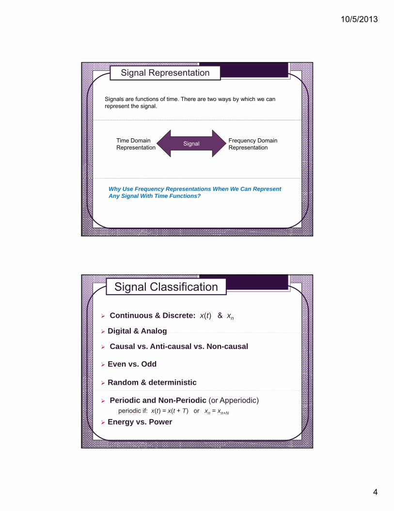
Signals are functions of time. There are two ways by which we can represent the signal.
Signal Representation
Time Domain Representation
Frequency Domain Representation
Signal
Why Use Frequency Representations When We Can Represent Any Signal With Time Functions?
Continuous & Discrete: x(t) & xn
Digital & Analog
Signal Classification
Digital & Analog
Causal vs. Anti-causal vs. Non-causal
Even vs. Odd
Random & deterministic
Periodic and Non-Periodic (or Apperiodic)periodic if: x(t) = x(t + T) or xn = xn+N
Energy vs. Power

10/5/2013
5
Continuous-Time Signals Most signals in the real world are
continuous time, as the scale isinfinitesimally fine.
Denoted by x(t), where the time(f )
x(t)
Continuous & Discrete-Time Signals
interval can be bounded (finite) orinfinite.
Discrete-Time Signals Some real world and many digital
signals are discrete time, as theyare sampled.
Contains information about thei l l t di t i t i
t
x[n]signal only at discrete points intime.
Denoted by x[n], where n is aninteger value that varies discretely.
x[n]
n
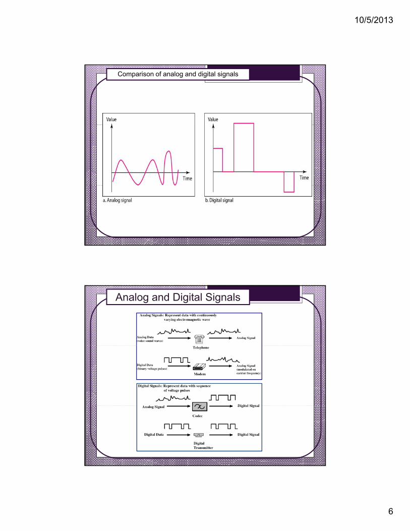
Analog signals Amplitude of analog signal can take any real or complex value at
each time/sample.
Analogue vs. Digital Signals
Digital signals They consist of pulses or digits with discrete levels or values. The
value of each pulse is constant but there is an abrupt change
1
-1
value of each pulse is constant, but there is an abrupt changefrom one digit to the next.
10/5/2013
6
Comparison of analog and digital signals
Analog and Digital Signals

10/5/2013
7
Advantages of digital signals in communication: Regenerator receiver
13
O i i l R t d
Analog and Digital Signals
Different kinds of digital signal are treated identically.
Propagation distance
V i
Originalpulse
Regeneratedpulse
DataVoice
Media
A bit is a bit!
Continuous vs. DiscreteContinuous corresponds to a
Analog vs. Digital
pcontinuous x-axis, while discretecorresponds to a discrete x-axis.
Analog corresponds to acontinuous y-axis, while digitalcorresponds to a discrete y-axis.

10/5/2013
8
Causal vs. Anticausal vs. Noncausal
Causal signals are signals that are zero for all negativetime, while anti-causal are signals that are zero for allpositive time.
Non-causal signals are signals that have nonzero valuesin both positive and negative time
A causal signal An anti-causal signal
p g
A noncausal signal
Even vs. Odd
An even signal is any signal f(t) such that f(t) = f(−t).Even signals can be easily spotted as they are symmetricaround the vertical axis.
An odd signal, on the other hand, is a signal f such thatf(t) =−(f(−t) ). Odd signals can be easily spotted as theyare symmetric around the horizontal axis.
An even signal An odd signal

10/5/2013
9
Deterministic vs. Random
A deterministic signal is a signal in which each value of the signal isfixed and can be determined by a mathematical expression, rule, ortable. Because of this the future values of the signal can becalculated from past values with complete confidence.
On the other hand, a random signal has a lot of uncertainty about itsbehaviour. The future values of a random signal cannot beaccurately predicted and can usually only be guessed based on theaverages of sets of signals
Deterministic Signal
Random Signal
Periodic vs. Aperiodic
Periodic signals repeat with some period T, while aperiodic,or non-periodic, signals do not.
We can define a periodic function through the followingWe can define a periodic function through the followingmathematical expression, where t can be any number and Tis a positive constant: f(t) =f(T+t)
Periodic signal
Aperiodic signal

10/5/2013
10
A sine wave (periodic wave example)
simple periodic signalsimple periodic signal
Frequency and period are the inverse of each other.
Two signals with the same amplitude and phase, but different frequencies

10/5/2013
11
Units of period and frequency
A signal is an energy signal if, and only if, it has nonzero but finite energy for all time:
Energy vs. Power signal
dttxE
2)(
A signal is a power signal if, and only if, it has finite but nonzero power for all time:
dttxEx
)(
dttxT
P
T
TTx
2
2)(
1lim
General rule: Periodic signals are power signals, while signals that are non-periodic are energy signals.
TT 2

10/5/2013
12
Introduction to Communication Systems
The purpose of a communication system is to transmitinformation (baseband) signals located at one point (source) inspace to another point (destination).
Communication Systems
The term baseband is used to designate the band offrequencies representing the original signal as delivered by theinput transducer.
For example, the voice signal from a microphone is a basebandsignal, and contains frequencies in the range of 300-3400 Hz.

10/5/2013
13
Why We Need Communication Systems
Messages are in the form of baseband signals (low frequencies).
-f m f m f
M(f)
Example human voice (speech)
Small distances.
Longer distances
Microphones and loudspeakers.
Very long distances??
Communication system.
Speech frequency 300-3400 Hz.
Antenna length is directly proportional to / 4
Why We Need Communication Systems
Antenna length is directly proportional to .
Antenna length 18.75 km ??
Need solutions…
Higher frequencies??
/ 4
18.7
5 km
f c
,c 3*108 m / sec
g q

10/5/2013
14
Have baseband signal.
Have carrier signal (typically high frequency).
Modulate carrier with message
Concept of Modulation
Modulate carrier with message.
Demodulate signal (remove carrier at the receiver (Rx.).
Restore original signal.
MessageRx.
Carrier
Message signal
Generic Communication System
Input Transducer Transmitter
Channel
Estimate of message
Transmitted signal
Received signal
Output Transducer
Receiver
message signal

10/5/2013
15
Input transducer: The device that converts a physical signal fromsource to an electrical, mechanical or electromagnetic signal moresuitable for communication
Components of Communication Systems
suitable for communication.
Transmitter: The device that sends the transduced signal.
Transmission channel: The physical medium on which the signalis carried.
Receiver: The device that recovers the transmitted signal from the Receiver: The device that recovers the transmitted signal from thechannel.
Output transducer: The device that converts the received signalback into a useful quantity.
TransmitterEM waves (modulated signal)Baseband signal
(electrical signal)
Basic Analog Communication System
ModulatorTransmission Channel
Input transducer
Receiver
CarrierEM waves
(modulated signal)Baseband signal (electrical signal)
DemodulatorOutput transducer

10/5/2013
16
Wire-line channel
Twisted pairCoaxial cable
Fiber optics
Transmission Channels
Wireless Communication channelSatellite comm. Mobile comm.
Wireless networks
Amplitude Modulation (AM) Amplitude modulation is the process of varying the
amplitude of a carrier wave in proportion to the amplitudef b b d i l Th f f th i i
Types of Analog Modulation
of a baseband signal. The frequency of the carrier remainsconstant
Frequency Modulation (FM) Frequency modulation is the process of varying the
frequency of a carrier wave in proportion to the amplitudeof a baseband signal. The amplitude of the carrier remainsconstant
Phase Modulation (PM)Phase Modulation (PM) Phase modulation is the process of varying the phase of
a carrier wave in proportion to the amplitude of abaseband signal. The amplitude of the carrier alsoremains constant.

10/5/2013
17


