Embed Size (px)
Citation preview

metroaviation.com
EC145e
Metro Aviation2

SPACIOUS INTERIOR
Large unobstructed flat floor cabin providing excellent cockpit visibility for pilots/crew as well as unrivaled loading capability from the rear and side
FLEXIBILITY
Interchangeable optional equipment, such as the rescue hoist, internal long range fuel tank, cargo hook, bambi bucket amongst others
USEFUL L OAD
Maximum takeoff weight of 7,903 lbs., the same as the EC145C2 variant, but the useful load is increased by as much as 330 lbs (VFR).
ContentsEC145e Configuration 4Base Aircraft & Equipment 5Medical Interior 12Corporate 26Utility 28Metro Aviation 30
MEET THE E-LITEThe affordable, lightweight workhorse for any mission type.
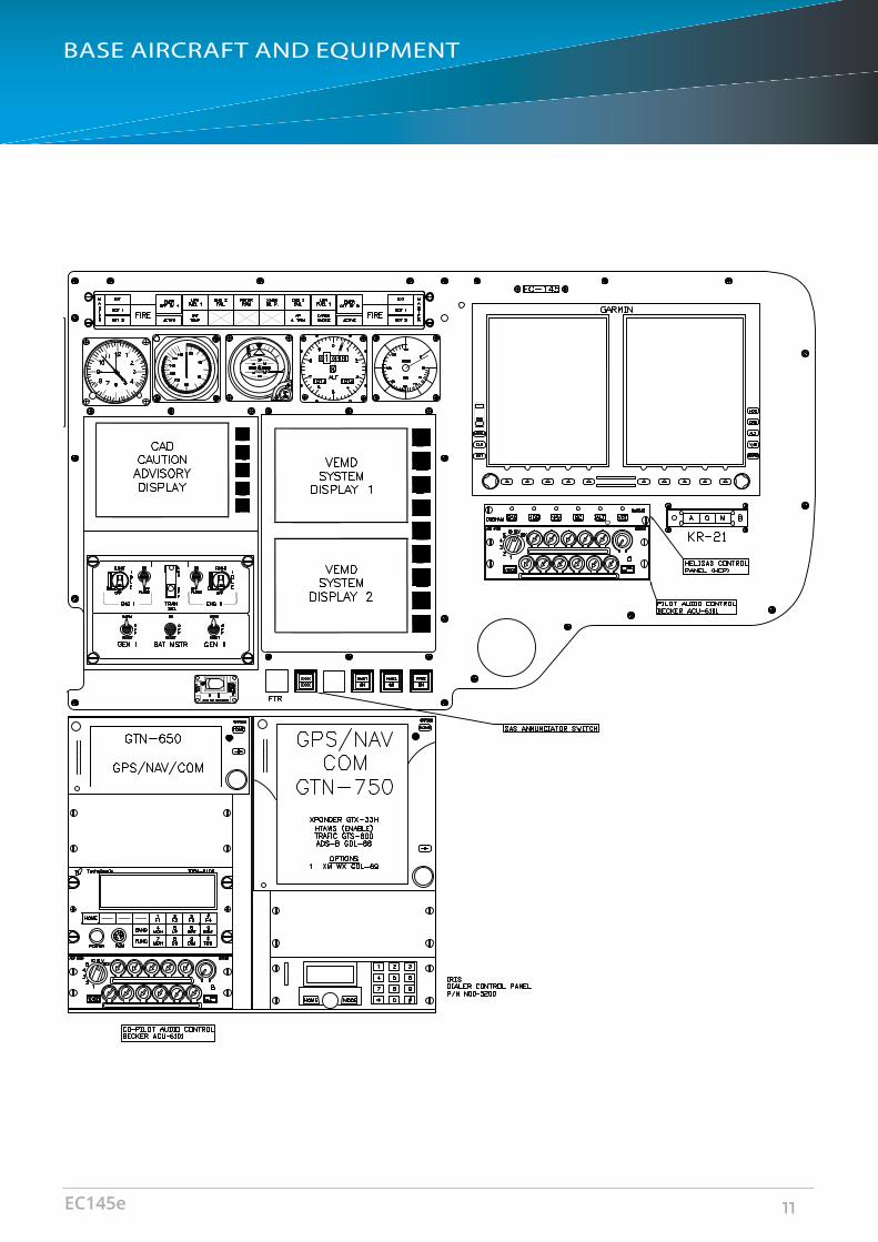
The EC145e includes a single pilot VFR glass cockpit with the Garmin 500H and GTN 650/750 navigation and communication system with 2-axis autopilot. A second configuration for dual pilot VFR includes the Genesys 3D SVS EFIS avionics solution. Single and dual pilot IFR configurations include four Genesys IDU-450 displays that can be configured as a Primary Flight Display (PFD) or a Multi-Function Display (MFD).
• Fully compliant to the latest crash-worthiness requirements FAR29/CS29 – airframe, landing gear and seats
• High set main rotor system• Redundant systems – hydraulic,
electrical and lubrication for the main transmissions
• Reduced DOC with simplified systems
• All Metro STC’s are available
EC145e 3

PASSENGER TRANSPORTConfiguration PILOTS PASSENGERSStandard Seating - High density seating 1/2 9/8 - UP TO 11WEIGHTMaximum takeoff weight 3,585 kg / 7,902 lbsUseful load, baseline aircraft definition 1,810 kg / 3,990 lbs (estimated VFR) ;
1,787 kg / 3,932 lbs (estimated IFR)EMS Equipment, incl. a/c 386 kg / 850 lbsLE Equipment, incl. a/c 506 kg / 1,116 lbsUtility Equipment, incl. a/c 445kg / 981 lbsENGINES (2 TURBOMECA ARRIEL IE2 TURBOSHAFT)Maximum 2.5 min power - one engine inoperative (OEI) 574 kW / 770 shpPERFORMANCE AT 3,300 KG (7,275 LBS), SL, ISAFast Cruising Speed 250 km/h / 135 ktsHover Ceiling IGE 3,840 m / 12,600 ftHover Ceiling OGE 3,45 m / 11,300 ftMaximum range with standard tanks 685 km / 370 NMMaximum endurance at 65 KIAS 3:40hOPERATIONAL LIMITSMaximum operating altitude 5,485 m / 18,000 ft PAMinimum temperature -45 ° C / -49 ° FMaximum temperature ISA + 35 ° C / 95 ° F, limited to +50 ° C / 122 ° F
CONFIGURATION
Metro Aviation4

1 Aircraft Equipment - Factory Installed2 40 AH “SAFT” BATTERY, 24V INSTEAD OF STANDARD BATTERY3 ADDITIONAL ELECTRICAL UNIT4 BLEED AIR HEATING SYSTEM5 CABLE CUTTER SYSTEM, FIXED PROVISIONS6 COPILOT FLIGHT CONTROLS7 COPILOT FLIGHT CONTROLS PEDAL COVER8 COPILOT DOOR SLIDING WINDOW9 ENGINE COMPRESSOR WASH KIT10 EXTERNAL HOIST, LH, MECHANICAL, FIXED PROVISIONS11 EXTERNAL HOIST, RH, MECHANICAL, FIXED PROVISIONS (Must be contracted 12 months in
advance with additional cost)12 FUZZ BURNER FOR ENGINES13 FUZZ BURNER FOR MAIN TRANSMISSION14 FUZZ BURNER FOR TAIL ROTOR AND INTERMEDIATE GEARBOX15 HEIGHT ADJUSTABLE PILOT SEAT INSTEAD OF STANDARD PILOT SEAT16 IMPROVED HEAT PROTECTION FOR ENGINE COWLING LH17 IMPROVED HEAT PROTECTION FOR ENGINE COWLING RH 18 LANDING & SEARCHLIGHT, 400/200 W, FIXED PROVISIONS19 STANDARD COPILOT SEAT20 MAP CASE IN COPILOT DOOR21 PERFORMANCE IMPROVEMENT KIT FOR BLEED AIR HEATING SYSTEM22 TINTED SUNSHADES FOR COCKPIT WINDSHIELD ROOF SECTION23 VECTOR MAST MOMENT SYSTEM (VMMS)24 WINDOW IN CLAMSHELL DOOR - LH25 WINDOW IN CLAMSHELL DOOR - RH26 RIGHT HAND INSTRUMENT PANEL TO BE CUT FOR THE G500H TRAY27 AVIONICS SHELF “PANEL ASSY-AFT DECK RACK / B533K4805-051
BASIC AIRCRAFT AND EQUIPMENT FOR EC145E
Green Aircraft from Factory
1 1 117M-100 AIR CONDITIONING SYSTEM, MECHANICAL DRIVEN, DUAL EVAPORATOR2 1 PAINT 3 COLOR PAINT3 1 PULSE LIGHT4 1 WIRE STRIKE5 1 145M-195 SUPER NIGHT SCANNER
Additional Recommended Items
BASE AIRCRAFT AND EQUIPMENT
EC145e 5

1 1 145M-129 MEDICAL EQUIPMENT MOUNTING, RAILS SYSTEMS AVAILABLE IN AFT WINDOWS, DEPENDING ON PRIMARY MED WALL CONFIG
MAI
2 1 145M-140 PORTABLE OXYGEN MOUNT (MOUNTED ON CLAMSHELL DOOR) MAI3 1 145M-164 CABIN LED FLOOD LIGHTS, BLUE/WHITE HIGH/MED/LOW. ADDITIONAL
PATIENT EXAM LIGHT, STYLE AND LOCATION TO BE DETERMINED. CABIN FLOOD WILL BE OPERATIONAL ON SHORE AND AIRCRAFT POWER
MAI
4 1 145M-167 AFT CABIN LOADING LIGHT MAI5 1 145M-180-1 WHELEN WING TIP STROBES WITH MAI LED ANTI-COLLISION LIGHT MAI6 1 145M-182 SIDE LOADING LIGHTS OVER SLIDING DOORS MAI7 1 145M-183 TAIL FLOOD LIGHTS MAI8 1 145M-185 (2) EA. 250 WATT FIXED REAR CROSS TUBE MOUNTED LIGHTS MAI9 1 145M-250 ALUMINUM MEDICAL FLOOR, NON SKID GRAY POWDER COAT WITH
AVIONICS ACCESS MAI
10 1 145M-250 NYLON BUMPER TO PROTECT END PIECE AT ENTRY OF CLAMSHELL DOORS MAI11 1 145M-*** LITTER / GURNEY SOLUTIONS
LITTER (FERNO 1123, MAI P/N 135M-3000-1)GURNEY (FERNO 28A/28A1, P/S 135M-3500-1)MX PRO GURNEY (STRYKER PRO, MAI P/N 145M-3520-1)PERFORMANCE MANUAL LOAD (STRYKER)
MAI
12 1 145M-410 FIRST AFT FACING TRACKING AND SWIVELING SEAT (COLOR TBD) FISHER13 1 145M-444 SECOND AFT FACING SWIVELING ROTATING SEAT AND TRACKING (COLOR
TBD) FISHER
14 1 145M-444 THIRD FWD/AFT FACING SWIVELING ROTATING SEAT AND TRACKING (COLOR TBD)
FISHER
15 1 145M-444 FOURTH FWD/AFT FACING SWIVELING ROTATING SEAT AND TRACKING (COLOR TBD) (OPTIONAL)
FISHER
16 1 145M-500 MED COMMUNICATION PANEL INSTALL, INCLUDES REMOTE FM AND AUDIO PANELS
MAI
17 1 145M-551 MEDICAL WALL ON PRIMARY SIDE GRID STYLE FOR MOUNTING EQUIPMENT MAI18 1 145M-552 MEDICAL WALL ON RIGHT HAND SIDE, GRID STYLE FOR MOUNTING
EQUIPMENTMAI
19 1 145M-6** STC OXYGEN / LOX SOLUTIONS R/H O2 SYSTEM (145M-610-1)L/H O2 SYSTEM (145M-630-2)EXTERNAL LOX R/H SYSTEM (145M-640-2)
NON-STC LOX (REQUIRES APPROVAL)INTERNAL LOX SYSTEM (145M-650-1)
MAI
20 1 145M-720/730 SUCTION AND AIR SYSTEM WITH OUTLETS EACH, SYSTEM BUILT INTO THE AIRCRAFT
THOMAS
21 1 145M-801 LH ONLY SLANT MEDICAL SWITCH PANEL /RH MEDICAL SWITCH PANEL ONLY NO SLANT
MAI
22 1 145M-810/811 PRIMARY AND SECONDARY IV RAIL HOOKS (6 HOOKS) MAI23 1 145M-900 MEDICAL INVERTER W/ LINE & AUTO SWITCHING. SEPARATE HEATER (HIGH
LOAD) PLUG (15AMP)MAI
24 1 **** MEDICAL EQUIPMENT MOUNTS FOR: (1) CARDIAC MONITOR MOUNT / (1) VENTILATOR MOUNT / (2) INFUSION PUMP MOUNTS
MAI
Full Medical Interior Solution (not compatible with Corporate/VIP Interior Installation)
BASE AIRCRAFT AND EQUIPMENT
Metro Aviation6

1 Corporate Interior to include:2 10 MID GRADE LEATHER UPHOLSTERY COVER - (2) CREW SEATS, (8) CABIN SEATS)3 ** MID GRADE COCKPIT & CABIN CARPET - WITH SURGED SEAMS4 ** PLATING OR REPLACEMENT OF INTERIOR BELT BUCKLES AND AIR NOZZLES AS
APPLICABLE5 ** RE-WEB SEAT BELTS TO MATCH INTERIOR6 ** ADDITIONAL READING LIGHTS7 8 STANDARD MARTIN BAKER SEATS8 1 CUSTOM CABINET9 1 VVIP CUSTOM OPTIONS AVAILABLE
Corporate Interior (not compatible with Medical Interior Solution)
1 8 STANDARD MARTIN BAKER SEATS WITH NAUGAHYDE COVER
2 1 HOIST - REMOVABLE PROVISIONS 3 1 CARGO HOOK4 1 CARGO HOOK MIRRORS 5 1 CARGO NET 6 1 646.4101 DART - TRI-BAG FLOAT SYSTEM WITH OR WITHOUT LIFE RAFT KIT 7 8 EXTERNAL LOUDSPEAKER SYSTEM 8 1 ECMS - FAST ROPING & RAPPELLING
Utility/Offshore Interior (not compatible with Medical Interior Solution)
1 ** CIX-414 xxx CORD ASSEMBLIES COMM INNOVATIONS2 1 RDR-2000 RADAR/ CONTROL PANEL / RADOME BENDIX KING3 1 IRIS FLIGHT FOLLOWING SYSTEM , VOICE, PTT & DATA
MONITORING IRIS
4 1 TA-102 USB SUPPLY FOR COCKPIT EDMO5 1 TDFM 9100 FM VHF/UHF TRANSCEIVER TECHNISONIC6 1 RC-9100NV REMOTE FM CONTROL TECHNISONIC7 1 NVG NVG STC COCKPIT ASU/REB/AD
Optional Avionics Equipment
BASE AIRCRAFT AND EQUIPMENT
EC145e 7

1 4 IDU-450 EFIS SYSTEM CAPABLE OF:• PRIMARY FLIGHT INSTRUMENTS (ATTITUDE, ALTITUDE,
AIRSPEED, AND HEADING)• HSI AND NAVIGATION DISPLAY FOR VOR, ILS, GPS, ADF, ETC.• MOVING MAP• GPS-SBAS FLIGHT MANAGEMENT SYSTEM (FMS) INCLUDING
VNAV, LPV, ETC. (AS LISTED IN RFMS)• HTAWS• SYNTHETIC VISION SYSTEM (SVS)• FLIGHT PATH MARKER• HIGHWAY IN THE SKY
GENESYS
2 1 TAS 605A TRAFFIC WARNING AVIDYNE3 1 KMR 675 MARKER RECEIVER HONEYWELL4 1 GTX 345 ALL-IN-ONE TRANSPONDER SOLUTION FOR ADS-B GARMIN5 2 GNC 255 B NAV/COM TRANSCEIVER GARMIN6 2 ACU-6101 (1) CO-PILOT / (1) PILOT (TOTAL OF [4] AUDIO PANELS IF
MEDICAL COMPLETION)BECKER
7 1 REU-1600 REMOVE ELECTRONIC UNIT BECKER8 1 C406-NHM ELT SYSTEM WITH NAV CAPABILITY ARTEX9 3 LD12-001 ANNUNCIATOR DIMMER EDMO10 3 LD12-IKC LD-12 KIT EDMO11 1 ZFSC-2-1B+ NAV SPLITTER EDMO12 17 LED ****** VIVISUN SWITCHES VIVISUN 13 2 Safe328 COOLING FAN EDMO14 1 CDM - 451 DME CHELTON 15 1 KRA-405B RADAR ALTIMETER HONEYWELL16 1 HOT MIKE IN CLAMSHELL DOOR AREA MAI17 1 RADIO MASTER MAI18 1 HELISAS 3 AXIS HELISAS SP/DPIFR GENESYS
Genesys IFR Avionics Equipment
BASE AIRCRAFT AND EQUIPMENT
Metro Aviation8

BASE AIRCRAFT AND EQUIPMENT
EC145e 9

1 1 GTN 750 GPS/COM GARMIN2 1 010-00878-02 HTAWS ENABLEMENT CARD GARMIN 3 1 GTN 650 GPS/COM GARMIN4 1 GTX-345R ALL-IN-ONE TRANSPONDER SOLUTION FOR ADS-B "OUT" AND
"IN"GARMIN
5 1 GDL 69HSXM
XM WEATHER GARMIN
6 1 GTS 800 TRAFFIC WARNING (OPTIONAL) GARMIN7 1 KR-21 MARKER RECEIVER HONEYWELL8 2 ACU-6101 (1) CO-PILOT / (2) REAR CABIN AUDIO PANELS (TOTAL OF (4)
AUDIO PANELS IF MEDICAL COMPLETION)BECKER
9 1 REU-6100 REMOTE ELECTRONIC UNIT BECKER10 1 C406-NHM ELT SYSTEM WITH NAV CAPABILITY ARTEX11 1 G500H EFIS DISPLAY GARMIN 12 1 804 ** STANDBY GYRO 13 1 KRA-405B RADAR ALTIMETER HONEYWELL14 1 RADAR ENABLEMENT CARD GARMIN 15 1 HOT MIKE IN CLAMSHELL DOOR AREA MAI16 1 RADIO MASTER MAI17 1 Helisas 2 AXIS HELISAS VFR GENESYS
Garmin VFR Avionics Equipment
BASE AIRCRAFT AND EQUIPMENT
Metro Aviation10
BASE AIRCRAFT AND EQUIPMENT
EC145e 11
AIR MEDICAL
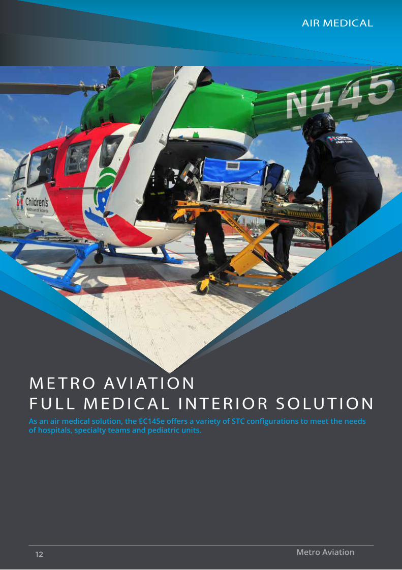
M E T R O AV I AT I O N F U L L M E D I C A L I N T E R I O R S O LU T I O NAs an air medical solution, the EC145e offers a variety of STC configurations to meet the needs of hospitals, specialty teams and pediatric units.
Metro Aviation12

AIR MEDICAL
EMS PRIMARY SEATING AND PATIENT ARRANGEMENTSThis arrangement includes three (3) Seats and a LH patient:
• The forward cabin LH and RH Aft-Facing Track & Swivel seats
• The aft cabin RH Fwd-Facing Track & Swivel seats position for Taxi, Take-Off and Landing. Can be moved forward when 2 patients loaded.
• The LH PATIENT litter/gurney at STA 4522 will be locked into position for Taxi, Take-Off and Landing
SEATING
EC145e 13
AIR MEDICAL
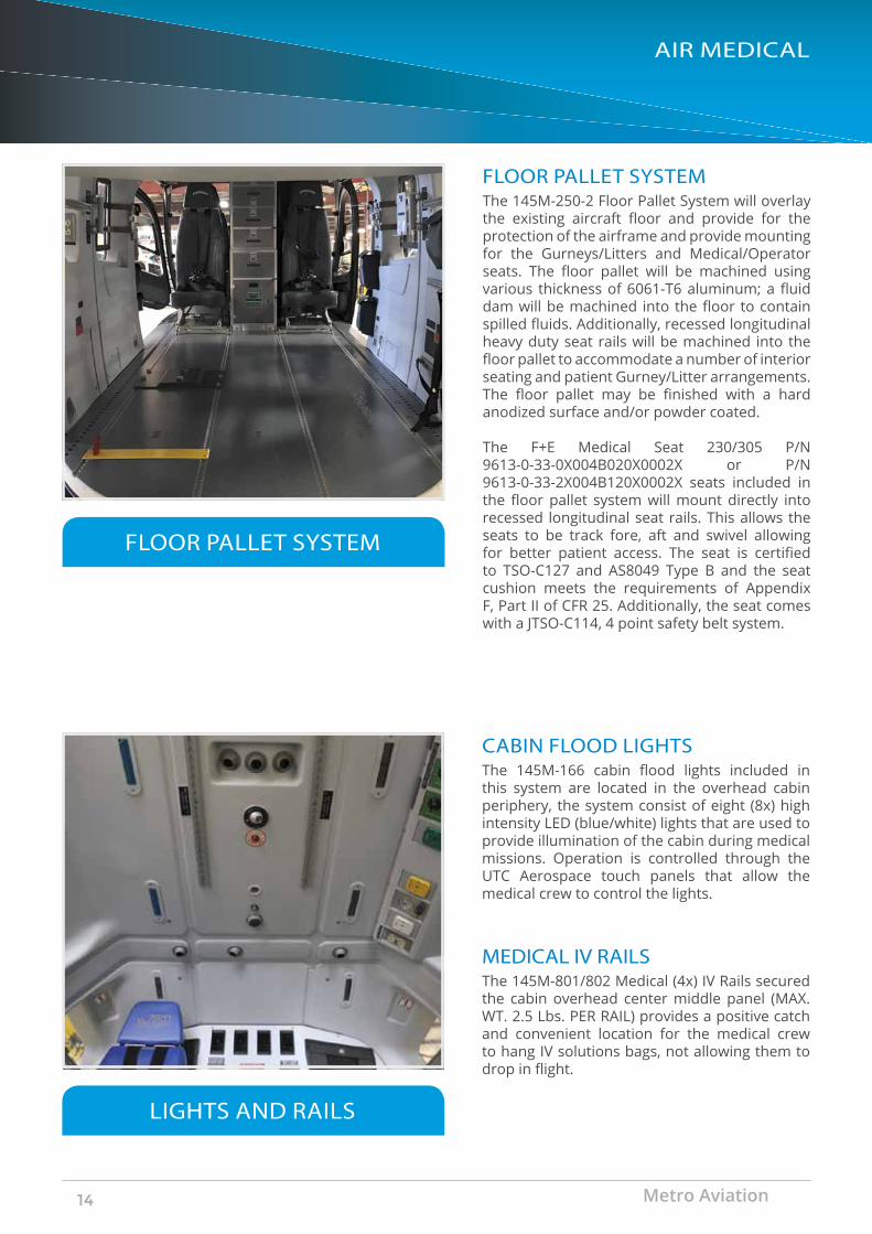
FLOOR PALLET SYSTEMThe 145M-250-2 Floor Pallet System will overlay the existing aircraft floor and provide for the protection of the airframe and provide mounting for the Gurneys/Litters and Medical/Operator seats. The floor pallet will be machined using various thickness of 6061-T6 aluminum; a fluid dam will be machined into the floor to contain spilled fluids. Additionally, recessed longitudinal heavy duty seat rails will be machined into the floor pallet to accommodate a number of interior seating and patient Gurney/Litter arrangements.The floor pallet may be finished with a hard anodized surface and/or powder coated.
The F+E Medical Seat 230/305 P/N 9613-0-33-0X004B020X0002X or P/N 9613-0-33-2X004B120X0002X seats included in the floor pallet system will mount directly into recessed longitudinal seat rails. This allows the seats to be track fore, aft and swivel allowing for better patient access. The seat is certified to TSO-C127 and AS8049 Type B and the seat cushion meets the requirements of Appendix F, Part II of CFR 25. Additionally, the seat comes with a JTSO-C114, 4 point safety belt system.
FLOOR PALLET SYSTEM
CABIN FLOOD LIGHTSThe 145M-166 cabin flood lights included in this system are located in the overhead cabin periphery, the system consist of eight (8x) high intensity LED (blue/white) lights that are used to provide illumination of the cabin during medical missions. Operation is controlled through the UTC Aerospace touch panels that allow the medical crew to control the lights.
LIGHTS AND RAILS
MEDICAL IV RAILSThe 145M-801/802 Medical (4x) IV Rails secured the cabin overhead center middle panel (MAX. WT. 2.5 Lbs. PER RAIL) provides a positive catch and convenient location for the medical crew to hang IV solutions bags, not allowing them to drop in flight.
Metro Aviation14

AIR MEDICAL
GASEOUS CONTINUOUS FLOW OXYGEN SYSTEMThe Emergency Medical System KIT 145M-100-3 Optional Continuous Flow Oxygen System includes a primary right hand cylinder system. The optional 145M-610-3 RH Oxygen System consists of a:
• Cirrus/Metro Style Cylinder-Valve Assembly (approx. 77.1 cu ft/2700 liters)
• Digital Indicator • Shut-off valve • Pressure transmitter • Pressure switch • Cabin emergency shutoff switch• Pilot cutoff switch • Cabin oxygen outlets
The right hand Cylinder-Valve Assembly (77.1 cu ft) is mounted to the fuselage between the cross tubes below the door tracks on the right hand outboard side and covered by a fiberglass fairing. Low-pressure oxygen is supplied to the cabin though 1/4” seamless stainless steel lines. The low-pressure system can be cut off at the point where it enters the aircraft by an electrically controlled shut off valve. There is an emergency shut-off switch in the system. The shut-off valve is controlled by three switch system: a pilot master cutoff switch, an emergency oxygen override switch in the cabin if touch screens fails. Cabin touch screens are for the normal on/off operation used by the medical crew. The touch screens also have annunciation of low oxygen pressure below 40–45 psi. The contents of the bottle can be monitored on a digital gauge in the cabin. Servicing of the Cylinder-Valve Assembly (77.1 cu ft) will be through a fill port located adjacent to the right hand Oxygen cylinder.
Optional secondary 145M-630 LH Oxygen System is available.
OXYGEN SYSTEM
EC145e 15
AIR MEDICAL
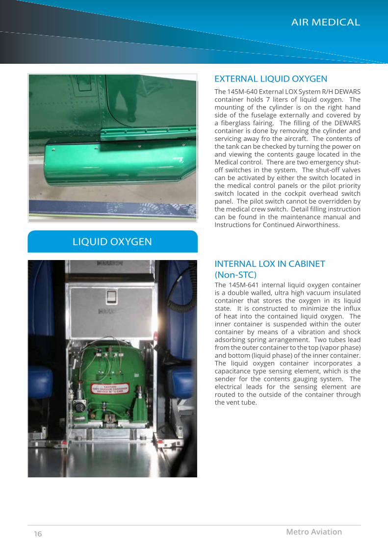
EXTERNAL LIQUID OXYGENThe 145M-640 External LOX System R/H DEWARS container holds 7 liters of liquid oxygen. The mounting of the cylinder is on the right hand side of the fuselage externally and covered by a fiberglass fairing. The filling of the DEWARS container is done by removing the cylinder and servicing away fro the aircraft. The contents of the tank can be checked by turning the power on and viewing the contents gauge located in the Medical control. There are two emergency shut-off switches in the system. The shut-off valves can be activated by either the switch located in the medical control panels or the pilot priority switch located in the cockpit overhead switch panel. The pilot switch cannot be overridden by the medical crew switch. Detail filling instruction can be found in the maintenance manual and Instructions for Continued Airworthiness.
LIQUID OXYGEN
INTERNAL LOX IN CABINET (Non-STC)The 145M-641 internal liquid oxygen container is a double walled, ultra high vacuum insulated container that stores the oxygen in its liquid state. It is constructed to minimize the influx of heat into the contained liquid oxygen. The inner container is suspended within the outer container by means of a vibration and shock adsorbing spring arrangement. Two tubes lead from the outer container to the top (vapor phase) and bottom (liquid phase) of the inner container. The liquid oxygen container incorporates a capacitance type sensing element, which is the sender for the contents gauging system. The electrical leads for the sensing element are routed to the outside of the container through the vent tube.
Metro Aviation16

AIR MEDICAL
MEDICAL SUCTION SYSTEM
MEDICAL AIR SYSTEM
The optional 145M-720-3 Medical Suction System provides a suction source for various medical carry on equipment used by the medical crew in the care of patients. The Medical Suction System consists of a suction pump, suction outlets and a regulator. Operation is controlled by the UTC Aerospace Control System touch panels, located in the cabin. This installation contains electrical wires/cables that run to and from equipment that interface with the medical suction system. The medical suction system plumbing contains tubing that run to and from the suction pump, suction outlets and a regulator located in the cabin.Layout of panel is customizable by customer
The optional 145M-730 Medical Air System provides an air source for various medical carry on equipment used by the medical crew in the care of patients. The Medical Air System consists of a medical air pump and air outlets. Low pressure annunciated on the touch screens when below 40–45 psi. The pump’s air is regulated and filtered. This installation contains electrical wires/cables that run to and from equipment that interface with the medical air system. The medical air system plumbing contains tubing that run to and from the air pump and two air outlets located in the medical slant panel.
OPTIONAL OUTLET LOCATIONSPRIMARY MEDICAL SLANT PANELThe 145M-801 Medical Slant Panel is located above the large aft cabin windows. The panel provides mounting locations for the oxygen/suction regulators and outlets, and other lights and installed equipment.
The left panel is standard. An optional right hand panel is available.
EC145e 17
AIR MEDICAL
MEDICAL CONTROL PANEL
PORTABLE OXYGEN MOUNT
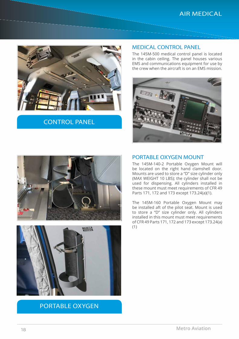
The 145M-500 medical control panel is located in the cabin ceiling. The panel houses various EMS and communications equipment for use by the crew when the aircraft is on an EMS mission.
The 145M-140-2 Portable Oxygen Mount will be located on the right hand clamshell door. Mounts are used to store a “D” size cylinder only (MAX WEIGHT 10 LBS); the cylinder shall not be used for dispensing. All cylinders installed in these mount must meet requirements of CFR 49 Parts 171, 172 and 173 except 173.24(a)(1).
The 145M-160 Portable Oxygen Mount may be installed aft of the pilot seat. Mount is used to store a “D” size cylinder only. All cylinders installed in this mount must meet requirementsof CFR 49 Parts 171, 172 and 173 except 173.24(a)(1)
CONTROL PANEL
PORTABLE OXYGEN
Metro Aviation18

FERNO 28A1
AIR MEDICAL
MODIFIED STRYKER MX PRO R3 FERNO WASHINGTON MODEL 28A
STRYKER GURNEY FERNO 28
This 145M-352 MX PRO Gurney is an alternate for primary 145M-350 gurney, it consist of a modified Stryker MX PRO R3. The Gurney is modified by the addition of the Metro Aviation posi-lock latching mechanism consisting of a receiver and latch mechanism attached to the gurney assembly and a plate with alignment and securing studs attached to the cabin seat rails.
The belt system is system attached directly to the Gurney. The Gurney is rolled through the aft cabin clamshell doors and self aligns with the plate. Once fully seated home a restraint pin deploys automatically restraining the Gurney in place until a handle on the foot end of the Gurney is actuated and the Gurney is rolled aft.
The 145M-350 was designed by the manufacturer for installation in aircraft application. The Gurney is modified by the addition of the Metro Aviation posi-lock latching mechanism consisting of a receiver and latch mechanism attached to the gurney assembly and a plate with alignment and securing studs attached to the cabin seat rails.
The new Stryker performance manual load is available.
EC145e 19
AIR MEDICAL
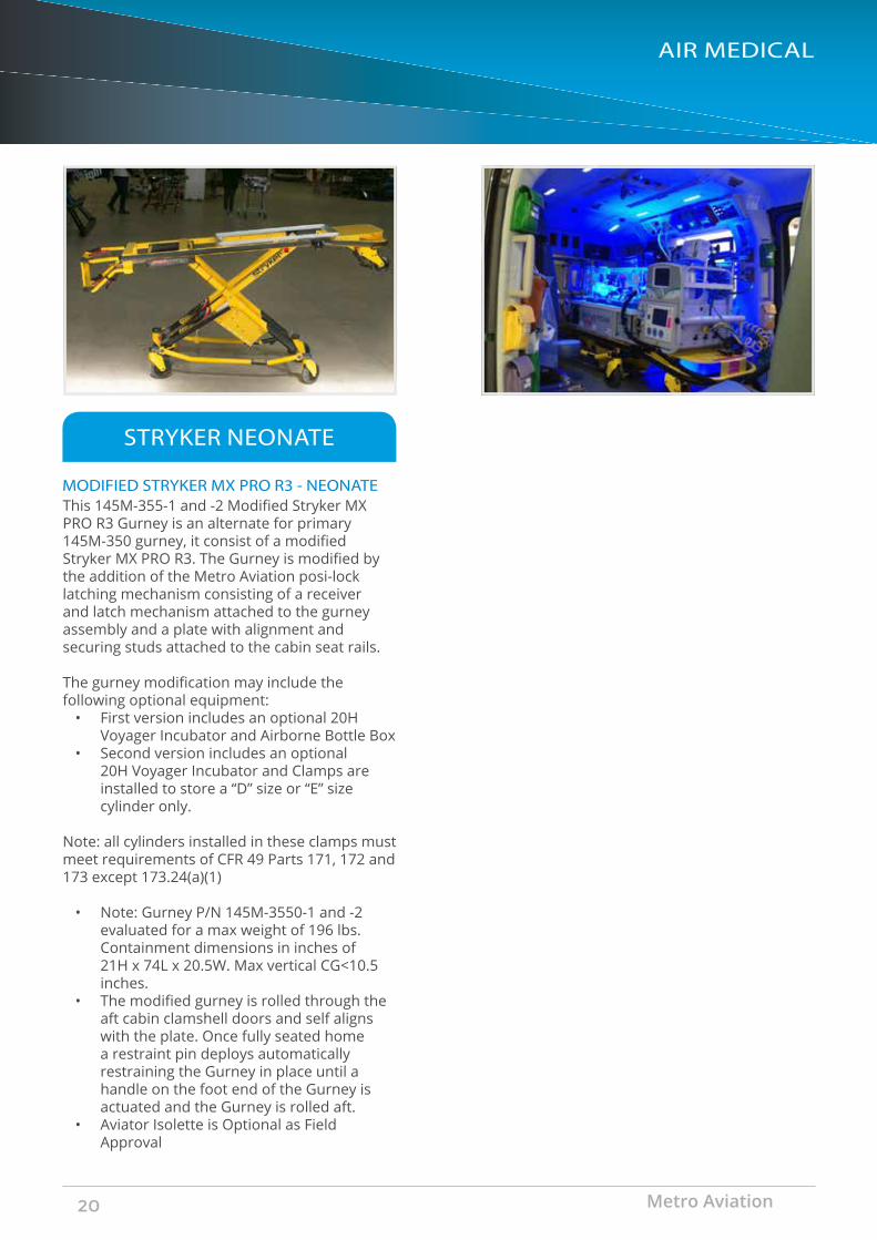
MODIFIED STRYKER MX PRO R3 - NEONATE
STRYKER NEONATE
This 145M-355-1 and -2 Modified Stryker MX PRO R3 Gurney is an alternate for primary 145M-350 gurney, it consist of a modified Stryker MX PRO R3. The Gurney is modified by the addition of the Metro Aviation posi-lock latching mechanism consisting of a receiver and latch mechanism attached to the gurney assembly and a plate with alignment and securing studs attached to the cabin seat rails.
The gurney modification may include the following optional equipment:
• First version includes an optional 20H Voyager Incubator and Airborne Bottle Box
• Second version includes an optional 20H Voyager Incubator and Clamps are installed to store a “D” size or “E” size cylinder only.
Note: all cylinders installed in these clamps must meet requirements of CFR 49 Parts 171, 172 and 173 except 173.24(a)(1)
• Note: Gurney P/N 145M-3550-1 and -2 evaluated for a max weight of 196 lbs. Containment dimensions in inches of 21H x 74L x 20.5W. Max vertical CG<10.5 inches.
• The modified gurney is rolled through the aft cabin clamshell doors and self aligns with the plate. Once fully seated home a restraint pin deploys automatically restraining the Gurney in place until a handle on the foot end of the Gurney is actuated and the Gurney is rolled aft.
• Aviator Isolette is Optional as Field Approval
Metro Aviation20
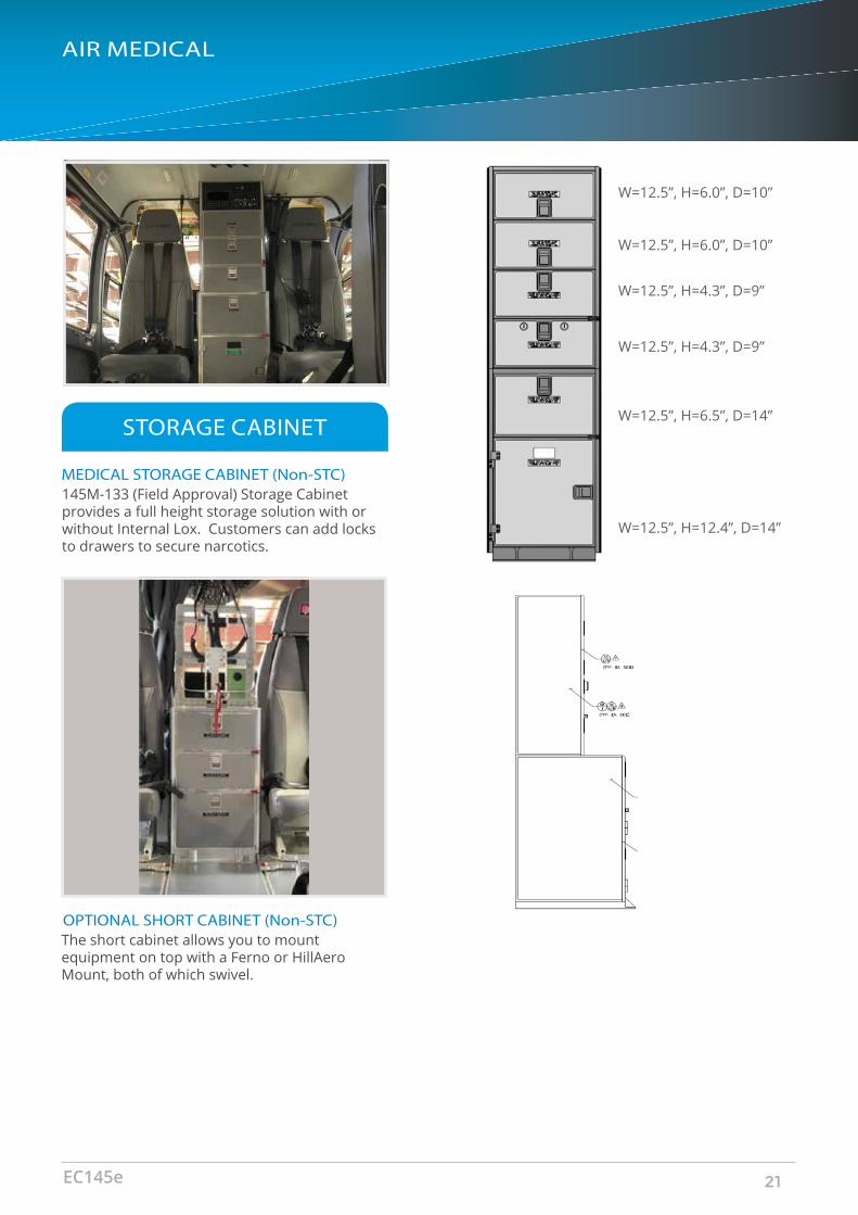
W=12.5”, H=6.0”, D=10”
W=12.5”, H=6.0”, D=10”
W=12.5”, H=4.3”, D=9”
W=12.5”, H=4.3”, D=9”
W=12.5”, H=6.5”, D=14”
W=12.5”, H=12.4”, D=14”
AIR MEDICAL
MEDICAL STORAGE CABINET (Non-STC)
STORAGE CABINET
145M-133 (Field Approval) Storage Cabinet provides a full height storage solution with or without Internal Lox. Customers can add locks to drawers to secure narcotics.
OPTIONAL SHORT CABINET (Non-STC)The short cabinet allows you to mount equipment on top with a Ferno or HillAero Mount, both of which swivel.
EC145e 21
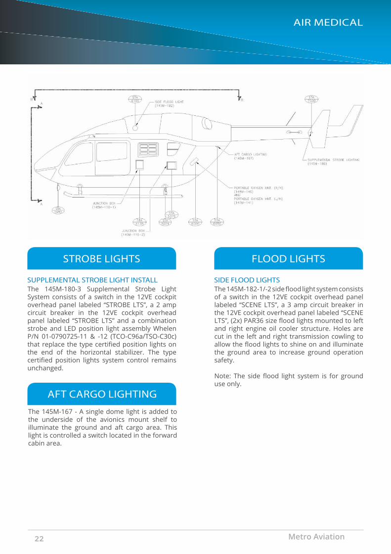
SUPPLEMENTAL STROBE LIGHT INSTALL
STROBE LIGHTS
The 145M-180-3 Supplemental Strobe Light System consists of a switch in the 12VE cockpit overhead panel labeled “STROBE LTS”, a 2 amp circuit breaker in the 12VE cockpit overhead panel labeled “STROBE LTS” and a combination strobe and LED position light assembly Whelen P/N 01-0790725-11 & -12 (TCO-C96a/TSO-C30c) that replace the type certified position lights on the end of the horizontal stabilizer. The type certified position lights system control remains unchanged.
SIDE FLOOD LIGHTS
FLOOD LIGHTS
The 145M-182-1/-2 side flood light system consists of a switch in the 12VE cockpit overhead panel labeled “SCENE LTS”, a 3 amp circuit breaker in the 12VE cockpit overhead panel labeled “SCENE LTS”, (2x) PAR36 size flood lights mounted to left and right engine oil cooler structure. Holes are cut in the left and right transmission cowling to allow the flood lights to shine on and illuminate the ground area to increase ground operation safety.
Note: The side flood light system is for ground use only.
AIR MEDICAL
AFT CARGO LIGHTING
The 145M-167 - A single dome light is added to the underside of the avionics mount shelf to illuminate the ground and aft cargo area. This light is controlled a switch located in the forward cabin area.
Metro Aviation22

AIR MEDICAL
AUXILIARY LIGHTING
TAIL FLOOD LIGHT
CONTROLLABLE SEARCH LIGHT
TAIL FLOOD LIGHT
LANDING SEARCHLIGHT
The 145M-195-3 Controllable searchlight system consists of a 850,000 candle power search light and collective mounted switches (existing) for on-off, stow and azimuth and elevation control. The search light is powered by a 25 amp CB labeled “LDG LGT PWR” on Shed Bus 1 in the left hand service connector 11VE panel and a 2 amp CB labeled “NSCAN” located in the cockpit overhead 12VE panel. The controllable search light is mounted in forward belly (chin panel) and is operated by the activation of the collective mounted switches. There are two switches, one toggle switch for on and off and stow located in the cockpit overhead 12VE panel. One “Chinese hat” switch for elevation and azimuth control located in the pilot’s collective. This allows the pilot to better perform reconnaissance of a landing area at night.
The 145M-183-3 tail flood light system consists of a switch in the 12VE cockpit overhead panel labeled “TAIL LT”, a 2 amp circuit breaker in the 12VE cockpit overhead panel labeled “TAIL LT”, a single PAR36 size flood light in a housing mounted on the aft engine cowls and a load light located on the bottom of the tail boom. The tail light illuminates the tail rotor area and the load light on the bottom of the tail boom illuminates the ground area providing increased safety during ground operations. Note: The tail flood/load light system is for ground use only.
The 145M-185-3 auxiliary lighting system consists of (2x) PAR46 lights secured to the aft cross tube below the belly of the aircraft, a 35 Amp Fuse located in the Aft Battery Box 3VE , and a relay. To activate the lights use the pilot’s collective mounted on-off switch labeled “AUX LTS”.
EC145e 23
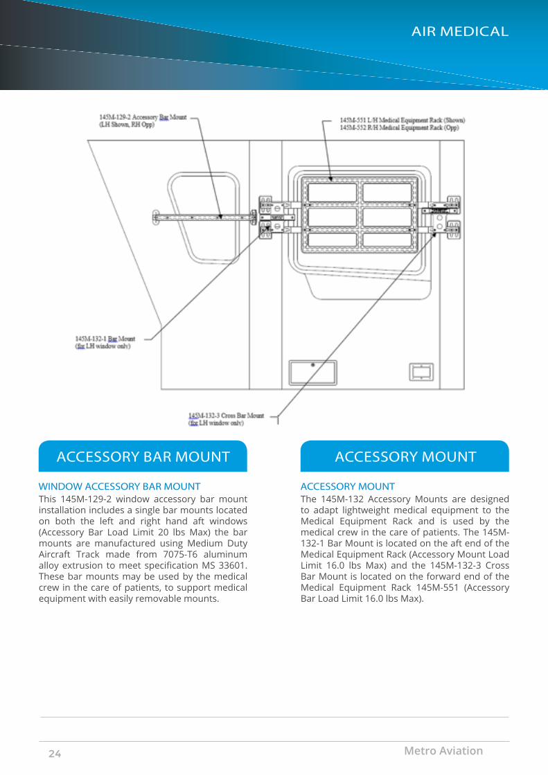
WINDOW ACCESSORY BAR MOUNT
ACCESSORY BAR MOUNT
This 145M-129-2 window accessory bar mount installation includes a single bar mounts located on both the left and right hand aft windows (Accessory Bar Load Limit 20 lbs Max) the bar mounts are manufactured using Medium Duty Aircraft Track made from 7075-T6 aluminum alloy extrusion to meet specification MS 33601. These bar mounts may be used by the medical crew in the care of patients, to support medical equipment with easily removable mounts.
ACCESSORY MOUNT
ACCESSORY MOUNT
The 145M-132 Accessory Mounts are designed to adapt lightweight medical equipment to the Medical Equipment Rack and is used by the medical crew in the care of patients. The 145M-132-1 Bar Mount is located on the aft end of the Medical Equipment Rack (Accessory Mount Load Limit 16.0 lbs Max) and the 145M-132-3 Cross Bar Mount is located on the forward end of the Medical Equipment Rack 145M-551 (Accessory Bar Load Limit 16.0 lbs Max).
AIR MEDICAL
Metro Aviation24
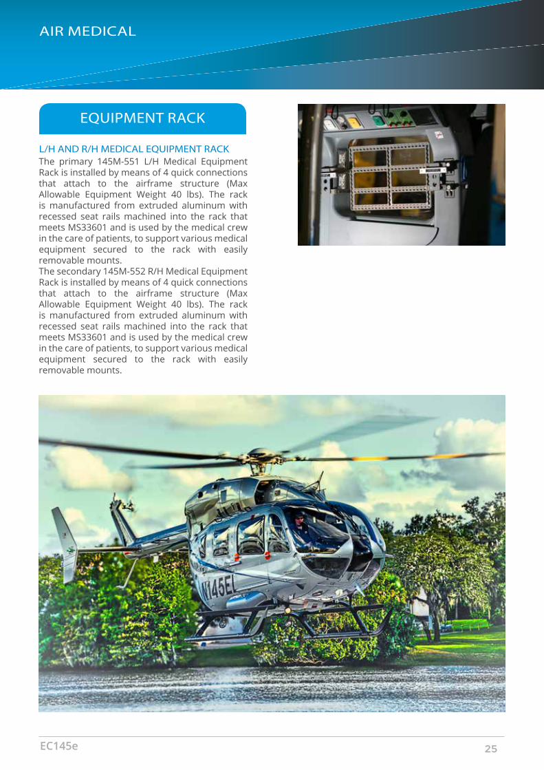
L/H AND R/H MEDICAL EQUIPMENT RACK
EQUIPMENT RACK
The primary 145M-551 L/H Medical Equipment Rack is installed by means of 4 quick connections that attach to the airframe structure (Max Allowable Equipment Weight 40 lbs). The rack is manufactured from extruded aluminum with recessed seat rails machined into the rack that meets MS33601 and is used by the medical crew in the care of patients, to support various medical equipment secured to the rack with easily removable mounts. The secondary 145M-552 R/H Medical Equipment Rack is installed by means of 4 quick connections that attach to the airframe structure (Max Allowable Equipment Weight 40 lbs). The rack is manufactured from extruded aluminum with recessed seat rails machined into the rack that meets MS33601 and is used by the medical crew in the care of patients, to support various medical equipment secured to the rack with easily removable mounts.
AIR MEDICAL
EC145e 25

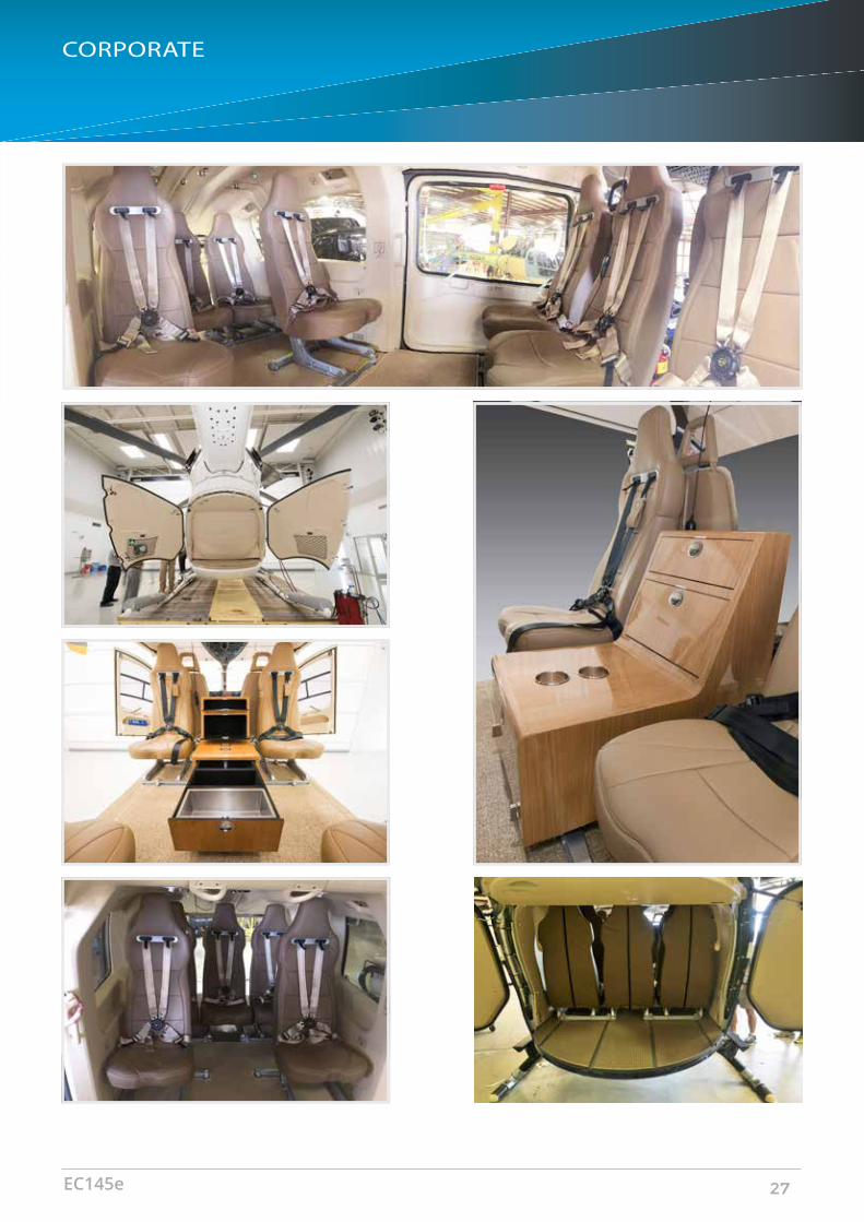
CORPORATE
M E T R O AV I AT I O N C O R P O R AT E I N T E R I O R S O LU T I O N
Metro Aviation26
CORPORATE
EC145e 27

UTILITY
M E T R O AV I AT I O N U T I L I T Y C O N F I G U R AT I O N
Metro Aviation28
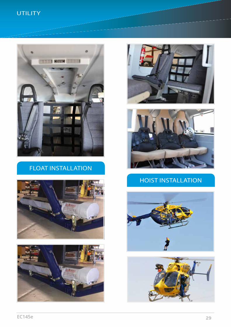
FLOAT INSTALLATION
HOIST INSTALLATION
UTILITY
EC145e 29
• 9,500sf avionics
• 23,100sf production
• 5,800sf CNC machine shop
• 7,200sf engine & accessory overhaul
• 35,000sf completions and maintenance hangar
• 11,500sf paint shop
• 10,000sf inventory
• 38,500sf training center
• 17,200sf administrative offices
• 2,200sf Outerlink Headquarters
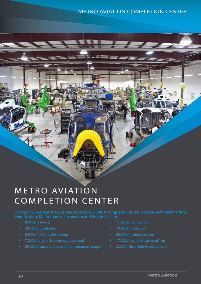
Located in Shreveport, Louisiana, Metro’s 160,000 sf completion center is a FAA Certified Airframe Modification, Maintenance, Inspection and Repair Facility.
• 9,500sf avionics
• 23,100sf production
• 5,800sf CNC machine shop
• 7,200sf engine & accessory overhaul
• 35,000sf completions and maintenance hangar
• 11,500sf paint shop
• 10,000sf inventory
• 38,500sf training center
• 17,200sf administrative offices
• 2,200sf Outerlink Headquarters
METRO AVIATION COMPLETION CENTER
M E T R O AV I AT I O N C O M P L E T I O N C E N T E R
Metro Aviation30

• 9,500sf avionics
• 23,100sf production
• 5,800sf CNC machine shop
• 7,200sf engine & accessory overhaul
• 35,000sf completions and maintenance hangar
• 11,500sf paint shop
• 10,000sf inventory
• 38,500sf training center
• 17,200sf administrative offices
• 2,200sf Outerlink Headquarters
Metro’s aircraft completions center is a full service facility capable of a complete range of modification and upgrade packages for new and existing customers. Metro has extensive experience in air medical, law enforcement, offshore, utility, VIP and corporate aircraft.
Metro’s highly trained and dedicated staff is available during the entire completion process as we build your new aircraft to your precise specifications. The Aircraft Configuration Coordinator is in constant communication with customers every step of the way. From the production design review to your on-site tour and paint design, Metro is a trusted partner to ensure the aircraft is completed to the specifications outlined in the scope of work and all new modifications suggested by the customer are tested and approved to the highest standard.
Metro has completed more EC135s and EC145s than any other completion center in the world and our more than 30 STC’s (Supplemental Type Certificates) include EMS and avionics, and they cover the AS350, BO105, BK117, EC130, EC135, EC145, Bell 407 and the first STC for an air medical completion of the EC155 in the world. Metro Aviation was the first company in the U.S. to achieve Level IV of the FAA’s SMS Pilot Project for a Part 145 Repair Station.
METRO AVIATION COMPLETION CENTER
EC145e 31