Embed Size (px)
Citation preview
Part #ECSPEC rev 1-31-14 1
PIXEL ELEVATOR CONTROL SYSTEM
Technical Product Specifications
Simple. Solid. Supportable.

Table of Contents Part #ECSPEC rev 1-31-14 2
Table of Content
Technical Product Specifications
Section i Pixel System Overview 3
Section ii Typical System Components 5
Section iii Easier, Faster, Better 7
Section iv About Elevator Controls 12
Section v How to Use These Specifications 13
Section vi Warranty & Support 16
Section 1 Pixel General Specifications 18
Section 2 AC Traction Elevator Controls 24
Section 3 DC Traction Elevator Controls 33
Section 4 Hydraulic Elevator Controls 42
Section 5 Dispatching Functionality 49
Section 6 Motors & Machines 56
Section 7 Optional Features 57
Section 8 Landing System 62
Section 9 Load Weighing 64
Section 10 Interact TM Central Monitoring 66
Section 11 Security 73
Section 12 Physical Specifications 77

i – Pixel System Overview Part #ECSPEC rev 01-31-14 3
i Pixel System Overview The Pixel Traction Control System uses advanced tec hnology to enable more routine tasks to be accomplished fas ter. Everything about Pixel has been designed to save fi eld labor time . For example, this digital elevator control system provides three points of system access – Machine Room, Cartop, and Inside the Cab – so the most convenient location can be used to complete tasks quickly and easily. Each of the three system access points includes a vivid color LCD display, unique Touch & GoTM interface, one-button access to context-responsive help, and intuitive direct-select keys. Instant real-time awareness of current car operation is provided on the home screen. Landa TM car positioning system is actually two independent systems that provide position information with accuracy to 0.032” (0.8mm). Dual communication channels, one for each positioning system, provide truly independent redundancy for failsafe operation. Landa components are mounted quickly –then all limits, slowdowns and landings are defined virtually, stored digitally, and easily readjusted. No hoistway wiring, vanes or switches are used (except top and bottom physical limit switches as required by code). Powerful yet simplified diagnostics are built into each system access point, including the ability to intuitively view and easily reprogram elevator “personality” parameters onsite. Capabilities include review and adjustment of drive parameters, access to fault diagnostics, and playback of the operating sequence that proceeded a fault notification. The integrated Pixel control system package typically includes the car controller, cartop box with access point, COP access point, Landa positioning system, and hall nodes that communicate using EC’s enhanced c-LINK TM. This CAN-bus serial communication system reduces wire count for hall, car and cartop signals without compromising EC’s Safe & SensibleTM standards. Dual CAN-bus controller area networks provide high speed internal system communication. Use of this industrial standard communication protocol opens the door to interoperability with a variety of current and future products and peripherals – including the latest door operators.

i – Pixel System Overview Part #ECSPEC rev 01-31-14 4
Overall system reliability is enhanced through the use of surface-mount electronic components, large scale integrated circuits, and state-of-the-art PC boards. When the power of technology is used to simplify essential tasks – including installation, adjustment, maintenance and troubleshooting – everybody wins. Pixel Traction Series Capabilities
Speed 1400 fpm | 7 mps
Stops 128 Stops maximum with selective door operation
Group Size 12 cars maximum
Environment 32 to 104 degrees Fahrenheit | 0C to 40C degrees Altitude to 12,000 feet | 3,658 meters 95% relative humidity (non-condensing)
Motor Control
AC induction or permanent magnet hoist motor Variable voltage variable frequency VVVF elevator drive with encoder feedback
DC hoist motor SCR or IGBT elevator drive with encoder feedback
Positioning Landa™ absolute car positioning system using dual non-contact sensor heads to provide position information to 0.032” (0.8mm)
Pixel Hydraulic Series Capabilities
Speed 300 fpm | 1.5 mps
Stops 128 Stops maximum with selective door operation
Group Size 12 cars maximum
Environment 32 to 104 degrees Fahrenheit | 0C to 40C degrees Altitude to 12,000 feet | 3,658 meters 95% relative humidity (non-condensing)
Motor Control
Solid State Starter Y-Delta Mechanical Starter Across the line, Delta, Mechanical Starter
Positioning Landa™ absolute car positioning system using dual sensor heads and coated tape to track position accuracy to 0.032” (0.8mm)

ii – Pixel Typical System Components Part #ECSPEC rev 01-31-14 5 I5
ii Typical System Components The most basic Pixel component, a car controller, i ncorporates intelligent subsystems. Pixel’s system design supports group operation for up to twelve cars using a dual high speed CAN-bus controller area network communications architecture.
a. Pixel Car controller
b. P-TOC Pixel top of the car interface controller
c. P-COP Pixel car operation panel interface controller (one per COP; up to four per car supported)
d. P-HALL Pixel hall nodes (as required for hall calls, fire recall, gongs, etc)
e. Landa™ dual sensor car positioning system
System Components At a Glance The Pixel control system – depending on the specific application – typically includes:
a. Pixel Car Controller
The Pixel car controller is usually located in a machine room or – in machine-room-less applications, in an equipment closet. Various enclosures are available to fit your specific application… and meet your NEMA rating requirements.
b. P-TOC Pixel Cartop Interface The cartop system access point provides access to configuration information, parameters and diagnostics. The cartop interface box provides a convenient wiring termination for Landa, door operator, load weigher, safety edge, cab light and fan, traveler cable and the provided TOC-to-COP wire harness. Optional (similar to photo) cartop Inspection station with light and service outlet is available.

ii – Pixel Typical System Components Part #ECSPEC rev 01-31-14 6 I6
c. P-COP Pixel Car Operating Panel Interface A system access point is located at each COP. EC-Ready COP Fixtures fully interconnect to the TOC box using the provided TOC-to-COP harness. One wiring harness is provided for each of up to four COP’s per cab.
d. P-HALL Pixel Hall Nodes Universal hall nodes can provide connections for hall calls, fire recall, access, hall gongs, code blue calls and more. Each CAN-driven node supports two I/O easily configurable using onboard switchgear.
e. Landa™ Dual Positioning System Landa is a dual positioning system that provides absolute cab location information without the need for vanes or switches in the hoistway.* Dual communication channels, one for each positioning system, provide truly independent redundancy for failsafe operation. Landa provides precision accuracy – tracking cab location with accuracy to 0.032” (0.8mm).
* Top and bottom physical limit switches
must be provided as required by elevator safety code.
iii – Easier, Faster, More Efficient Part #ECSPEC rev 01-31-14 7
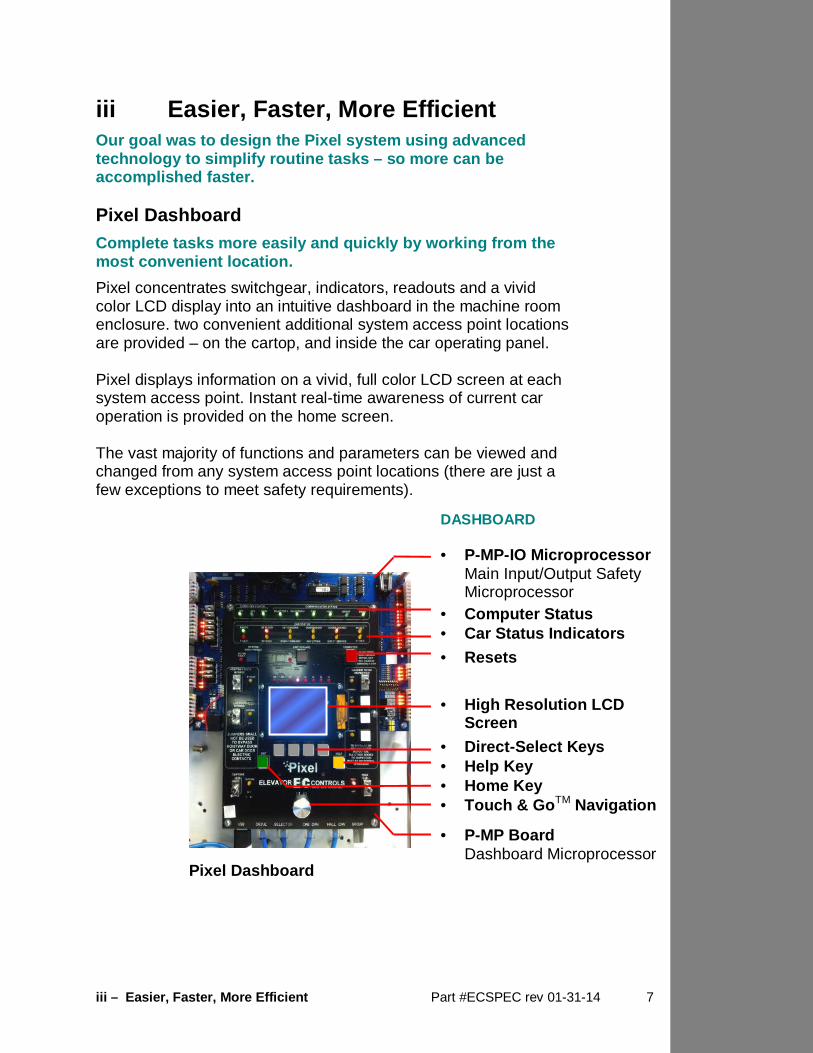
iii Easier, Faster, More Efficient Our goal was to design the Pixel system using advan ced technology to simplify routine tasks – so more can be accomplished faster. Pixel Dashboard Complete tasks more easily and quickly by working f rom the most convenient location.
Pixel concentrates switchgear, indicators, readouts and a vivid color LCD display into an intuitive dashboard in the machine room enclosure. two convenient additional system access point locations are provided – on the cartop, and inside the car operating panel. Pixel displays information on a vivid, full color LCD screen at each system access point. Instant real-time awareness of current car operation is provided on the home screen. The vast majority of functions and parameters can be viewed and changed from any system access point locations (there are just a few exceptions to meet safety requirements).
Pixel Dashboard
DASHBOARD • P-MP-IO Microprocessor Main Input/Output Safety Microprocessor
• Computer Status • Car Status Indicators
• Resets • High Resolution LCD
Screen
• Direct-Select Keys • Help Key • Home Key • Touch & Go TM Navigation
• P-MP Board Dashboard Microprocessor

iii – Easier, Faster, More Efficient Part #ECSPEC rev 01-31-14 8
Pixel Screen and Navigation
Pixel uses a simple knob for navigation and selecti on – called ‘Touch and Go TM’ – so everything needed is at your fingertips.
Pixel’s high resolution color LCD screen is paired with a simple, intuitive selection knob called the Touch & GoTM interface. Rotate to scroll up and down any selection list. Then – press this same knob – to select the desired function (or setting) and keep right on working.
• The dashboard provides a dedicated YELLOW button for immediate access to context-responsive help if needed.
• Depending on the menu or parameter display being viewed,
flexible GREY direct-select keys are assigned helpful functions.
• Return to the main menu at any time by pressing the
GREEN home key.
Pixel Screen & Navigation
SCREEN & NAVIGATION • High Resolution LCD
Screen
• Direct-Select Keys
• Help Key
• Home Key
• Touch & Go TM Navigation
iii – Easier, Faster, More Efficient Part #ECSPEC rev 01-31-14 9
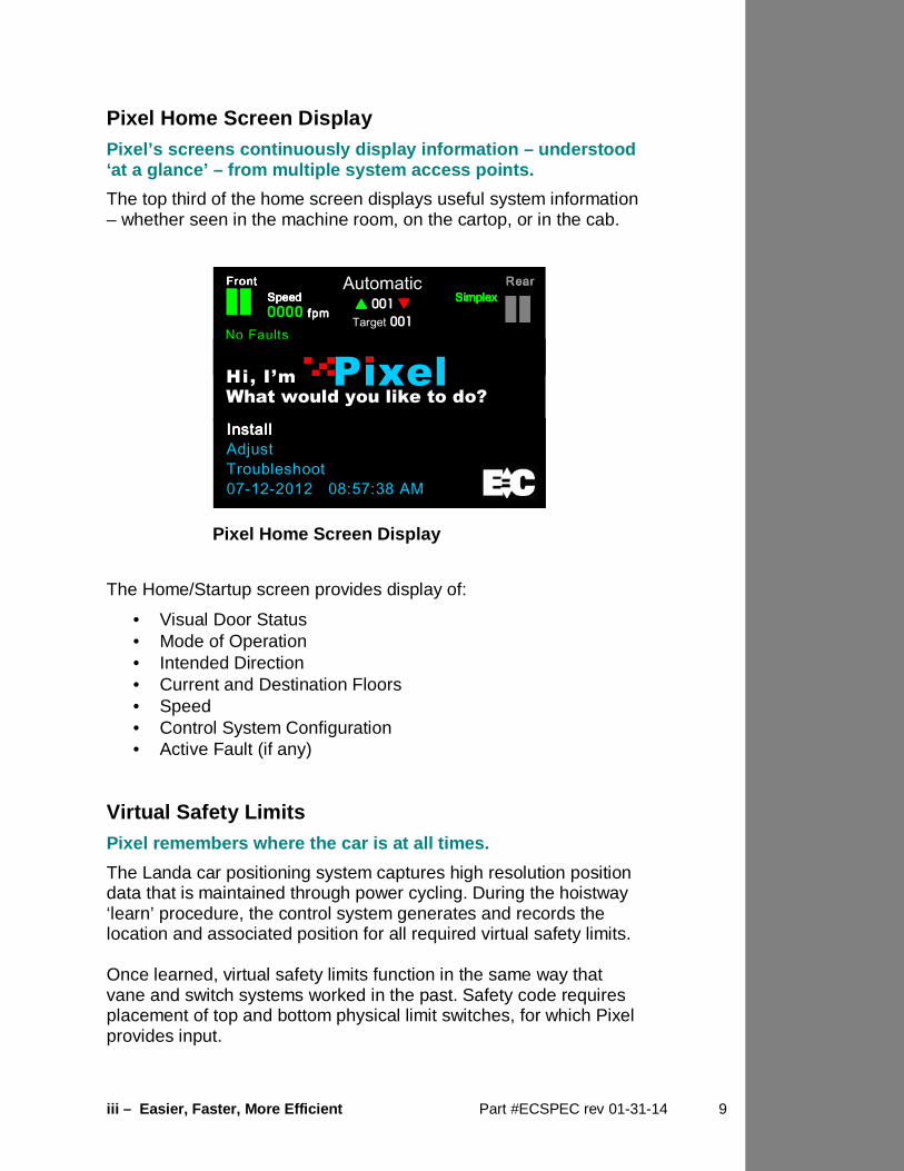
Pixel Home Screen Display Pixel’s screens continuously display information – understood ‘at a glance’ – from multiple system access points.
The top third of the home screen displays useful system information – whether seen in the machine room, on the cartop, or in the cab.
The Home/Startup screen provides display of:
• Visual Door Status • Mode of Operation • Intended Direction • Current and Destination Floors • Speed • Control System Configuration • Active Fault (if any)
Virtual Safety Limits Pixel remembers where the car is at all times.
The Landa car positioning system captures high resolution position data that is maintained through power cycling. During the hoistway ‘learn’ procedure, the control system generates and records the location and associated position for all required virtual safety limits. Once learned, virtual safety limits function in the same way that vane and switch systems worked in the past. Safety code requires placement of top and bottom physical limit switches, for which Pixel provides input.
Pixel Home Screen Display
InstallInstallInstallInstall Adjust Troubleshoot 07-12-2012 08:57:38 AM
Front Front Front Front RearRearRearRear SpeedSpeedSpeedSpeed SimplexSimplexSimplexSimplex 0000 fpmfpmfpmfpm No Faults
Automatic
�������� 001 ��������
Target 001
Hi, I’m Pixel What would you like to do?

iii – Easier, Faster, More Efficient Part #ECSPEC rev 01-31-14 10
Parallel Independent Safety Processors If at any time, Pixel’s two independent safety syst ems do not agree, an automatic system shutdown is executed to keep passengers safe.
In compliance with current elevator safety code, Pixel’s design incorporates parallel independent safety processors. Two independent, redundant means are used to monitor safe operation. The logic output from both safety systems is continually compared. EC design engineers devised SP1, a powerful software-based safety processor, which is continually crosschecked by SP2, a hardware-based FPGA (floating point gate array) safety processor. Integrated I/O Testing and Remapping Local diagnostics function whether or not the acces s point has an active connection to the system network.
Pixel has designed-in reliability and flexibility. Simple onboard I/O testing is supported at each system access point. Every I/O is provided with an associated LED indicator. If an I/O is found to have failed, remap I/O can be used to reassign this I/O to another location on the same PC board, or to another I/O board, using an intuitive, visually-based process. Consolidated Field Wiring Consolidated field wiring saves time while separati ng low and high voltage signals to help prevent component dama ging wiring errors.
The Pixel controller cabinet has been designed so you can bring field wiring into a functionally assigned, coded, terminal strips – a convenience we call consolidated field wiring. Field wiring connects to separately coded strip connector terminals, and enclosure layouts include attention to providing sufficient “big hand” working room. Remote Assist TM Virtual tech support is delivered to your machine r oom on demand – with system access you always approve and control.

iii – Easier, Faster, More Efficient Part #ECSPEC rev 01-31-14 11
Elevator mechanics have long wished that support technicians could join them in the machine room with a simple call for help. Remote Assist enables the Pixel technical support team to virtually view the system you are working on, in real time, and provide guidance and recommendations. Pixel Menu System Menu content is strategically organized, and logical ly sequenced, with related tasks grouped together.
The broad range of selections within the Pixel system are presented in menus, each containing a reasonable number of selections within each tier. The number of tiers has also been minimized to simplify navigation and selection. The breadth and depth of the Pixel menu system provides access to the extensive parameters demanded by the most experienced adjuster. But many installers will find that the top two or three menu tiers will satisfy the majority of their needs.

iv – About Elevator Controls Part #ECSPEC rev 01-31-14 12
iv About Elevator Controls Elevator Controls – established in 1986 – is a high ly regarded manufacturer of Non-proprietary microprocessor-base d elevator controls. Over 30,000 Elevator Controls u nits are in service worldwide. Independent Ownership Elevator Controls is independently owned, and actively managed, by Fernando Ortiz, President and Chief Operating Officer, and Francisco Ortiz, Executive Vice President and Product development director. Our early history is the story of how microprocessor-based control systems were pioneered as this technology began to replace relay-logic systems. During the development of our product line, we identified internal standards for software, form factor and plug-in compatibility that enabled the newest PC boards to work in older equipment. This discipline provided our growing customer base with simplified maintenance, reduced spares requirements, and enabled service life to be indefinitely extended. EC has continued to invent, and we’ve been fortunate to attract, develop, and retain an expanding team of talented and experienced engineers to provide R&D, project engineering, and customer support. During over 2-1/2 decades serving the elevator industry, our manufacturing processes have evolved to meet increasingly stringent quality standards. But the determination we had back in 1986 – to produce the safest, most reliable products, at a fair price – is still our guiding principal.
v – How To Use These Specifications Part #ECSPEC rev 01-31-14 13
v How to Use These Specifications Start with Pixel General Specifications Section 1 to compile a control system spec for your project. For reference, enclosure dimensions and conditions for equipment operating environment(s) are located in Section 12, Physical Specifications. Choose optional features from Section 7 as required. You will find that Pixel includes many features and options as standard.
Wiring harnesses for each COP-to-TOC cartop connection are included. Advanced c-LINK TM serial communication is standard and fully integrated with the Pixel system. Consider additional features , including Interact TM Central Monitoring, Motors and Machines, Load Weighing, and a range of Security options. Descriptions start with Section 6. Non-Proprietary “Serviceable & Maintainable” Products that carry the Elevator Controls brand label are provided with onboard Non-Proprietary diagnostics and are designed to satisfy the list of functional requirements below. Incorporate the following language in your Project Specifications to ensure that you receive all the benefits of “Serviceable and Maintainable” equipment:
1. Diagnostics : All diagnostics shall be provided onboard.
2. Service Tool : No service tool shall be required for equipment installation, adjustment, maintenance or troubleshooting.
3. Parts : Spare or replacement parts shall be available at published prices to anyone without restriction.
4. Training: Regularly scheduled technical training classes shall be available at reasonable cost to anyone without restriction.
5. Telephone Support : Telephone hotline support shall be available from trained, experienced technicians.
6. Field Support : Field engineering support shall be available at the customer’s location by prior arrangement at reasonable cost.
7. Documentation : All installation, adjustment, maintenance and troubleshooting manuals and documents required for proper equipment operation shall be provided with equipment at time of delivery. As-built prints shall be included. Replacement copies of these documents shall be readily available at reasonable cost.
v – How To Use These Specifications Part #ECSPEC rev 01-31-14 14
How to Specify To write Project Specifications ensuring that Elevator Controls equipment is provided, you may elect to include language such as:
• [Sole Source ] Control equipment shall be provided by Elevator Controls
• [Sole Source ] Control equipment shall be provided by Elevator Controls, no known equal
• [Sole Source or approved Alternate ] Control equipment shall be provided by Elevator Controls or approved equal
In some circumstances, a functional specification can have the effect of creating a Sole Source, when desired, by including the following language:
• Telephone Technical Support Availability Telephone Technical Support shall be provided for customers at no charge.
• The Controller Manufacturer shall have a track record of over 25 years in business manufacturing Microprocessor-based elevator controllers.
• PLC-based controllers shall not be accepted.
• User Interaction Switchgear shall be consolidated in a single physical area or dashboard.
• The System Human Interface shall be comprised of a high
resolution color display, with functions navigated and selected using a single, multi-function knob.
• Multiple Locations for System Access shall be provided,
including the machine room, cartop, and cab. • Local Diagnostics shall function regardless of whether a
particular access point has an active system network connection.
• A Help System shall be incorporated and embedded in the
control system.
• A Help Button shall be provided. When pressed, this function shall cause context relevant help to be displayed on screen.

v – How To Use These Specifications Part #ECSPEC rev 01-31-14 15
• The Cab Positioning System shall not require floor or slowdown vanes, switches or wiring to be installed in the hoistway. The system shall codify the hoistway in a way not requiring rotary enconders, floor counters, or physical contact between sensing and actuating devices, eliminating wear and tear.
• Cab Position Shall Be Continuously stored in non-volatile
memory such that high resolution position data is maintained during normal operation and through a power cycling event.
• Placement of Safety Limits shall be accomplished virtually,
without requiring placement of any hoistway switches or hardware, except physical top and bottom limit switches as required by safety code.
• Every I/O Location Shall be Equipped with an Associ ated
LED Indicator to visually confirm status and an active connection.
• The Control System Shall Support I/O Remapping to an
alternate location on the same PC board, or to another I/O board, using an intuitive, visually-based process.
• The Control System Shall Incorporate Two Independen t
Safety Processors to monitor safe operation. One safety processor shall be software based, while the other shall be hardware based. Either shall be capable of commanding a system shutdown.
• Remote Technical Support shall be available able to
enable authorized factory technicians to obtain virtual access to the control system to provide assistance.
• A Standard 15 Month Warranty shall be provided,
commencing at time of shipment.
• Safety Code Compliance Shall be Confirmed through application of tests described in control equipment documentation, including compliance with Part B, Redundancy and Monitoring in Critical Circuits per ASME A17.1-2007Sections 2.29.9.3 and 2.26.9.4 or current equivalent.

vi – Warranty & Support Part #ECSPEC rev 01-31-14 16
vi Warranty & Support
Before attempting to install Elevator Controls products, please read and familiarize yourself with the proper installation manual(s).
Elevator Controls warrants its products to be free from defects in materials and workmanship for a period of 15 months from the date of shipment by Elevator Controls . Any defect appearing more than 15 months from the date of shipment by Elevator Controls shall be deemed to be due to ordinary wear and tear. Elevator Controls assumes no risk or liability for results of the use of products purchased from it, including but without limiting the generality of foregoing: (1) the use in combination with any electrical or electronic components, circuits, systems assemblies or any other materials or substances; (2) unsuitability of any product for use in any circuit or assembly or environment. Satisfaction of this warranty, consistent with other provision herein, shall be limited to, at the sole discretion of Elevator Controls , repair, replacement, or modification of the product, free of charge, F.O.B. factory. This warranty applies to any product which is received at the factory within said 15 months and which, upon examination by Elevator Controls , is determined to have a defect which has not been caused by misuse, neglect, improper installation, improper application, improper operation, improper maintenance, repair or alteration, accident, or unusual deterioration or degradation of the equipment or parts thereof due to physical environment or due to electrical or electromagnetic noise environment. Should purchaser experience trouble or difficulty with any product of Elevator Controls and request engineering assistance either by telephone or a field visit or visits by a representative of Elevator Controls , Elevator Controls may, at its sole discretion, provide said assistance. Should, in the opinion of Elevator Controls , the trouble or difficulty be a warranty problem as herein described, Elevator Controls will absorb all travel, labor, and expense costs involved. Should, in the opinion of Elevator Controls , the trouble or difficulty be a result of any other reason than the warranty described herein, the purchaser will be charged for the travel, labor, and expense costs by Elevator Controls , for providing engineering assistance, whether it be by telephone, correspondence, or field visit or visits by a representative of Elevator Controls . A schedule of fees is available on request for engineering services by Elevator Controls . The giving of or failure to give any advice or recommendation by Elevator Controls shall not constitute any warranty by or impose any liability upon Elevator Controls . This warranty constitutes the sole and exclusive remedy of the purchaser and the exclusive liability of the manufacturer, AND IS IN LIEU OF ANY AND ALL OTHER WARRANTIES, EXPRESS, IMPLIED, OR STATUTORY AS TO MERCHANTABILITY, FITNESS FOR PURPOSE SOLD, DESCRIPTION, QUALITY, PRODUCTIVITY, OR ANY OTHER MATTERS. In no event shall Elevator Controls be liable for special or consequential damages or for delay in performance of this warranty.

vi – Warranty & Support Part #ECSPEC rev 01-31-14 17
Telephone Technical Support Telephone Technical Support shall be provided for Customers at no charge.
• Installation, adjustment and troubleshooting support are provided by knowledgeable, factory trained technicians.
• Multi-lingual telephone support is available.
• Product R&D engineers stand ready to respond to particularly challenging questions.
• Onsite product and engineering support is available worldwide by prior arrangement.
Call 916/428-1708 800/829-9106
Fax 916/392-6852
Email [email protected]
Section 1 – Pixel General Specifications Part #ECSPEC rev 01-31-14 18
Section 1 Pixel General Specifications 1.0 General This section describes features and/or requirements common to all Pixel control systems manufactured by Elevator Controls . 1.1 Code Compliance Every elevator controller shall use a microprocessor-based logic system and shall comply with elevator and electrical safety codes applicable to the jurisdiction in which installation of equipment is intended. Customer shall bear sole responsibility for: (1) identifying the Authority Having Jurisdiction (AHJ) and; (2) verifying and communicating the code/s and requirements with which equipment must comply. The engineering data forms submitted for a project shall constitute sole authorization to manufacture equipment to comply with specific code/s. Any changes must be submitted in the form of a written data form amendment, clearly marked as superseding form/s previously submitted. It is critical that the customer understand the imp lications of code compliance designated on data forms. 1.2 ADA Requirements The elevator controllers shall comply with Title III of the Americans with Disabilities Act (ADA). Car Lanterns - The controller shall have outputs to drive the visible and audible signals that are required to indicate when elevator car is answering a call. Audible signals shall sound once for up, twice for down. Optionally, Hall Lantern outputs shall be provided to drive visible and audible signals at each hoistway entrance to indicate which elevator car is answering a call. Car Position Indicators - The controller shall have a position indicator output to drive the required position indicator which shall indicate the corresponding floor numbers as the car passes or stops at a floor. An audible signal shall sound as the position indicator changes floors. OPTIONAL – A voice annunciator output shall be provided in order to interface with an annunciator module, provided by others, to announce direction and floor number.

Section 1 – Pixel General Specifications Part #ECSPEC rev 01-31-14 19
1.3 Operating Environment
Machine Room Temperature Ambient air temperature range 32º to 104º F (0º to 40º C)
Maximum Inside Enclosure Shall not exceed 122º F (50º C)
Operating Temperature 32º F to 122º F (0º C to 50º C)
Storage Temperature -22º F to 150º F (-30º C to 65º C)
Humidity 10% to 90% non-condensing
Altitude Up to 7500 feet (2286 m)
Elevator Controls specializes in making control products for adverse environmental conditions. For example, dust-proof, water-proof, corrosion-resistant, explosion-proof, or air-conditioned controller cabinets can be engineered to meet specific applications. Please contact Elevator Controls for details. 1.4 Out of Service Timer An out of service timer (T.0.S.) shall be provided to take the car out of service if the car is delayed in leaving the landing while there are calls existing in the system. 1.5 Door Pre-Opening When selected, this option shall permit doors to start to open when the car is in final leveling, from an adjustable distance from 3" (76.2 mm) from the floor. If pre-opening is not selected, the doors shall remain closed until the car is at the floor, at which time the doors shall commence opening. 1.6 Simplex Selective Collective Operation Simplex selective collective automatic operation shall be provided for all single car installations. Operation of one or more car or hall call pushbuttons shall cause the car to start and run automatically, provided the hoistway door interlocks and car door contacts are closed. The car shall stop at the first car or hall call set for the direction of travel. Stops shall be made in the order in which car or hall calls set for the direction of travel are reached, regardless of the order in which they were registered. If only hall calls set for the opposite direction of travel of the elevator exist ahead of the car, the car shall proceed to the most distant hall call, reverse direction, and start collecting the calls. 1.7 Simplex Home Landing Operation OPTIONAL - If no calls are registered, and after a user defined delay expires, this operation shall cause the car to travel to a predetermined home landing

Section 1 – Pixel General Specifications Part #ECSPEC rev 01-31-14 20
floor and stop without door operation. The home landing function shall cease immediately on registration of a normal call. 1.8 Group Dispatching Operation The system shall provide a means of supervising, dispatching and coordinating the movement of individual elevator cars in a group. Two or more cars shall be capable of working together to facilitate group dispatching, up to a total of 12 cars per group, to maximize efficiency in serving varying elevator traffic needs in the building while minimizing passenger waiting time. 1.8.1 Master / Slave Redundant Distributed Dispa tching Group operation shall require establishment of communication between all cars in service configured as group participants. Once communication is established, the system shall automatically assign control of dispatching to a particular car controller (for reference, identified as a master car). The car controller selected, with no user intervention or action required, shall commence generation and communication of dispatching instructions to all other car controllers in the group. Every car controllers shall be capable of functioning as either a master or slave for dispatching purposes. Current dispatching data – including but not limited to registered calls, car and hall call demand, and underlying computational data required for dispatching decisions – shall be shared by the master car with all other cars. In the event that the current master dispatcher becomes unavailable to perform its function, any other car functioning as a group member shall be capable of seamlessly assuming dispatching control for the entire group. Transition of dispatching responsibility from one car to another shall be transparent, preserving all current dispatching data and assignments. The “new” dispatcher shall reassign any calls assigned to the previous master car with no interruption in service or loss of registered calls. 1.8.2 Primary Dispatch Methodology The dispatching system shall continuously inventory the number of cars in service, car location, car direction, hall call demand, and car call demand for all floors served. Based on a rolling forecast of the estimated the time required to serve all calls, the dispatching system shall determine which car is in the optimum location for assignment of a particular hall call. If the system determines that the car in the best location will exceed a desired maximum response time estimate, another available car shall be assigned.
Section 1 – Pixel General Specifications Part #ECSPEC rev 01-31-14 21
The efficient movement of elevators in response to hall calls shall not only deliver the desired response time but shall also minimize wear and tear by eliminating needless movement of the elevators, enhancing the life expectancy of elevator equipment. 1.8.3 Dynamic Efficiency Improvement The system shall continuously and dynamically update, assign, and reassign cars to hall calls in order to address current, real time conditions as conditions change in the building. Dispatching operation shall be easily reconfigured to accommodate any combination of front, side, or rear elevator door openings. The method of call assignment shall be selected based on real time, electronic calculations designed to continuously evaluate traffic demand and system status. Automatic and continuous adjustment of call assignment method and call reassignment shall be transparently implemented to optimize estimated time of arrival (ETA), consistent with minimum elevator travel. The system's dynamic selection algorithm shall make preliminary car-to-call assignments based on best call response time, derived from the car's position and direction. The final assignment shall evaluate multiple parameters including, but not limited to, the following:
a. Number of hall calls ahead of the car. b. Number of car calls ahead of the car. c. Response time to stops ahead of the car. d. Coincident calls. e. Maximum hall call response time.
If a call is registered for which not all cars are eligible to respond, such as a rear call where not all cars are capable of answering, the system shall automatically make an optimum selection from eligible cars. 1.8.4 Emergency Dispatch Operation In the unlikely event that dispatching instructions are unable to be generated or communicated to group system members, individual car controllers shall revert to Emergency Dispatch Operation. This mode shall enable cars to continue to run, stopping at their assigned floors in both the up and down direction. Emergency dispatch operation shall place all elevators in continuous service until group system operation is restored. Assignment of floors in emergency operation shall ensure that only one car serves any particular floor, and all cars serve the main lobby floor.

Section 1 – Pixel General Specifications Part #ECSPEC rev 01-31-14 22
1.8.5 Access to Dispatching Parameters and Diagnost ics Dispatching system architecture shall accommodate major changes in building occupancy or physical configuration as routine. Pertinent variables relating to system performance shall be easily reprogrammed without hard wiring changes or a system shutdown. All dispatching system parameters and diagnostics shall be accessible using multiple integrated system access points. No external tools or troubleshooting devices shall be required. 1.9 Number of Stops All controllers shall be capable of serving up to 128 landings. 1.10 Leveling The car shall be equipped with two-way leveling to automatically bring the car level at any landing, within the required range of leveling accuracy, with any load up to full load. 1.11 Landing Systems Landing System options are described in detail in Section 8. 1.12 Uncancelled Call Bypass A timer shall be provided to limit the amount of time a car is held at a floor due to a defective hall call or car call, including stuck pushbuttons. Call demand at another floor shall cause the car, after a predetermined time, to ignore the defective call and continue to provide service in the building. 1.13 Anti-Nuisance (Photo-Eye) The controller computer shall cancel all remaining car calls, if an adjustable number of car calls are answered without the computer detecting a photo eye input. 1.14 c-LINK TM Serial Communication STANDARD – The elevator control system shall incorporate COP and hall nodes that communicate using an advanced CAN-bus serial communication system. Serial Communication allows multiple signals to share the same wiring. Enhanced c-LINK , integral to every Pixel control system, shall reduce wire count for hall, car and cartop signals without compromising safe and sensible standards. This system shall reduce the traveler conductor count, and time, labor and material otherwise required to run dedicated wires for each signal. c-LINK interconnection shall be accomplished for Hall Stations and Car Operating Panels through use of EC-Ready fixtures, which shall be available
Section 1 – Pixel General Specifications Part #ECSPEC rev 01-31-14 23
from multiple participating suppliers. Interconnection for Cartop signals shall be accomplished using a cartop interface box which shall be provided by the controller manufacturer. 1.15 Optional Peripherals OPTIONAL - As an integral part of the controller, the capability shall be provided to attach on site or remote computer peripherals, yielding additional adjustment or diagnostic capabilities. 1.16 Optional Features OPTIONAL – InteractTM central monitoring, Limit Switches, Motors and Machines, Load Weighing, and Security are available. Brief descriptions follow. Full descriptions can be found in the sections indicated. 1.16.1 Interact TM Central Monitoring OPTIONAL - Interact TM, our answer to central and remote elevator monitoring, provides instant insight for elevator system performance. Many convenient, easy to use functions have been combined into a single software product. This command and control system for elevators is both interactive and intuitive, satisfying the needs of diverse users. For comprehensive monitoring solutions that include elevators, escalators and moving walkways of diverse age and brand, Elevator Controls provides universal monitoring solutions partnering with IDS Lift-Net. Details of monitoring options are described in Section 10. 1.16.2 Security OPTIONAL - EC Basic Security prevents unauthorized individuals from entering car calls and allows only authorized individuals to access restricted floors. Basic Interact Security with Display enhances EC Basic Security by providing the ability to activate or deactivate access restrictions from a machine room Display or remote system monitoring Display running Interact TM monitoring software. Options include interfacing to various types of Card Reader Systems, Floor Key Lockout operation, and Anti-Terrorism Control. Security options are described in detail in Section 11. 1.16.3 Motors & Machines OPTIONAL – Elevator Controls provides motors and machines designed specifically for elevator duty applications. Controller/motor packages provide one-call ordering convenience and the assurance that all components will work well together. Motor and Machine options are described in detail in Section 6. 1.16.4 Load Weighing OPTIONAL – Load Weighing options are described in detail in Section 9.

Section 2 – Pixel AC Traction Elevator Controls Part #ECSPEC rev 01-31-14 24
Section 2 Pixel AC Traction Elevator Controls Overview Pixel Model AC Traction Elevator Controls Corporation is a highly regarded manufacturer of Non-proprietary, microprocessor-based elevator controls. Our equipment is designed and engineered using appropriate, proven technology… to ensure years of field reliability. The Pixel control system has been designed to save field labor time. For example, this digital elevator control system provides three points of system access – Machine Room, Cartop, and Inside the Cab – so the most convenient location can be used to complete tasks quickly and easily. Elevator Controls Pixel Model microcomputer based AC Controller utilizes surface-mount electronic components, large scale integrated circuits, and state-of-the-art PC boards to enhance overall reliability. The Pixel AC VF-Traction system is uniquely suited for applications including either AC-Vector controls for Induction motors, or Closed-Loop Vector Control for PM motors, providing precise speed regulation better than 1% and with contract speed up to 1400 FPM (7 m/s). A high accuracy, continuous operating Position Velocity Feedback (PVF) system is integral to the Pixel control system design. Position feedback software obtains precise information from the LandaTM dual positioning system. Landa provides absolute cab location information without the need for vanes or switches in the hoistway (top and bottom physical limit switches must be provided as required by elevator safety code). Dual communication channels, one for each positioning system, provide truly independent redundancy for failsafe operation. Integrated position velocity feedback, and precision cab positioning accuracy to within 0.8 millimeter, provide every elevator with a features previously only available on the highest speed cars on high profile projects. Benefits include more consistent speed parameter execution for a higher quality ride and adaptability to a variety of floor heights eliminating most “short” floor issues. 2.0 General Specifications Pixel AC Traction The basic simplex elevator control system shall be comprised of a computer microprocessor, a dual safety processor, an I/O structure and a relay interface in addition to a power supply, control transformer, contactor, and AC motor drive.

Section 2 – Pixel AC Traction Elevator Controls Part #ECSPEC rev 01-31-14 25
A standard CAN-BUS connection shall enable the control system to become a network device, capable of communicating with a wide variety of other devices. A standard PC shall provide remote communication and enable elevator system performance reports to be generated and distributed. An embedded, distributed dispatching system shall support a group of up to 12 cars, each of which shall be capable of serving as many as 128 landings. A cartop interface box shall be provided with the control system to provide a convenient wiring termination for:
a. Landa positioning system b. Door operator/s (up to three per cab) c. Load weigh device d. Door safety edge/s (up to three pair per cab) e. Light and fan connection f. Traveler cable g. TOC-to-COP wire harness (up to four provided, one for each COP)
The cartop interface shall also function as a system access point, provides access for configuration information, viewing and adjusting system parameters, and accessing onboard diagnostics. OPTION – The cartop interface box shall optionally be upgraded to a complete cartop inspection station, with light and service outlet, in addition to providing all the functions listed above. A car operating panel interface shall be provided for each COP (up to four per cab). This interface shall function as a system access point . EC-Ready COP fixtures fully interconnect to the TOC box using the provided TOC-to-COP harness . One wiring harness shall be provided for each of up to four COP’s per cab. Universal hall nodes shall provide connections for hall calls, fire recall, access, hall gongs, code blue calls and other signals, functions and devices. Each CAN-driven node shall support two or more I/O, easily configurable using onboard switchgear. 2.0.1 Fire Service The fireman service operation and normal operating features shall be incorporated in accordance with the American National Standard Safety Code (ANSI A17.1) and applicable state and local codes. 2.0.2 Selective Door Timing Adjustable timing parameters shall be provided to control door dwell time for passenger transfer. Independently adjustable, user defined standard and short

Section 2 – Pixel AC Traction Elevator Controls Part #ECSPEC rev 01-31-14 26
door times shall be set without requiring a system shutdown. A minimum of four different door standing open times shall be provided. A car call time value shall predominate when only a car call is canceled. A hall call time value shall predominate whenever a hall call is canceled. An independently adjustable parameter shall also be provided to control door reversal time. Activation of the photo eye input shall optionally cause short door timing to be used. An adjustable parameter shall be provided to control door dwell time during up peak operation, which shall be defined independent of any other door timing. 2.0.3 Door Operation Door protection timers shall be provided, for both opening and closing directions, which will protect the door motor and help prevent the car from getting held up at a landing. The door open protection timer shall cease attempting to open the door, after a predetermined time, in the event that the doors are prevented from reaching the open position. In the event that a door closing attempt fails to make up the door locks, after a predetermined time, the door close protection timer shall reopen the doors for a user defined time interval. 2.0.4 Nudging Operation OPTIONAL - If doors are held open beyond a predetermined adjustable time, a buzzer shall sound and doors shall begin closing with reduced torque. Activation of the safety edge input shall be ignored during nudging operation. Activation of the safety edge input shall optionally enable door reopening during nudging operation. 2.0.5 System Dashboard Interface The control system shall concentrate switchgear, indicators, readouts and a color LCD display into an intuitive dashboard located in the control system enclosure. Additional system access points shall be provided on the cartop, and inside the car operating panel. The control system shall display information on a vivid, full color LCD screen at each system access point. Instant real-time awareness of current car operation shall be readily available and easily accessed. 2.0.6 Redundant Safety System The control system shall be equipped with parallel safety processors comprising two independent, redundant means to monitor safe operation. The logic output from both safety systems shall be continually compared. If, at any time, these safety systems do not agree, an automatic system shutdown shall be immediately executed.

Section 2 – Pixel AC Traction Elevator Controls Part #ECSPEC rev 01-31-14 27
The control system shall incorporate a powerful software-based safety processor which is continually crosschecked by a hardware-based FPGA (floating point gate array) safety processor. 2.0.7 Independent Service Independent service operation shall be provided such that activation of a key switch in the car operating panel (COP) cancels all existing car calls and holds the doors open at the landing. When the key switch is activated, the car shall only respond to car calls disregarding all hall calls. Constant pressure on a car call button or a door close button shall be required, until the car starts to move, in order to close hoistway and car doors. All hall and jamb mounted lanterns shall be inactive when independent operation is activated. 2.0.8 Test Switch Switchgear shall be provided on the controller dashboard to enable operation for adjustment of the elevator. While in test mode, the elevator shall operate as in independent service, without the door open function. When the test switch is activated, the elevator shall be removed from any group, operating independently. 2.0.9 Capture Switch A switch shall be provided on the controller dashboard to enable service personnel to disallow the car from answering hall calls, and remove the car from normal operation. The capture car shall be removed from normal operation upon completion of passenger unloading at the last car call registered prior to activating the capture function. 2.0.10 Inspection Switch Inspection and up/down switchgear shall be provided on the controller dashboard to allow the elevator car to be controlled manually in inspection mode of operation. Inspection operation shall only be enabled when the top-of- car and in-car inspection switches are not active, and all safeties and door protection circuits are on normal operation. 2.0.11 Built-in Diagnostics Powerful yet simple to use diagnostics shall be built into the control system. Capabilities shall include extensive onsite reconfiguration and tailoring of elevator “personality” parameters via vivid color LCD screen interface. The home screen shall continuously display information including visual door status, mode of operation, intended direction, current and destination floors, speed, control system configuration, and active faults ordered by priority (if any), or an indication of no faults.

Section 2 – Pixel AC Traction Elevator Controls Part #ECSPEC rev 01-31-14 28
The built-in digital diagnostics system shall be capable of displaying current fault status and details as diagnosed by internal logic. Additional inquiry and display capabilities shall include user configurable parameters, current faults, fault history, security parameters, car and hall calls registered, control program “flags”. The diagnostic system shall enable a qualified service technician to accomplish the following without requiring a system shutdown: enter calls, configure parameters (including but not limited to car stopping table, control timers), configure special functions (i.e.: fire/parking floors, gong dinging control, group call assignments, and automatic program selection parameters), and access special optional features (i.e.: building security access codes). In addition to information pertaining to user defined parameters, the following diagnostic information shall be accessible by a qualified service technician, without requiring any connection of external tools or the use of a PC, to make use of built-in diagnostics functions.
• Input/Output Status • Speed Tracking Performance • Fault logs retrieval • Trip Sequence Log • Fault Sequence Playback • Hoistway Floor Position Data • Terminal Landing Velocity Data
Other functions which may currently be available or added to standard system diagnostic capabilities 2.0.12 Field Configurable Parameters The elevator controller shall include provisions for viewing and changing field configurable parameters, which shall include but not be limited to the following. All parameter changes shall immediately take affect without requiring a system shutdown:
Ride Performance a. Auto Car Call Simulation b. Speed Profile Parameters c. Drive Unit Basic d. Drive Unit Advanced e. Motor/Brake Timers
Car Performance
f. Timers g. Fire Service Options h. Eligibility Tables

Section 2 – Pixel AC Traction Elevator Controls Part #ECSPEC rev 01-31-14 29
i. Door Operation j. Traction Options k. Functional Options l. Emergency Power Options m. Hospital Service Options n. Miscellaneous Options o. COP Floor Security p. Event Outputs
Group Performance
q. Car Per Group Timers r. Group Dispatching Timers s. Dispatching Functions t. Zone Partitions
Viewing and changing parameters shall be accomplished through use of intuitive navigation switchgear and menus displayed on a vivid color LCD screen. 2.0.13 Loaded Car Operation OPTIONAL - Should any car become loaded to a user preset adjustable load level, all door dwell timers shall be advanced to zero, and car doors shall close without delay. Additionally, the car shall be automatically removed from group availability until the car load is reduced below the preset threshold. 2.0.14 Light Load Anti-Nuisance Operation OPTIONAL - All registered car calls shall be canceled, if a user preset adjustable number of entered car calls is exceeded, and the load in the car has not caused the light load switch to open. If a user preset adjustable number of car calls are answered without activation of the photo eye input, all registered car calls shall be canceled. 2.1.1 Position and Velocity Feedback System A position feedback system shall be provided which is capable of continuously adjusting the mathematically computed optimal speed output as a function of distance from the target floor. The control system shall produce an optimized velocity profile utilizing a dual-loop feedback system based on car position and speed. Systems that generate speed profile as a time-based function during deceleration, rather than a position-based function, shall not be accepted. During deceleration the system shall function in such a way to provide accurate positioning of the elevator through final leveling without passenger discomfort, regardless of car load or direction of travel.
Section 2 – Pixel AC Traction Elevator Controls Part #ECSPEC rev 01-31-14 30
2.1.2 Position and Velocity Feedback Software The control system shall continuously apply mathematical equations and evaluate outcomes in order to create an idealized, optimum velocity profile for the travel of each car from any floor to any other floor. An embedded position feedback subsystem shall continuously adjust the mathematically computed optimal speed output, as a function of distance, from the target floor. The control system shall produce an optimized velocity profile, utilizing a dual-loop feedback system based on car position and speed. Systems that generate speed profile as a time-based function during deceleration, rather than a position-based function, shall not be accepted. During deceleration, the system shall function in such a way as to provide accurate cab positioning information through final leveling, without passenger discomfort, regardless of car load or direction of travel. This system shall provide a smooth and stepless elevator ride. All system motion parameters (including jerk, acceleration, deceleration rates, etc.) shall be user defined, within parametric limitations for system dynamics, and shall be stored in nonvolatile memory. Adjustment of these parameters shall not require the connection of any external device. Built-in programming and diagnostics with user-friendly, “plain English” display shall be provided. A position feedback system shall establish incremental car position within the elevator hoistway. Digital feedback of car position shall be generated by the Landa positioning system as the elevator travels the entire length of the hoistway. This system shall enable the elevator car to be positioned with accuracy of within 1 mm, or better. Leveling control shall provide car-to-floor leveling accuracy of ¼ inch. Compensation shall be provided for overtravel, undertravel, or rope stretch such that the car is brought level to the landing sill. An electronic safety shall continuously monitor the car speed signal from the velocity transducer, and compare it with the intended speed signal, to verify proper and safe elevator operation. 2.1.3 Motor Drive A solid-state motor drive in each individual controller shall provide power for an AC hoist motor. The motor drive shall be a compact, self-contained unit providing regulation of stepless acceleration and deceleration, utilizing speed

Section 2 – Pixel AC Traction Elevator Controls Part #ECSPEC rev 01-31-14 31
feedback from a tachometer or digital encoder. Variables shall be digital and user definable without the need for any external device, or knowledge of any special programming language. The motor drive shall be capable of controlling an AC motor (be it induction, or permanent magnet type, for geared or gearless applications, including Remote Machine Room locations such as MRL’s ) to maintain 2 to 5% speed regulation under varying loads. The drive system shall control output power to the AC hoist motor which will control the speed of the elevator. A means shall be provided for removing regenerated power from the drive system DC power supply. This power shall be dissipated in resistors or be returned to the three phase AC power line. Failure of the system to remove the regenerated power shall cause the drive output to be removed from the hoist motor. OPTION – The Pixel AC Traction Controller can be optionally provided with Magnetek’s Quattro® AC Elevator Drive that shall provide: • Regenerative Power Conversion for AC Motors • Clean Utility Side Harmonics (<8% THDI) • Near Unity Power Factor (P.F.>0.95) • Multiple Input Voltage Ranges
• 200-480 VAC, 50/60 Hz
• Elevator Rated
• 250% Overload
• And it shall meet:
• ASME A17.1-2000. 2.26.9.6 • EN12015 (Emissions) • EN12016 (Immunity)
An AC rated contact shall be used to disconnect the hoist motor from the output of the drive unit each time the elevator stops. A velocity feedback subsystem shall provide continuous comparison of actual cab speed to the idealized velocity profile, in order to provide accurate control of acceleration and deceleration through final leveling without passenger discomfort, regardless of car load or direction of travel.
Section 2 – Pixel AC Traction Elevator Controls Part #ECSPEC rev 01-31-14 32
2.1.4 User Defined Speed Profile Parameters Variables shall be user configurable without the need for any external device, or knowledge of any special programming language. Parameters shall include, but not be limited to:
a. Contract speed b. Number of floors c. Initial jerk d. Roll over jerk e. Deceleration jerk f. Pattern delay g. Acceleration h. Deceleration i. Leveling distance j. Leveling speed k. Releveling speed l. Inspection speed m. Tach polarity n. Tach gain
2.1.5 Hoistway The system shall be capable of automatically “learning” the position of each floor and all terminal slowdowns using a procedure that simply requires running the car the length of the hoistway. As part of this procedure, the correct speed at each slowdown shall be automatically recorded in non-volatile memory. The Cab Positioning System shall not require floor or slowdown vanes, switches or wiring to be installed in the hoistway. The position system must codify the hoistway in a way not requiring rotary enconders, floor counters, nor physical contact between sensing and actuating devices, or tape guides (eliminating maintenance from wear and tear). Placement of Safety Limits shall be accomplished virtually, without requiring placement of any hoistway switches or hardware, except physical top and bottom limit switches as required by safety code. . No magnets nor additional sensors shall be required for detection of the car position throughout the hoistway.
Section 3 – Pixel DC Traction Elevator Controls Part #ECSPEC rev 01-31-14 33
Section 3 Pixel DC Traction Elevator Controls Overview Pixel Model DC Traction Elevator Controls Corporation is a highly regarded manufacturer of Non-proprietary, microprocessor-based elevator controls. Our equipment is designed and engineered using appropriate, proven technology… to ensure years of field reliability. The Pixel control system has been designed to save field labor time. For example, this digital elevator control system provides three points of system access – Machine Room, Cartop, and Inside the Cab – so the most convenient location can be used to complete tasks quickly and easily. Elevator Controls Pixel Model microcomputer based DC Controller utilizes surface-mount electronic components, large scale integrated circuits, and state-of-the-art PC boards to enhance overall reliability. The closed loop DC-SCR Pixel system is uniquely suited for applications requiring precise speed regulation better than 1% and applications with contract speed of up to 1400 FPM (7 m/s), geared or gearless. A high accuracy, continuous operating Position Velocity Feedback (PVF) system is integral to the Pixel control system design. Position feedback software obtains precise information from the LandaTM dual positioning system. Landa provides absolute cab location information without the need for vanes or switches in the hoistway (top and bottom physical limit switches must be provided as required by elevator safety code). Dual communication channels, one for each positioning system, provide truly independent redundancy for failsafe operation. Integrated position velocity feedback, and precision cab positioning accuracy to within 0.8 millimeter, provide every elevator with a features previously only available on the highest speed cars on high profile projects. Benefits include more consistent speed parameter execution for a higher quality ride and adaptability to a variety of floor heights eliminating most “short” floor issues. 3.0 General Specifications Pixel DC Traction The basic simplex elevator control system shall be comprised of a computer microprocessor, a safety processor, an I/O structure and a relay interface in addition to a power supply, control transformer, contactor, and DC motor drive. A standard CAN-BUS connection shall enable the control system to become a network device, capable of communicating with a wide variety of other devices.

Section 3 – Pixel DC Traction Elevator Controls Part #ECSPEC rev 01-31-14 34
A standard PC shall provide remote communication and enable elevator system performance reports to be generated and distributed. An embedded, distributed dispatching system shall support a group of up to 12 cars, each of which shall be capable of serving as many as 128 landings. A cartop interface box shall be provided with the control system to provide a convenient wiring termination for:
a. Landa positioning system b. Door operator/s (up to three per cab) c. Load weigh device d. Door safety edge/s (up to three pair per cab) e. Light and fan connection f. Traveler cable g. TOC-to-COP wire harness (up to four provided, one for each COP)
The cartop interface shall also function as a system access point, provides access for configuration information, viewing and adjusting system parameters, and accessing onboard diagnostics. OPTION – The cartop interface box shall optionally be upgraded to a complete cartop inspection station, with light and service outlet, in addition to providing all the functions listed above. A car operating panel interface shall be provided for each COP (up to four per cab). This interface shall function as a system access point . EC-Ready COP fixtures fully interconnect to the TOC box using the provided TOC-to-COP harness . One wiring harness shall be provided for each of up to four COP’s per cab. Universal hall nodes shall provide connections for hall calls, fire recall, access, hall gongs, code blue calls and other signals, functions and devices. Each CAN-driven node shall support two or more I/O, easily configurable using onboard switchgear. 3.0.1 Fire Service The fireman service operation and normal operating features shall be incorporated in accordance with the American National Standard Safety Code (ANSI A17.1) and applicable state and local codes. 3.0.2 Selective Door Timing Adjustable timing parameters shall be provided to control door dwell time for passenger transfer. Independently adjustable, user defined standard and short door times shall be set without requiring a system shutdown. A minimum of four different door standing open times shall be provided. A car call time value shall
Section 3 – Pixel DC Traction Elevator Controls Part #ECSPEC rev 01-31-14 35
predominate when only a car call is canceled. A hall call time value shall predominate whenever a hall call is canceled. An independently adjustable parameter shall also be provided to control door reversal time. Activation of the photo eye input shall optionally cause short door timing to be used. An adjustable parameter shall be provided to control door dwell time during up peak operation, which shall be defined independent of any other door timing. 3.0.3 Door Operation Door protection timers shall be provided, for both opening and closing directions, which will protect the door motor and help prevent the car from getting held up at a landing. The door open protection timer shall cease attempting to open the door, after a predetermined time, in the event that the doors are prevented from reaching the open position. In the event that a door closing attempt fails to make up the door locks, after a predetermined time, the door close protection timer shall reopen the doors for a user defined time interval. 3.0.4 Nudging Operation OPTIONAL - If doors are held open beyond a predetermined adjustable time, a buzzer shall sound and doors shall begin closing with reduced torque. Activation of the safety edge input shall be ignored during nudging operation. Activation of the safety edge input shall optionally enable door reopening during nudging operation. 3.0.5 System Dashboard Interface The control system shall concentrate switchgear, indicators, readouts and a color LCD display into an intuitive dashboard located in the control system enclosure. Additional system access points shall be provided on the cartop, and inside the car operating panel. The control system shall display information on a vivid, full color LCD screen at each system access point. Instant real-time awareness of current car operation shall be readily available and easily accessed. 3.0.6 Redundant Safety System The control system shall be equipped with parallel safety processors comprising two independent, redundant means to monitor safe operation. The logic output from both safety systems shall be continually compared. If, at any time, these safety systems do not agree, an automatic system shutdown shall be immediately executed.

Section 3 – Pixel DC Traction Elevator Controls Part #ECSPEC rev 01-31-14 36
The control system shall incorporate a powerful software-based safety processor which is continually crosschecked by a hardware-based FPGA (floating point gate array) safety processor. 3.0.7 Independent Service Independent service operation shall be provided such that activation of a key switch in the car operating panel (COP) cancels all existing car calls and holds the doors open at the landing. When the key switch is activated, the car shall only respond to car calls disregarding all hall calls. Constant pressure on a car call button or a door close button shall be required, until the car starts to move, in order to close hoistway and car doors. All hall and jamb mounted lanterns shall be inactive when independent operation is activated. 3.0.8 Test Switch Switchgear shall be provided on the controller dashboard to enable operation for adjustment of the elevator. While in test mode, the elevator shall operate as in independent service, without the door open function. When the test switch is activated, the elevator shall be removed from any group, operating independently. 3.0.9 Capture Switch A switch shall be provided on the controller dashboard to enable service personnel to disallow the car from answering hall calls, and remove the car from normal operation. The capture car shall be removed from normal operation upon completion of passenger unloading at the last car call registered prior to activating the capture function. 3.0.10 Inspection Switch Inspection and up/down switchgear shall be provided on the controller dashboard to allow the elevator car to be controlled manually in inspection mode of operation. Inspection operation shall only be enabled when the top-of- car and in-car inspection switches are not active, and all safeties and door protection circuits are on normal operation. 3.0.11 Built-in Diagnostics Powerful yet simple to use diagnostics shall be built into the control system. Capabilities shall include extensive onsite reconfiguration and tailoring of elevator “personality” parameters via vivid color LCD screen interface. The home screen shall continuously display information including visual door status, mode of operation, intended direction, current and destination floors, speed, control system configuration, and active faults ordered by priority (if any), or an indication of no faults. The built-in digital diagnostics system shall be capable of displaying current fault status and details as diagnosed by internal logic. Additional inquiry and

Section 3 – Pixel DC Traction Elevator Controls Part #ECSPEC rev 01-31-14 37
display capabilities shall include user configurable parameters, current faults, fault history, security parameters, car and hall calls registered, control program “flags”. The diagnostic system shall enable a qualified service technician to accomplish the following without requiring a system shutdown: enter calls, configure parameters (including but not limited to car stopping table, control timers), configure special functions (i.e.: fire/parking floors, gong dinging control, group call assignments, and automatic program selection parameters), and access special optional features (i.e.: building security access codes). In addition to information pertaining to user defined parameters, the following diagnostic information shall be accessible by a qualified service technician, without requiring any connection of external tools or the use of a PC, to make use of built-in diagnostics functions.
• Input/Output Status • Speed Tracking Performance • Fault logs retrieval • Trip Sequence Log • Fault Sequence Playback • Hoistway Floor Position Data • Terminal Landing Velocity Data
Other functions which may currently be available or added to standard system diagnostic capabilities 3.0.12 Field Configurable Parameters The elevator controller shall include provisions for viewing and changing field configurable parameters, which shall include but not be limited to the following. All parameter changes shall immediately take affect without requiring a system shutdown:
Ride Performance a. Auto Car Call Simulation b. Speed Profile Parameters c. Drive Unit Basic d. Drive Unit Advanced e. Motor/Brake Timers
Car Performance
f. Timers g. Fire Service Options h. Eligibility Tables i. Door Operation
Section 3 – Pixel DC Traction Elevator Controls Part #ECSPEC rev 01-31-14 38
j. Traction Options k. Functional Options l. Emergency Power Options m. Hospital Service Options n. Miscellaneous Options o. COP Floor Security p. Event Outputs
Group Performance
q. Car Per Group Timers r. Group Dispatching Timers s. Dispatching Functions t. Zone Partitions
Viewing and changing parameters shall be accomplished through use of intuitive navigation switchgear and menus displayed on a vivid color LCD screen. 3.0.13 Loaded Car Operation OPTIONAL - Should any car become loaded to a user preset adjustable load level, all door dwell timers shall be advanced to zero, and car doors shall close without delay. Additionally, the car shall be automatically removed from group availability until the car load is reduced below the preset threshold. 3.0.14 Light Load Anti-Nuisance Operation OPTIONAL - All registered car calls shall be canceled, if a user preset adjustable number of entered car calls is exceeded, and the load in the car has not caused the light load switch to open. If a user preset adjustable number of car calls are answered without activation of the photo eye input, all registered car calls shall be canceled. 3.1.1 Position and Velocity Feedback System A position feedback system shall be provided which is capable of continuously adjusting the mathematically computed optimal speed output as a function of distance from the target floor. The control system shall produce an optimized velocity profile utilizing a dual-loop feedback system based on car position and speed. Systems that generate speed profile as a time-based function during deceleration, rather than a position-based function, shall not be accepted. During deceleration the system shall function in such a way to provide accurate positioning of the elevator through final leveling without passenger discomfort, regardless of car load or direction of travel.

Section 3 – Pixel DC Traction Elevator Controls Part #ECSPEC rev 01-31-14 39
3.1.2 Position and Velocity Feedback Software The control system shall continuously apply mathematical equations and evaluate outcomes in order to create an idealized, optimum velocity profile for the travel of each car from any floor to any other floor. An embedded position feedback subsystem shall continuously adjust the mathematically computed optimal speed output, as a function of distance, from the target floor. The control system shall produce an optimized velocity profile, utilizing a dual-loop feedback system based on car position and speed. Systems that generate speed profile as a time-based function during deceleration, rather than a position-based function, shall not be accepted. During deceleration, the system shall function in such a way as to provide accurate cab positioning information through final leveling, without passenger discomfort, regardless of car load or direction of travel. This system shall provide a smooth and stepless elevator ride. All system motion parameters (including jerk, acceleration, deceleration rates, etc.) shall be user defined, within parametric limitations for system dynamics, and shall be stored in nonvolatile memory. Adjustment of these parameters shall not require the connection of any external device. Built-in programming and diagnostics with user-friendly, “plain English” display shall be provided. A position feedback system shall establish incremental car position within the elevator hoistway. Digital feedback of car position shall be generated by the Landa positioning system as the elevator travels the entire length of the hoistway. This system shall enable the elevator car to be positioned with accuracy of within 1 mm, or better. Leveling control shall provide car-to-floor leveling accuracy of ¼ inch. Compensation shall be provided for overtravel, undertravel, or rope stretch such that the car is brought level to the landing sill. An electronic safety shall continuously monitor the car speed signal from the velocity transducer, and compare it with the intended speed signal, to verify proper and safe elevator operation. 3.1.3 Motor Drive The standard motor drive shall be of a solid state, closed loop, fused, full-wave regenerative DC-SCR digital drive type, with outputs for the hoist motor armature and hoist motor field mounted in each individual controller enclosure. The drive shall be a compact, self-contained unit, providing stepless

Section 3 – Pixel DC Traction Elevator Controls Part #ECSPEC rev 01-31-14 40
acceleration, deceleration and regulation down to zero speed. Variables shall be digital and user definable without the need for any external device, or knowledge of any special programming language. The motor drive shall be capable of controlling a DC motor, positive or negative, to the degree required, to maintain regulation under varying loads. The drive system shall control output power for the DC hoist motor which shall control the speed of the elevator. A velocity feedback subsystem shall provide continuous comparison of actual cab speed to the idealized velocity profile, in order to provide accurate control of acceleration and deceleration through final leveling without passenger discomfort, regardless of car load or direction of travel. The solid state motor drive regulation system shall incorporate a microprocessor-based controller with speed feedback provided by an digital encoder. Regulation shall be accomplished by means of electronic comparison of the reference signal to feedback signal currents. When any difference is present, control software shall respond accordingly to reduce the difference. Regulation shall be modified, employing linear acceleration and deceleration, to provide smooth and comfortable speed changes. OPTION – The Pixel DC Traction Controller can be optionally be provided with separate Magnetek’s Quattro® DC Elevator Drive, consuming the lowest energy possible, saving as much as 25% over standard DC-SCR drives and as much as 40% over Motor Generator (MG) sets, achieving an impressive unity power factor of over 0.95, which means that the current that flows is being used to produce useful work as effectively as possible rather than simply causing wasted heat in the electrical distribution system. The Quattro system shall provide Clean Utility Side Harmonics (<8% THDI) so that there’s no need to upgrade the building’s utility feeder supply. Installation is simplified because no isolation transformer or ripple filter is required The Quattro system shall meet: - ASME A17.1-2000. 2.26.9.6 - EN12015 (Emissions) - EN12016 (Immunity) - 4,000,000 Start/Stop Operations. A means shall be provided for removing regenerated power from the drive system. This power shall be returned to the three phase AC power line. A DC contactor shall be used disconnect power to the motor armature any time the car stops and brake is applied.

Section 3 – Pixel DC Traction Elevator Controls Part #ECSPEC rev 01-31-14 41
3.1.4 User Defined Speed Profile Parameters Variables shall be user configurable without the need for any external device, or knowledge of any special programming language. Parameters shall include, but not be limited to:
a. Contract speed d. Number of floors e. Initial jerk d. Roll over jerk e. Deceleration jerk f. Pattern delay g. Acceleration / Deceleration o. Leveling distance p. Leveling speed q. Releveling speed r. Inspection speed s. Tach polarity t. Tach gain
3.1.5 Hoistway The system shall be capable of automatically “learning” the position of each floor and all terminal slowdowns using a procedure that simply requires running the car the length of the hoistway. As part of this procedure, the correct speed at each slowdown shall be automatically recorded in non-volatile memory. The Cab Positioning System shall not require floor or slowdown vanes, switches or wiring to be installed in the hoistway. The position system must codify the hoistway in a way not requiring rotary enconders, floor counters, nor physical contact between sensing and actuating devices, or tape guides (eliminating maintenance from wear and tear). Placement of Safety Limits shall be accomplished virtually, without requiring placement of any hoistway switches or hardware, except physical top and bottom limit switches as required by safety code. . No magnets nor additional sensors shall be required for detection of the car position throughout the hoistway.
Section 4 – Pixel Hydraulic Elevator Controls Part #ECSPEC rev 01-31-14 42
Section 4 Pixel Hydraulic Elevator Controls Overview Pixel Model Hydraulic Controller Elevator Controls Corporation is a highly regarded manufacturer of Non-proprietary, microprocessor-based elevator controls. Our equipment is designed and engineered using appropriate, proven technology to ensure years of field reliability. The Pixel control system has been designed to save field labor time. For example, this digital elevator control system provides three points of system access – Machine Room, Cartop, and Inside the Cab – so the most convenient location can be used to complete tasks quickly and easily. Elevator Controls Pixel Model microcomputer-based Hydraulic Controller utilizes surface-mount electronic components, large scale integrated circuits, and state-of-the-art PC boards to enhance overall reliability. Position feedback software obtains precise information from the LandaTM dual positioning system. Landa provides absolute cab location information without the need for vanes or switches in the hoistway (top and bottom physical limit switches must be provided as required by elevator safety code). Dual communication channels, one for each positioning system, provide truly independent redundancy for failsafe operation. Integrated position feedback, and precision cab positioning accuracy to within 0.8 millimeter, provide every elevator with features previously only available on the highest speed cars on high profile projects. Benefits include more consistent positioning execution for a higher quality ride and adaptability to a variety of floor heights eliminating most “short” floor issues. Equipment options include:
• Choice of Motor Starter: � Electronic soft starter � Y-Delta � Across the line (for smaller horsepower units)
• Optional Built-in Battery Lowering Device (external mount for power freight doors)
Section 4 – Pixel Hydraulic Elevator Controls Part #ECSPEC rev 01-31-14 43
4.0 General Specifications Pixel Hydraulic Controll er The basic simplex elevator control system shall be comprised of a computer microprocessor, a safety processor, an I/O structure and a relay interface in addition to a power supply, control transformer, and contactor or AC motor starter. A standard CAN-BUS connection shall enable the control system to become a network device, capable of communicating with a wide variety of other devices. A standard PC shall provide remote communication and enable elevator system performance reports to be generated and distributed. An embedded, distributed dispatching system shall support a group of up to 12 cars, each of which shall be capable of serving as many as 128 landings. A cartop interface box shall be provided with the control system to provide a convenient wiring terminal for:
a. Landa positioning system b. Door operator/s (up to three per cab) c. Load weigh device d. Door safety edge/s (up to three pair per cab) e. Light and fan connection f. Traveler cable g. TOC-to-COP wire harness (up to four provided, one for each COP)
The cartop interface shall also function as a system access point, provides access for configuration information, viewing and adjusting system parameters, and accessing onboard diagnostics. OPTION – The cartop interface box shall optionally be upgraded to a complete cartop inspection station, with light and service outlet, in addition to providing all the functions listed above. A car operating panel interface shall be provided for each COP (up to four per cab). This interface shall function as a system access point . EC-Ready COP fixtures fully interconnect to the TOC box using the provided TOC-to-COP harness . One wiring harness shall be provided for each of up to four COP’s per cab. Universal hall nodes shall provide connections for hall calls, fire recall, access, hall gongs, code blue calls and other signals, functions and devices. Each CAN-driven node shall support two or more I/O, easily configurable using onboard switchgear. 4.0.1 Fire Service The fireman service operation and normal operating features shall be
Section 4 – Pixel Hydraulic Elevator Controls Part #ECSPEC rev 01-31-14 44
incorporated in accordance with the American National Standard Safety Code (ANSI A17.1) and applicable state and local codes. 4.0.2 Selective Door Timing Adjustable timing parameters shall be provided to control door dwell time for passenger transfer. Independently adjustable, user defined standard and short door times shall be set without requiring a system shutdown. A minimum of four different door standing open times shall be provided. A car call time value shall predominate when only a car call is canceled. A hall call time value shall predominate whenever a hall call is canceled. An independently adjustable parameter shall also be provided to control door reversal time. Activation of the photo eye input shall optionally cause short door timing to be used. An adjustable parameter shall be provided to control door dwell time during up peak operation, which shall be defined independent of any other door timing. 4.0.3 Door Operation Door protection timers shall be provided, for both opening and closing directions, which will protect the door motor and help prevent the car from getting held up at a landing. The door open protection timer shall cease attempting to open the door, after a predetermined time, in the event that the doors are prevented from reaching the open position. In the event that a door closing attempt fails to make up the door locks, after a predetermined time, the door close protection timer shall reopen the doors for a user defined time interval. 4.0.4 Nudging Operation OPTIONAL - If doors are held open beyond a predetermined adjustable time, a buzzer shall sound and doors shall begin closing with reduced torque. Activation of the safety edge input shall be ignored during nudging operation. Activation of the safety edge input shall optionally enable door reopening during nudging operation. 4.0.5 System Dashboard Interface The control system shall concentrate switchgear, indicators, readouts and a color LCD display into an intuitive dashboard located in the control system enclosure. Additional system access points shall be provided on the cartop, and inside the car operating panel. The control system shall display information on a vivid, full color LCD screen at each system access point. Instant real-time awareness of current car operation shall be readily available and easily accessed.

Section 4 – Pixel Hydraulic Elevator Controls Part #ECSPEC rev 01-31-14 45
4.0.6 Redundant Safety System The control system shall be equipped with parallel safety processors comprising two independent, redundant means to monitor safe operation. The logic output from both safety systems shall be continually compared. If, at any time, these safety systems do not agree, an automatic system shutdown shall be immediately executed. The control system shall incorporate a powerful software-based safety processor which is continually crosschecked by a hardware-based FPGA (floating point gate array) safety processor. 4.0.7 Independent Service Independent service operation shall be provided such that activation of a key switch in the car operating panel (COP) cancels all existing car calls and holds the doors open at the landing. When the key switch is activated, the car shall only respond to car calls disregarding all hall calls. Constant pressure on a car call button or a door close button shall be required, until the car starts to move, in order to close hoistway and car doors. All hall and jamb-mounted lanterns shall be inactive when independent operation is activated. 4.0.8 Test Switch Switchgear shall be provided on the controller dashboard to enable operation for adjustment of the elevator. While in test mode, the elevator shall operate as in independent service, without the door open function. When the test switch is activated, the elevator shall be removed from any group, operating independently. 4.0.9 Capture Switch A switch shall be provided on the controller dashboard to enable service personnel to disallow the car from answering hall calls, and remove the car from normal operation. The capture car shall be removed from normal operation upon completion of passenger unloading at the last car call registered prior to activating the capture function. 4.0.10 Inspection Switch Inspection and up/down switchgear shall be provided on the controller dashboard to allow the elevator car to be controlled manually in inspection mode of operation. Inspection operation shall only be enabled when the top-of- car and in-car inspection switches are not active, and all safeties and door protection circuits are on normal operation.
Section 4 – Pixel Hydraulic Elevator Controls Part #ECSPEC rev 01-31-14 46
4.0.11 Built-in Diagnostics Powerful yet simple-to-use diagnostics shall be built into the control system. Capabilities shall include extensive onsite reconfiguration and tailoring of elevator “personality” parameters via the vivid color LCD screen interface. The home screen shall continuously display information including visual door status, mode of operation, intended direction, current and destination floors, speed, control system configuration, and active faults ordered by priority (if any), or an indication of no faults. The built-in digital diagnostics system shall be capable of displaying current fault status and details as diagnosed by internal logic. Additional inquiry and display capabilities shall include user configurable parameters, current faults, fault history, security parameters, car and hall calls registered, and control program “flags”. The diagnostic system shall enable a qualified service technician to accomplish the following without requiring a system shutdown: enter calls, configure parameters (including but not limited to car stopping table, control timers), configure special functions (i.e.: fire/parking floors, gong dinging control, group call assignments, and automatic program selection parameters), and access special optional features (i.e.: building security access codes). In addition to information pertaining to user defined parameters, the following diagnostic information shall be accessible by a qualified service technician, without requiring any connection of external tools or the use of a PC, to make use of built-in diagnostics functions:
• Input/Output Status • Speed Tracking Performance • Fault logs retrieval • Trip Sequence Log • Fault Sequence Playback • Hoistway Floor Position Data • Terminal Landing Velocity Data • Other functions which may currently be available or added to standard
system diagnostic capabilities
Section 4 – Pixel Hydraulic Elevator Controls #ECSPEC rev 01-31-14 47
4.0.12 Field Configurable Parameters The elevator controller shall include provisions for viewing and changing field configurable parameters, which shall include but not be limited to the following. All parameter changes shall immediately take affect without requiring a system shutdown:
Ride Performance a. Auto Car Call Simulation b. Speed Profile Parameters c. Timers
Car Performance
d. Timers e. Fire Service Options f. Eligibility Tables g. Door Operation h. Hydraulic Options i. Functional Options j. Emergency Power Options k. Hospital Service Options l. Miscellaneous Options m. COP Floor Security n. Event Outputs
Group Performance
o. Car Per Group Timers p. Group Dispatching Timers q. Dispatching Functions r. Zone Partitions
Viewing and changing parameters shall be accomplished through use of intuitive navigation switchgear and menus displayed on a vivid color LCD screen. 4.0.13 Loaded Car Operation OPTIONAL - Should any car become loaded to a user preset adjustable load level, all door dwell timers shall be advanced to zero, and car doors shall close without delay. Additionally, the car shall be automatically removed from group availability until the car load is reduced below the preset threshold. 4.0.14 Light Load Anti-Nuisance Operation OPTIONAL - All registered car calls shall be canceled, if a user preset adjustable number of entered car calls is exceeded, and the load in the car has not caused the light load switch to open. If a user preset adjustable number of car calls are answered without activation of the photo eye input, all registered

Section 4 – Pixel Hydraulic Elevator Controls #ECSPEC rev 01-31-14 48
car calls shall be canceled. 4.1.4 User Defined Speed Profile Parameters Variables shall be user configurable without the need for any external device, or knowledge of any special programming language. Parameters shall include, but not be limited to:
a. Contract speed b. Slowdown distance c. Leveling zone d. Door Zone Center e. High and Inspection trip speeds f. Leveling trip speed g. Overspeed percentage h. Inspection High speed
4.1.5 Hoistway The system shall be capable of automatically “learning” the position of each floor and all terminal slowdowns using a procedure that simply requires running the car the length of the hoistway. As part of this procedure, the correct speed at each slowdown shall be automatically recorded in non-volatile memory. The Cab Positioning System shall not require floor or slowdown vanes, switches or wiring to be installed in the hoistway, and the position sensor system must codify the hoistway in a way not requiring rotary enconders, floor counters, nor physical contact between sensing and actuating devices, or tape guides (eliminating maintenance from wear and tear). Placement of Safety Limits shall be accomplished virtually, without requiring placement of any hoistway switches or hardware, except physical top and bottom limit switches as required by safety code. No magnets nor additional sensors shall be required for detection of the car position throughout the hoistway.
Section 5 – Dispatching Functionality #ECSPEC rev 01-31-14 49
Section 5 Dispatching Functionality
5.0 Primary Dispatching Methodology The Group System shall electronically calculate and continuously evaluate the traffic demand. It shall automatically change the method of supervision or the assignment of hall calls to various cars in the group as appropriate to maximize efficiency in response to the demand of prevalent traffic. The system shall continuously inventory the number of cars in service, car location, direction, hall call demand and car call demand distribution throughout the building. Then, based upon estimate of the time required to serve calls, determine which car is in the best location to answer each hall call. If it is determined that the car in the best location will exceed a desired minimum response time estimate, another available car shall be selected in order to improve response time despite increased distance from the floor at which the call originated. This scheme shall optimize the efficiency of car movement in the building while providing a desired response time as defined by user defined system parameters. The efficient movement of elevator in response to hall calls under this scheme shall not only provide the desired response time but shall also enhance the lifetime of elevator equipment by minimizing wear and tear due to needless movement of the elevators. As conditions change in the building, the system shall continuously and dynamically update, assign, and reassign cars to hall calls in order to satisfy current real time conditions. Interval dispatch shall not be accepted since delaying cars shall have only the unintended effect of increasing overall system response time and reducing passenger handling capacity. The Group System shall be easily reprogrammed to accommodate any combination of front or rear elevator door openings. A powerful and comprehensive balanced mode shall be utilized to efficiently dispatch two-way traffic including heavier up or down traffic, and up peak and down peak modes to handle extreme conditions such as those encountered at the beginning and end of a typical workday. The balanced mode shall provide a comprehensive, optimized and flexible traffic dispatching scheme, including detection and response to imbalances
Section 5 – Dispatching Functionality #ECSPEC rev 01-31-14 50
where traffic is much heavier in one direction than the other. The Group System shall operate effectively in handling the full range of traffic volume from zero to very heavy traffic. The method of call assignment shall be selected based on real time, electronic calculations designed to continuously evaluate traffic demand and system status. Automatic and continuous adjustment of call assignment method and call reassignment shall be transparently implemented to optimize estimated time of arrival (ETA), consistent with minimum elevator travel. The system's dynamic selection algorithm shall make preliminary car-to-call assignments based on best call response time, derived from the car's position and direction. The final assignment shall evaluate multiple parameters including, but not limited to, the following:
a. Number of hall calls ahead of the car. b. Number of car calls ahead of the car. c. Response time to stops ahead of the car. d. Coincident calls. e. Maximum hall call response time.
The results of this evaluation shall produce final call-to-car assignment or the placement of the call into a high priority call map, wherein it shall be assigned to another car which may be further away from the call but whose assignment will result in a better response time, to provide the shortest possible waiting time for passengers. As cars become available without demand, the system shall distribute cars to predetermined, user defined parking floors within unoccupied zones, according to a fixed zone parking scheme. If the lobby zone is unoccupied and unassigned, any available car shall be moved to that zone without delay. The next car that becomes available for service shall be moved if necessary, after an adjustable delay (and in absence of demand), to the closest unoccupied and unassigned zone. If a call exists for which not all cars are eligible to respond, such as a rear call where only two out of four cars answer rear calls, the system shall automatically make an optimum selection from only those cars eligible to respond. 5.1 Lobby Up Peak Traffic Lobby up peak operation shall detect and respond to up peak demand by returning all cars to the lobby, where they shall reverse and leave on a first-car-in, first-car-out basis. Cars shall close their doors and leave the lobby when they are either loaded to a predetermined adjustable level, or when the lobby door time expires. Cars shall travel to their highest call whereupon they shall reverse and travel nonstop back to the lobby. Lobby up peak traffic shall have

Section 5 – Dispatching Functionality #ECSPEC rev 01-31-14 51
priority over down calls. A down service timer shall provide service to down calls during lobby up peak operation. The selected or next car to arrive shall park with its doors opened and cars subsequently arriving at the lobby shall park with their doors closed. 5.2 Down Peak Traffic Down peak operation shall detect and respond to down peak demand by reversing cars at their lowest call, whereupon they shall travel nonstop to the highest call in the building. From there they shall collect down calls as encountered, until the cars are loaded (to a predetermined adjustable level). Cars shall then bypass hall calls until a low call reversal has been made. The next up-traveling car shall stop and reverse at the floor below the floor where the prior car’s load sensing switch operated, placing it in hall call bypass mode. It shall then collect down calls in the same manner as the car before, until loaded, then bypass hall calls to its low reversal floor. All cars shall continue to operate in this manner until the load reversal floor is one floor above the lobby, or a car makes a low reversal without bypassing hall calls. Cars shall then travel to the highest call registered, restarting the sweeping operation. Down peak traffic shall have priority over up calls during down peak operation. An up service timer shall ensure service in response to up calls during down peak operation. 5.3 Up Peak Traffic Up peak operation shall detect and respond to up peak demand by reversing the cars at their highest call whereupon they shall travel nonstop to the lowest call in the building. From there they shall collect up calls as encountered until the cars are loaded (to a predetermined adjustable level). Cars shall then bypass hall calls until a high call reversal has been made. The next down traveling car shall stop and reverse at the floor above the floor where the prior car’s load sensing switch operated, placing it in hall call bypass mode. It shall then collect up calls in the same manner as the car before, until loaded, then bypass hall calls to its high reversal floor. All cars shall continue to operate in this manner until the lead reversal floor is floor one below the top floor, or a car makes a high reversal without bypassing hall calls. Cars shall then travel to the lowest call registered, restarting the sweeping operation. Up peak traffic has priority over down calls during up peak operation. A down peak service timer shall ensure service in response to down calls during up peak operation.

Section 5 – Dispatching Functionality #ECSPEC rev 01-31-14 52
5.4 Fire Service The fireman service operation and normal operating features are to be incorporated in accordance with the American National Standard Safety Code (ANSI A17.1) and applicable state and local codes. 5.5 Out of Service Feature The system shall automatically remove any car from group operation, should it be delayed from responding to its demand for a predetermined adjustable period of time. Any calls assigned to this car shall automatically be transferred to another car in service. The system shall automatically restore car to the group operation when the reason for the delay has been corrected. Additionally, if the reason for the delay is a stuck call button, the car shall proceed to close its doors, move away from the floor, and return to normal service. 5.6 Selective Door Timing Adjustable timing parameters shall be provided to control door dwell time for passenger transfer. Independently adjustable, user defined standard and short door times shall be set without requiring a system shutdown. A minimum of four different door standing open times shall be provided. A car call time value shall predominate when only a car call is cancelled. A hall call time value shall predominate whenever a hall call is cancelled. An independently adjustable parameter shall also be provided to control door reversal time. Activation of the photo eye input shall optionally cause short door timing to be used. An adjustable parameter shall be provided to control door dwell time during up peak operation, which shall be defined independent of any other door timing. 5.7 Door Operation Door protection timers shall be provided for both the opening and closing directions, which are intended to protect the door motor and help prevent the car from becoming stuck at a landing. The door open protection timer shall cease attempting to open the door after a predetermined time, in the event that the doors are prevented from reaching the open position. In the event that the door closing attempt fails to make up the door locks, after a predetermined time, the door close protection timer shall reopen the doors for a short time. 5.8 Nudging Operation OPTIONAL - Should the doors be held open for a predetermined adjustable time, a buzzer shall sound and doors shall close at a reduced torque. Activation of the photo eye shall be ignored. Activation of the safety edge shall be optionally allowed to reopen the doors during nudging operation.

Section 5 – Dispatching Functionality #ECSPEC rev 01-31-14 53
5.9 Independent Service All cars shall be provided with a switch to remove them from group operation to allow a car to be operated from car calls only, and shall not interfere with hall call demand. 5.10 Test Switch A test switch shall be provided, in the controller, to enable operation to facilitate adjustment of the elevator. While in test mode, the elevator shall operate as in independent service without the door open function. When the test switch is activated the elevator shall be removed from any duplex or group and shall operate independently. 5.11 Inspection Switch An inspection switch and an up/down switch shall be provided, in the controller, to allow the elevator car to be controlled manually in inspection mode of operation. Inspection operation shall only be enabled when the top-of-car or in-car inspection switches are activated, and all safeties and door protection circuits are on normal operation. 5.12 Sequential Starting Upon application of power, whether normal or emergency, the Group System shall be provided with the means to sequentially start only one car at a time, bypassing those cars not responsive to the start signal, until all cars have been started. This operating sequence shall ease the surge demand on the building's power supply. 5.13 User Defined Group Parameters Group System variables shall be user defined without the need for any external device, or knowledge of any special programming language. Reprogramming shall not require the elevator system to be shut down or removed from service. Reprogrammable parameters shall include, but not be limited, to the following:
a. Number of cars required at the lobby. b. Parking floor (s) assignments. c. Up and down peak detection parameters. d. Up and down peak minimum duration. e. Call assignment parameters for parking cars f. Hall call waiting time. g. Priority floor numbers and waiting time. h. Stopping table for all cars including front/rear opening and direction
of stop. i. Timers: Parking, Hospital Emergency, etc. j. Special features including alternate call scheme stopping table, floor
access codes for security operation, etc.

Section 5 – Dispatching Functionality #ECSPEC rev 01-31-14 54
5.14 User Defined Car Controller Parameters The elevator controller shall include provisions for user defined parameters, including but not limited to the following, which shall be adjustable without requiring a system shutdown:
a. Door Timers: Car, Hall, Short, Lobby, etc. b. Motor shut down timers and stall protection timers. c. Parking floors when simplex/duplex. d. Stopping table including direction of stop and front/rear openings. e. Back-up dispatching car stopping table. f. Security operation floor-access codes. g. Normal and alternate fire return floors. h. Special features including alternate call scheme stopping table,
nudging, etc.
User Defined System Timers Onboard system timer parameters shall be programmable and be available for a minimum of the following functions: i. Door protection timer j. Short door timer k. Car door timer l. Hall door timer m. Time out of service timer n. Lobby door timer o. Gong timer p. Gong hold timer q. Door hold timer r. Motor limit timer
Reprogramming of parameters shall be accomplished by either of two means. An analyzer unit built into the controller shall allow interaction with the computer memory and system input/output directly. An optional CRT/keyboard package shall provide access by means of keyboard entry 5.15 Loaded Car Operation OPTIONAL - Should any car become loaded to a predetermined load level, all door waiting time shall be removed, and car doors shall close without delay. Additionally, the car shall be automatically removed from group automatic operation until such time that the car load returns to an acceptable loaded condition. 5.16 Light Load Anti-Nuisance Operation OPTIONAL - All registered car calls shall be cancelled if a predetermined adjustable number of car calls is exceeded, and the load in the car has not caused the light load switch to open. OPTIONALLY, all registered car calls

Section 5 – Dispatching Functionality #ECSPEC rev 01-31-14 55
shall also be cancelled if a predetermined adjustable number of car calls are answered without activation of the photo eye input.

Section 6 – Motors & Machines Part #ECSPEC rev 02-01-13 56
Section 6 Motors & Machines Overview Motors & Machines Elevator Controls Corporation is a highly regarded manufacturer of Non-proprietary, microprocessor-based elevator controls. Our equipment is designed and engineered using appropriate, proven technology… to ensure years of field reliability. Elevator Controls provides motors and machines designed specifically for elevator duty applications. Controller/motor packages provide one-call ordering convenience and the assurance that all components will work well together. Motor and Machine options include:
• Hydraulic Motors, both dry and submersible • Pump units and Jacks • AC or DC motors with foot or flange mounting • Geared Machines • DC Gearless Machines • AC Permanent Magnet Gearless Machines • AC Induction Gearless Machines
Motors and machines are provided from various sources to satisfy customer specifications, delivery requirements and performance parameters unique to particular applications.

Section 7 – Optional Features Part #ECSPEC rev 01-31-14 57
Section 7 Optional Features Overview of Optional Features A comprehensive range of optional features has been developed to satisfy standard – and some unusual – requirements. The list of available options is continually expanding. Our custom engineering capabilities and expertise are available to satisfy your requirements, no matter how complex. Contact Elevator Controls for more information. Index to the following subsections:
7.1 Specifications for ACS Alternate Call Scheme Feature 7.2 Specifications for Attendant Operation 7.3 Specifications for Emergency Power Operation 7.4 Specifications for Medical Emergency Service/Code Blue 7.5 Specifications for Swing Car Operation with Inconspicuous Riser 7.6 Specifications for Expedite Service
7.1 Specifications: ACS Alternate Call Scheme Featu re OPTIONAL - The elevator system shall provide a means for switching from the main hall call push-button system to an ACS Alternate Call System. The ACS option shall allow one of the following:
a. In buildings having ALL double opening cars, the system shall switch service from one side opening to the alternate side opening.
b. In buildings having SOME double opening cars, access to the alternate side opening shall be selectively switched on/off, allowing cars to serve both sides or the main side opening only.
c. Access to floors served by only one or more cars in the system shall be restricted by switching to ACS operating mode.
d. A general "remapping" of a building's hall call service system shall be selectable, thereby adding or removing service to some floors by switching to ACS operating mode.
The implementation of ACS Alternate Call Scheme logic shall use microcomputer technology to ensure reliability of operation and ease of reprogramming. A relays-based system shall not be accepted.
Section 7 – Optional Features Part #ECSPEC rev 01-31-14 58
The ACS system shall be placed in alternate call mode by a single input to the microcomputer system, including but not limited to a key switch or time clock, etc. 7.2 Specifications: Attendant Operation OPTIONAL - The elevator control system shall be configured such that it can be operated with or without an attendant. The transfer from automatic to attendant operation shall be accomplished by means of a key operated switch located in the car station. The car station shall also contain an up and down direction button, and an optionally supplied "pass" button enabling floors where hall calls have been registered to be skipped. A service demand buzzer and up/down signal lights shall in the car station shall also be supported. When the transfer switch is in the attendant position, the car shall answer calls normally, except that by operating either the up or down button, the attendant shall establish the direction of travel, close the doors and start the car after each stop. Arrival and leveling at the landing and door opening shall be fully automatic. The doors shall remain open until direction is initiated by the attendant. If the button is released before the doors are fully closed and interlocked, the doors shall reopen. Continuous pressure on the "pass" button shall cause the car to bypass the corridor calls and respond only to pre-registered calls in the direction of travel. The bypassed calls shall remain registered to be answered by another car or on another trip. The up and down signal lights shall indicate that an unanswered corridor call is above or below the car. These lights shall remain illuminated until all calls for that direction are answered. Operation of an up or down corridor push-button shall sound the service demand buzzer in the car to alert the attendant. 7.3 Specifications: Emergency Power Operation OPTIONAL - When emergency power generation is detected, elevator cars shall be automatically returned one by one to the main lobby. As each car arrives, doors will be opened and the car shall remain at the lobby with the doors opened. While each car is being returned to the lobby, all other cars shall be shut down to avoid any overload of the emergency power generating system. Once all cars have been returned to the lobby, one or more cars shall be selected to run under emergency power, based upon the predetermined capacity of the emergency power generator. Emergency Power Operation shall

Section 7 – Optional Features Part #ECSPEC rev 01-31-14 59
not allow more cars to run than can be safely handled by the emergency power generator. The actual number of cars operated shall be an adjustable predetermined value. 7.4 Specifications: Medical Emergency/Code Blue OPTIONAL - Medical Emergency Service/Code Blue shall call any in-service elevator to any floor on an emergency basis, operating independently from Group System and landing call signals. A medical emergency call switch shall be installed at each floor where the ability to enable emergency service operation is desired. The medical emergency call key switch shall be a two-position, key-operated, momentary-pressure, spring-return-to-off type switch, with a call registration light jewel provided adjacent to each switch. When a medical emergency call switch is activated at any floor, the call registration light jewel will illuminate at that floor only, and the elevator Group System shall instantly select the nearest available elevator in group service to respond to the medical emergency call. Immediately upon selection, all car calls assigned to this car shall be canceled. Further, any landing calls which have previously been assigned to that car will be transferred to another car. If the selected car is traveling away from the floor at which the medical emergency call was entered, the car will slow down, stop at the nearest floor (maintaining doors closed), reverse direction, and proceed nonstop to the medical emergency call floor. If the selected car is traveling toward the floor at which the medical emergency call was entered, it will proceed to that floor nonstop unless, at the time of selection, it happened to be slowing down for a stop, in which event, the car will stop, maintain doors closed, and immediately restart, responding to the medical emergency floor call. Upon arrival at the medical emergency floor, the car shall remain with doors open for an adjustable time interval (that may be set within the range of 10 to 30 seconds). After this interval has expired, if the car has not otherwise been placed on medical emergency operation from within the car, it will automatically return to normal service. A medical emergency key switch shall be located in each car operating station for selecting medical emergency service. Upon activation of the key switch, the car shall accept a call to any floor, close doors, and proceed nonstop to the selected floor. Return of the key switch to the normal position shall restore the car to normal service.
Section 7 – Optional Features Part #ECSPEC rev 01-31-14 60
Any car selected to respond to a medical emergency call shall be removed from group service and shall accept no additional calls, emergency or otherwise, until the medical emergency key switch has been returned to the normal position. Any car in group service may be selected. Additional medical emergency calls, as they are registered in the system, shall cause additional cars to respond as described, on the basis of one medical emergency call per car. All of the key switches for all elevators in the medical emergency service system shall operate from the same key. The medical emergency call service key shall not operate any other key switch in the elevator system, nor shall any other key used within the elevator system operate medical emergency call service switches. If all cars are out of service or otherwise unable to answer an emergency call, the registration light shall not illuminate. 7.5 Specifications: Swing Car with Inconspicuous Ri ser OPTIONAL - The elevator system shall provide a means to remove one car from a multi-car Group System, and convert it to simplex collective selective. This car shall operate independently from the Group System, and respond to its own "inconspicuous" hall call riser. While in inconspicuous hall call mode, the car shall serve any combination of floors and openings. The selection of these floors shall be by means of user defined options stored within the car microcomputer system. Implementation of inconspicuous hall call system logic shall use microcomputer technology to ensure reliability of operation. The system shall be place in inconspicuous hall call mode by a single input to the microcomputer system, including but not limited to a key switch or time clock, etc., or automatically by means of inconspicuous demand detection logic. 7.6 Specifications: Expedite Service Expedite Service shall call any eligible in-service elevator to any floor on an express basis, operating independently from Group System and landing call signals. An Expedite Service call key switch shall be installed at each floor where the ability to enable Expedite Service operation is desired. Each key switch shall be a two-position, key-operated, momentary-pressure, spring-return-to-off type switch, with a call registration light provided adjacent to each switch.

Section 7 – Optional Features Part #ECSPEC rev 01-31-14 61
When an Expedite Service switch is activated at a floor, the associated call registration light shall illuminate, and the elevator Group System shall select the nearest available elevator in group service to respond to the call. Upon selection, all car calls assigned to the car shall be canceled. Further, any landing calls assigned to the car shall be transferred to other available cars. If the selected car is traveling away from the floor at which the call was entered, the car will slow down, stop at the nearest floor (maintaining doors closed), reverse direction, and proceed nonstop to the call floor. If the selected car is traveling toward the floor at which the call was entered, it will proceed to that floor nonstop unless, at the time of selection, it happened to be slowing down for a stop, in which event, the car will stop, maintain doors closed, and immediately restart, responding to the call. Upon arrival at the floor, the car shall remain with doors open for an adjustable time interval (that may be set within the range of 10 to 30 seconds) to allow the car to be placed on In-car Expedite Service (see below). If the car has not been placed on In-car Expedite Service within this time interval, it shall automatically return to normal service. An Expedite Service key switch shall be located in the car operating station for selecting In-car Expedite Service. Upon activation of the key switch, the car shall accept a car call to any floor, close doors, and proceed nonstop to the selected floor. Return of the key switch to the normal position shall restore the car to normal service. A car operating under In-car Expedite Service shall be removed from group service and shall accept no hall calls, emergency or otherwise, until the key switch has been returned to the normal position. Any car eligible to provide Expedite Service that is in group service may be selected. Additional Expedite Service calls, as they are registered in the system, shall cause additional eligible cars to respond as described above. All Expedite Service key switches shall be keyed alike. The Expedite Service key shall not operate any other key switch in the elevator system, nor shall any other key used within the elevator system operate the Expedite Service switches. If all cars are out of service or otherwise unable to answer an Expedite Service call, the Expedite Service registration light shall not illuminate.

Section 8 – Landing Systems Part #ECSPEC rev 01-31-14 62
Section 8 Landing Systems Overview Landa TM Car Positioning System Landa provides absolute cab position information with high tech accuracy – using dual sensor heads to track cab position to 0.8 millimeter. Landa components are mounted quickly – all limits, slowdowns and landings are defined virtually, stored digitally, and easily readjusted. This eliminates the need to install or wire vanes or switches in the hoistway (except top and bottom physical limit switches as required by elevator safety code). 8.1 Specifications: Dual Positioning Systems Dual sensor head positioning systems shall provide absolute cab location information without the need for placement of vanes or switches in the hoistway. All limits, slowdowns and landings shall be defined virtually, stored digitally, and easily readjusted from multiple system access points. Dual communication channels – one for each of two provided positioning systems – shall provide truly independent redundancy for failsafe operation. The positioning systems shall remember where the cab is at all times. High resolution position data shall be maintained through power cycling.
The positioning systems shall track cab location with accuracy to 0.8 millimeter. Positioning system sensor heads shall be mountable on any of three sides to facilitate flexibility in encoded tape position and sensor head assembly location. 8.2 Specifications: Virtual Safety Limits The control system shall generate and record the location and associated position for all required virtual safety limits during the hoistway ‘learn’ procedure. All limits, slowdowns and landings shall be defined virtually, stored digitally, and easily readjusted from multiple system access points. No wiring, vanes or switches shall be required in the hoistway, with the exception of top and bottom physical limit switches as required by elevator safety code. Once learned, virtual safety limits shall function in the same manner that mechanical vane and switch systems worked in the past. The control system

Section 8 – Landing Systems Part #ECSPEC rev 01-31-14 63
shall provide inputs for top and bottom physical limit switches where these devices are required by safety code. The control system shall be capable of learning virtual limits using either of two methods: (1) learn by position or (2) learn by input value. Either method shall be easily accessible from multiple system access points, including the machine room, cartop, and inside the cab. 8.3 Specifications: Positioning System Hardware The positioning system shall be supplied with necessary hardware to permanently attach it to the rails and crosshead using unistrut and clamps. Positioning system hardware shall include two highly accurate sensor heads, a cartop interconnection box, color-coded wiring harness for each positioning system to facilitate simplified interconnection to the cartop box, and a sufficient length of hoistway tape. Positioning system tape shall be made of high grade stainless steel. Tape shall incorporate a permanent encoding method such that no individual location coding shall be repeated within a mile long section of tape. Sensor head design and tape suspension means shall be such that there is no continuous contact required or allowed between the sensor heads and positioning tape, eliminating wear and tear and rubbing noise. The position sensor system shall codify the hoistway in a way not requiring rotary enconders, driving chains or cables. No magnets nor additional sensors shall be required for detection of the car position throughout the hoistway.
Section 9 – Load Weighing Part #ECSPEC rev 01-31-14 64
Section 9 Load Weighing Overview of Load Weighing The elevator control system shall provide inputs for signals from a load weighing device. The device shall provide information about the load in the cab, which the control system shall use to identify and respond three conditions as described in the following sections. 9.1.1 Light Load Status The load in the elevator is below a predetermined, field-adjustable level. The light load threshold level shall be field-adjustable, and shall be set to approximately 15-20% of rated car capacity. 9.1.2 Anti-Nuisance Operation under Light Load Stat us The elevator shall not accept a number of car calls that is not commensurate with the passenger load in the car. When the load weighing device indicates a Light Load Status, the elevator shall only accept a maximum number of car calls that is appropriate for the Light Load Weigh setting. Should the number of car calls registered exceed that maximum value, all car calls shall be canceled. The maximum number of hall calls allowed when an elevator is in “Light Load Status” shall be a field-programmable value.
9.2.1 Heavy Load Status The load in the elevator is greater than a predetermined, field-adjustable level. The heavy load threshold level shall be field-adjustable, and shall be set to approximately 75-80% of rated car capacity. 9.2.2 Hall Call Bypass under Heavy Load Status An elevator loaded at or above a predetermined Heavy Load level shall not be assigned any hall calls. When the load weighing device indicates a Heavy Load Status, the elevator shall bypass all registered hall calls. Bypassed hall calls shall remain registered and shall either: (1) be answered by another assigned elevator or, (2) be answered by the loaded elevator once the load in the elevator has decreased below Heavy Load Status level.
9.3.1 Overload Status (optional) The load in the elevator is greater than a predetermined, field-adjustable level. The overload threshold level shall be field-adjustable, and shall be set to approximately 110-115% of rated car capacity. 9.3.2 Overloaded Car (optional)

Section 9 – Load Weighing Part #ECSPEC rev 01-31-14 65
An elevator loaded at or above a predetermined Overload level shall remain at the floor with the doors open. A warning indicator (audible and/or visual) shall be activated to alert passengers that the elevator is overloaded. The doors shall be allowed to close only when the load in the elevator has been reduced below the Overload Status level. 9.4 Firefighters’ Service Takes Precedent Load Weighing functions shall not inhibit operation of the elevator under Firefighters’ Service. The elevator control system shall accept input from any of the following types of load weighing devices: 9.5 Supported Load Weighing Devices
• Crosshead Deflection – Device measures minute crosshead bending as cab load increases.
• Isolated Platform – Load cell device measures movement of 'floating'
floor supported by resilient pads which compress with passenger load.
• Hitchplate – Load cell device measures load at the point where the cab is suspended by the hoist rope.

Section 10 – Interact TM Central & Remote Monitoring Part #ECSPEC rev 01-31-14 66
Section 10
Interact TM Central & Remote Monitoring Overview EC Interact TM Elevator Controls Corporation is a highly regarded manufacturer of Non-proprietary, microprocessor-based elevator controls. Our equipment is designed and engineered using appropriate, proven technology… to ensure years of field reliability. InteractTM, our answer to central and remote elevator monitoring, provides instant insight for elevator system performance. Many convenient, easy to use functions have been combined into a single software product. This command and control system for elevators is both interactive and intuitive, satisfying the needs of diverse users:
• Contractors o Maintenance and troubleshooting
• Consultants o Traffic analysis o Confirm that system operation meets/exceeds performance
benchmarks
• Building Owners / Property Mangers o Daily monitoring of passenger handling capacity o Elevator system management for reoccurring and special events o Reporting
Each user community is served by one or more components of InteractTM. Building owners and property managers will find the InteractTM Elevator Management system extremely useful. The management and monitoring software enables comprehensive interaction with the elevator system and management capabilities including: event scheduling with start/stop intervals, floor service car mapping and call lock-outs, security control parameters, extensive monitoring and flexible management functions, charts, report and export capabilities. Consultants will be particularly interested in InteractTM Traffic Analysis. Extensive menus provide access to numerous traffic reports, call management reports, and performance charts. Standard reports include calls per hour, per opening, per type (up or down) and per day; including wait times with minimum and maximum, average and standard deviation; and call distribution per wait time, per date, per hour, per floor, and per call type. Custom report can also be created and all reports are easily exported in multiple popular formats.

Section 10 – Interact TM Central & Remote Monitoring Part #ECSPEC rev 01-31-14 67
Elevator Contractors will find InteractTM Troubleshooting Tools and Fault Log save time and labor. Elevator troubleshooting features provide a wealth of information easily accessed via multiple menus, including graphs that detail fault types and status of critical elevator signals over time, listed by type, by car, by date, by time, by floor and more. Fault details are listed with number of occurrences and associated relevant information including car position, car status, date/time of occurrence and more. 10.0 Specifications: Interact Central & Remote Moni toring InteractTM interactive command and control for elevators shall provide functionality for Elevator Contractors, Elevator Consultants, and Building Owners/Property Mangers. The system shall gather, store, and facilitate intuitive access and reporting of information for multiple elevators in local and/or remote buildings on a single campus, located in one city or distributed throughout multiple cities and countries around the globe. Emergency or fault conditions shall be immediately reported employing a variety of means as intuitively and flexibly selected and configured by the system user. 10.1 Interact TM Software InteractTM is an interactive Microsoft Windows®-based system that runs on a standard personal computer. InteractTM is equally as useful with modernized or new elevator installations. Various connectivity options facilitate local or remote connection to multiple elevator systems. The system shall be capable of simultaneous display of multiple elevator systems on a single screen. 10.2 Interact TM Command and Control System InteractTM shall monitor all elevators attached to the system. When any elevator shutdown occurs, the elevator system shall initiate transmission of emergency information to the elevator command center. The InteractTM system shall receive and process any emergency call by displaying the event on the monitor screen and printing a report identifying the event on a designated printer. 10.2.1 Connectivity Transparent connection to the elevator system shall automatically be created in the background to facilitate transfer and collection of available data, which shall be organized in a database. 10.2.2 Intuitive User Interface InteractTM shall provide easy-to-use pull-down menus, using the Microsoft Windows® based operating system, allowing the user to monitor and review the elevator performance database in various formats.
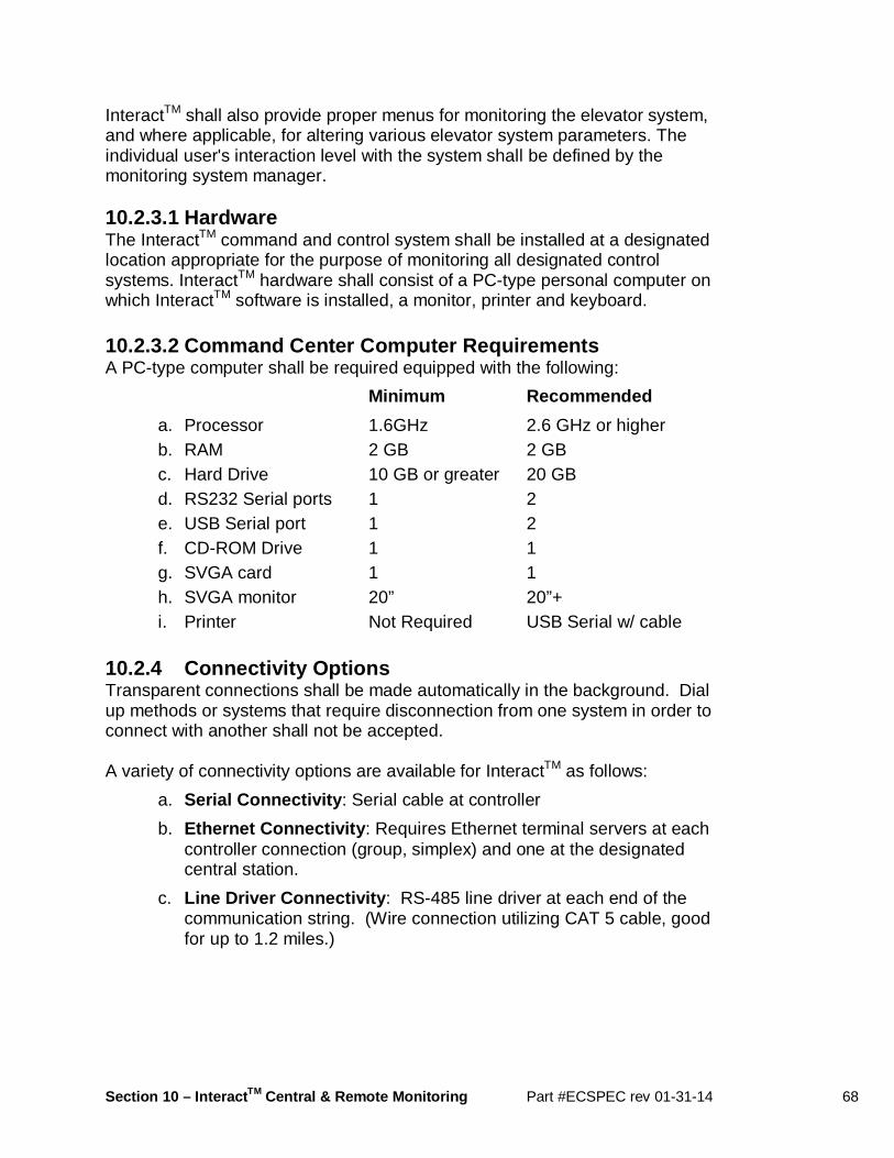
Section 10 – Interact TM Central & Remote Monitoring Part #ECSPEC rev 01-31-14 68
InteractTM shall also provide proper menus for monitoring the elevator system, and where applicable, for altering various elevator system parameters. The individual user's interaction level with the system shall be defined by the monitoring system manager. 10.2.3.1 Hardware The InteractTM command and control system shall be installed at a designated location appropriate for the purpose of monitoring all designated control systems. InteractTM hardware shall consist of a PC-type personal computer on which InteractTM software is installed, a monitor, printer and keyboard. 10.2.3.2 Command Center Computer Requirements A PC-type computer shall be required equipped with the following:
Minimum Recommended
a. Processor 1.6GHz 2.6 GHz or higher b. RAM 2 GB 2 GB c. Hard Drive 10 GB or greater 20 GB d. RS232 Serial ports 1 2 e. USB Serial port 1 2 f. CD-ROM Drive 1 1 g. SVGA card 1 1 h. SVGA monitor 20” 20”+ i. Printer Not Required USB Serial w/ cable
10.2.4 Connectivity Options Transparent connections shall be made automatically in the background. Dial up methods or systems that require disconnection from one system in order to connect with another shall not be accepted. A variety of connectivity options are available for InteractTM as follows:
a. Serial Connectivity : Serial cable at controller
b. Ethernet Connectivity : Requires Ethernet terminal servers at each controller connection (group, simplex) and one at the designated central station.
c. Line Driver Connectivity : RS-485 line driver at each end of the communication string. (Wire connection utilizing CAT 5 cable, good for up to 1.2 miles.)

Section 10 – Interact TM Central & Remote Monitoring Part #ECSPEC rev 01-31-14 69
10.2.5 Graphical User Interface The InteractTM system shall run under the Microsoft Windows® operating system. The user interface shall be based on the standard Windows interface and function similar to other Windows®' programs. 10.2.6 Monitoring and Diagnosis Screens When connected to an elevator system, InteractTM shall be capable of displaying various screens in real time to facilitate system monitoring and diagnosis. 10.2.7 Online Context-Sensitive Help The InteractTM system shall provide a complete and comprehensive online help system. A complete online support manual shall be imbedded in the monitoring system. A context sensitive help program shall provide users with assistance in understanding the various program functions. 10.2.8 Elevator System Summary The InteractTM system shall provide a screen which briefly describes the elevator system, including the job number, job name, number of cars, number of landings, number of openings per landing for each car, car labels, landing labels, fire service options, serial communication port definitions and other system options. The user shall be able to reprogram floor numbers and job names to match the actual building names. 10.2.9 Car Flags The InteractTM system shall display each car’s internally generated computer flags, complete call assignments, and allow the registration of calls on a single screen to facilitate performance analysis and problem diagnosis. 10.2.10 Graphical Hoistway Display The InteractTM system shall display a graphical representation of the elevator system hoistway such that the user can intuitively view movement of elevator cars within the hoistway and other information including, but not limited to the following:
a. Simulated hoistway and car configuration b. Individual elevator position c. Individual elevator car calls d. Individual elevator direction e. Individual elevator door position f. Individual elevator status of operation g. Individual elevator communication status h. Registered up and down hall calls i. Group system mode of operation

Section 10 – Interact TM Central & Remote Monitoring Part #ECSPEC rev 01-31-14 70
j. Assigned hall calls to individual elevator (G900 group only) k. Hall call wait time per registered hall call (G900 group only) l. Remote registration of car and hall calls (G900 group only)
10.2.11 System Parameters The InteractTM system shall display elevator system control and adjustment parameters for group operation (G900 group only) including, but not limited to the following:
a. Parking floors and their priorities b. Hall call priority times per landing c. Parking floor delay time d. Parking reassignment (shuffle) delay time e. Group mode of operation f. Parameters which define each mode of operation g. Parameters for lobby up peak operation h. Parameters for traffic identification i. Timed activation of programmed group configurations j. View and change individual car parameters k. Door dwell times l. Time out of service parameter m. Nudging time parameter n. Calculated car times (Not Adjustable): door opening time, door
closing time, through time, deceleration time 10.2.12 Emergency and/or Fault Notification In the unlikely event of an elevator shutdown, or any other defined system emergency condition, the InteractTM system shall recognize the presence of such condition/s and respond with notifications including, but not limited to:
a. On screen error message b. Printing an error report c. E-mailing an error report to one or multiple destinations
The variety of means shall be intuitively and flexibly selectable and configurable by the system user. 10.2.13 Analytical Toolset The InteractTM system shall support traffic and fault analysis by providing access to system performance and fault data selected by time, type of fault, etc to reveal underlying patters.

Section 10 – Interact TM Central & Remote Monitoring Part #ECSPEC rev 01-31-14 71
10.2.14 Standard and Custom Screen and Printed Repo rts The InteractTM system shall provide historical and performance reports which shall be easily sorted and selectable to focus on specific information of interest. In addition to an extensive library of the predefined reports, the InteractTM system shall be capable of generating user defined custom reports. All reports shall be graphically represented, and user preferences shall be easily set to format graph types, styles, display colors and even 3-D format representation. 10.2.15 Reportable Data The InteractTM system shall provide the ability to extract ranges of data and produce on screen and printable reports. Representations shall include both graphical and tabular options, where the user may specify time frame resolution in intervals measured in minutes, including but not limited to the following information:
a. Hall call, car call and miscellaneous reports b. Average wait time per time and direction by period c. Number of hall calls per time by period d. Group dispatching and car controller faults/events by date, time
and event description/status e. Emergency faults/events by specific event or category of events
by time period f. Hall call response in specified intervals (seconds) including call
responses within a particular interval g. Hall call distribution by date, time, direction, hallway and wait
time h. Hall call performance by floor, direction including number of
registered calls, average wait time, maximum wait time and minimum wait time
i. Number of hall calls per landing and direction by landing, direction, and time period
j. Average wait time per landing and direction by landing, direction, and time period
k. Number of hall calls answered per car for a specified time period. l. Percent of up and down hall calls by percentage, direction, and
time period m. Car call distribution by car, source floor, destination floor, door
(front/rear), travel time, and time period

Section 10 – Interact TM Central & Remote Monitoring Part #ECSPEC rev 01-31-14 72
n. Car call performance by car, average travel time, minimum travel time and maximum travel time, and by time period
o. Number of car calls per car by time period p. Number of car calls per landing by time period q. Average travel time per car by car, and by time period r. Average travel time between source and destination by time
period 10.2.16 Relational Database The InteractTM system shall be constructed and programmable to automatically collect data from all monitored elevator systems and update its database. The system shall provide multiple level of password protection for system use. All data collected from monitored elevator systems shall be stored in a relational database which shall facilitate limitless possible search methods and selection criteria for viewing and analyzing collected data. 10.3 General – Lift-Net Lift-Net provides comprehensive monitoring solutions that include elevators, escalators and moving walkways of diverse age and brand, including Elevator Controls. When a mix of equipment must be monitored within a single system, Lift-Net is the preferred choice. There is some tradeoff between the comprehensive amount of data available within the Interact system vs. the breadth of equipment that can be monitored using Lift-Net. 10.4 General – CampusView and Kings III Communicati ons The control system shall also have the capability to interface to the CampusView monitoring system, and also it shall directly interface to Kings III Comunications for 24-7 telephone monitoring capabilities.
Section 11 – Security Part #ECSPEC rev 01-31-14 73
Section 11 Security Overview EC Basic Security Elevator Controls Corporation is a highly regarded manufacturer of Non-proprietary, microprocessor-based elevator controls. Our equipment is designed and engineered using appropriate, proven technology… to ensure years of field reliability. Today’s environment has brought increased attention to security concerns. Regulation, restriction and control of vertical transportation within a building can be a critical component of total facility security programs intended to detect, defend and facilitate response to intrusion. EC Basic Security prevents unauthorized individuals from entering car calls and allows only authorized individuals to access restricted floors. Basic Interact Security with Display enhances EC Basic Security by providing the ability to activate or deactivate access restrictions from a machine room Display or remote system monitoring Display running InteractTM Monitoring software. Options include interfacing to various types of Card Reader Systems, Floor Key Lockout operation, and Anti-Terrorism Control. 11.0 General Elevator security options available for all Elevator Controls controllers include EC Basic Security using car call buttons and Interact Security with Display. 11.1 Specifications: Basic Car Call Button Secur ity OPTIONAL - EC Basic Security can be used to prevent unauthorized individuals from entering car calls and allows only authorized individuals to access restricted floors. Basic Security provides a means to prevent unauthorized registration of car calls by allowing access only to the floor/s for which an elevator passenger is authorized. Exiting from the elevator at designated lobby floors shall not be restricted. The EC Basic Security system shall allow access to any floor or combination of floors controlled by the elevator security system to be either unrestricted or restricted. A single input to the microcomputer system, such as a key switch, time clock, etc, shall place the system in secure mode.
Secure Mode shall have the effect of rendering all car call buttons inoperative except those for floors programmed to allow unrestricted access. Access to restricted floors shall be accomplished from any floor by entering a hall call. The arriving elevator car shall require that the destination floor be followed by

Section 11 – Security Part #ECSPEC rev 01-31-14 74
entry of an access code, using the standard car operating panel pushbuttons, in order to register a car call. If the code sequence has been entered correctly, the call destination lamp shall be illuminated and the call accepted. Without entry of the correct code, car call registration shall not be accepted. Multiple attempts shall be allowed. An optional restricted floor indicator can be illuminated to confirm that access to a restricted floor is being requested. The access authorization sequence shall start with the destination floor button, followed by entry of a code sequence of up to eight numbers. If a sequence does not match one contained in the security system data table, the memory shall automatically be cleared and the elevator passenger denied access. While in Secure Mode, elevators shall park at designated lobby floor/s to prevent parking at and subsequent unauthorized access to restricted floors. Emergency operations including Fire Service shall override security operation. 11.2 Specifications: Interact TM Security with Display Interact Security with Display enhances EC Basic Security by providing the ability to activate or deactivate access restrictions from a machine room Display or remote system monitoring Display running InteractTM Monitoring software. 11.2.1 Car Call Access OPTIONAL - Interact Security with Display shall allow either restricted or unrestricted access to any floor or floors controlled by the elevator security system. Field programmable floor security codes shall be required for access. The EC Interact Security system shall allow access to any floor or combination of floors controlled by the elevator security system to be either unrestricted or restricted. A single input to the microcomputer system, such as a key switch, display terminal or software timer table, shall place the system in Secure Mode.
While in Secure Mode, elevators shall park at designated lobby floor/s to prevent parking at and subsequent unauthorized access to restricted floors. Secure Mode shall have the effect of rendering all car call buttons inoperative except those for floors programmed to allow unrestricted access. Access to restricted floors shall be accomplished from any floor by entering a hall call. The arriving elevator car shall require that the destination floor be followed by entry of an access code, using the standard car operating panel pushbuttons, in order to register a car call.

Section 11 – Security Part #ECSPEC rev 01-31-14 75
If the code sequence has been entered correctly, the call destination lamp shall be illuminated and the call accepted. Without entry of the correct code, car call registration shall not be accepted. Multiple attempts shall be allowed. An optional restricted floor indicator can be illuminated to confirm that access to a restricted floor is being requested. The access authorization sequence shall start with the destination floor button, followed by entry of a code sequence of up to eight numbers. If a sequence does not match one contained in the security system data table, the memory shall automatically be cleared and the elevator passenger denied access. While in Secure Mode, elevators shall park at designated lobby floor/s to prevent parking at and subsequent unauthorized access to restricted floors. Emergency operations including Fire Service shall override security operation. 11.2.2 The Interact Security Car or Hall Call Lock out OPTIONAL - Interact Security shall allow the user to completely disable a car or hall call button from within the Interact Security system as if a Floor Key Lockout had been activated. Emergency operations including Fire Service shall override all modes of Interact Security operation. 11.3 Card Reader Interface OPTIONAL - A Card Reader Interface shall be provided. The card reader vendor shall provide a dry contact output which shall be used to restrict registration of calls. Such contact/s shall be provided per opening, per call or for groups of calls and openings as required. Emergency operations including Fire Service shall override Card Reader Lockout mode. 11.4 Floor Key Lockout OPTIONAL - A floor key lockout interface shall be provided to disable registration of calls. Floor Key Lockout function shall be provided per opening, per call or for groups of calls and openings as required. Emergency operations including Fire Service shall override Floor Key Lockout mode. 11.5 Anti-Terrorism Control OPTIONAL - Anti-Terrorism Control is intended to work hand-in-hand with other means of detection and intervention. Anti-Terrorism operation shall be

Section 11 – Security Part #ECSPEC rev 01-31-14 76
enabled upon activation of an Anti-Terrorism Switch located either at the lobby, lobby console or at a remote location. When an Anti-Terrorism Switch is activated, if the elevator is already at the lobby with doors closed, the doors shall remain closed. If the elevator is in motion traveling away from lobby, the elevator shall stop at the next available floor without opening the doors, and return non-stop to the lobby where doors shall open. Once exiting passengers have vacated the elevator, the doors shall close.
If the elevator is in motion traveling toward the lobby, the elevator shall return non-stop to the lobby where doors shall open. Once exiting passengers have vacated the elevator, the doors shall close. Anti-Terrorism Control circuitry shall operate with simplex, duplex and/or group controls. Any floor/s can be designated as a lobby floor. 11.6 Custom Security Functions OPTIONAL - A wide range of customized security functions can be developed to meet complex specifications. Inquire in confidence about unique and highly customized security options to satisfy specific security requirements.
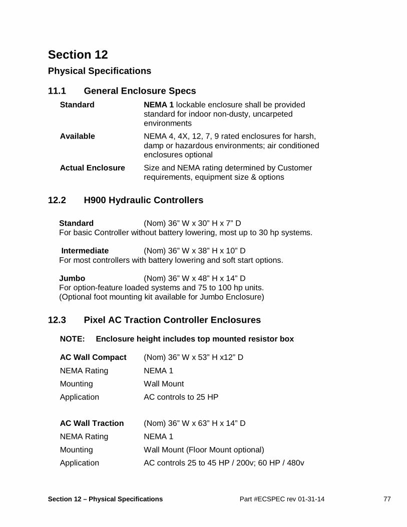
Section 12 – Physical Specifications Part #ECSPEC rev 01-31-14 77
Section 12 Physical Specifications 11.1 General Enclosure Specs
Standard NEMA 1 lockable enclosure shall be provided standard for indoor non-dusty, uncarpeted environments
Available NEMA 4, 4X, 12, 7, 9 rated enclosures for harsh, damp or hazardous environments; air conditioned enclosures optional
Actual Enclosure Size and NEMA rating determined by Customer requirements, equipment size & options
12.2 H900 Hydraulic Controllers Standard (Nom) 36” W x 30” H x 7” D For basic Controller without battery lowering, most up to 30 hp systems. Intermediate (Nom) 36” W x 38” H x 10” D For most controllers with battery lowering and soft start options. Jumbo (Nom) 36” W x 48” H x 14” D For option-feature loaded systems and 75 to 100 hp units. (Optional foot mounting kit available for Jumbo Enclosure)
12.3 Pixel AC Traction Controller Enclosures NOTE: Enclosure height includes top mounted resis tor box
AC Wall Compact (Nom) 36” W x 53” H x12” D
NEMA Rating NEMA 1
Mounting Wall Mount
Application AC controls to 25 HP
AC Wall Traction (Nom) 36” W x 63” H x 14” D
NEMA Rating NEMA 1
Mounting Wall Mount (Floor Mount optional)
Application AC controls 25 to 45 HP / 200v; 60 HP / 480v
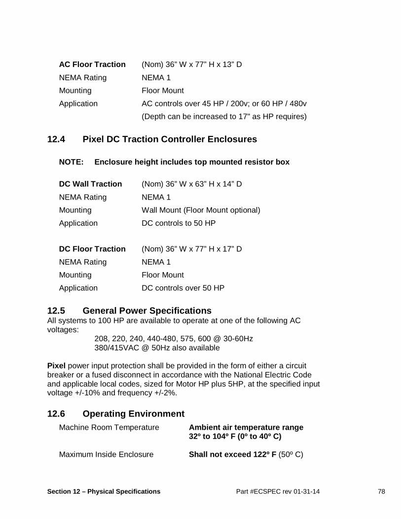
Section 12 – Physical Specifications Part #ECSPEC rev 01-31-14 78
AC Floor Traction (Nom) 36” W x 77” H x 13” D
NEMA Rating NEMA 1
Mounting Floor Mount
Application AC controls over 45 HP / 200v; or 60 HP / 480v
(Depth can be increased to 17" as HP requires)
12.4 Pixel DC Traction Controller Enclosures
NOTE: Enclosure height includes top mounted resis tor box
DC Wall Traction (Nom) 36” W x 63” H x 14” D
NEMA Rating NEMA 1
Mounting Wall Mount (Floor Mount optional)
Application DC controls to 50 HP
DC Floor Traction (Nom) 36” W x 77” H x 17” D
NEMA Rating NEMA 1
Mounting Floor Mount
Application DC controls over 50 HP
12.5 General Power Specifications All systems to 100 HP are available to operate at one of the following AC voltages: 208, 220, 240, 440-480, 575, 600 @ 30-60Hz 380/415VAC @ 50Hz also available Pixel power input protection shall be provided in the form of either a circuit breaker or a fused disconnect in accordance with the National Electric Code and applicable local codes, sized for Motor HP plus 5HP, at the specified input voltage +/-10% and frequency +/-2%. 12.6 Operating Environment
Machine Room Temperature Ambient air temperature range 32º to 104º F (0º to 40º C) Maximum Inside Enclosure Shall not exceed 122º F (50º C)

Section 12 – Physical Specifications Part #ECSPEC rev 01-31-14 79
Operating Temperature 32º F to 122º F (0º C to 50º C) Storage Temperature -22º F to 150º F (-30º C to 65º C) Humidity 10% to 90% non-condensing Altitude Up to 7500 feet (2286 m)