Embed Size (px)
Citation preview

EC-2™ Installation GuideProduct Modification Warning ............................................................................................ 3FCC Information ................................................................................................................... 3Important Safety Information .............................................................................................. 4Warranty Information .......................................................................................................... 4Caution and Warning Symbols ............................................................................................ 6
Introduction How to Use this Guide ......................................................................................................... 7Planning the Installation ...................................................................................................... 7
Unpacking the EC-2™ Fixture ...................................................................................... 8Saving the Shipping Materials ..................................................................................... 8Identifying EC-2™ Components .................................................................................... 8
Circuit Breaker Protection ................................................................................................... 9DMX 512 Data Cable Specification ..................................................................................... 9Wire Routing ......................................................................................................................... 9
EC-2 Fixture Installation Permanent Mounting ......................................................................................................... 10
Securing the Fixture to the Prepared Foundation .................................................... 11Setting/Changing the Fixture Voltage ............................................................................... 11EC-2™ Wiring Instructions ................................................................................................. 13
Connecting Power Wiring in Standalone Installation .............................................. 13DMX 512 Data Wiring in a Standalone Installation ................................................. 14
Linking Fixtures ................................................................................................................ 15Connecting Power Wiring in a Linked Installation ................................................... 15DMX 512 Data Wiring in a Linked Installation ......................................................... 16Terminating the Data Link .......................................................................................... 18
Testing EC-2 Installation Before Powering Up ........................................................................................................... 19
Check Main Power Wiring .......................................................................................... 19Check DMX 512 Data Wiring ..................................................................................... 19Check DMX 512 Network Wiring .............................................................................. 19
Powering Up Fixture .......................................................................................................... 20Installation Checklist .......................................................................................................... 20
EC-2™ Installation Guide Page 1

Declaration of Conformityaccording to ISO/IEC Guide 22 and EN45104
Manufacturer’s name: High End Systems, Inc.Manufacturer’s address: 2105 Gracy Farms Lane
Austin, Texas 78758 USA
Distributor’s name: High End Systems, Inc.Distributor’s address: 2105 Gracy Farms Lane
Austin, Texas 78758 USA
Declares that the product
Product Name: EC-2Product Number: EC-2Product Options: All
conforms to the following EEC directives:73/23/EEC, as amended by 93/68/EEC89/336/EEC, as amended by 92/31/EEC and 93/68/EEC
Equipment referred to in this declaration of conformity was first manufactured in compliance with the fol-lowing standards in 2000:
Safety: EN 60598-1 : 1997EN 60598-2-17 ; 1989A1-A3 : 1993
EMC: EN 55022, 1987 Class A ITEEN61000-4-2: 1995 Level 2/3 (2/3kV)EN61000-4-3: 1995 Level 2 (3V/m)ENV50204:1996: Level 2 (3V/m)EN61000-4-4: 1995 Level 2 (1/.5kV)EN61000-4-5: 1995 Level 3 (2/1kV)EN61000-4-6: 1996 Level 2 (3Vrms)EN61000-4-11:1994IEC 1000-3-2/EN 61000-3-2
USA, Sunday, January 07, 2001Kenneth Stuart Hansen, Compliance Engineer
Page 2 EC-2™ Installation Guide

Product Modification WarningHigh End Systems’ products are designed and manufactured to meet the requirements of United States and International safety regulations. Modifications to the product could affect safety and render the product non-compliant to relevant safety standards.
Mise En Garde Contre La Modification Du Produit
Les produits High End Systems sont conçus et fabriqués conformément aux exigences des règlements internationaux de sécurité. Toute modification du produit peut entraîner sa non conformité aux normes de sécurité en vigueur.
Produktmodifikationswarnung
Design und Herstellung von High End Systems entsprechen den Anforderungen der U.S. Amerikanischen und internationalen Sicherheitsvorschriften. Abänderungen dieses Produktes können dessen Sicherheit beeinträchtigen und unter Umständen gegen die diesbezüglichen Sicherheitsnormen verstoßen.
Avvertenza Sulla Modifica Del Prodotto
I prodotti di High End Systems sono stati progettati e fabbricati per soddisfare i requisiti delle normative di sicurezza statunitensi ed internazionali. Qualsiasi modifica al prodotto potrebbe pregiudicare la sicurezza e rendere il prodotto non conforme agli standard di sicurezza pertinenti.
Advertencia De Modificación Del Producto
Los productos de High End Systems están diseñados y fabricados para cumplir los requisitos de las reglamentaciones de seguridad de los Estados Unidos e internacionales. Las modificaciones al producto podrían afectar la seguridad y dejar al producto fuera de conformidad con las normas de seguridad relevantes.
FCC InformationThis equipment has been tested and found to comply with the limits for a Class A digital device, pursuant to part 15 of the FCC rules. These limits are designed to provide reasonable protection against harmful interference when the equipment is operated in a commercial environment. This equipment generates, uses, and can radiate radio frequency energy and, if not installed and used in accordance with the instruction manual, may cause harmful interference to radio communications. Operation of this equipment in a residential area is likely to cause harmful interference, in which case the user will be required to correct the interference at his own expense.
EC-2™ Installation Guide Page 3

Important Safety InformationInstructions pertaining to continued protection against fire, electric shock, exposure to excessive ultraviolet (UV) radiation, and injury to persons are found in Appendix B of the EC-2 User Manual that was shipped with your fixture.
Please read all instructions prior to assembling, mounting, and operating this equipment.
Important: Informations De Sécurité
Les instructions se rapportant à la protection permanente contre les incendies, l’électrocution, l’exposition à un rayonnement ultraviolet (UV) excessif et aux blessures corporelles se trouvent dans l’Annexe B.
Veuillez lire toutes les instructions avant d’assembler, de monter ou d’utiliser cet équipement.
Wichtige Sicherheitshinweise
Sicherheitsanleitungen zum Schutz gegen Feuer, elektrischen Schlag, übermäßige UV-Strahlung und Verletzung von Personen finden Sie in Anhang B.
Vor der Montage, dem Zusammenbau und der Intbetriebnahme dieses Geräts alle Anleitungen sorgfältig durchlesen.
Informazioni Importanti Di Sicurezza
Le istruzioni sulla protezione da incendi, folgorazione, esposizione eccessiva a raggi ultravioletti (UV) e infortuni sono contenute nell’appendice B.
Si prega di leggere tutte le istruzioni prima di assemblare, montare e azionare l’apparecchiatura.
Informacion Importante De Seguridad
En el Apéndice B se encuentran instrucciones sobre protección continua contra incendios, descarga eléctrica, exposición excesiva a radiación ultravioleta (UV) y lesiones personales.
Lea, por favor, todas las instrucciones antes del ensamblaje, montaje y operación de este equipo.
Warranty InformationLimited WarrantyUnless otherwise stated, your product is covered by a two year parts and labor limited warranty. Dichroic filters are not guaranteed against breakage or scratches to coating. It is the owner’s responsibility to furnish receipts or invoices for verification of purchase, date, and dealer or distributor. If purchase date cannot be provided, date of manufacture will be used to determine warranty period.
Page 4 EC-2™ Installation Guide

Returning an Item Under Warranty for RepairIt is necessary to obtain a Return Material Authorization (RMA) number from your dealer or point of purchase BEFORE any units are returned for repair. The manufacturer will make the final determination as to whether or not the unit is covered by warranty. Lamps are covered by the lamp manufacturer’s warranty.
Any Product unit or parts returned to High End Systems must be packaged in a suitable manner to ensure the protection of such Product unit or parts, and such package shall be clearly and prominently marked to indicate that the package contains returned Product units or parts and with an RMA number. Accompany all returned Product units or parts with a written explanation of the alleged problem or malfunction. Ship returned Product units or parts to: 2105 Gracy Farms Lane, Austin, TX 78758 USA.
Note: Freight Damage Claims are invalid for fixtures shipped in non-factory boxes and packing materials.
FreightAll shipping will be paid by the purchaser. Items under warranty shall have return shipping paid by the manufacturer only in the Continental United States. Under no circumstances will freight collect shipments be accepted. Prepaid shipping does not include rush expediting such as air freight. Air freight can be sent customer collect in the Continental United States.
REPAIR OR REPLACEMENT AS PROVIDED FOR UNDER THIS WARRANTY IS THE EXCLUSIVE REMEDY OF THE CONSUMER. HIGH END SYSTEMS, INC. MAKES NO WARRANTIES, EXPRESS OR IMPLIED, WITH RESPECT TO ANY PRODUCT, AND HIGH END SPECIFICALLY DISCLAIMS ANY WARRANTY OF MERCHANTABILITY OR FITNESS FOR A PARTICULAR PURPOSE. HIGH END SHALL NOT BE LIABLE FOR ANY INDIRECT, INCIDENTAL OR CONSEQUENTIAL DAMAGE, INCLUDING LOST PROFITS, SUSTAINED OR INCURRED IN CONNECTION WITH ANY PRODUCT OR CAUSED BY PRODUCT DEFECTS OR THE PARTIAL OR TOTAL FAILURE OF ANY PRODUCT REGARDLESS OF THE FORM OF ACTION, WHETHER IN CONTRACT, TORT (INCLUDING NEGLIGENCE), STRICT LIABILITY OR OTHERWISE, AND WHETHER OR NOT SUCH DAMAGE WAS FORESEEN OR UNFORESEEN.
Warranty is void if the product is misused, damaged, modified in any way, or for unauthorized repairs or parts. This warranty gives you specific legal rights, and you may also have other rights which vary from state to state.
EC-2™ Installation Guide Page 5

Caution and Warning SymbolsThe following international symbols appear in margins throughout this manual to highlight caution and warning messages:
CautionsNot heeding these messages could result in personal injury and/or damage to equipment.
Caution: This symbol indicates caution messages.
Hot Surface:This symbol indicates a hot surface.
WarningsNot heeding these messages could result in serious personal injury.
Warning: This symbol indicates high voltage warning messages.
Fire Hazard:This symbol indicates that a fire hazard is present.
Eye Protection:This symbol indicates that eye protection is required.
Explosion:This symbol indicates an explosion hazard.
Minimum This symbol indicates the minimum distance to a lightedDistance: object, which in this case is 1 meter.
Not Suitable for mounting directly on normally flammable surfaces.
Page 6 EC-2™ Installation Guide

IntroductionHow to Use this GuideThis document provides instructions for installing the EC-2 fixture and is organized into three sections:
1. Introduction describes general requirements for installation.
2. EC-2 Fixture Installation includes all directions for mounting, wiring power and data lines and setting the voltage.
3. Testing the EC-2 Installation provides information on powering up, focusing the fixture, testing, and a checklist to complete the installation.
The EC-2 fixture must be installed by suitably qualified personnel (such as an electrician) in accordance with local and national building and electric codes. These instructions are intended for electricians and/or building contractors already familiar with electrical wiring and construction.
Planning the InstallationThe EC-2 fixture is an ETL/ETLC recognized component when the following conditions of acceptability are met:
1. The EC-2 fixture must be installed in accordance with local and national building and electrical codes.
2. The EC-2 fixture must be mounted on a site that provides adequate drainage so that the fixture is never immersed in standing water.
3. The EC-2 fixture must be properly secured with recommended mounting hardware (see the section titled “Permanent Mounting” on page 10).
Heed the following warnings to guard against personal injury and damage to the fixture:
Caution: 1)Do not mount on a flammable surface.
2)Maintain a minimum distance of 1 m (3.28 ft.) from combustible materials.
3)Maintain a minimum distance of 1 m (3.28 ft.) from lighted object. This means the fixture must be positioned at least 1 meter awayfrom the object it is illuminating.
EC-2™ Installation Guide Page 7

Unpacking the EC-2™ FixtureCarefully unpack the carton and inspect the contents for damage. If any of the items in the following list are missing or damaged, notify both the shipping agent and your sales agent immediately.
• EC-2™ fixture
• EC-2™ User Manual
• EC-2™ Installation Guide
• Package containing: —One 5-pin Data connector—One 2-pin Power connector—One 120Ω termination resistor—Two ferrite rings—One tie wrap
• Mounting template
Saving the Shipping MaterialsDo not discard the shipping carton and packing materials. The carton and packing materials are specifically designed to protect the product during transport.
High End Systems assumes no responsibility for products that have been damaged during transport. Therefore, you should return a product for repair in its original shipping carton and packing materials.
Note: Before sending anything to the factory, call your High End Systems dealer/distributor for a RMA (Return Material Authorization) number. The factory cannot accept any goods shipped without a RMA number.
Identifying EC-2™ Components
Lamp Cap
Power conduit connection
Data conduit connection
Logic board
Access panel to logic board
Yoke tilt screwsBack fixture housing
Front fixture housing
Figure 1 EC-2 Fixture Components
Page 8 EC-2™ Installation Guide

Circuit Breaker ProtectionInstall an electrical connection (junction box) no more than four feet away from the foundation. A single junction box is acceptable only if it has a barrier to separate data and power wiring. High End Systems, Inc. recommends that the mains power supply to EC-2 be ground fault protected for added safety.
Wiring should be sized as per your local and national electrical codes and should include 20A maximum branch circuit protection.
A guideline for determining the number of fixtures which can be powered per breaker is shown in Table 1 .
DMX 512 Data Cable SpecificationBelden® 1419A or equivalent (meets specifications for EIA RS-485 applications) with the following characteristics:
• Two twisted pairs (4 conductors) plus a shield
• maximum capacitance between paired conductors — 30 pF/ft.
• maximum capacitance between conductor and shield — 55 pF/ft.
• maximum resistance of 20Ω / 1000 ft.
• nominal impedance 120Ω
Wire Routing• The EC-2 fixture should be connected to power and data supplies with metal-lined,
1/2in. listed seal-tight conduit.
• Data and power conduit connect at the back of the fixture, (see Figure 1 on page 8).
• Data and power wiring must always be run in separate conduit.
Power Supply Fixtures per 20A Breaker
120V or less 2
230V 4
277V 5
Table 1 Guideline for number of fixtures per breaker
Pin Function Color Code
Pin 1 Common Shield
Pin 2 DMX Data – White/Blue Stripe
Pin 3 DMX Data + Blue/White Stripe
Pin 4 Aux Data – White/Orange Stripe
Pin 5 Aux Data + Orange/White Stripe
EC-2™ Installation Guide Page 9

EC-2 Fixture InstallationPermanent MountingThe EC-2 fixture is designed for surface mounting on the ground or a wall. Ceiling and truss-mounting are not recommended using the EC-2 fixture’s installed yoke.
Note: Certain orientations in ceiling mounting will make the fixture’s logic board susceptible to heat damage since the EC-2 has no fan and uses only natural convection for cooling.
High End Systems, Inc. cannot make specific recommendations for your particular light design or venue. Because there are a variety of conceivable lighting designs, you should consider the procedure below as a suggested guideline only. Consult with a structural engineer or other professional familiar with national and local building codes for your unique application.
To mount the EC-2 fixture:
1. Construct a foundation of a suitable non-flammable material (concrete, steel, etc.). If mounted on the ground or floor, the founda-tion must be able to support the weight of EC-2 (see Table 2). If mounted on the wall, the foundation must be able to support the weight of EC-2 plus the pull-out force of each mounting stud.
The foundation can be any shape that creates an adequate base for the fixture. See Table 2 for EC-2 dimensions. Allow clearance on all sides of the fixture for lamp replacement and service access.
2. Use template included with the fixture to locate position of four mounting studs. Locate studs (or anchors) as shown in Figure 2 to allow the full pan range.
3. Install the four 3/8 in. mounting studs in the foundation so that the threaded ends extend above the surface at least 1 in. (25mm).
Table 2 Mounting Specifications
EC-2 Dimensions
20.27 in. (514.9 mm) H × 10 in. (254 mm) W ×16.72 in. (424.7 mm) D.
EC-2 Weight 46 lbs. (20.9 kg)
Mounting Studs
For floor/ground mounting: Four 3/8in. UNC threaded steel studs or equivalent concrete anchors.
For wall mounting: Four 3/8 in. UNC galvanized mounting studs of stainless steel (or material with equivalent corrosion protection.)
Pull-out force For each stud in wall m ounting: 800 lbs. (363 kg)
Access clearance 2ft. (.6 m)
Fire safety clearance
3ft. (1m) from flammable surface
Figure 2 Mounting template
Location formounting
studs
Page 10 EC-2™ Installation Guide
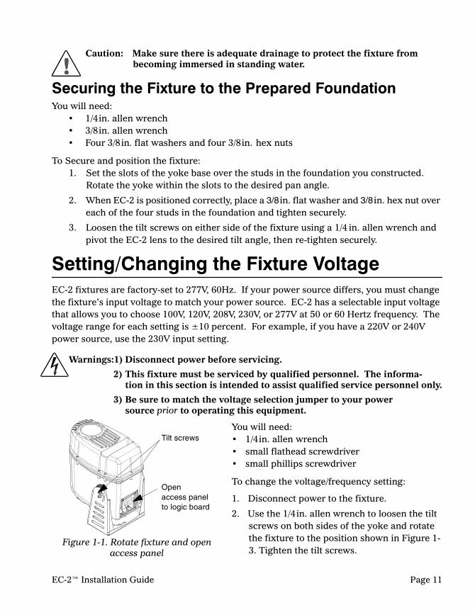
Caution: Make sure there is adequate drainage to protect the fixture from becoming immersed in standing water.
Securing the Fixture to the Prepared FoundationYou will need:
• 1/4in. allen wrench• 3/8in. allen wrench• Four 3/8in. flat washers and four 3/8in. hex nuts
To Secure and position the fixture:1. Set the slots of the yoke base over the studs in the foundation you constructed.
Rotate the yoke within the slots to the desired pan angle.
2. When EC-2 is positioned correctly, place a 3/8in. flat washer and 3/8in. hex nut over each of the four studs in the foundation and tighten securely.
3. Loosen the tilt screws on either side of the fixture using a 1/4 in. allen wrench and pivot the EC-2 lens to the desired tilt angle, then re-tighten securely.
Setting/Changing the Fixture VoltageEC-2 fixtures are factory-set to 277V, 60Hz. If your power source differs, you must change the fixture’s input voltage to match your power source. EC-2 has a selectable input voltage that allows you to choose 100V, 120V, 208V, 230V, or 277V at 50 or 60 Hertz frequency. The voltage range for each setting is ±10 percent. For example, if you have a 220V or 240V power source, use the 230V input setting.
Warnings:1) Disconnect power before servicing.
2) This fixture must be serviced by qualified personnel. The informa-tion in this section is intended to assist qualified service personnel only.
3) Be sure to match the voltage selection jumper to your powersource prior to operating this equipment.
You will need:• 1/4in. allen wrench• small flathead screwdriver• small phillips screwdriver
To change the voltage/frequency setting:
1. Disconnect power to the fixture.
2. Use the 1/4in. allen wrench to loosen the tilt screws on both sides of the yoke and rotate the fixture to the position shown in Figure 1-3. Tighten the tilt screws.
Figure 1-1. Rotate fixture and open access panel
Tilt screws
Open access panel to logic board
EC-2™ Installation Guide Page 11

3. Use small, flathead screwdriver to loosen the access panel retaining screws and remove the access panel.
4. Locate the voltage/frequency jumpers on the logic board (see Figure 4).
5. To move a jumper, loosen the screw that secures the jumper end to the voltage or frequency contact.
6. Remove the jumper end and re-insert it behind the screw of the desired voltage or frequency contact (see Figure 5). After you move the jumper, tighten its corresponding screw to secure the jumper to the pin.
7. After changing the voltage and/or the frequency jumpers check that all the terminal screws are tightened securely.
8. Re-attach the access panel. Tighten the panel screws to a torque setting between 3–4 ft.lb. (4–5 Nm) to ensure a weather-tight seal.
Figure 4. Logic Board
5 4 3 2 1 3 2 1
Frequency/Voltage- select jumper block
Frequency Jumper
Voltage Jumper
Figure 5. Set jumpers to correct frequency and/or voltage
60Hz 50Hz 277V 230V 208V 120V 100V
Page 12 EC-2™ Installation Guide

EC-2™ Wiring InstructionsThe EC-2 fixture can be permanently wired either in a standalone application or linked with other fixtures. If you are linking the EC-2 fixture with other fixtures, go to “Linking Fixtures”, page 15 for wiring instructions.
After completing power and data wiring, check that the access panel gasket is in place and reattach the access panel securely to the fixture to ensure a watertight seal.
Connecting Power Wiring in Standalone Installation1. Run 1/2in. flexible, metal-lined, sealtight con-
duit from power source to fixture. Data and power cable must be run in separate conduit.
2. Attach conduit (see “Wire Routing”, page 9 for specifications) to fixture at power connection, see Figure 6.
3. Tilt fixture and open access panel to logic board as described in “Setting/Changing the Fixture Voltage”, page 11.
4. Pull power supply cable through conduit into fixture. Pull adequate cable to allow easy connection to the board.
5. Strip 3 in. of the cable jacket from the power cable (if applicable).
6. Strip 1/4 in. insulation from the end of each wire.
Note: Figure 7 shows the power connection process described in steps 7–10.
7. Loosen the ground screw and insert the ground wire behind it. Tighten the screw.
8. Loosen the screws in the 2-position power connector that was shipped with your fixture.
9. Insert the neutral wire into pin 1 and the line wire into pin 2. Tighten the screws.
10. Plug connector into header on logic board.
Figure 6 Power and Data connections
DataPower
Figure 7 Wiring to power connector and ground
2 1
GND
5 4 3 2
POWER
NEUTRAL LINE
EC-2™ Installation Guide Page 13

DMX 512 Data Wiring in a Standalone InstallationData cabling typically runs from an installed XLR wall mount to the fixture’s data connector. See “DMX 512 Data Cable Specification” on page 9 for cable specifications. Pin one is the common (cable shield), pin two is the data complement (negative), pin three is the data true (positive), and pins four and five are not used, but they allow a secondary data link to pass through the fixture.
You should test the cable with a voltage/ohm meter (VOM) to verify correct polarity and to make sure that the negative and positive pins are not grounded or shorted to the shield or to each other.
Caution: Do not connect anything to the ground lug on the XLR connectors. Do not connect or allow contact between the common (cable shield) and the fixture’s chassis ground. Grounding the common could cause a ground loop and/or erratic behavior.
1. Run conduit separate from power supply from the XLR wall panel to the data connection of the fixture, (see Figure 6 on page 13).
2. Tilt fixture and open access panel to logic board as described in “Setting/Changing the Fixture Voltage”, page 11.
3. Bring data cable through conduit into fixture. Pull enough cable to allow connection to the board and reduce strain to the wires during connection.
4. Slip one of the ferrite rings that was shipped with your fixture over the data cable and wire-tie it 4in. (100mm) back from the end.
5. Strip 3in. of the cable jacket from the end of the cable.
6. Cover all bare shield wires with 1/16 in. heat shrink.
7. Strip 1/4 in. insulation from the end of each wire.
Note: Figure 8 shows the data line connection described in steps 8–10.
8. Loosen the screws in the 5-position data connector that was shipped with your fixture.
9. Insert the shielded wire in pin 1 and the data wires as shown in the drawing.
10. Terminate the EC-2 by inserting the 120Ω resistor shipped with your fixture between pins 2 and 3 of the data connector.
1 2
5 4 2 1 3
(DRAIN)
DATA SHIELD
DMX DATA (pair one)
AUX DATA (pair two)
Termination Resistor
Figure 8 Data wiring and termination
Ferrite Ring
Wire Tie
Page 14 EC-2™ Installation Guide
11. Plug connector into logic board data header.
12. After checking gasket, re-attach the access panel. Tighten the panel screws to a torque setting between 3–4 ft.lb. (4–5 Nm) to ensure a weather-tight seal.
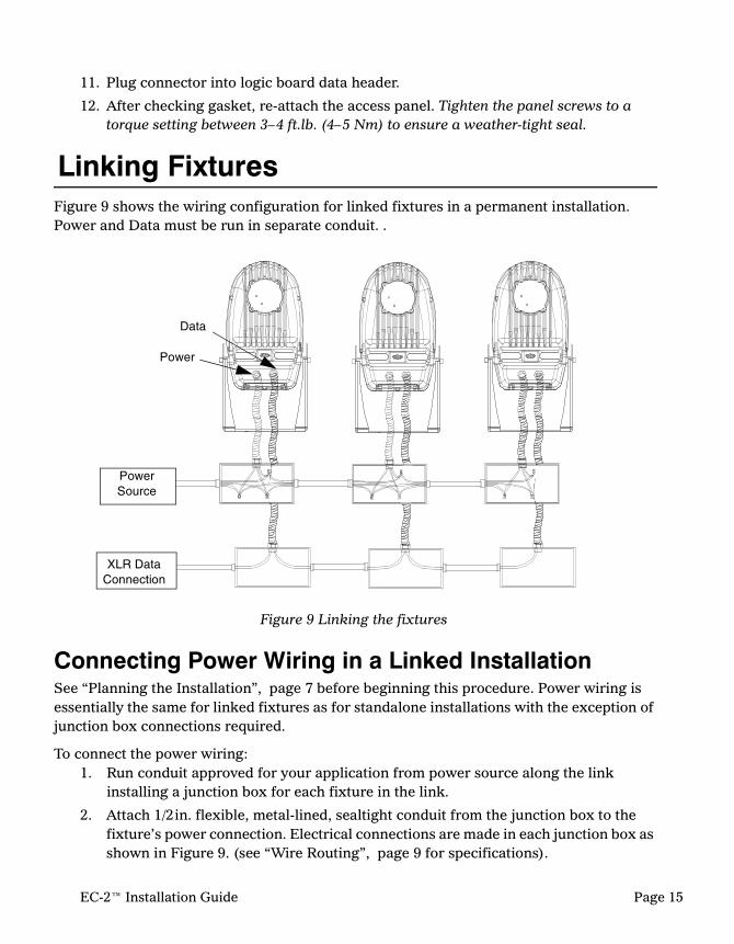
Linking FixturesFigure 9 shows the wiring configuration for linked fixtures in a permanent installation. Power and Data must be run in separate conduit. .
Connecting Power Wiring in a Linked InstallationSee “Planning the Installation”, page 7 before beginning this procedure. Power wiring is essentially the same for linked fixtures as for standalone installations with the exception of junction box connections required.
To connect the power wiring:1. Run conduit approved for your application from power source along the link
installing a junction box for each fixture in the link.
2. Attach 1/2in. flexible, metal-lined, sealtight conduit from the junction box to the fixture’s power connection. Electrical connections are made in each junction box as shown in Figure 9. (see “Wire Routing”, page 9 for specifications).
XLR Data Connection
Power Source
Figure 9 Linking the fixtures
Data
Power
EC-2™ Installation Guide Page 15

3. Tilt fixture and open access panel to logic board as described in “Setting/Changing the Fixture Voltage”, page 11.
4. Pull power supply wires through conduit into fixture. Pull enough wire to allow connection to the board.
5. Strip 3 in. of the cable jacket from the power cable (if applicable).
6. Strip 1/4 in. insulation from the end of each wire.
Note: Figure 10 shows the power connection described in steps 7–10.
7. Loosen the ground screw and insert the ground wire behind it. Tighten the screw.
8. Loosen the screws in the 2-position power connector that was shipped with your fixture.
9. Insert the neutral wire into pin 1 and the line wire into pin 2. Tighten the screws.
10. Plug connector into header on logic board.
DMX 512 Data Wiring in a Linked InstallationData cabling typically runs from an installed XLR wall mount to each fixture’s data connector in a daisy chain* and terminates with a resistor at the last fixture in the link.
*Note: A daisy chain is a connection in series, from the XLR wall connection to the data connector of the first fixture; then, from the data connector of the first fixture to the input of the second fixture, and so on.
See “DMX 512 Data Cable Specification” on page 9 for cable specifications. Pin one is the common (cable shield), pin two is the data complement (negative), pin three is the data true (positive), and pins four and five are not used, but they allow a secondary data link to pass through the fixture.
You should test each cable with a voltage/ohm meter (VOM) to verify correct polarity and to make sure that the negative and positive pins are not grounded or shorted to the shield or to each other.
Caution: Do not connect anything to the ground lug on the XLR connectors. Do not connect or allow contact between the common (cable shield) and the fixture’s chassis ground. Grounding the common could cause a ground loop and/or erratic behavior
Figure 10 Wiring to power connector and ground
2 1
GND
5 4 3 2
POWER
NEUTRAL LINE
Page 16 EC-2™ Installation Guide

To Connect DMX 512 data wiring in a link:
1. Run data conduit separate from power supply conduit from the XLR wall panel along the link. Install a junction box for each fixture. Run flexible conduit from each junction box to the data connection of its designated fixture, see Figure 6 on page 13.
2. Pull data cable from the XLR wall panel to the first fixture through its junction box.
3. Pull separate cables between each fixture and the next fixture on the link. Do not connect cabling in the junction box. Data connections must be made in the fixture’s connector.
4. Tilt fixture and open access panel to logic board as described in “Setting/Changing the Fixture Voltage”, page 11.
Note: Figure 11 shows the data wiring described in steps 5–14.
5. Bring data cable through conduit into fixture. Pull cable to allow connection to the board and reduce strain to the wires during connection.
6. Slip a ferrite ring that was shipped with your fixture over each data cable.
7. Strip 3 in. of the cable jacket from the end of the cable.
8. Cover all bare shield wires with 1/16in. heat shrink.
9. Join the two cables with heat shrink.
10. Place a wire tie 4 in. back on the cable in front of the ferrite rings to keep them from sliding forward.
11. Strip 1/4 in. insulation from the end of each wire.
12. Twist the end of each wire to the matching color of the data wire coming from the next fixture on the link.
13. Loosen the screws in the 5-position data connector that was shipped with your fixture.
14. Insert the shielded wire in pin 1 and the twisted pairs of data wire as shown in the drawing.
1 2
5 4 2 1 3
(DRAIN)
DATA SHIELD
DMX DATA (pair one)
AUX DATA (pair two)
Figure 11 Connecting the DMX 512 data wiring in a linked EC-2 fixture.
Wire Tie
Ferrite rings
Heat shrink
EC-2™ Installation Guide Page 17

Terminating the Data Link15. In a link, only the last fixture is terminated.
Terminate the last fixture on the link by inserting the resistor shipped with your fixture between pins 2 and 3 in the data connector.
16. Plug connector into logic board data header.
17. After checking gasket, re-attach the access panel. Tighten the panel screws to a torque setting between 3–4 ft.lb. (4–5 Nm) to ensure a weather-tight seal.
Note: Controllers, serial data distributors, data line optoisolators, and any fixtures using the RS-422 DMX standard of serial communications (including Dataflash® AF1000 xenon strobes, and Intellabeam® fixtures) block software uploads, crossloads or TalkBack™ fixture configuration on a link. Therefore, make sure you put all of these devices after the EC-2 fixtures on the link.
Figure 12 Terminating the link
5 4 3 2 1 shield
white/blueorange/white
white/orange blue/white
120 ohm resistor
Page 18 EC-2™ Installation Guide

Testing EC-2 InstallationBefore Powering Up
Warning: Power must be turned OFF when you perform this procedure.
1. Clean out dust, metal scraps or other debris near the logic board.
2. Check for loose connections, bare wires or damaged insulation.
Check Main Power WiringCheck resistance between phases, neutral and ground with a digital voltmeter (DVM) at the point of the fixture:
• Phase to Ground; resistance should be 10MΩ Ω Ω Ω or higher• Neutral to Ground; resistance should be approximately 0ΩΩΩΩ• Phase to Neutral; resistance should be approximately 1ΩΩΩΩ.
Check DMX 512 Data WiringIf you have installed the EC-2 fixture in a link with other fixtures, perform the following checks on cable at any of the fixtures on the link.
With the DMX512 connection off:
• Pin 3 (Data+) and Pin 2 (Data–) should be 90–130ΩΩΩΩ• Pin 3 (Data+) and Pin 1 (Common) should be above 10MΩΩΩΩ• Pin 3 (Data+) and ground should be above 10MΩΩΩΩ• Pin 2 (Data–) and Pin 1 (Common) should be above 10MΩΩΩΩ• Pin 2 (Data–) and ground should be above 10MΩΩΩΩ
Check DMX 512 Network Wiring Measure resistance between Pin 3 (Data+) and Pin 2 (Data–). It should be between 90ΩΩΩΩ and 130ΩΩΩΩ. The following readings indicate a problem.
Below 50ΩΩΩΩ —network is double terminated
Above 1MΩΩΩΩ —network is not terminated
Below 1ΩΩΩΩ —data wires are shorted together
EC-2™ Installation Guide Page 19

Powering Up FixtureWarning: This equipment for connection to a branch circuit having a
maximum overload protection of 20A.
EC-2 fixtures do not have a power switch. The EC-2 is intended for connection to a power source with a disconnect that meets all national and local electrical code requirements. When power is applied, the fixture automatically begins a homing procedure. At the end of the homing procedure, the fixture lamp will turn on (strike) and the shutter will open if there is no incoming DMX data. If the EC-2 is receiving DMX data, it will end the homing procedure in whatever state the DMX data defines for the fixture.
With the lamp on, loosen the tilt screws and adjust the fixture to the appropriate tilt for your application.
Installation ChecklistThis checklist will help confirm that you have correctly installed the EC-2 fixture.
Is the fixture securely mounted with all mounting bolts tight?
Is there sufficient clearance around the fixture to allow for access and fire protection, (See "Mounting Specifications", on page 10.
Are all cables landed and properly terminated?
Do all data cables meet specifications? See “DMX 512 Data Cable Specification”, page 9.
Are the data cables in a link wired in a daisy chain configuration? See “DMX 512 Data Wiring in a Linked Installation”, page 16.
Are all access panel gaskets in place and panels secured to ensure weathertight seals?
Page 20 EC-2™ Installation Guide


![K EC, KVKE EC, TFSR EC, TFSK EC, KVO EC, KD EC · k ec, kvke ec, tfsr ec, tfsk ec, kvo ec, kd ec ... sk si gb fr ... 1=min 5 (10,0v) 0 0.5 1 1.5 2 0 200 400 600 [m³/s] [pa]](https://img.dokumen.tips/doc/110x75/5ad4f62a7f8b9a571e8ce97b/k-ec-kvke-ec-tfsr-ec-tfsk-ec-kvo-ec-kd-ec-ec-kvke-ec-tfsr-ec-tfsk-ec-kvo.jpg)