Embed Size (px)
Citation preview

Application Note
R01AN3326EJ0100 Rev.1.00 Page 1 of 44
2016.10.01
EC-1 Series
REMOTE I/O edition
Outline
Using the EC-1 series for industrial Ethernet, build a digital input-output device, and constitute a digital input and output slave unit with application software in addition.
R01AN3326EJ0100
Rev.1.00
2016.10.01

EC-1 Series REMOTE I/O edition Remote I/O edition
R01AN3326EJ0100 Rev.1.00 Page 2 of 44
2016.10.01
Contents
1. Overviews ........................................................................................................................ 4
1.1 Overviews ...................................................................................................................................... 4
1.2 System Configuration .................................................................................................................... 4
1.3 Block Diagram ............................................................................................................................... 5
2. General specification ........................................................................................................ 6
2.1 Electric ........................................................................................................................................... 6
2.2 Operating environment .................................................................................................................. 6
2.3 Communication ............................................................................................................................. 6
2.4 Digital Input ................................................................................................................................... 7
2.5 Digital Output................................................................................................................................. 7
3. Hardware Function ........................................................................................................... 8
3.1 Communication Part ...................................................................................................................... 8
3.2 Power supply、I/O connector ....................................................................................................... 9
3.3 Status LED .................................................................................................................................. 11
3.4 DIP Switch ................................................................................................................................... 13
3.5 Configuration Switch ................................................................................................................... 14
4. Object dictionary ............................................................................................................. 17
4.1 CoE Communication area ........................................................................................................... 17
4.2 Device object ............................................................................................................................... 19
4.3 PDO mapping .............................................................................................................................. 20
4.4 CoE Profile area .......................................................................................................................... 22
4.5 CoE Profile area parameter ........................................................................................................ 23
5. Sample software for EtherCAT protocol.......................................................................... 24
5.1 Sample software construction environment ................................................................................ 24
5.2 Directory and Files ...................................................................................................................... 24
5.3 How to create EtherCAT Slave Stack Code(SSC) ...................................................................... 26
6. Prepare for the EtherCAT Communication ..................................................................... 30
6.1 Copy ESI (EtherCAT Slave Information) file ............................................................................... 30
6.2 Setting the PC network environment .......................................................................................... 30
6.3 Board Connection ....................................................................................................................... 31
6.4 Start EWARM .............................................................................................................................. 31
7. Connection with TwinCAT .............................................................................................. 32
7.1 Start up TwinCAT ........................................................................................................................ 32
7.2 Scan I/O devices ......................................................................................................................... 32
7.3 Data Read/Write .......................................................................................................................... 35
8. Connection with external equipment ............................................................................... 37
8.1 Power supply and Photo coupler input connection diagram ....................................................... 37
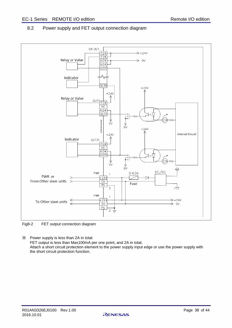
8.2 Power supply and FET output connection diagram .................................................................... 38
9. Dimensional Outline Drawing ......................................................................................... 39
EC-1 Series REMOTE I/O edition Remote I/O edition
R01AN3326EJ0100 Rev.1.00 Page 3 of 44
2016.10.01
10. Appendix ........................................................................................................................ 40
10.1 Appendix A TwinCAT installation ............................................................................................. 40
10.2 Appendix B TwinCATdriver ...................................................................................................... 40
10.1 Appendix C Refresh EC-1 Board E2PROM data from TwinCAT ............................................. 42

EC-1 Series REMOTE I/O edition Remote I/O edition
R01AN3326EJ0100 Rev.1.00 Page 4 of 44
2016.10.01
1. Overviews
1.1 Overviews
This document describes the usage of the digital input and output slave unit corresponding to EtherCAT
communication protocols using EC-1.
1.2 System Configuration
Fig1-1 System configuration
EtherCAT Slave group
Digital input unit
Digital Output unit
Digital Input/Output unit
Analog Output unit
Sensor
Indicater
Switch
Sensor
Switch
Indicater
Voltage input deviceCurrent input device
Voltage Output deviceCurrent Output device
Host system

EC-1 Series REMOTE I/O edition Remote I/O edition
R01AN3326EJ0100 Rev.1.00 Page 5 of 44
2016.10.01
1.3 Block Diagram
EC-1Power Supply
TerminalDC+24V
Digital 3.3V
FB
Digital1.2V
Analog 1.2V
Xtal25MHz
XTAL
RESET-SW
RESET IC(PowerON)
RES#
Serial Flash ROM(512Mbit)
Serial FlashROM I/F
RS485Driver
Connector
EtherPHY0 I/FRJ45Connecter(Built in Trans)
LED x 8bit
PHY
LED x 5bit
JTAG(ICE)20pin Connecter
JTAG I/F
Fuse
EMIFilter
Power ICRAA230153
24V⇒5V
Power ICRAA230233
EtherPHY1 I/FRJ45Connecter(Built in Trans)
PHY
EtherCAT indicator
DigitalIsolator
DIP-SW(4bit)
FTDI(FT232RQ)
UART I/FUSB
Mini-B
GPIO PortDIP-SW(8bit)
LED x 4bit
PowerSwitch
ConnecterPhoto coupler
Remote I/O(NPN Type) Digital output(8ch)
LED x 8bit
ConnecterPhotocoupler
Remote I/O (NPN type) Digital input(8ch)
FB Analog 3.3V
EXTAL
TRST#
EEPROM(16Kbit)
EEPROM I/F
ConnectorCAN
Transceiver
Fig1-2 Block Diagram

EC-1 Series REMOTE I/O edition Remote I/O edition
R01AN3326EJ0100 Rev.1.00 Page 6 of 44
2016.10.01
2. General specification
2.1 Electric
In this chapter, the electrical specifications of this I/O and performance are explained in a table
Item Specification
PWR
Rated Voltage DC24V
Voltage tolerance level DC20.4--26.4V
Internal current consumption ≦100mA
Status LED(POWER) Green
2.2 Operating environment
Item Specification
Environment
Ambient operating temp 0--55℃
Preservation ambient temp -25--70℃
Ambient operating humidity 30--90%RH(no condensation)
Preservation ambient humidity 30--90%RH(no condensation)
Use atmosphere No corrosive gas
Weight - 180g
Dimension - 71(W) x 130.6(H) x 28(D)
2.3 Communication
Item Specification
Communication protocol
Correspondence profile CoE
Communication control LSI
EC-1
EtherCAT PHY TI TLK105
Communication system IEEE802.3u (100Base-TX)
Insulation system Pulse transformer insulation
Status LED RUN(Green), ERR(Red), STATUS(Geen/Red)
L/A IN(Green), L/A OUT(Green)
Interface RJ-45 x 2

EC-1 Series REMOTE I/O edition Remote I/O edition
R01AN3326EJ0100 Rev.1.00 Page 7 of 44
2016.10.01
2.4 Digital Input
Item Specification
Rated input voltage DC24V
Input current ≦4mA / Input
ON voltage ≦15V (terminal--common)
OFF voltage ≦5V (terminal--common)
Input impedance 5.6kΩ
Insulation system Photo coupler Insulation
Input logic Active High
Delay time
OFF→ON ≦0.1ms
ON→OFF ≦0.1ms
Common number 1 common
Status LED Input : Turn on
Interface Connector WAGO 734-236
Input number 8 Input unit
2.5 Digital Output
Item Specification
Rated output voltage DC24V
Output current 0.1A/Output 2A/Unit
Insulation system Photo coupler Insulation
Output system FET
Output protection function Yes
Residual voltage ≦0.5V
Leak current ≦0.1mA
Output logic Active High
Delay time
OFF→ON ≦0.05ms
ON→OFF ≦0.5ms
Common number 1 common
Status LED Output : Turn on
Interface Connector WAGO 734-236
Output number 8 output unit
EC-1 Series REMOTE I/O edition Remote I/O edition
R01AN3326EJ0100 Rev.1.00 Page 8 of 44
2016.10.01
3. Hardware Function
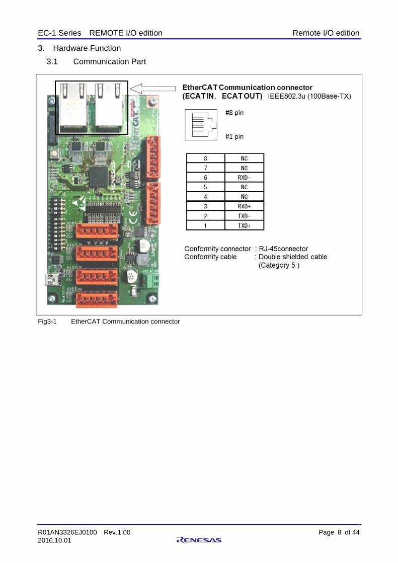
3.1 Communication Part
Fig3-1 EtherCAT Communication connector

EC-1 Series REMOTE I/O edition Remote I/O edition
R01AN3326EJ0100 Rev.1.00 Page 9 of 44
2016.10.01
3.2 Power supply、I/O connector
Fig3-2 Power supply、I/O connector
CAN Communication connector (CN5)
The Pin specifications is shown in the following table 3.1
Table 3-1
Pin# I/O Dir Signal Name
1 - +5V
2 I/O CANH
3 - FG
4 I/O CANL
5 - GND
6 - -
CN5
CN6

EC-1 Series REMOTE I/O edition Remote I/O edition
R01AN3326EJ0100 Rev.1.00 Page 10 of 44
2016.10.01
RS485 Communication connector (CN6)
The Pin specifications is shown in the following table 3.2
Table 3-2
Pin# I/O Dir Signal Name
1 - +5V
2 Output A
3 Output B
4 Input Z
5 Input Y
6 - GND
Digital I/O Interface connector (TB1-TB4)
The Pin specifications is shown in the following table 3.3
TB2 and TB4 connector are only input.
TB1 and TB3 connector are only output.
Table 3-3
Pin# I/O Dir Signal Name
1 - +24V
2 IN or OUT IN*/OUT*
3 IN or OUT IN*/OUT*
4 IN or OUT IN*/OUT*
5 IN or OUT IN*/OUT*
6 - GND

EC-1 Series REMOTE I/O edition Remote I/O edition
R01AN3326EJ0100 Rev.1.00 Page 11 of 44
2016.10.01
3.3 Status LED
Fig3-3 Communication Status LED

EC-1 Series REMOTE I/O edition Remote I/O edition
R01AN3326EJ0100 Rev.1.00 Page 12 of 44
2016.10.01
Fig3-4 Power Supply, I/O Status (user) LEDs
EC-1 Series REMOTE I/O edition Remote I/O edition
R01AN3326EJ0100 Rev.1.00 Page 13 of 44
2016.10.01
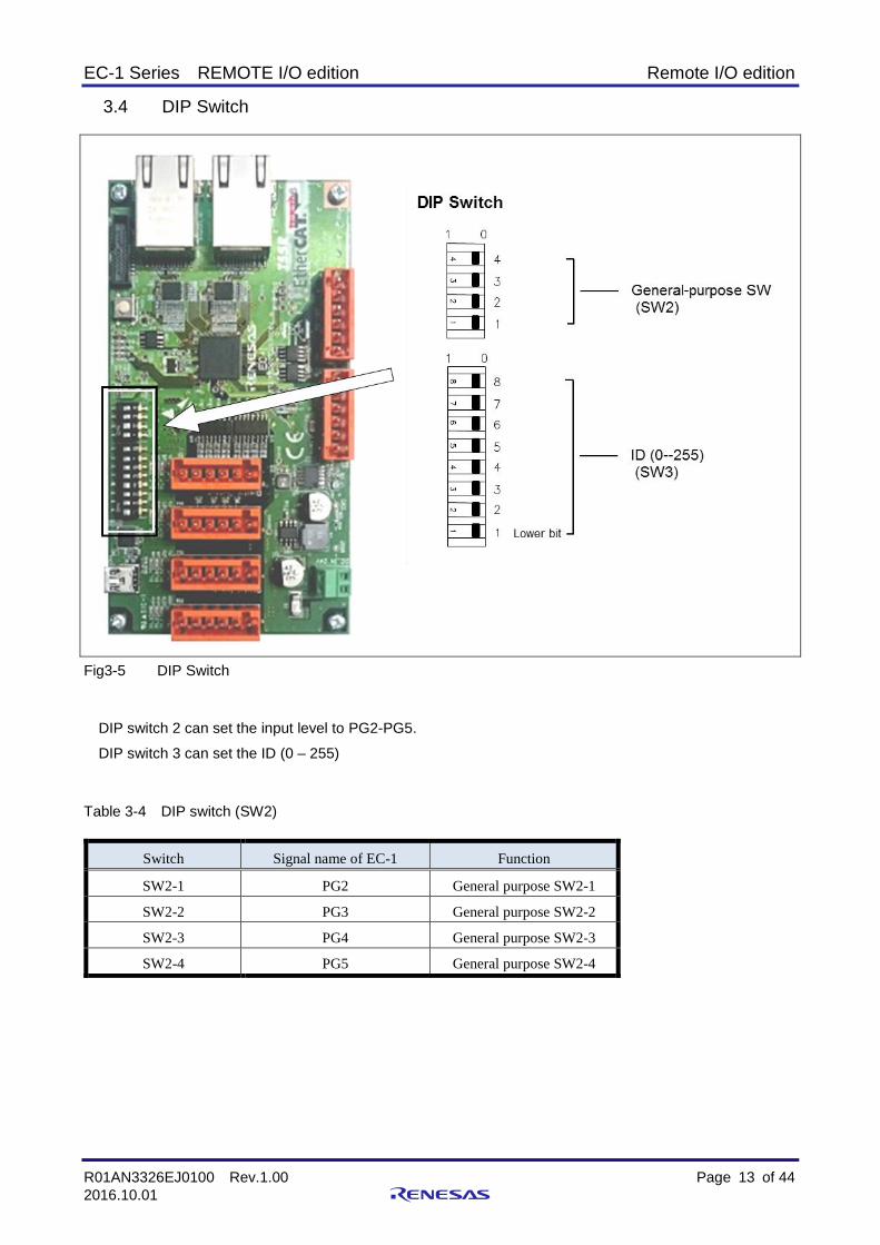
3.4 DIP Switch
Fig3-5 DIP Switch
DIP switch 2 can set the input level to PG2-PG5.
DIP switch 3 can set the ID (0 – 255)
Table 3-4 DIP switch (SW2)
Switch Signal name of EC-1 Function
SW2-1 PG2 General purpose SW2-1
SW2-2 PG3 General purpose SW2-2
SW2-3 PG4 General purpose SW2-3
SW2-4 PG5 General purpose SW2-4

EC-1 Series REMOTE I/O edition Remote I/O edition
R01AN3326EJ0100 Rev.1.00 Page 14 of 44
2016.10.01
3.5 Configuration Switch
Fig3-6 Switch on the board
Reset switch (SW1) This is a push switch to generate reset in EC-1 and this I/O.

EC-1 Series REMOTE I/O edition Remote I/O edition
R01AN3326EJ0100 Rev.1.00 Page 15 of 44
2016.10.01
JTAG connector (CN2)
This is half pitch connector for debug.
Connector : SHF-110-01-L-D-TH
Table 3-5 JTAG CN2
Pin# Signal name Pin# Signal name
1 VRef 2 TMS
3 GND 4 TCK
5 GND 6 TDO
7 --- 8 TDI
9 GND 10 RESET
11 GNDcap 12 GND
13 GNDcap 14 GND
15 GND 16 GND
17 GND 18 GND
19 GND 20 GND
UART connector (CN4)
This is USB-MiniB type connector to use for UART.
Table 3-6 UART CN4
Pin# Signal name
1 VBUS
2 -D
3 +D
4 ID
5 GND

EC-1 Series REMOTE I/O edition Remote I/O edition
R01AN3326EJ0100 Rev.1.00 Page 16 of 44
2016.10.01
TEST Pad Connection Pins The following pins are connected from EC-1 and other chips to probing pads.
PAD : Through hole φ0.8mm
Table 3-7 Pad List
Pin Name Pad Name PAD Connection State
ERROROUT ERR -
TEST# TRSTZ -
RES# RESZ -
P90 P90 -
P91 P91 -
P92 P92 -
P93 P93 -
P94 P94 -
P95 P95 -
P96 P96 -
P97 P97 -
POWER
D24V0 -
D5V0 -
D3V3 -
A3V3 -
D1V2 -
A1V2 -
GND GND1 -
GND2 -
EC-1 Series REMOTE I/O edition Remote I/O edition
R01AN3326EJ0100 Rev.1.00 Page 17 of 44
2016.10.01
4. Object dictionary
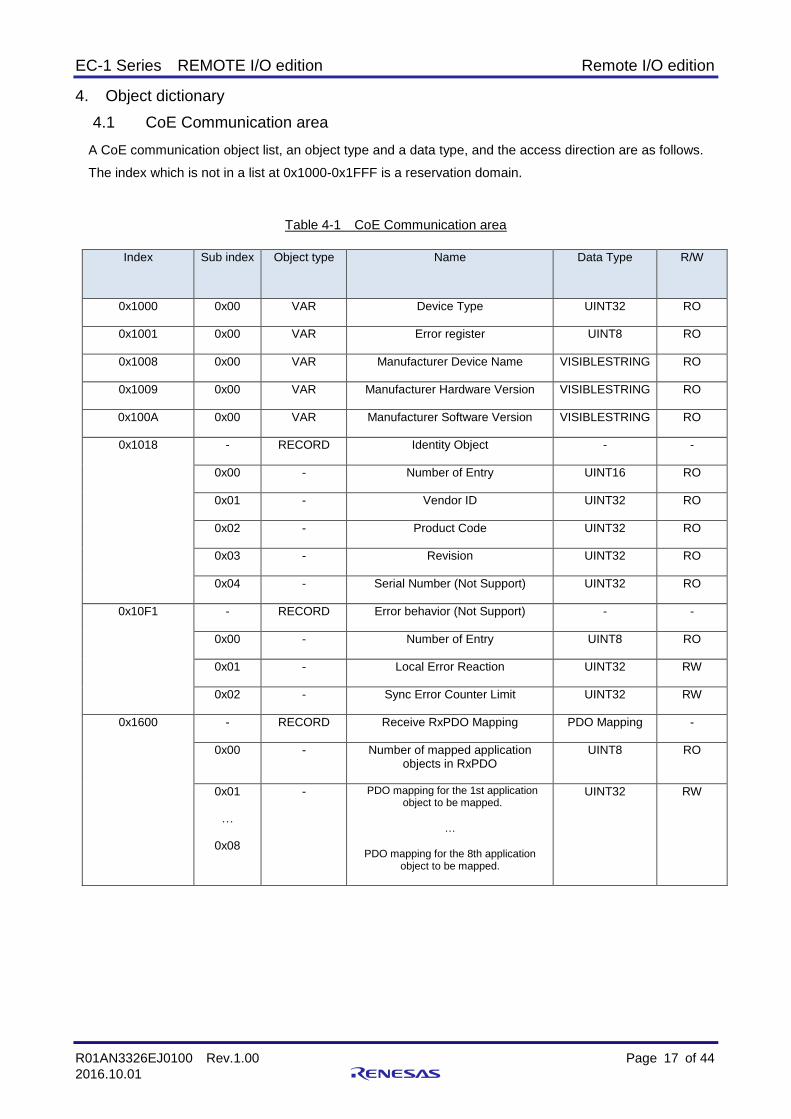
4.1 CoE Communication area
A CoE communication object list, an object type and a data type, and the access direction are as follows.
The index which is not in a list at 0x1000-0x1FFF is a reservation domain.
Table 4-1 CoE Communication area
Index Sub index Object type Name Data Type R/W
0x1000 0x00 VAR Device Type UINT32 RO
0x1001 0x00 VAR Error register UINT8 RO
0x1008 0x00 VAR Manufacturer Device Name VISIBLESTRING RO
0x1009 0x00 VAR Manufacturer Hardware Version VISIBLESTRING RO
0x100A 0x00 VAR Manufacturer Software Version VISIBLESTRING RO
0x1018 - RECORD Identity Object - -
0x00 - Number of Entry UINT16 RO
0x01 - Vendor ID UINT32 RO
0x02 - Product Code UINT32 RO
0x03 - Revision UINT32 RO
0x04 - Serial Number (Not Support) UINT32 RO
0x10F1 - RECORD Error behavior (Not Support) - -
0x00 - Number of Entry UINT8 RO
0x01 - Local Error Reaction UINT32 RW
0x02 - Sync Error Counter Limit UINT32 RW
0x1600 - RECORD Receive RxPDO Mapping PDO Mapping -
0x00 - Number of mapped application objects in RxPDO
UINT8 RO
0x01
…
0x08
- PDO mapping for the 1st application object to be mapped.
…
PDO mapping for the 8th application object to be mapped.
UINT32 RW

EC-1 Series REMOTE I/O edition Remote I/O edition
R01AN3326EJ0100 Rev.1.00 Page 18 of 44
2016.10.01
Index Sub index Object type Name Data Type R/W
0x1A00 - RECORD Transmit TxPDO Mapping PDO Mapping -
0x00 - Number of mapped application objects in TxPDO
UINT8 RW
0x01
…
0x08
- PDO mapping for the 1st application object to be mapped.
…
PDO mapping for the 8th application object to be mapped.
UINT32 RW
0x1C00 - ARRAY SM(Sync Manager) type - -
0x00 - Number of entry UINT8 RO
0x01
…
0x04
- SM0 communication type
…
SM3 communication type
UINT8 RO
0x1C12
…
0x1C13
- RECORD SM2 - SM3 PDO Assignment - -
0x00 - Number of Entry UINT8 RO
0x01 - 1st allocated PDO UINT16 RW(RO)
0x1C32
…
0x1C33
- RECORD SM2 - SM3 Synchronization - -
0x00 - Number of Entry UINT8 RO
0x01 - Sync mode UINT16 RW(RO)
0x02 - Cycle time UINT32 RW(RO)
0x03 - Shift time UINT32 RW(RO)

EC-1 Series REMOTE I/O edition Remote I/O edition
R01AN3326EJ0100 Rev.1.00 Page 19 of 44
2016.10.01
4.2 Device object
Information peculiar to a device is stored.
Index Name Description
0x1000 Device Type Indicates the device profile.
Sub-Index Parameter Data type R/W PDO map
0x00 - UINT32 RO No
Index Name Description
0x1001 Error register The error condition of the EtherCAT slave
Sub-Index Parameter Data type Access PDO map
0x00
Error condition 0x00 No error 0x01 General error 0x10 Communication fault 0x20 Device profile error
UINT8 RO No
Index Name Description
0x1008 Device name Device name of the EtherCAT slave
Sub-Index Parameter Data type R/W PDO map
0x00 Device name
“EC-1 Remote I/O VISIBLE STRING RO No
Index Name Description
0x1009 Hardware version Hardware version of the EtherCAT slave
Sub-Index Parameter Data type R/W PDO map
0x00 Hardware version
“1.0” VISIBLE STRING RO No
Index Name Description
0x100A Software version Firmware version of the EtherCAT slave
Sub-Index Parameter Data type R/W PDO map
0x00 Software version “1.01”
VISIBLE STRING RO No
Index Name Description
0x1018 Identity Information for identifying the slave
Sub-Index Parameter Data type R/W PDO map
0x00 Number of entry
“4” UINT16 RO No
0x01 Vendor ID
“0x00000766” UINT32 RO No
0x02 Product code
“0x00000501” UINT32 RO No
0x03 Revision
“0x00000001” UINT32 RO No
0x04 Serial number (Not Support)
“0x00000000” UINT32 RO No
31 19 18 16 15 0
0 0 0 0 0 0 0 0 0 0 0 0 0 0
Number of device profile (value 0x191)
Input unit is 1, other is 0.
Output unit is 1, other is 0.

EC-1 Series REMOTE I/O edition Remote I/O edition
R01AN3326EJ0100 Rev.1.00 Page 20 of 44
2016.10.01
Index Name Description
0x10F1 Error behavior (Not Support) Error configuration information
Sub-Index Parameter Data type Sub-Index Parameter
0x00 Number of entry UINT8 RO No
0x01 Local Error Reaction UINT32 RW No
0x02 Sync Error Counter Limit UINT16 RW No
4.3 PDO mapping
The communication transmission data between master and slaves is assigned to the EtherCAT I/O unit in advance. The user can access PDO, without changing.
The details of the PDO mapping entry of 0x1600 and 0x1A00 are shown below.
● 0x1600:Receive RxPDO Mapping
Index Name Description
0x1600
RxPDO1 Entry of a RxPDO1 mapping object dictionary
Sub-Index Parameter Data type R/W PDO map
0x00 Number of Entry UINT8 RW No
0x01 Digital Output Bit0 UINT32 RW 0x7000:0x01
0x02 Digital Output Bit1 UINT32 RW 0x7000:0x02
0x03 Digital Output Bit2 UINT32 RW 0x7000:0x03
0x04 Digital Output Bit3 UINT32 RW 0x7000:0x04
0x05 Digital Output Bit4 UINT32 RW 0x7000:0x05
0x06 Digital Output Bit5 UINT32 RW 0x7000:0x06
0x07 Digital Output Bit6 UINT32 RW 0x7000:0x07
0x08 Digital Output Bit7 UINT32 RW 0x7000:0x08
● 0x1A00:Transmit TxPDO Mapping
Index Name Description
0x1A00
TxPDO1 Entry of a TxPDO1 mapping object dictionary
Sub-Index Parameter Data type R/W PDO map
0x00 Number of Entry UINT8 RW No
0x01 Digital Input Bit0 UINT32 RW 0x6000:0x01
0x02 Digital Input Bit1 UINT32 RW 0x6000:0x02
0x03 Digital Input Bit2 UINT32 RW 0x6000:0x03
0x04 Digital Input Bit3 UINT32 RW 0x6000:0x04
0x05 Digital Input Bit4 UINT32 RW 0x6000:0x05
0x06 Digital Input Bit5 UINT32 RW 0x6000:0x06
0x07 Digital Input Bit6 UINT32 RW 0x6000:0x07
0x08 Digital Input Bit7 UINT32 RW 0x6000:0x08
EC-1 Series REMOTE I/O edition Remote I/O edition
R01AN3326EJ0100 Rev.1.00 Page 21 of 44
2016.10.01
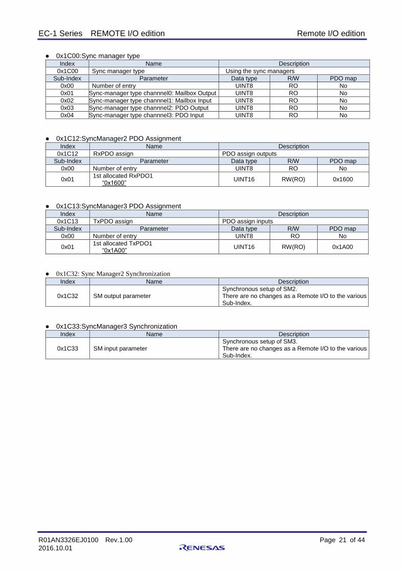
● 0x1C00:Sync manager type
Index Name Description
0x1C00 Sync manager type Using the sync managers
Sub-Index Parameter Data type R/W PDO map
0x00 Number of entry UINT8 RO No
0x01 Sync-manager type channnel0: Mailbox Output UINT8 RO No
0x02 Sync-manager type channnel1: Mailbox Input UINT8 RO No
0x03 Sync-manager type channnel2: PDO Output UINT8 RO No
0x04 Sync-manager type channnel3: PDO Input UINT8 RO No
● 0x1C12:SyncManager2 PDO Assignment
Index Name Description
0x1C12 RxPDO assign PDO assign outputs
Sub-Index Parameter Data type R/W PDO map
0x00 Number of entry UINT8 RO No
0x01 1st allocated RxPDO1
“0x1600” UINT16 RW(RO) 0x1600
● 0x1C13:SyncManager3 PDO Assignment
Index Name Description
0x1C13 TxPDO assign PDO assign inputs
Sub-Index Parameter Data type R/W PDO map
0x00 Number of entry UINT8 RO No
0x01 1st allocated TxPDO1 “0x1A00”
UINT16 RW(RO) 0x1A00
● 0x1C32: Sync Manager2 Synchronization
Index Name Description
0x1C32 SM output parameter Synchronous setup of SM2. There are no changes as a Remote I/O to the various Sub-Index.
● 0x1C33:SyncManager3 Synchronization Index Name Description
0x1C33 SM input parameter Synchronous setup of SM3. There are no changes as a Remote I/O to the various Sub-Index.
EC-1 Series REMOTE I/O edition Remote I/O edition
R01AN3326EJ0100 Rev.1.00 Page 22 of 44
2016.10.01
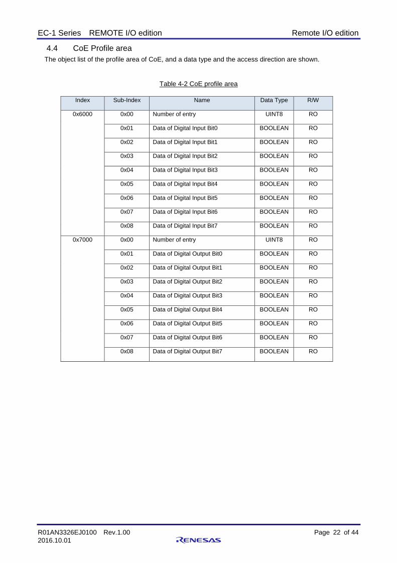
4.4 CoE Profile area
The object list of the profile area of CoE, and a data type and the access direction are shown.
Table 4-2 CoE profile area
Index Sub-Index Name Data Type R/W
0x6000 0x00 Number of entry UINT8 RO
0x01 Data of Digital Input Bit0 BOOLEAN RO
0x02 Data of Digital Input Bit1 BOOLEAN RO
0x03 Data of Digital Input Bit2 BOOLEAN RO
0x04 Data of Digital Input Bit3 BOOLEAN RO
0x05 Data of Digital Input Bit4 BOOLEAN RO
0x06 Data of Digital Input Bit5 BOOLEAN RO
0x07 Data of Digital Input Bit6 BOOLEAN RO
0x08 Data of Digital Input Bit7 BOOLEAN RO
0x7000 0x00 Number of entry UINT8 RO
0x01 Data of Digital Output Bit0 BOOLEAN RO
0x02 Data of Digital Output Bit1 BOOLEAN RO
0x03 Data of Digital Output Bit2 BOOLEAN RO
0x04 Data of Digital Output Bit3 BOOLEAN RO
0x05 Data of Digital Output Bit4 BOOLEAN RO
0x06 Data of Digital Output Bit5 BOOLEAN RO
0x07 Data of Digital Output Bit6 BOOLEAN RO
0x08 Data of Digital Output Bit7 BOOLEAN RO

EC-1 Series REMOTE I/O edition Remote I/O edition
R01AN3326EJ0100 Rev.1.00 Page 23 of 44
2016.10.01
4.5 CoE Profile area parameter
● 0x6000:Digital Input Bit0-7
Index Digital Input1 0x6000
Sub-Index Parameter Data type R/W Default
0x00 Number of entry UINT8 RO 0x08
0x01 Digital Input Bit0(DI0) The data inputted into DI0 is displayed.
BOOLEAN RO 0
0x02 Digital Input Bit1(DI1) The data inputted into DI1 is displayed.
BOOLEAN RO 0
0x03 Digital Input Bit2(DI2) The data inputted into DI2 is displayed.
BOOLEAN RO 0
0x04 Digital Input Bit3(DI3) The data inputted into DI3 is displayed.
BOOLEAN RO 0
0x05 Digital Input Bit4(DI4) The data inputted into DI4 is displayed.
BOOLEAN RO 0
0x06 Digital Input Bit5(DI5) The data inputted into DI5 is displayed.
BOOLEAN RO 0
0x07 Digital Input Bit6(DI6) The data inputted into DI6 is displayed.
BOOLEAN RO 0
0x08 Digital Input Bit7(DI7) The data inputted into DI7 is displayed.
BOOLEAN RO 0
● 0x7000:Digital Output Bit0-7
Index Digital Output1 0x7000
Sub-Index Parameter Data type R/W Default
0x00 Number of entry UINT8 RO 0x08
0x01 Digital Output Bit0(DO0) The data outputted to DO0 is displayed.
BOOLEAN RW 0
0x02 Digital Output Bit1(DO1) The data outputted to DO1 is displayed.
BOOLEAN RW 0
0x03 Digital Output Bit2(DO2) The data outputted to DO2 is displayed.
BOOLEAN RW 0
0x04 Digital Output Bit3(DO3) The data outputted to DO3 is displayed.
BOOLEAN RW 0
0x05 Digital Output Bit4(DO4) The data outputted to DO4 is displayed.
BOOLEAN RW 0
0x06 Digital Output Bit5(DO5) The data outputted to DO5 is displayed.
BOOLEAN RW 0
0x07 Digital Output Bit6(DO6) The data outputted to DO6 is displayed.
BOOLEAN RW 0
0x08 Digital Output Bit7(DO7) The data outputted to DO7 is displayed.
BOOLEAN RW 0
EC-1 Series REMOTE I/O edition Remote I/O edition
R01AN3326EJ0100 Rev.1.00 Page 24 of 44
2016.10.01
5. Sample software for EtherCAT protocol
This chapter describes a method of using EtherCAT Slave Stack Code (SSC), to build a remote I/O
software.
Please prepare if you want to use the SSC, it is necessary to obtain a license.
5.1 Sample software construction environment
The sample program construction environment of this manual assumes the following.
IDE :IAR Systems
Embedded Workbench for ARM Version 7.7x.x and later
Emulators:IAR Systems
I-jet or or equivalent,
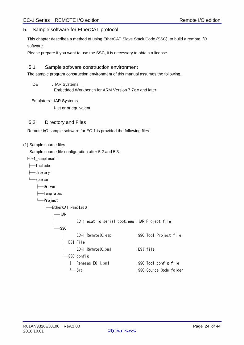
5.2 Directory and Files
Remote I/O sample software for EC-1 is provided the following files.
(1) Sample source files
Sample source file configuration after 5.2 and 5.3.
EC-1_samplesoft
├─Include
├─Library
└─Source
├─Driver
├─Templates
└─Project
└─EtherCAT_RemoteIO
├─IAR
│ EC_1_ecat_io_serial_boot.eww:IAR Project file
└─SSC
│ EC-1_RemoteIO.esp :SSC Tool Project file
├─ESI_File
│ EC-1_RemoteIO.xml :ESI file
└─SSC_config
│ Renesas_EC-1.xml :SSC Tool config file
└─Src :SSC Source Code folder

EC-1 Series REMOTE I/O edition Remote I/O edition
R01AN3326EJ0100 Rev.1.00 Page 25 of 44
2016.10.01
(2) EtherCAT Slave Stack Code(SSC)
The source code that is automatically generated by the EtherCAT Slave Stack Code Tool (SSC Tool) is
used in this sample software.
SSC Tool project file is put on the following folder.
Refer to the next chapter for automatic generation by SSC Tool.
EC-1_samplesoft/Source/Project/EtherCAT_RemoteIO/SSC/EC-1_RemoteIO.esp
(3) ESI File
Please use the following file for ESI file.
EC-1_samplesoft/Source/Project/EtherCAT_RemoteIO/SSC/ESI_File/ EC-1_RemoteIO.xml

EC-1 Series REMOTE I/O edition Remote I/O edition
R01AN3326EJ0100 Rev.1.00 Page 26 of 44
2016.10.01
5.3 How to create EtherCAT Slave Stack Code(SSC)
The following folder contains the project file “EC-1_RemoteIO.esp”.
EC-1_samplesoft/Source/Project/EtherCAT_RemoteIO/SSC
Please follow the procedure below to create source-code with project file “EC-1_RemoteIO.esp”.
(1) After executing the project file, a following dialog is displayed.

EC-1 Series REMOTE I/O edition Remote I/O edition
R01AN3326EJ0100 Rev.1.00 Page 27 of 44
2016.10.01
(2) Select “Create new Slave Files”.
Click the [Project] – [Create new Slave Files] from the menu.

EC-1 Series REMOTE I/O edition Remote I/O edition
R01AN3326EJ0100 Rev.1.00 Page 28 of 44
2016.10.01
(3) Create the source files.
At open window “Create new Slave Files”, creation of source files are started by click the [start] button.
Source Folder will be automatically generated in the path of the following.
EC-1_samplesoft/Source/Project/EtherCAT_RemoteIO/SSC/Src

EC-1 Series REMOTE I/O edition Remote I/O edition
R01AN3326EJ0100 Rev.1.00 Page 29 of 44
2016.10.01
(4) Create the source files.
Creation of the file is complete, and the following dialog box is displayed

EC-1 Series REMOTE I/O edition Remote I/O edition
R01AN3326EJ0100 Rev.1.00 Page 30 of 44
2016.10.01
6. Prepare for the EtherCAT Communication
6.1 Copy ESI (EtherCAT Slave Information) file
Copy the “EC-1_RemoteIO.xml” file under the following folders which installed TwinCAT
ESI file is located in the following folder
EC-1_samplesoft/Source/Project/EtherCAT_RemoteIO/SSC/ESI_File
Obtaining of TwinCAT, please refer to Appendix A.
■in case of TwinCAT2
TwinCAT/Io/EtherCAT
■in case of TwinCAT3
TwinCAT/3.1/Config/Io/EtherCAT
6.2 Setting the PC network environment
Set the network environment of the PC to use for EtherCAT driver.
Display the connect network adapter property, and choose only the TwinCAT driver "TwinCAT Ethernet
Protocol".
If the TwinCAT driver does not appear, or the installation of TwinCAT driver is unfinished, please refer to
Appendix B.

EC-1 Series REMOTE I/O edition Remote I/O edition
R01AN3326EJ0100 Rev.1.00 Page 31 of 44
2016.10.01
6.3 Board Connection
Please establish the following connections between the EC-1 board and the PC
(1) Connect Ethernet Port 0 to your PC (with TwinCAT installed) with an Ethernet cable (recommend Category 5 ).
(2) Please connect the 20 pin half pitch connector from the debugger. (3) Please connect the 24V-2A DC adaptor.
6.4 Start EWARM
Double click the file “EC-1_serial_boot .eww” in the SampleSoft installation found in the EC-1_samplesoft/Source/Project/EtherCAT_RemoteIO/IAR
folder. The IAR Embedded Workbench IDE will start automatically.
(1) Execute the compile (2) Run download and debug. (3) Run the program.

EC-1 Series REMOTE I/O edition Remote I/O edition
R01AN3326EJ0100 Rev.1.00 Page 32 of 44
2016.10.01
7. Connection with TwinCAT
7.1 Start up TwinCAT
■In the case of TwinCAT2
Please activate the “TwinCAT XAE” program using one of the following methods:
(1) Task tray ⇒ [TwinCAT System Manager]
(2) Start menu ⇒ [TwinCAT System] ⇒ [TwinCAT System Manager]
■In the case of TwinCAT3
Please activate the “TwinCAT XAE” program using one of the following methods:
(1) Task tray ⇒ [TwinCAT Config Mode] ⇒ [TwinCAT XAE (VS2010)]
(2) Start menu ⇒ [Beckhoff] ⇒[TwinCAT3] ⇒ [TwinCAT XAE (VS2010)]
After activating the program, please select [File] ⇒ [New] ⇒ [Project] and make a new project as a
TwinCAT XAE Project type.
7.2 Scan I/O devices
The following operation is similar for both TwinCAT2 and TwinCAT3
The image below is an example of the TwinCAT3 operation.
(1) Rite click on [Devices] and select [Scan].
(2) Select [OK] and Scan is running.
(3) Select [EtherCAT] Device and [OK].

EC-1 Series REMOTE I/O edition Remote I/O edition
R01AN3326EJ0100 Rev.1.00 Page 33 of 44
2016.10.01
[NOTE] If the EtherCAT Device does not display, confirm the following factors EC-1 Board and PC(TwinCAT) disconnect
Connect EC-1 Board and PC with Ethernet cable Network adapter setting is not selected to EtherCAT
Refer to 6.2 EtherCAT driver is not installed
Refer to Appendix B
(4) Select [Yes] and Scan Box.
EC-1 Series REMOTE I/O edition Remote I/O edition
R01AN3326EJ0100 Rev.1.00 Page 34 of 44
2016.10.01
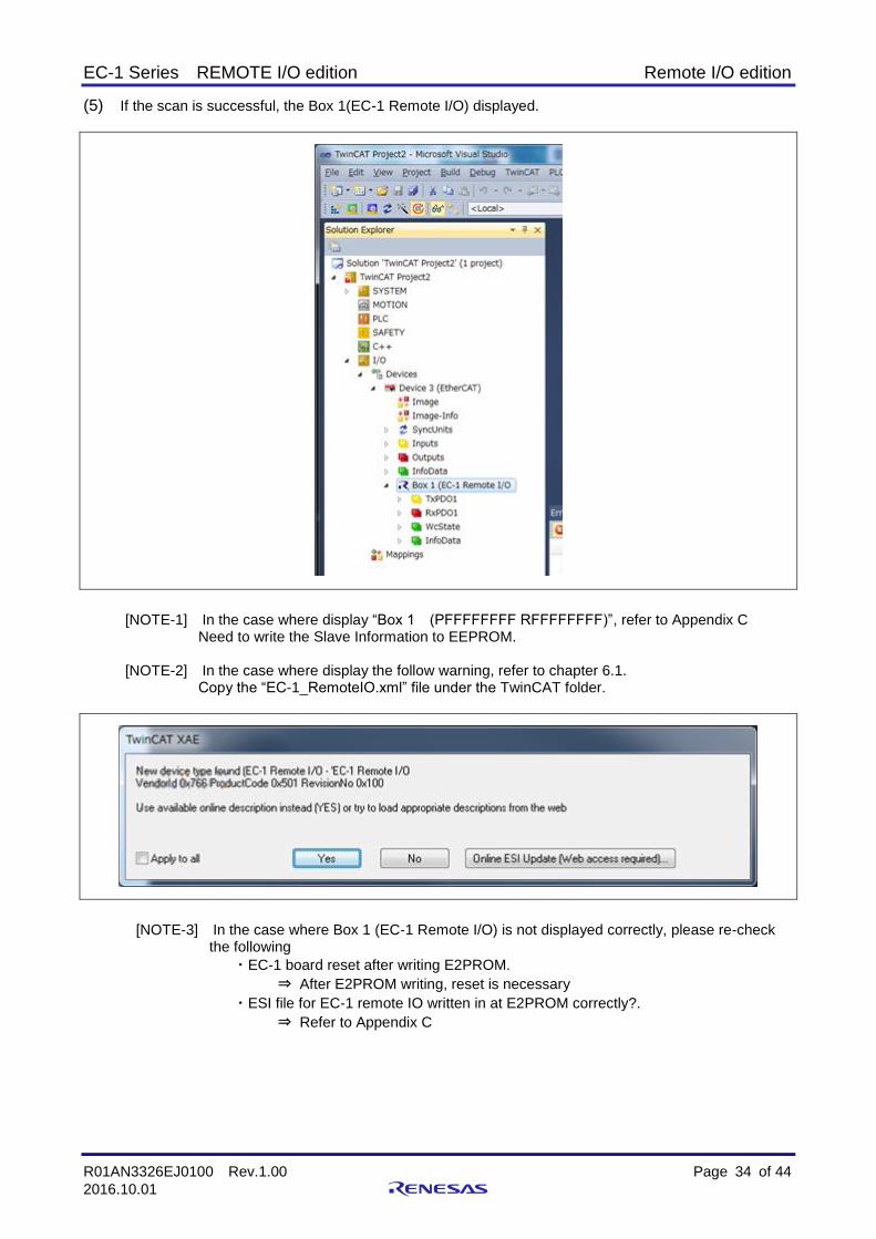
(5) If the scan is successful, the Box 1(EC-1 Remote I/O) displayed.
[NOTE-1] In the case where display “Box 1 (PFFFFFFFF RFFFFFFFF)”, refer to Appendix C Need to write the Slave Information to EEPROM.
[NOTE-2] In the case where display the follow warning, refer to chapter 6.1.
Copy the “EC-1_RemoteIO.xml” file under the TwinCAT folder.
[NOTE-3] In the case where Box 1 (EC-1 Remote I/O) is not displayed correctly, please re-check the following
・EC-1 board reset after writing E2PROM.
⇒ After E2PROM writing, reset is necessary
・ESI file for EC-1 remote IO written in at E2PROM correctly?.
⇒ Refer to Appendix C

EC-1 Series REMOTE I/O edition Remote I/O edition
R01AN3326EJ0100 Rev.1.00 Page 35 of 44
2016.10.01
7.3 Data Read/Write
Read / Write data with TwinCAT and EC-1 Board.
■ Read (EC-1 board to TwinCAT)
(1) Open the TxPDO1 of Box1 EC-1 RemoteI/O
(2) Input any bit set to "1" from RemoteIO.
The selected bit is reflected in the onlines.

EC-1 Series REMOTE I/O edition Remote I/O edition
R01AN3326EJ0100 Rev.1.00 Page 36 of 44
2016.10.01
■ Write (TwinCAT to EC-1 board)
(1) Open the RxPDO1 of Box1 EC-1 RemoteI/O
(2) Select any bit and click [Online Write]
(3) Set the write values in “Set Value Dialog”, the EC-1 Board selected LED will light up.

EC-1 Series REMOTE I/O edition Remote I/O edition
R01AN3326EJ0100 Rev.1.00 Page 37 of 44
2016.10.01
8. Connection with external equipment
8.1 Power supply and Photo coupler input connection diagram
It is the connection method of the power supply and photocoupler input part.
Fig8-1 Photo coupler input connection diagram
※ Power supply is less than 2A in total.
Attach a short circuit protection element to the power supply input edge or use the power supply with the short circuit protection function.
EC-1 Series REMOTE I/O edition Remote I/O edition
R01AN3326EJ0100 Rev.1.00 Page 38 of 44
2016.10.01
8.2 Power supply and FET output connection diagram
Fig8-2 FET output connection diagram
※ Power supply is less than 2A in total.
FET output is less than Max100mA per one point, and 2A in total. Attach a short circuit protection element to the power supply input edge or use the power supply with the short circuit protection function.

EC-1 Series REMOTE I/O edition Remote I/O edition
R01AN3326EJ0100 Rev.1.00 Page 39 of 44
2016.10.01
9. Dimensional Outline Drawing
Fig9-1 Outline Drawing

EC-1 Series REMOTE I/O edition Remote I/O edition
R01AN3326EJ0100 Rev.1.00 Page 40 of 44
2016.10.01
10. Appendix
10.1 Appendix A TwinCAT installation
TwinCAT is available from Beckhoff Automation Corporation.
http://www.beckhoff.com/
10.2 Appendix B TwinCATdriver
To use the TwinCAT, must install the TwinCAT driver.
The installation procedure is showed as follows.
(1) TwinCAT starting
■In the case of TwinCAT2
By a method of either following, please start up a program.
・ Task tray ⇒[TwinCAT System Manager]
・ Start menu ⇒[TwinCAT System] ⇒ [TwinCAT System Manager]
■In the case of TwinCAT3
By a method of either following, please start up a program.
・ Task tray ⇒[TwinCAT Config Mode] ⇒ [TwinCAT XAE (VS2010)]
・ Start menu ⇒ [Beckhoff] ⇒ [TwinCAT3] ⇒ [TwinCAT XAE (VS2010)]
(2) Display the Ethernet adapter
■In the case of TwinCAT2
[Option] ⇒ [Show real Time Ethernet Compatible Devices…]
■In the case of TwinCAT3
[TwinCAT] ⇒ [Show real Time Ethernet Compatible Devices…]
EC-1 Series REMOTE I/O edition Remote I/O edition
R01AN3326EJ0100 Rev.1.00 Page 41 of 44
2016.10.01
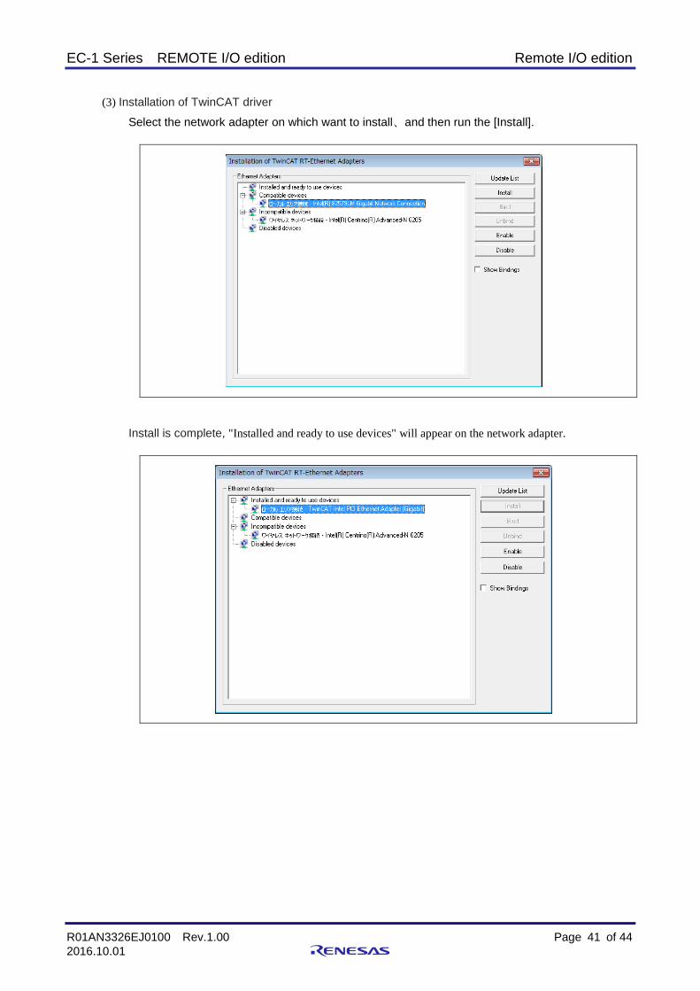
(3) Installation of TwinCAT driver
Select the network adapter on which want to install、and then run the [Install].
Install is complete, "Installed and ready to use devices" will appear on the network adapter.
EC-1 Series REMOTE I/O edition Remote I/O edition
R01AN3326EJ0100 Rev.1.00 Page 42 of 44
2016.10.01
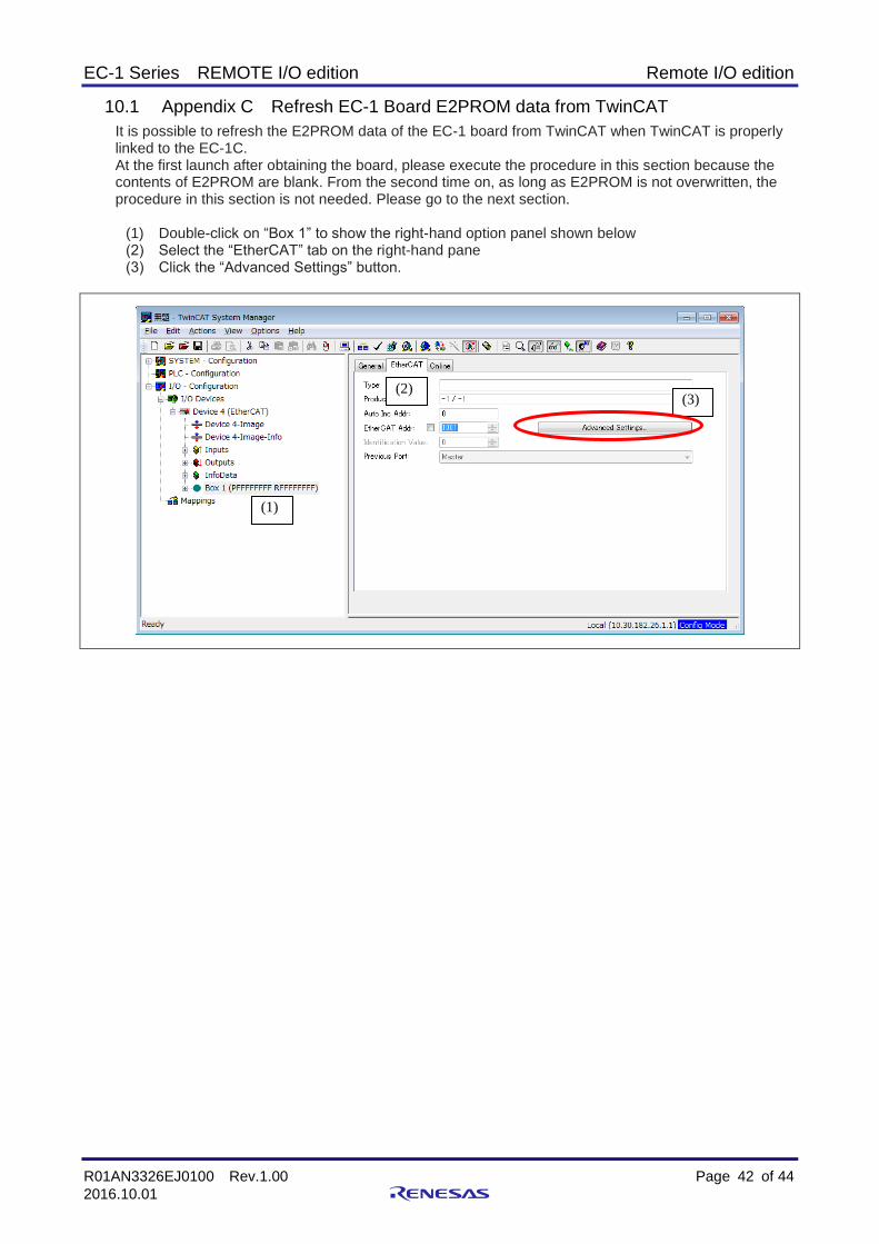
10.1 Appendix C Refresh EC-1 Board E2PROM data from TwinCAT
It is possible to refresh the E2PROM data of the EC-1 board from TwinCAT when TwinCAT is properly linked to the EC-1C. At the first launch after obtaining the board, please execute the procedure in this section because the contents of E2PROM are blank. From the second time on, as long as E2PROM is not overwritten, the procedure in this section is not needed. Please go to the next section.
(1) Double-click on “Box 1” to show the right-hand option panel shown below (2) Select the “EtherCAT” tab on the right-hand pane (3) Click the “Advanced Settings” button.
(1)
(2) (3)

EC-1 Series REMOTE I/O edition Remote I/O edition
R01AN3326EJ0100 Rev.1.00 Page 43 of 44
2016.10.01
(4) Click on “E2PROM” --“Hex Editor” to show the option panel. (5) Select the“Download from List”tab
(6) Select the EC-1 RemoteI/O ESI file “EC-1 Remote I/O”, click [OK] and EEPROM write.
(4)
(5)

EC-1 Series REMOTE I/O edition Remote I/O edition
R01AN3326EJ0100 Rev.1.00 Page 44 of 44
2016.10.01
(7) The transfer is successful if the data display in [Hex Editor].

REVISION HISTORY
Rev. Date Description
Page Summary
1.00 2016.10.01 - First edition issued

Instructions for the use of product
In this section, the precautions are described for over whole of CMOS device.
Please refer to this manual about individual precaution.
When there is a mention unlike the text of this manual, a mention of the text takes first priority
1. Handling of Unused Pins
Handle unused pins in accord with the directions given under Handling of Unused Pins in the manual. - The input pins of CMOS products are generally in the high-impedance state. In operation with an unused pin in
the open-circuit state, extra electromagnetic noise is induced in the vicinity of LSI, associated shoot-through current flows internally, and malfunctions occur due to the false recognition of the pin state as an input signal become possible. Unused pins should be handled as described under Handling of Unused Pins in the manual.
2. Processing at Power-on
The state of the product is undefined at the moment when power is supplied. - The states of internal circuits in the LSI are indeterminate and the states of register settings and pins are
undefined at the moment when power is supplied. In a finished product where the reset signal is applied to the external reset pin, the states of pins are not guaranteed from the moment when power is supplied until the reset process is completed. In a similar way, the states of pins in a product that is reset by an on-chip power-on reset function are not guaranteed from the moment when power is supplied until the power reaches the level at which resetting has been specified.
3. Prohibition of Access to Reserved Addresses
Access to reserved addresses is prohibited. - The reserved addresses are provided for the possible future expansion of functions. Do not access these
addresses; the correct operation of LSI is not guaranteed if they are accessed.
4. Clock Signals
After applying a reset, only release the reset line after the operating clock signal has become stable. When switching the clock signal during program execution, wait until the target clock signal has stabilized. - When the clock signal is generated with an external resonator (or from an external oscillator) during a reset,
ensure that the reset line is only released after full stabilization of the clock signal. Moreover, when switching to a clock signal produced with an external resonator (or by an external oscillator) while program execution is in progress, wait until the target clock signal is stable.
・ ARM, AMBA, ARM Cortex, Thumb and ARM Cortex-R4 are a trademark or a registered trademark of ARM Limited in EU and other countries.
・ EtherCAT® is registered trademark and patented technology, licensed by Beckhoff Automation GmbH, Germany.
・ TwinCAT® is registered trademark of and licensed by Beckhoff Automation GmbH
・ IEEE is a registered trademark of the Institute of Electrical and Electronics Engineers, Inc.
・ Additionally all product names and service names in this document are a trademark or a registered trademark which belongs to the respective owners.

Renesas Electronics Corporation SALES OFFICES http://www.renesas.com
Renesas Electronics America Inc.
2880 Scott Boulevard Santa Clara, CA 95050-2554, U.S.A. Tel: +1-408-588-6000, Fax: +1-408-588-6130 Renesas Electronics Canada Limited 1101 Nicholson Road, Newmarket, Ontario L3Y 9C3, Canada Tel: +1-905-898-5441, Fax: +1-905-898-3220 Renesas Electronics Europe Limited
Dukes Meadow, Millboard Road, Bourne End, Buckinghamshire, SL8 5FH, U.K Tel: +44-1628-651-700, Fax: +44-1628-651-804 Renesas Electronics Europe GmbH Arcadiastrasse 10, 40472 Düsseldorf, Germany Tel: +49-211-65030, Fax: +49-211-6503-1327 Renesas Electronics (China) Co., Ltd.
7th Floor, Quantum Plaza, No.27 ZhiChunLu Haidian District, Beijing 100083, P.R.China Tel: +86-10-8235-1155, Fax: +86-10-8235-7679 Renesas Electronics (Shanghai) Co., Ltd. Unit 204, 205, AZIA Center, No.1233 Lujiazui Ring Rd., Pudong District, Shanghai 200120, China Tel: +86-21-5877-1818, Fax: +86-21-6887-7858 / -7898 Renesas Electronics Hong Kong Limited
Unit 1601-1613, 16/F., Tower 2, Grand Century Place, 193 Prince Edward Road West, Mongkok, Kowloon, Hong Kong Tel: +852-2886-9318, Fax: +852 2886-9022/9044 Renesas Electronics Taiwan Co., Ltd. 13F, No. 363, Fu Shing North Road, Taipei, Taiwan Tel: +886-2-8175-9600, Fax: +886 2-8175-9670 Renesas Electronics Singapore Pte. Ltd.
80 Bendemeer Road, Unit #06-02 Hyflux Innovation Centre Singapore 339949 Tel: +65-6213-0200, Fax: +65-6213-0300 Renesas Electronics Malaysia Sdn.Bhd. Unit 906, Block B, Menara Amcorp, Amcorp Trade Centre, No. 18, Jln Persiaran Barat, 46050 Petaling Jaya, Selangor Darul Ehsan, Malaysia Tel: +60-3-7955-9390, Fax: +60-3-7955-9510 Renesas Electronics Korea Co., Ltd.
11F., Samik Lavied' or Bldg., 720-2 Yeoksam-Dong, Kangnam-Ku, Seoul 135-080, Korea Tel: +82-2-558-3737, Fax: +82-2-558-5141
© 2015-2016 Renesas Electronics Corporation. All rights reserved
Notice 1. Descriptions of circuits, software and other related information in this document are provided only to illustrate the operation of semiconductor products and application examples. You are
fully responsible for the incorporation of these circuits, software, and information in the design of your equipment. Renesas Electronics assumes no responsibility for any losses incurred by you or third parties arising from the use of these circuits, software, or information.
2. Renesas Electronics has used reasonable care in preparing the information included in this document, but Renesas Electronics does not warrant that such information is error free. Renesas Electronics assumes no liability whatsoever for any damages incurred by you resulting from errors in or omissions from the information included herein.
3. Renesas Electronics does not assume any liability for infringement of patents, copyrights, or other intellectual property rights of third parties by or arising from the use of Renesas Electronics products or technical information described in this document. No license, express, implied or otherwise, is granted hereby under any patents, copyrights or other intellectual property rights of Renesas Electronics or others.
4. You should not alter, modify, copy, or otherwise misappropriate any Renesas Electronics product, whether in whole or in part. Renesas Electronics assumes no responsibility for any losses incurred by you or third parties arising from such alteration, modification, copy or otherwise misappropriation of Renesas Electronics product.
5. Renesas Electronics products are classified according to the following two quality grades: "Standard" and "High Quality". The recommended applications for each Renesas Electronics product depends on the product's quality grade, as indicated below.
"Standard": Computers; office equipment; communications equipment; test and measurement equipment; audio and visual equipment; home electronic appliances; machine tools;
personal electronic equipment; and industrial robots etc. "High Quality": Transportation equipment (automobiles, trains, ships, etc.); traffic control systems; anti-disaster systems; anti-crime systems; and safety equipment etc.
Renesas Electronics products are neither intended nor authorized for use in products or systems that may pose a direct threat to human life or bodily injury (artificial life support devices or systems, surgical implantations etc.), or may cause serious property damages (nuclear reactor control systems, military
equipment etc.). You must check the quality grade of each Renesas Electronics product before using it in a particular application. You may not use any Renesas Electronics product for any application for which it is not intended. Renesas Electronics shall not be in any way liable for any damages or losses incurred by you or third parties arising from the use of any Renesas Electronics product for which the product is not intended by Renesas Electronics.
6. You should use the Renesas Electronics products described in this document within the range specified by Renesas Electronics, especially with respect to the maximum rating, operating supply voltage range, movement power voltage range, heat radiation characteristics, installation and other product characteristics. Renesas Electronics shall have no liability for malfunctions or damages arising out of the use of Renesas Electronics products beyond such specified ranges.
7. Although Renesas Electronics endeavors to improve the quality and reliability of its products, semiconductor products have specific characteristics such as the occurrence of failure at a certain rate and malfunctions under certain use conditions. Further, Renesas Electronics products are not subject to radiation resistance design. Please be sure to implement safety measures to guard them against the possibility of physical injury, and injury or damage caused by fire in the event of the failure of a Renesas Electronics product, such as safety design for hardware and software including but not limited to redundancy, fire control and malfunction prevention, appropriate treatment for aging degradation or any other appropriate measures. Because the evaluation of microcomputer software alone is very difficult, please evaluate the safety of the final products or systems manufactured by you.
8. Please contact a Renesas Electronics sales office for details as to environmental matters such as the environmental compatibility of each Renesas Electronics product. Please use Renesas Electronics products in compliance with all applicable laws and regulations that regulate the inclusion or use of controlled substances, including without limitation, the EU RoHS Directive. Renesas Electronics assumes no liability for damages or losses occurring as a result of your noncompliance with applicable laws and regulations.
9. Renesas Electronics products and technology may not be used for or incorporated into any products or systems whose manufacture, use, or sale is prohibited under any applicable domestic or foreign laws or regulations. You should not use Renesas Electronics products or technology described in this document for any purpose relating to military applications or use by the military, including but not limited to the development of weapons of mass destruction. When exporting the Renesas Electronics products or technology described in this document, you should comply with the applicable export control laws and regulations and follow the procedures required by such laws and regulations.
10. It is the responsibility of the buyer or distributor of Renesas Electronics products, who distributes, disposes of, or otherwise places the product with a third party, to notify such third party in advance of the contents and conditions set forth in this document, Renesas Electronics assumes no responsibility for any losses incurred by you or third parties as a result of unauthorized use of Renesas Electronics products.
11. This document may not be reproduced or duplicated in any form, in whole or in part, without prior written consent of Renesas Electronics. 12. Please contact a Renesas Electronics sales office if you have any questions regarding the information contained in this document or Renesas Electronics products, or if you have any other
inquiries. (Note 1) "Renesas Electronics" as used in this document means Renesas Electronics Corporation and also includes its majority-owned subsidiaries. (Note 2) "Renesas Electronics product(s)" means any product developed or manufactured by or for Renesas Electronics.


![User’s AXFA14G/C Manual Magnetic Flowmeter Remote ...web-material3.yokogawa.com/IM01E20C02-01E.pdf · AXFA14G/C Magnetic Flowmeter Remote Converter [Hardware Edition/Software Edition]](https://img.dokumen.tips/doc/110x75/5e9c291191173b06060e3012/useras-axfa14gc-manual-magnetic-flowmeter-remote-web-axfa14gc-magnetic-flowmeter.jpg)