Embed Size (px)
Citation preview

EBOT SOCCEREBOT SOCCERMANUAL GUIDEMANUAL GUIDE
VARIANTS: EBOT STANDARD > Line follower > Maze Solver > Sumo fight EBOT MAZE > with Ultrasonic sensor EBOT SUMO > with Ultrasonic sensor and bumper accessory EBOT SOCCER > with Bluetooth Shield EBOT with GRIPPER > with Gripper arm > with PS2 Controller EBOT with EGRA > with EGRA (Robotic Arm) > with PS2 Controller
Included:- USB Cable Type A to mini B- 9V 1A adaptor

EBOT SOCCEREBOT SOCCERDESCRIPTIONSDESCRIPTIONS
VARIANTS: EBOT MAZE*
> Line follower- Line sensor > Maze Solver- IR collision on board
> Sumo fight- IR collision on board
>Optional*- Add wireless devices
- equipped with soccer gears! Add bluetooth capacbility or other wireless peripheral like UHF and fight like a soccer pro league.
- to follow the black line on the track from start to finish line. It has Digital line calibration to make it easy.
- to solve the maze courses, you can upload the sketch given or modify It to remote control via wireless devices (Optional).
- to fight with other opponents robots with in the ring, it has line/ Outside avoidance.
- you can add bluetooth, PS2 controller with UHF STD, Wifi.. etc to control it wirelessly.

SPECIFICATIONSEBOT SOCCER
General Specifications: Battery: 7.2V Ni-MH 800mAh rechargeableOn-board Peripherals: - IC Atmega168 w/ 16KB Flash memory - IC A3966 Dual Full-bridge PWM Motor Driver - 2-Ch DC Motor 6V geared 1.5A - 3-Ch IR line sensor CNY70,10mm range - 3-Ch IR proximity sensor 2-4inches rangePCB Dimensions: 62 mm x 67 mm * Note: Analog pins A4 and A5 are used tointerface with the system controller, henceare not available for user shields/application.
Features:- Efficient Motor Driver circuitry enables the operation of motor to its maximum power at the same time eliminating the need for an heatsink.-On board 4 ch servo motor driver port-Sensor managed by independent controller-Collision sensor are pulsed to saved battery power.-Line sensors are digitally calibrated making calibration process delightfully easy-Arduino Compatible-Program it using Arduino IDE 100% code compatible- 3-4hours charging full-Arduino external I/O pin layout allows you to plug in any Arduino compatible Shield*

PBOT 2018 BOARDPBOT 2018 BOARDMAJOR PARTS

SOCCERWith BT Controlled
Servo Motor P3: Servo 1
Bluetooth ShieldSSID: HC-05PASSWORD: 0000 or 1234 (Default)
Connections
GOAL
Attach the BTShield

Softwares and library
Arduino IDE
Drivers Install this first!
Library Add to My Documents>Arduino>libraries
www.e-gizmo.net/oc/kits documents/ARDUINO IDE SOFTWARES Download Arduino 1.8.5 egizmo themes new (Windows) Choose your Arduino IDE for your OS.
www.e-gizmo.net/oc/kits documents/ARDUINO IDE SOFTWARES Download Prolific Driver v10.0 (Windows)(For Mac OS users) Download md_PL2303_MacOSX
www.e-gizmo.net/oc/kits documents/PBOT2018 Download eGizmo_PBOT2018.zip (Unzip this before you move to libraries)

Connect the EBOT to PC
USB Connector
USB Cable
Open Arduino IDE.

Uploading eBot soccer.inoSketchOn the Arduino IDE.
1.For EBOT SOCCER codesOpen the E-BOT_4x4_SOCCER_BT_CONTROLLED.inoGo to File>Open> E-BOT_4x4_SOCCER_BT....ino
2. Board select Go to Tools>Boards>gizDuino (mini) w/ Atmega168
3. Port select Go to Tools>Port>COM#Select the correct portGo to Device Managerif you're not sure.
Tips for uploading: Press and Hold the SYS RST (SW3) switch ON the power and click 'Upload'. Release RST when done.
SYS RST POWER SW

SOCCER
Where is the app?
Download the Soccerbot Application.Get the app on google play store, just searchE-gizmo then install the eBot Soccer BT controlled.
Or chat us on our website e-gizmo.net via tawk.to.To get the apk file.
BT controlled APK

SOCCERA guide for BT connection withthe app?
Before you open the app, make sure youTurn on the powerTurn on the power of soccer bot.
First step 1:Go to your BT setting, search for availableDevices.Click the “HC-05”, the Password is 1234.See if you are now connected.
Step 2:Open the app.Click the BT icon, then select the HC-05.The BT icon must turn to color Blue, it meansYou are successfully connected to BT soccer.
Note: Enable the switch to RUN the code.
BT Connections

MOTOR CONTROLS SYNTAXSYNTAX
Set motor direction:
PBOT.DIRECTION(whichmotor,dir);where: whichmotor = MOTOR_A or MOTOR_B, MOTOR_BOTH dir = MOTOR_FWD,MOTOR_REV
EXAMPLES;
PBOT.DIRECTION(MOTOR_BOTH, MOTOR_FWD); // Move ForwardPBOT.SPEED(MOTOR_BOTH, 80);
Set motor speed:
PBOT.SPEED(whichmotor,speed);where: whichmotor = MOTOR_A or MOTOR_B, MOTOR_BOTH speed = 0 to 255, 0 = Full Stop, 80 = Neutral,255 = High, limit 250

SERVO SYNTAX FOR KICKSYNTAX
PBOT.SERVO(whichSERVO,pulsewidth);where: Whichservo = 1 to 4, ignore other values Pulsewidth = 0 to 180 (degrees) - value less than 500 stops the Servo PWM generator - the pulsewidth converted to degrees from 0 to 180 (default)
EXAMPLES;
PBOT.SERVO(1, 15);delay(1000);PBOT.SERVo(1, 90);delay(1000);

Turn your Ebot Maze forMore Functions like...
EBOT STANDARD
Go to Next Page...

LINE SENSORLINE FOLLOWER CONNECTIONS
LINE SENSORS CONNECTION (P7): GND,DRV,LN3,LN2,LN1
LINE SENSOR ARRAY:
3 channel Line sensors
LINE CAL – for making line sensor calibrated as easy. (to calibrate read the page 5)
LINE SENSOR LED INDICATORS:- LN3(D13), LN2(D12),LN1(D11)- if LED is ON, black color detected- if LED is OFF, white color detected

Uploading Linebot.inoFor line followerOn the Arduino IDE.
1. Line Follower codes Go to File>Examples>eGizmo_PBOT2018>LINEBOT
2. Board select Go to Tools>Boards>gizDuino (mini) w/ Atmega168
3. Port select Go to Tools>Port>COM# Select the correct port Go to Device Manager if you're not sure.
Tips for uploading: Press and Hold the SYS RST (SW3) switch ON the power and click 'Upload'. Release RST when done.
SYS RST POWER SW

LINE SENSORCALIBRATION1,2
1. After uploading your code for linesensors. Turn OFF the POWER switch.
2. Place the eGizmo PBOT controller to the "black line" then
Turn Off
A.
B.
C.Turn On
Press and Hold LINE CAL and SYS RST, while pressing and holding the buttons,
Turn ON the POWER Switch.
LN2 (D12 LED indicator) is ON.

LINE SENSORCALIBRATION 3
3. First RELEASE the SYS RST followed by LINE CAL. Make sure the 3CH Line sensors are faces on the "black line"
and you will see the LN1 and LN3(D11 and D13 LED indicators) are Turn ON and LN1 is blinking.
Now Press LINE CAL oncefor the black color calibration.

LINE SENSORCALIBRATION 4,54. Next, if the L3 (D13 LED indicator) is blinking.
Place the 3CH Line sensors on the "White track".
Then Press LINE CAL again once for the white color calibration.
After that you will see all the LEDS for linesensors are ON.
5. Now your eGizmo PBOT Controller Linesensors are calibrated. Then Press the RESET button or Switch off and turn ON again. You can now trace the line and DONE.

LINE FOLLOWER SYNTAXSYNTAX
PBOT.LS1_LEFT(); PBOT.LS2_CENTER(); PBOT.LS3_RIGHT();
OUTPUT WHITE LINE DETECTED = 0 or LOW BLACK LINE DETECTED = 1 or HIGH
EXAMPLES;
If (PBOT.LS2_CENTER() == HIGH) // if line sensor 2 center is high{Serial.println(“Black line detected!”);}
LS1LS2
LS3

MOTORSCONNECTION SECTION
MOTOR WIRE CONNECTIONS (P2): MOT 1 – 1A,1B ; MOT2 – 2A,2B
MOT 1 = LEFTBlue-BottomYellow-Upper
MOT 2 = RIGHTGreen-UpperBlack-Bottom
*Please don not depends on the color of the wires. Follow the location of it.

Uploading Motor Test.inoDirection/SpeedOn the Arduino IDE.
1. Motor controls codes Go to File>Examples>eGizmo_PBOT2018>MOTOR_TEST
2. Board select Go to Tools>Boards>gizDuino (mini) w/ Atmega168
3. Port select Go to Tools>Port>COM# Select the correct port Go to Device Manager if you're not sure.
Tips for uploading: Press and Hold the SYS RST (SW3) switch ON the power and click 'Upload'. Release RST when done.
SYS RST POWER SW

MOTOR CONTROLS SYNTAXSYNTAX
Set motor direction:
PBOT.DIRECTION(whichmotor,dir);where: whichmotor = MOTOR_A or MOTOR_B, MOTOR_BOTH dir = MOTOR_FWD,MOTOR_REV
EXAMPLES;
PBOT.DIRECTION(MOTOR_BOTH, MOTOR_FWD); // Move ForwardPBOT.SPEED(MOTOR_BOTH, 80);
Set motor speed:
PBOT.SPEED(whichmotor,speed);where: whichmotor = MOTOR_A or MOTOR_B, MOTOR_BOTH speed = 0 to 255, 0 = Full Stop, 80 = Neutral,255 = High, limit 250

MAZE/SUMOIR SENSORS CONNECTIONS
IR RECEIVERS 38Khz - U5, U6, U7
IR LED TRASMITTER - D17, D18, D19 - Distance Range: 2 – 4 inches
IR LED INDICATORS - COL1 (D14), COL2 (D15), COL3 (D16) - if LED is ON, Object detected - if LED is OFF, No object detected

Uploading Maze.inoMaze SolverOn the Arduino IDE.
1. Maze Solver codes Go to File>Examples>eGizmo_PBOT2018>MAZE
2. Board select Go to Tools>Boards>gizDuino (mini) w/ Atmega168
3. Port select Go to Tools>Port>COM# Select the correct port Go to Device Manager if you're not sure.
Tips for uploading: Press and Hold the SYS RST (SW3) switch ON the power and click 'Upload'. Release RST when done.
SYS RST POWER SW

Uploading Sumo.inoSumo FightOn the Arduino IDE.
1. Sumo fighting codes Go to File>Examples>eGizmo_PBOT2018>SUMO
2. Board select Go to Tools>Boards>gizDuino (mini) w/ Atmega168
3. Port select Go to Tools>Port>COM# Select the correct port Go to Device Manager if you're not sure.
Tips for uploading: Press and Hold the SYS RST (SW3) switch ON the power and click 'Upload'. Release RST when done.
SYS RST POWER SW

IR SENSORS SYNTAXSYNTAX
PBOT.COL1_RIGHT(); PBOT.COL2_CENTER(); PBOT.COL3_LEFT();
OUTPUT NO OBJECT DETECTED = 0 or LOW OBJECT DETECTED = 1 or HIGH
EXAMPLES;
If (PBOT.COL2_CENTER() == HIGH) // if IR sensor 2 center is high{Serial.println(“Object detected!”);}
!

SERVOCONNECTION
Servo labels #1-#4
Servo connectors from P3 - P6
Servo Supply J2
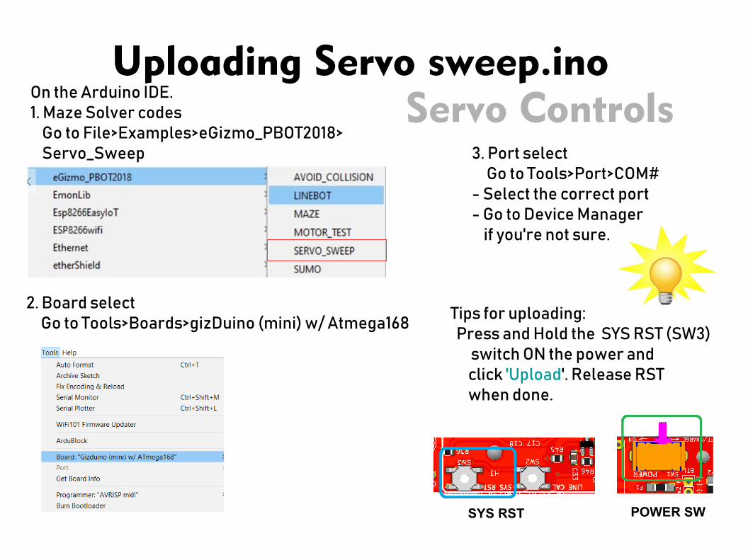
Uploading Servo sweep.inoServo ControlsOn the Arduino IDE.
1. Maze Solver codes Go to File>Examples>eGizmo_PBOT2018> Servo_Sweep
2. Board select Go to Tools>Boards>gizDuino (mini) w/ Atmega168
3. Port select Go to Tools>Port>COM#- Select the correct port- Go to Device Manager if you're not sure.
Tips for uploading: Press and Hold the SYS RST (SW3) switch ON the power and click 'Upload'. Release RST when done.
SYS RST POWER SW

SERVO SYNTAXSYNTAX
PBOT.SERVO(whichSERVO,pulsewidth);where: Whichservo = 1 to 4, ignore other values Pulsewidth = 0 to 180 (degrees) - value less than 500 stops the Servo PWM generator - the pulsewidth converted to degrees from 0 to 180 (default)
EXAMPLES;
PBOT.SERVO(1, 15);delay(1000);PBOT.SERVo(1, 90);delay(1000);

Arduino Shield Accessible Pins
IO0 to IO17 (18 Digital Pins)A0-A3 (4 Analog Input pins)* A4 and A5 are used
Where you can add Bluetooth Shield or otherInterface shields.

Website: e-gizmo.net Egizmo Tech blog: e-gizmo.com/wp Facebook: eGizmoMechatronix Youtube Channel: e-Gizmo Mechatronix Central
For more info.