Embed Size (px)
DESCRIPTION
Manual de ingeniería civil
Citation preview

Guide Specification forHigh Performance Concrete for Bridges
Michael A. Caldarone, Peter C. Taylor,Rachel J. Detwiler, Shrinivas B. Bhide
Guide Specification forHigh-Performance Concretefor Bridges
FIRST EDITION
by Michael A. Caldarone, Peter C. Taylor, Rachel J. Detwiler, and Shrinivas B. Bhidé
An organization of cement com-panies to improve and extend the uses of portland cement and con-crete through market development,engineering, research, education,and public affairs work.
Portland Cement Association5420 Old Orchard RoadSkokie, Illinois 60077-1083847.966.6200 Fax 847.966.9781www.cement.org

Guide Specification for High-Performance Concrete for Bridges
ii
KEYWORDS: AASHTO, abrasion resistance, admixtures, aggregates, air-entrained concrete, air void analyzer, alkali-carbonatereactivity, alkali-silica reactivity, ASR, ASTM, bridge, cement, cementitious materials, chemical admixtures, chloride ion pene-tration, cold weather, compressive strength, consistency, corrosion inhibitors, crack control, cracking, creep, curing, D-cracking,deck, durability, finishing, flowing concrete, footing, freeze/thaw durability, fly ash, girder, guide specification, high-performanceconcrete, hot weather, mass concrete, mixture proportioning, modulus of elasticity, pier, placing, portland cement concrete,performance, properties, quality assurance, quality control, ready mixed concrete, scaling resistance, SCC, self consolidatingconcrete, shrinkage, silica fume, slag cement, spacing factor, standards, structural concrete, sulfate resistance, supplementarycementitious materials, temperature control, tests, trial batches, volume changes, and water-cementitious materials ratio, w/cm.
ABSTRACT: This guide specification is intended to serve as a guide for developing specifications for all high performanceconcretes supplied for highway bridges, whether produced by a ready mix supplier, a general contractor, or in a permanent plantof a precast concrete manufacturer. For the purposes of this specification, high performance concrete (HPC) is considered asconcrete engineered to meet specific needs of a project; including: mechanical, durability, or constructability properties. Thedocument provides mandatory language that the specifier can cut and paste into project specifications. It also includes guidanceon what characteristics should be specified in a given case, and what performance limit is needed to ensure satisfactoryperformance for a given element or environment.
REFERENCE: Michael A. Caldarone, Peter C. Taylor, Rachel J. Detwiler, and Shrinivas B. Bhidé; Guide Specification for High-Performance Concrete for Bridges, EB233, 1st edition, Portland Cement Association, Skokie, Illinois, USA, 2005, 64 pages.
Cover photo: Confederation Bridge, New Brunswick and Prince Edward Island, Canada, © 2005 Boily.
© Portland Cement Association 2005
All rights reserved. PCA grants permission to include any or all parts of this document in specific project specifications.
ISBN 0-89312-245-9
Portland Cement Association ("PCA") is a not-for-profit organization and provides this publication solely for the continuingeducation of qualified professionals. THIS PUBLICATION SHOULD ONLY BE USED BY QUALIFIED PROFESSIONALS whopossess all required license(s), who are competent to evaluate the significance and limitations of the information providedherein, and who accept total responsibility for the application of this information. OTHER READERS SHOULD OBTAINASSISTANCE FROM A QUALIFIED PROFESSIONAL BEFORE PROCEEDING.
PCA AND ITS MEMBERS MAKE NO EXPRESS OR IMPLIED WARRANTY WITH RESPECT TO THIS PUBLICATION OR ANYINFORMATION CONTAINED HEREIN. IN PARTICULAR, NO WARRANTY IS MADE OF MERCHANTABILITY OR FITNESS FOR APARTICULAR PURPOSE. PCA AND ITS MEMBERS DISCLAIM ANY PRODUCT LIABILITY (INCLUDING WITHOUT LIMITATIONANY STRICT LIABILITY IN TORT) IN CONNECTION WITH THIS PUBLICATION OR ANY INFORMATION CONTAINED HEREIN.
Research Index No. 02-05EB233 R&D Serial No. 2755
WARNING: Contact with wet (unhardened) concrete, mortar, cement, or cement mixtures can cause SKIN IRRITATION,SEVERE CHEMICAL BURNS (THIRDDEGREE), or SERIOUS EYE DAMAGE. Frequent exposure may be associated with irri-tant and/or allergic contact dermatitis. Wear waterproof gloves, a long-sleeved shirt, full-length trousers, and proper eyeprotection when working with these materials. If you have to stand in wet concrete, use waterproof boots that are highenough to keep concrete from flowing into them. Wash wet concrete, mortar, cement, or cement mixtures from yourskin immediately. Flush eyes with clean water immediately after contact. Indirect contact through clothing can be asserious as direct contact, so promptly rinse out wet concrete, mortar, cement, or cement mixtures from clothing. Seekimmediate medical attention if you have persistent or severe discomfort.

iii
Table of Contents
Title Page . . . . . . . . . . . . . . . . . . . . . . . . . . . . . . . . . . . . . . . . . . . . . . . . . . . . . . . . . . . . . . . . . . . . . . . . . . i
Keywords, Abstract, and Reference . . . . . . . . . . . . . . . . . . . . . . . . . . . . . . . . . . . . . . . . . . . . . . . . . . . . . . ii
About the Authors . . . . . . . . . . . . . . . . . . . . . . . . . . . . . . . . . . . . . . . . . . . . . . . . . . . . . . . . . . . . . . . . . . . vi
Acknowledgments . . . . . . . . . . . . . . . . . . . . . . . . . . . . . . . . . . . . . . . . . . . . . . . . . . . . . . . . . . . . . . . . . . . vi
Introduction . . . . . . . . . . . . . . . . . . . . . . . . . . . . . . . . . . . . . . . . . . . . . . . . . . . . . . . . . . . . . . . . . . . . . . . . 1
1.0 Scope. . . . . . . . . . . . . . . . . . . . . . . . . . . . . . . . . . . . . . . . . . . . . . . . . . . . . . . . . . . . . . . . . . . . . . . . . . 2
2.0 References . . . . . . . . . . . . . . . . . . . . . . . . . . . . . . . . . . . . . . . . . . . . . . . . . . . . . . . . . . . . . . . . . . . . . . 2
2.1 American Association of State Highway and Transportation Officials (AASHTO) . . . . . . . . . . . . . . . . 2
2.2 American Society for Testing and Materials International (ASTM International) . . . . . . . . . . . . . . . . . 3
2.3 U.S. Department of Transportation, Federal Highway Administration . . . . . . . . . . . . . . . . . . . . . . . . 4
2.4 American Concrete Institute (ACI) . . . . . . . . . . . . . . . . . . . . . . . . . . . . . . . . . . . . . . . . . . . . . . . . . . 4
2.5 Portland Cement Association (PCA) . . . . . . . . . . . . . . . . . . . . . . . . . . . . . . . . . . . . . . . . . . . . . . . . . 5
2.6 Precast/Prestressed Concrete Institute (PCI). . . . . . . . . . . . . . . . . . . . . . . . . . . . . . . . . . . . . . . . . . . . 5
2.7 National Ready Mixed Concrete Association (NRMCA) . . . . . . . . . . . . . . . . . . . . . . . . . . . . . . . . . . . 5
3.0 Definitions . . . . . . . . . . . . . . . . . . . . . . . . . . . . . . . . . . . . . . . . . . . . . . . . . . . . . . . . . . . . . . . . . . . . . . 5
4.0 Performance Requirements. . . . . . . . . . . . . . . . . . . . . . . . . . . . . . . . . . . . . . . . . . . . . . . . . . . . . . . . . . 7
4.1 Abrasion Resistance . . . . . . . . . . . . . . . . . . . . . . . . . . . . . . . . . . . . . . . . . . . . . . . . . . . . . . . . . . . . . 7
4.2 Chloride Ion Penetration . . . . . . . . . . . . . . . . . . . . . . . . . . . . . . . . . . . . . . . . . . . . . . . . . . . . . . . . . 7
4.3 Compressive Strength . . . . . . . . . . . . . . . . . . . . . . . . . . . . . . . . . . . . . . . . . . . . . . . . . . . . . . . . . . . 7
4.4 Creep . . . . . . . . . . . . . . . . . . . . . . . . . . . . . . . . . . . . . . . . . . . . . . . . . . . . . . . . . . . . . . . . . . . . . . . 7
4.5 Modulus of Elasticity . . . . . . . . . . . . . . . . . . . . . . . . . . . . . . . . . . . . . . . . . . . . . . . . . . . . . . . . . . . . 7
4.6 Freeze/Thaw Durability. . . . . . . . . . . . . . . . . . . . . . . . . . . . . . . . . . . . . . . . . . . . . . . . . . . . . . . . . . . 7
4.7 Scaling Resistance . . . . . . . . . . . . . . . . . . . . . . . . . . . . . . . . . . . . . . . . . . . . . . . . . . . . . . . . . . . . . . 7
4.8 Shrinkage . . . . . . . . . . . . . . . . . . . . . . . . . . . . . . . . . . . . . . . . . . . . . . . . . . . . . . . . . . . . . . . . . . . . 7
4.9 Sulfate Resistance . . . . . . . . . . . . . . . . . . . . . . . . . . . . . . . . . . . . . . . . . . . . . . . . . . . . . . . . . . . . . . 7
4.10 Consistency . . . . . . . . . . . . . . . . . . . . . . . . . . . . . . . . . . . . . . . . . . . . . . . . . . . . . . . . . . . . . . . . . . 8
4.11 Alkali-Silica Reactivity . . . . . . . . . . . . . . . . . . . . . . . . . . . . . . . . . . . . . . . . . . . . . . . . . . . . . . . . . . . 8
5.0 Materials . . . . . . . . . . . . . . . . . . . . . . . . . . . . . . . . . . . . . . . . . . . . . . . . . . . . . . . . . . . . . . . . . . . . . . . 8
5.1 Cementitious Materials . . . . . . . . . . . . . . . . . . . . . . . . . . . . . . . . . . . . . . . . . . . . . . . . . . . . . . . . . . 8
5.2 Aggregates . . . . . . . . . . . . . . . . . . . . . . . . . . . . . . . . . . . . . . . . . . . . . . . . . . . . . . . . . . . . . . . . . . . 8
5.2.1 Grading and Impurities . . . . . . . . . . . . . . . . . . . . . . . . . . . . . . . . . . . . . . . . . . . . . . . . . . . . . . . 8
5.2.2 Durability . . . . . . . . . . . . . . . . . . . . . . . . . . . . . . . . . . . . . . . . . . . . . . . . . . . . . . . . . . . . . . . . . 8
5.2.2.1 Alkali-Silica Reactivity . . . . . . . . . . . . . . . . . . . . . . . . . . . . . . . . . . . . . . . . . . . . . . . . . . . . 9
5.2.2.2 Alkali-Carbonate Reactivity . . . . . . . . . . . . . . . . . . . . . . . . . . . . . . . . . . . . . . . . . . . . . . . . 9
5.2.2.3 D-Cracking . . . . . . . . . . . . . . . . . . . . . . . . . . . . . . . . . . . . . . . . . . . . . . . . . . . . . . . . . . . . 9
5.3 Water . . . . . . . . . . . . . . . . . . . . . . . . . . . . . . . . . . . . . . . . . . . . . . . . . . . . . . . . . . . . . . . . . . . . . . . 10

iv
5.4 Chemical Admixtures . . . . . . . . . . . . . . . . . . . . . . . . . . . . . . . . . . . . . . . . . . . . . . . . . . . . . . . . . . . . 10
6.0 Submission and Design Requirements . . . . . . . . . . . . . . . . . . . . . . . . . . . . . . . . . . . . . . . . . . . . . . . . . 10
6.1 Concrete Mixture Proportioning. . . . . . . . . . . . . . . . . . . . . . . . . . . . . . . . . . . . . . . . . . . . . . . . . . . . 10
6.2 Concrete Production Facility Certification . . . . . . . . . . . . . . . . . . . . . . . . . . . . . . . . . . . . . . . . . . . . . 10
6.3 Concrete Materials. . . . . . . . . . . . . . . . . . . . . . . . . . . . . . . . . . . . . . . . . . . . . . . . . . . . . . . . . . . . . . 10
6.4 Temperature Control Methods . . . . . . . . . . . . . . . . . . . . . . . . . . . . . . . . . . . . . . . . . . . . . . . . . . . . . 10
6.5 Crack Control Methods . . . . . . . . . . . . . . . . . . . . . . . . . . . . . . . . . . . . . . . . . . . . . . . . . . . . . . . . . . 10
6.6 Curing . . . . . . . . . . . . . . . . . . . . . . . . . . . . . . . . . . . . . . . . . . . . . . . . . . . . . . . . . . . . . . . . . . . . . . . 11
6.7 Quality Control Plan. . . . . . . . . . . . . . . . . . . . . . . . . . . . . . . . . . . . . . . . . . . . . . . . . . . . . . . . . . . . . 11
7.0 Quality Management . . . . . . . . . . . . . . . . . . . . . . . . . . . . . . . . . . . . . . . . . . . . . . . . . . . . . . . . . . . . . . 11
7.1 Quality Assurance . . . . . . . . . . . . . . . . . . . . . . . . . . . . . . . . . . . . . . . . . . . . . . . . . . . . . . . . . . . . . . 11
7.2 Quality Control . . . . . . . . . . . . . . . . . . . . . . . . . . . . . . . . . . . . . . . . . . . . . . . . . . . . . . . . . . . . . . . . 12
8.0 Production of Concrete . . . . . . . . . . . . . . . . . . . . . . . . . . . . . . . . . . . . . . . . . . . . . . . . . . . . . . . . . . . . 12
8.1 General. . . . . . . . . . . . . . . . . . . . . . . . . . . . . . . . . . . . . . . . . . . . . . . . . . . . . . . . . . . . . . . . . . . . . . 12
8.2 Equipment . . . . . . . . . . . . . . . . . . . . . . . . . . . . . . . . . . . . . . . . . . . . . . . . . . . . . . . . . . . . . . . . . . . 13
8.2.1 Within-Batch Uniformity . . . . . . . . . . . . . . . . . . . . . . . . . . . . . . . . . . . . . . . . . . . . . . . . . . . . . . 13
8.2.2 Non-Agitating Equipment. . . . . . . . . . . . . . . . . . . . . . . . . . . . . . . . . . . . . . . . . . . . . . . . . . . . . 13
8.2.3 Agitating Equipment . . . . . . . . . . . . . . . . . . . . . . . . . . . . . . . . . . . . . . . . . . . . . . . . . . . . . . . . 13
8.3 Measurement of Materials . . . . . . . . . . . . . . . . . . . . . . . . . . . . . . . . . . . . . . . . . . . . . . . . . . . . . . . . 13
8.4 Mixing . . . . . . . . . . . . . . . . . . . . . . . . . . . . . . . . . . . . . . . . . . . . . . . . . . . . . . . . . . . . . . . . . . . . . . . 13
8.5 Temperature Control. . . . . . . . . . . . . . . . . . . . . . . . . . . . . . . . . . . . . . . . . . . . . . . . . . . . . . . . . . . . 14
8.5.1 Cold Weather. . . . . . . . . . . . . . . . . . . . . . . . . . . . . . . . . . . . . . . . . . . . . . . . . . . . . . . . . . . . . . 14
8.5.2 Hot Weather . . . . . . . . . . . . . . . . . . . . . . . . . . . . . . . . . . . . . . . . . . . . . . . . . . . . . . . . . . . . . . 14
8.5.3 Control of Temperature Differences . . . . . . . . . . . . . . . . . . . . . . . . . . . . . . . . . . . . . . . . . . . . . 14
8.6 Trial Batches and Mockups . . . . . . . . . . . . . . . . . . . . . . . . . . . . . . . . . . . . . . . . . . . . . . . . . . . . . . . 15
8.7 Site Addition of Materials . . . . . . . . . . . . . . . . . . . . . . . . . . . . . . . . . . . . . . . . . . . . . . . . . . . . . . . . 15
8.8 Delivery Tickets . . . . . . . . . . . . . . . . . . . . . . . . . . . . . . . . . . . . . . . . . . . . . . . . . . . . . . . . . . . . . . . . 15
C1.0 Scope . . . . . . . . . . . . . . . . . . . . . . . . . . . . . . . . . . . . . . . . . . . . . . . . . . . . . . . . . . . . . . . . . . . . . . . . 17
C2.0 References . . . . . . . . . . . . . . . . . . . . . . . . . . . . . . . . . . . . . . . . . . . . . . . . . . . . . . . . . . . . . . . . . . . . . 17
C3.0 Definitions . . . . . . . . . . . . . . . . . . . . . . . . . . . . . . . . . . . . . . . . . . . . . . . . . . . . . . . . . . . . . . . . . . . . . 17
C4.0 Performance Requirements . . . . . . . . . . . . . . . . . . . . . . . . . . . . . . . . . . . . . . . . . . . . . . . . . . . . . . . . 17
C4.1 Abrasion Resistance. . . . . . . . . . . . . . . . . . . . . . . . . . . . . . . . . . . . . . . . . . . . . . . . . . . . . . . . . . . . 21
C4.2 Chloride Ion Penetration . . . . . . . . . . . . . . . . . . . . . . . . . . . . . . . . . . . . . . . . . . . . . . . . . . . . . . . . 21
C4.3 Compressive Strength. . . . . . . . . . . . . . . . . . . . . . . . . . . . . . . . . . . . . . . . . . . . . . . . . . . . . . . . . . 22
C4.4 Creep . . . . . . . . . . . . . . . . . . . . . . . . . . . . . . . . . . . . . . . . . . . . . . . . . . . . . . . . . . . . . . . . . . . . . . 23
C4.5 Modulus of Elasticity . . . . . . . . . . . . . . . . . . . . . . . . . . . . . . . . . . . . . . . . . . . . . . . . . . . . . . . . . . . 24
C4.6 Freeze/Thaw Durability . . . . . . . . . . . . . . . . . . . . . . . . . . . . . . . . . . . . . . . . . . . . . . . . . . . . . . . . . 25
C4.7 Scaling Resistance . . . . . . . . . . . . . . . . . . . . . . . . . . . . . . . . . . . . . . . . . . . . . . . . . . . . . . . . . . . . 27
C4.8 Shrinkage . . . . . . . . . . . . . . . . . . . . . . . . . . . . . . . . . . . . . . . . . . . . . . . . . . . . . . . . . . . . . . . . . . . 27
C4.8.1 Plastic Shrinkage . . . . . . . . . . . . . . . . . . . . . . . . . . . . . . . . . . . . . . . . . . . . . . . . . . . . . . . . . . 28

v
C4.8.2 Autogenous Shrinkage. . . . . . . . . . . . . . . . . . . . . . . . . . . . . . . . . . . . . . . . . . . . . . . . . . . . . . 29
C4.8.3 Drying Shrinkage. . . . . . . . . . . . . . . . . . . . . . . . . . . . . . . . . . . . . . . . . . . . . . . . . . . . . . . . . . 30
C4.9 Sulfate Resistance . . . . . . . . . . . . . . . . . . . . . . . . . . . . . . . . . . . . . . . . . . . . . . . . . . . . . . . . . . . . . 30
C4.10 Consistency . . . . . . . . . . . . . . . . . . . . . . . . . . . . . . . . . . . . . . . . . . . . . . . . . . . . . . . . . . . . . . . . . 32
C4.11 Alkali-Silica Reactivity. . . . . . . . . . . . . . . . . . . . . . . . . . . . . . . . . . . . . . . . . . . . . . . . . . . . . . . . . . 35
C5.0 Materials . . . . . . . . . . . . . . . . . . . . . . . . . . . . . . . . . . . . . . . . . . . . . . . . . . . . . . . . . . . . . . . . . . . . . . 36
C5.1 Cementitious Materials. . . . . . . . . . . . . . . . . . . . . . . . . . . . . . . . . . . . . . . . . . . . . . . . . . . . . . . . . 36
C5.2 Aggregates . . . . . . . . . . . . . . . . . . . . . . . . . . . . . . . . . . . . . . . . . . . . . . . . . . . . . . . . . . . . . . . . . . 36
C5.2.1 Grading and Impurities . . . . . . . . . . . . . . . . . . . . . . . . . . . . . . . . . . . . . . . . . . . . . . . . . . . . . 36
C5.2.2 Durability . . . . . . . . . . . . . . . . . . . . . . . . . . . . . . . . . . . . . . . . . . . . . . . . . . . . . . . . . . . . . . . 37
C5.2.2.1 Alkali-Silica Reactivity. . . . . . . . . . . . . . . . . . . . . . . . . . . . . . . . . . . . . . . . . . . . . . . . . . . 37
C5.2.2.2 Alkali-Carbonate Reactivity . . . . . . . . . . . . . . . . . . . . . . . . . . . . . . . . . . . . . . . . . . . . . . 38
C5.2.2.3 D-Cracking . . . . . . . . . . . . . . . . . . . . . . . . . . . . . . . . . . . . . . . . . . . . . . . . . . . . . . . . . . 38
C5.3 Water . . . . . . . . . . . . . . . . . . . . . . . . . . . . . . . . . . . . . . . . . . . . . . . . . . . . . . . . . . . . . . . . . . . . . . 40
C5.4 Chemical Admixtures. . . . . . . . . . . . . . . . . . . . . . . . . . . . . . . . . . . . . . . . . . . . . . . . . . . . . . . . . . . 40
C6.0 Submission and Design Requirements . . . . . . . . . . . . . . . . . . . . . . . . . . . . . . . . . . . . . . . . . . . . . . . . 41
C6.1 Concrete Mixture Proportioning . . . . . . . . . . . . . . . . . . . . . . . . . . . . . . . . . . . . . . . . . . . . . . . . . . 41
C6.2 Concrete Production Facility Certification. . . . . . . . . . . . . . . . . . . . . . . . . . . . . . . . . . . . . . . . . . . . 42
C6.3 Concrete Materials . . . . . . . . . . . . . . . . . . . . . . . . . . . . . . . . . . . . . . . . . . . . . . . . . . . . . . . . . . . . 42
C6.4 Temperature Control Methods. . . . . . . . . . . . . . . . . . . . . . . . . . . . . . . . . . . . . . . . . . . . . . . . . . . . 42
C6.5 Crack Control Methods . . . . . . . . . . . . . . . . . . . . . . . . . . . . . . . . . . . . . . . . . . . . . . . . . . . . . . . . . 42
C6.6 Curing. . . . . . . . . . . . . . . . . . . . . . . . . . . . . . . . . . . . . . . . . . . . . . . . . . . . . . . . . . . . . . . . . . . . . . 44
C7.0 Quality Management . . . . . . . . . . . . . . . . . . . . . . . . . . . . . . . . . . . . . . . . . . . . . . . . . . . . . . . . . . . . . 45
C7.1 Quality Assurance . . . . . . . . . . . . . . . . . . . . . . . . . . . . . . . . . . . . . . . . . . . . . . . . . . . . . . . . . . . . . 45
C7.2 Quality Control . . . . . . . . . . . . . . . . . . . . . . . . . . . . . . . . . . . . . . . . . . . . . . . . . . . . . . . . . . . . . . . 45
C8.0 Production of Concrete . . . . . . . . . . . . . . . . . . . . . . . . . . . . . . . . . . . . . . . . . . . . . . . . . . . . . . . . . . . 46
C8.1 General . . . . . . . . . . . . . . . . . . . . . . . . . . . . . . . . . . . . . . . . . . . . . . . . . . . . . . . . . . . . . . . . . . . . . 46
C8.2 Equipment. . . . . . . . . . . . . . . . . . . . . . . . . . . . . . . . . . . . . . . . . . . . . . . . . . . . . . . . . . . . . . . . . . . 46
C8.3 Measurement of Materials. . . . . . . . . . . . . . . . . . . . . . . . . . . . . . . . . . . . . . . . . . . . . . . . . . . . . . . 46
C8.4 Mixing . . . . . . . . . . . . . . . . . . . . . . . . . . . . . . . . . . . . . . . . . . . . . . . . . . . . . . . . . . . . . . . . . . . . . 46
C8.5 Temperature Control . . . . . . . . . . . . . . . . . . . . . . . . . . . . . . . . . . . . . . . . . . . . . . . . . . . . . . . . . . . 46
C8.5.1 Cold Weather . . . . . . . . . . . . . . . . . . . . . . . . . . . . . . . . . . . . . . . . . . . . . . . . . . . . . . . . . . . . 47
C8.5.2 Hot Weather . . . . . . . . . . . . . . . . . . . . . . . . . . . . . . . . . . . . . . . . . . . . . . . . . . . . . . . . . . . . . 47
C8.5.3 Control of Temperatures . . . . . . . . . . . . . . . . . . . . . . . . . . . . . . . . . . . . . . . . . . . . . . . . . . . . 49
C8.6 Trial Batches and Mockups . . . . . . . . . . . . . . . . . . . . . . . . . . . . . . . . . . . . . . . . . . . . . . . . . . . . . . 50
C8.7 Site Addition of Materials . . . . . . . . . . . . . . . . . . . . . . . . . . . . . . . . . . . . . . . . . . . . . . . . . . . . . . . 51
C8.8 Delivery Tickets . . . . . . . . . . . . . . . . . . . . . . . . . . . . . . . . . . . . . . . . . . . . . . . . . . . . . . . . . . . . . . . 51

ABOUT THE AUTHORS
Michael A. Caldarone, P.E., is Principal Engineer, Materials Consulting for CTL Group, Skokie, Illinois. He received hisB.S. in Civil Engineering from the University of Illinois at Chicago. He has more than 20 years of broad expertise in mate-rials engineering, with extensive experience in the commercial development, production and utilization of high-performance concrete. He is a registered professional engineer in Illinois.
Peter C. Taylor, Ph.D., P.E., is Principal Engineer and Manager of Materials Consulting for CTL Group, Skokie, Illinois. Hereceived his B.Sc. and Ph.D. in Civil Engineering from the University of Cape Town in South Africa. He has more than 20years experience in consulting and research specializing in materials performance and concrete durability. He is aregistered professional engineer in Illinois.
Rachel Detwiler, Ph.D., P.E., F.A.C.I., is Senior Engineer at Braun Intertec Corp. in Minneapolis, Minnesota. She receivedher B.S., M.S., and Ph.D. from the University of California at Berkeley. She has over 20 years’ experience in consulting,research and development, specializing in concrete materials, performance and durability. She is a registered professionalengineer in Minnesota, Illinois, and Wisconsin.
Shrinivas B. Bhidé, Ph.D., S.E., P.E., is Manager of the Bridge Program at the Portland Cement Association. He receivedhis Bachelor of Technology in Civil Engineering from the Indian Institute of Technology, Bombay, and Master andDoctorate degrees in Structural Engineering from the University of Toronto. He has over 18 years of experience in thedesign of buildings and bridges and is a registered structural and professional engineer in several states.
ACKNOWLEDGMENTS
This publication was prepared for the Engineered Structures Department of the Portland Cement Association, David N.Bilow, Director, with funding through PCA research project 02-05.
The authors wish to thank the following individuals and organizations without whose help this publication would nothave been possible: Caron Johnsen and Dale McFarlane, Portland Cement Association; and Arlene Zapata, Cheryl Taylor,and Deborah Render, consultants for the word processing, cover design, desktop layout and copy editing.
A Special thanks to Ron Burg, Construction Technology Laboratories who provided extensive input during the initialphase of the publication.
Additional thanks for technical assistance, references, and editorial reviews goes to: Bruce Blair, Lafarge North America,Inc.; Bruce Carter, Hanson Permanente Cement; Bill O’Brien, Essroc Cement Corp.; Bill Asselstine, St. Marys Cement Inc.(Canada); Jim Wamelink, Axim Italcementi Group; H. Celik Ozyildirim, Virginia Transportation Research Council; BijanKhaleghi, Washington State Department of Transportation; Paul Fossier, Louisiana Department of Transportation andDevelopment; Ghulam Mujtaba, Florida Department of Transportation; Mary Lou Ralls, Texas Department of Transpor-tation; Jerry Potter and Lou Triandafilou, Federal Highway Administration; Henry Russell, Consultant; Concrete CorrosionInhibitors Association; Slag Cement Association; Silica Fume Association; National Ready Mixed Concrete Association;Precast/Prestressed Concrete Institute; Rico Fung, Cement Association of Canada; Beatrix Kerkhoff, Jamie Farny, TerryCollins, Steve Kosmatka, John Melander, David Bilow, Basile Rabbat, and Paul Tennis, Portland Cement Association.
Thanks also goes The Concrete Society, England for the use of the illustrations on types of cracks; ASTM, AASHTO,Joseph A. Daczko, Master Builders Inc. for the illustration on concrete flow requirements; Casimir Bognacki, the PortAuthority of New York and New Jersey and Colin Lobo, NRMCA for providing the photos of the microwave water contenttest; John Gajda, CTLGroup, for providing the photos of thermal cracking in mass concrete; and ACI for the use of theirmaterial and documents referenced throughout the book. The authors have tried to make this Guide Specification forHigh-Performance Concrete Bridges a concise and current reference on HPC technology. Readers are encouraged tosubmit comments to improve future printings and editions of this book.

1
Introduction
This document is intended to serve as a guide for developing specifications for high performance concrete for
individual projects in all 50 states. It is intended to apply to all high performance concretes supplied for
highway bridges, whether produced by a ready mix supplier, a general contractor, or in a permanent plant
of a precast concrete manufacturer. For the purposes of this specification, high performance concrete (HPC) is
considered as concrete that attains mechanical, durability, or constructability properties exceeding those of normal
concrete. The specific meaning of “high performance” depends on the concrete property or properties under
consideration, which may or may not include strength. Examples of HPC applications in bridges include:
A bridge deck in a northern climate must resist theingress of chloride ions and deicer scaling. If there isconcern about the potential for cracking, a low modulusof elasticity and/or high creep might be specified, inwhich case very high compressive strength might beincompatible with the desired properties. Thus the speci-fication should require a chloride ion penetration andscaling resistance. It should require only the strengthdetermined by the Engineer to be necessary for structuralor operational reasons (e.g., for opening to traffic by acertain time).
A post-tensioned bridge girder could benefit from a highmodulus of elasticity and low creep to minimizedeflections and loss of prestress. It most likely will havehigh strength as a consequence of these properties, orthe designer may specify high strength to allow a moreefficient design, with fewer girders to support the sameload. The specification would thus include criteria formodulus of elasticity, creep, and compressive strength asdictated by the structural design.
A pretensioned, precast girder may be made of self-consolidating concrete. The specification could theninclude a slump flow as well as the modulus of elasticity,creep, and compressive strength requirements. Alterna-tively, the specification could omit a consistency require-
ment and allow the contractor to propose the use of self-consolidating concrete.
A massive bridge pier or foundation must be designed tolimit stresses and cracking due to thermal gradients. Ifhigh strength, particularly high early strength, is specifiedfor this application, the concrete will be more vulnerableto cracking. In this case, high strength is not consistentwith high performance. The specification should not re-quire high strength except at later ages (56 or 90 days),since to limit cracking the concrete most likely willinclude relatively high percentages of supplementarycementitious materials.
The above examples illustrate different criteria that mightbe specified for different applications within the samestructure. The designer must select the criteria that areimportant for the specific application. Specifying addi-tional criteria beyond what is needed is likely to increasecost, make it more difficult to meet the criteria that trulyare important, or result in unanticipated problems. Forexample, high strength, particularly high early strength,frequently is achieved through an increase in the cemen-titious materials content. The resulting heat generatedmay increase the probability of thermal cracking even forsections of moderate size. Or for a bridge deck, forexample, the high stiffness, low creep, and high paste

Guide Specification for High-Performance Concrete for Bridges
2
content that usually accompany high strength may resultin cracking due to autogenous or drying shrinkage. Ifhigh strength was not necessary, or was needed only atlater ages, cracking could be limited by appropriateadjustments to the mix design.
Some criteria (such as chloride penetration) are intendedto be used for prequalification of a given mixture, whileothers (such as compressive strength and air content) areappropriate for use in quality control and acceptancetests. The commentary indicates which of these applica-tions each criterion falls into.
The intended user of this specification is an engineerworking either directly for a state or local highwayauthority or other bridge owner, or for a contractor to astate or local highway authority or bridge owner. Theuser should be familiar with the characteristics of localmaterials. The user also should be aware of local dura-bility concerns that may necessitate special measures toprevent premature deterioration of the concrete. Thisdocument is intended to be modified by the user to suitlocal conditions by inserting relevant clauses into thecontract specification and by inserting numerical valueswhere required.
The specification is accompanied by a Commentary thatprovides explanatory notes, examples and guidance forthe engineer and contractor in achieving the desiredproperties.
Note: Throughout this specification, AASHTO standardsare given as primary, with the corresponding ASTM stan-dard in parentheses. The two types of standards are notdirectly equivalent in every case. The user must select oneor the other. Where only one is given, there is no corre-sponding standard.
1.0 ScopeThis Specification covers the requirements for materials;methods for proportioning, mixing, transporting, placing,finishing, and curing; and quality control and assuranceof high performance concrete bridge elements.
2.0 ReferencesThis specification and its accompanying Commentaryrefer to the following standards, specifications, andpublications. Publication dates deliberately are omittedfrom this listing; the user should refer to the most currentversion.
2.1 American Association of State High-way and Transportation Officials (AASHTO)(www.transportation.org/aashto)
AASHTO M 6, Standard Specification for Fine Aggregatefor Portland Cement Concrete
AASHTO M 80, Standard Specification for CoarseAggregate for Portland Cement Concrete
AASHTO M 85, Standard Specification for PortlandCement
AASHTO M 154, Standard Specification for Air-EntrainingAdmixtures for Concrete
AASHTO M 157, Standard Specification for Ready-MixedConcrete
AASHTO M 194, Standard Specification for ChemicalAdmixtures for Concrete
AASHTO M 240, Standard Specification for BlendedHydraulic Cement
AASHTO M 295, Standard Specification for Coal Fly Ashand Raw or Calcined Natural Pozzolan for Use as aMineral Admixture in Concrete
AASHTO M 302, Standard Specification for GroundGranulated Blast-Furnace Slag for Use in Concrete andMortars
AASHTO M 307, Standard Specification for use of SilicaFume as a Mineral Admixture in Hydraulic-CementConcrete Mortar and Grout
AASHTO T 22, Standard Method of Test for CompressiveStrength of Cylindrical Concrete Specimens
AASHTO T 23, Standard Method of Test for Making andCuring Concrete Test Specimens in the Field
AASHTO T 24, Standard Method of Test for Obtainingand Testing Drilled Cores and Sawed Beams of Concrete
AASHTO T 27, Standard Method of Test for SieveAnalysis of Fine and Coarse Aggregates
AASHTO T 96, Standard Method of Test for Resistance toDegradation of Small-Size Coarse Aggregate by Abrasionand Impact in the Los Angeles Machine
AASHTO T 119, Standard Method of Test for Slump ofHydraulic-Cement Concrete
3
AASTHO T 121, Standard Method of Test for Mass perCubic Meter (Cubic Foot), Yield, and Air Content(Gravimetric) of Concrete
AASHTO T 126, Standard Method of Test for Making andCuring Concrete Test Specimens in the Laboratory
AASHTO T 141, Standard Method of Test for SamplingFreshly Mixed Concrete
AASHTO T 152, Standard Method of Test for Air Contentof Freshly Mixed Concrete by the Pressure Method
AASHTO T 160, Standard Method of Test for LengthChange of Hardened Hydraulic Cement Mortar andConcrete
AASHTO T 161, Standard Method of Test for Resistanceof Concrete to Rapid Freezing and Thawing
AASHTO T 196, Standard Method of Test for Air Contentof Freshly Mixed Concrete by the Volumetric Method
AASHTO T 277, Standard Method of Test for ElectricalIndication of Concrete’s Ability to Resist Chloride IonPenetration
AASHTO T 318-02, Standard Method of Test for WaterContent of Freshly Mixed Concrete Using MicrowaveOven Drying
AASHTO PP 34, Standard Practice for Estimating theCracking Tendency of Concrete
AASHTO LRFD, Bridge Design Specifications, U.S. 3rdEdition, 2004
AASHTO Quality Assurance Guide Specification, 1996
2.2 American Society for Testing andMaterials International (ASTM International)(www.astm.org)ASTM C 31, Standard Practice for Making and CuringConcrete Test Specimens in the Field
ASTM C 33, Standard Specification for ConcreteAggregates
ASTM C 39, Standard Test Method for CompressiveStrength of Cylindrical Concrete Specimens
ASTM C 42, Standard Test Method for Obtaining andTesting Drilled Cores and Sawed Beams of Concrete
Guide Specification for High-Performance Concrete for Bridges
ASTM C 94, Standard Specification for Ready-MixedConcrete
ASTM C 131, Standard Test Method for Resistance toDegradation of Small-Size Coarse Aggregate by Abrasionand Impact in the Los Angeles Machine
ASTM C 136, Standard Test Method for Sieve Analysis ofFine and Coarse Aggregates
ASTM C 138, Standard Test Method for Density (UnitWeight), Yield, and Air Content (Gravimetric) of Concrete
ASTM C 143, Standard Test Method for Slump ofHydraulic-Cement Concrete
ASTM C 150, Standard Specification for Portland Cement
ASTM C 157, Standard Test Method for Length Changeof Hardened Hydraulic-Cement Mortar and Concrete
ASTM C 172, Standard Practice for Sampling FreshlyMixed Concrete
ASTM C 173, Standard Test Method for Air Content ofFreshly Mixed Concrete by the Volumetric Method
ASTM C 192, Standard Practice for Making and CuringConcrete Test Specimens in the Laboratory
ASTM C 231, Standard Test Method for Air Content ofFreshly Mixed Concrete by the Pressure Method
ASTM C 260, Standard Specification for Air-EntrainingAdmixtures for Concrete
ASTM C 295, Standard Guide for PetrographicExamination of Aggregates for Concrete
ASTM C 403, Standard Test Method for Time of Settingof Concrete Mixtures by Penetration Resistance
ASTM C 441, Standard Test Method for Effectiveness ofPozzolans or Ground Blast-Furnace Slag in PreventingExcessive Expansion of Concrete Due to the Alkali-SilicaReaction
ASTM C 457, Standard Test Method for MicroscopicalDetermination of Parameters of the Air-Void System inHardened Concrete

Guide Specification for High-Performance Concrete for Bridges
4
ASTM C 469, Standard Test Method for Static Modulusof Elasticity and Poisson’s Ratio of Concrete inCompression
ASTM C 494, Standard Specification for ChemicalAdmixtures for Concrete
ASTM C 512, Standard Test Method for Creep ofConcrete in Compression
ASTM C 595, Standard Specification for BlendedHydraulic Cements
ASTM C 618, Standard Specification for Coal Fly Ash andRaw or Calcined Natural Pozzolan for Use in Concrete
ASTM C 666, Standard Test Method for Resistance ofConcrete to Rapid Freezing and Thawing
ASTM C 672, Standard Test Method for ScalingResistance of Concrete Surfaces Exposed to DeicingChemicals
ASTM C 779, Standard Test Method for AbrasionResistance of Horizontal Concrete Surfaces
ASTM C 856, Standard Practice for PetrographicExamination of Hardened Concrete
ASTM C 944, Standard Test Method for AbrasionResistance of Concrete or Mortar Surfaces by theRotating-Cutter Method
ASTM C 989, Standard Specification for GroundGranulated Blast-Furnace Slag for Use in Concrete andMortars
ASTM C 1012, Standard Test Method for Length Changeof Hydraulic-Cement Mortars Exposed to a SulfateSolution
ASTM C 1017, Standard Specification for ChemicalAdmixtures for Use in Producing Flowing Concrete
ASTM C 1064, Standard Test Method for Temperature ofFreshly Mixed Portland Cement Concrete
ASTM C 1074, Standard Practice for Estimating ConcreteStrength by the Maturity Method
ASTM C 1105, Standard Test Method for Length Changeof Concrete Due to Alkali-Carbonate Rock Reaction
ASTM C 1157, Standard Performance Specification forHydraulic Cement
ASTM C 1202, Standard Test Method for ElectricalIndication of Concrete’s Ability to Resist Chloride IonPenetration
ASTM C 1240, Standard Specification for Silica FumeUsed in Cementitious Mixtures
ASTM C 1260, Standard Test Method for Potential AlkaliReactivity of Aggregate (Mortar-Bar Method)
ASTM C 1293, Standard Test Method for Determinationof Length Change of Concrete Due to Alkali-SilicaReaction
ASTM C 1567, Standard Test Method for Determiningthe Potential Alkali-Silica Reactivity of Combinations ofCementitious Materials and Aggregate (AcceleratedMortar-Bar Method)
ASTM C 1582, Standard Specification for Admixtures toInhibit Chloride-Induced Corrosion of Reinforcing Steel inConcrete
ASTM C 1602, Standard Specification for Mixing WaterUsed in the Production of Hydraulic Cement Concrete
2.3 U.S. Department of Transportation,Federal Highway Administration (FHWA)(www.fhwa.dot.gov)FP-03, Standard Specifications for Construction of Roadsand Bridges on Federal Highway Projects
FHWA High Performance Concrete Tool Kit, U.S.Department of Transportation, Federal HighwayAdministration, Publication NO. FHWA-RD-97-097, 30May 1997.
2.4 American Concrete Institute (ACI)(www.aci-int.org)ACI 121R, Quality Assurance Systems for ConcreteConstruction
ACI 201.2R, Guide to Durable Concrete
ACI 207.1R, Mass Concrete
ACI 207.2R, Effect of Restraint, Volume Change, andReinforcement on Cracking of Mass Concrete
ACI 207.4R, Cooling and Insulating Systems for MassConcrete

5
ACI 209R, Prediction of Creep, Shrinkage, andTemperature Effects in Concrete Structures
ACI 211.1, Standard Practice for Selecting Proportions forNormal, Heavyweight, and Mass Concrete
ACI 211.2, Standard Practice for Selecting Proportions forStructural Lightweight Concrete
ACI 211.3R, Guide for Selecting Proportions of No-SlumpConcrete
ACI 211.4R, Guide for Selecting Proportions for High-Strength Concrete with Portland Cement and Fly Ash
ACI 224R, Control of Cracking in Concrete Structures
ACI 232.1R, Use of Raw or Processed Natural Pozzolansin Concrete
ACI 232.2R, Use of Fly Ash in Concrete
ACI 233R, Slag Cement in Concrete and Mortar
ACI 234, Silica Fume in Concrete
ACI 301, Standard Specification for Structural Concrete
ACI 302.1R, Guide for Concrete Floor and SlabConstruction
ACI 304R, Guide for Measuring, Mixing, Transporting,and Placing Concrete
ACI 305R, Hot Weather Concreting
ACI 306R, Cold Weather Concreting
ACI 308, Standard Practice for Curing Concrete
ACI 308.1, Standard Specification for Curing Concrete
ACI 309R, Guide for Consolidation of Concrete
ACI 318, Building Code Requirements for StructuralConcrete
ACI 345, Guide for Concrete Highway Bridge DeckConstruction
ACI 363R, State of the Art Report on High-StrengthConcrete
ACI 363.2, Guide to Quality Control and Testing of High-Strength Concrete
Guide Specification for High-Performance Concrete for Bridges
2.5 Portland Cement Association (PCA)(www.cement.org)PCA EB001, Design and Control of Concrete Mixtures
PCA IS415, Guide Specification for Concrete Subject toAlkali-Silica Reactions
2.6 Precast/Prestressed Concrete Institute(PCI) (www.pci.org)PCI MNL-116, Manual for Quality Control for Plants andProduction of Structural Precast Concrete Products
PCI MNL-133, Bridge Design Manual
PCI TR-6-03, Interim Guidelines for the Use of Self-Consolidating Concrete in PCI Member Plants
PCI TM-103, Quality Control Technician/Inspector Level IIITraining Manual
2.7 National Ready Mixed ConcreteAssociation (NRMCA) (www.nrmca.org)NRMCA Publication 190, Guideline Manual for QualityAssurance Quality Control
NRMCA, Quality Control Manual
3.0 DefinitionsBridge: A structure including supports erected over adepression or an obstruction, such as water, highway, orrailway, and having a track or passageway for carryingtraffic or other moving loads, and having an openingmeasured along the center of the roadway of more than20 ft (6.5 m) between undercopings of abutments orspring lines of arches, or extreme ends of openings formultiple boxes; it also may include multiple pipes, wherethe clear distance between openings is less than half ofthe smaller contiguous opening.
Cementitious materials: Portland cements, blendedcements, and supplementary cementitious materials (e.g.,fly ash, slag cement, silica fume, and calcined clay) usedin concrete and masonry construction.
Cold weather: A period when, for more than threeconsecutive days, the following conditions exist: (1) theaverage daily air temperature is less than 40°F (5°C) and(2) the air temperature is not greater than 50°F (10°C)for more than one-half of any 24-hr period. The average

Guide Specification for High-Performance Concrete for Bridges
6
daily temperature is the mean of the highest and thelowest temperatures occurring during the period frommidnight to midnight.
Consistency: The relative mobility or ability of freshlymixed concrete or mortar to flow; the usual measure-ments are slump for concrete, flow for mortar or grout,and penetration resistance for neat cementitious paste.
Contract: The written agreement executed between theOwner and the Contractor that sets forth the obligationsof the parties including but not limited to the perfor-mance of the work, furnishing of materials and labor,and basis of payment.
Contractor: Any individual, partnership, corporation, orjoint venture with whom the Owner enters into agree-ment for construction of the work under the contractdocuments.
Creep: Time-dependent deformation due to sustainedload.
Curing: The maintenance of satisfactory moisture andtemperature in concrete during its early stages so thatdesired properties may develop.
Engineer: The registered engineer designated by theOwner as the accepting authority responsible for issuingthe project specification or administering work under thecontract documents.
Flowing concrete: Concrete that is characterized by aslump greater than 71⁄2 in. (190 mm) while remainingcohesive.
High performance concrete (HPC): Concrete engi-neered to meet specific needs of a project; including:mechanical, durability, or constructability properties.
Hot weather: A period when, for more than threeconsecutive days, the following conditions exist: (1) theaverage daily air temperature is greater than 77°F (25°C)and (2) the air temperature for more than one-half of any24-hr period is not less than 85°F (30°C). The averagedaily temperature is the mean of the highest and thelowest temperatures occurring during the period frommidnight to midnight.
Inspector: The Engineer’s or Owner’s authorized repre-sentative who is assigned to make detailed inspections ofthe quality and quantity of the work and its conformanceto the provisions of the Contract.
Mass concrete: A volume of concrete with dimensionslarge enough to require that measures be taken to copewith the generation of heat and temperature gradientsfrom hydration of the cementitious materials, and atten-dant volume change.
Owner: The local, state, or federal highway agency orother public or private entity that will take possession ofthe bridge on completion or upon transfer.
Quality assurance: The planned activities and system-atic actions necessary to provide adequate confidence tothe Owner and other parties that the products or serviceswill perform their intended functions. Quality assurance isa management tool.
Quality control: Actions related to the physical char-acteristics of the materials, processes, and services whichprovide a means to measure and control the characteris-tics to predetermined quantitative criteria. Quality controlis a production tool.
Self-consolidating concrete (SCC): Highly flow-able, non-segregating concrete that can spread intoplace, fill the formwork, and encapsulate the reinforce-ment under its own weight without any mechanicalconsolidation.
Subcontractor: Any individual, partnership, corpora-tion, or joint venture with whom the Contractor entersinto agreement for construction of some portion of thework under the contract documents.
Supplementary cementitious materials:Cementitious materials other than portland cements usedin concrete and masonry construction (e.g., slag cement,fly ash, calcined clay, and silica fume).
Water-cementitious materials ratio (w/cm): Theratio of the mass (or weight) of water to the mass (orweight) of all cementitious materials in the concrete.

4.0 Performance RequirementsLaboratory tests conducted to ensure that the proposedmaterials and the proposed mix proportions meet thespecified performance requirements shall be conductedby a laboratory accredited by AASHTO (or equivalent) forthose tests (or in a PCI-certified plant for the compressivestrength and consistency tests).
4.1 Abrasion ResistanceFor bridge decks or surface courses, aggregates knownto polish shall not be used, or the coarse aggregate shallbe tested according to AASHTO T 96 (ASTM C 131). Theresult shall not exceed_______%.
4.2 Chloride Ion Penetration4x8-in. (100x200-mm) concrete cylinders shall be ______cured to an age of ______ and tested in accordance withAASHTO T 277 (ASTM C 1202). The charge passed in sixhours shall not exceed _____ coulombs.
4.3 Compressive StrengthThe concrete shall meet all of the requirements given inTable 4.3-1 for compressive strength as tested in accor-dance with AASHTO T 22. Specimens may be either 4x8-in. (100x200-mm) or 6x12-in. (150x300-mm) cylinders.
7
Guide Specification for High-Performance Concrete for Bridges
Compressivestrength
Age at test fordesign strength Curing
Table 4.3-1 Required Minimum Compressive Strengths
CuringAge atloading
Creepcoefficient
Moist cure after de-molding until age 7 days
Table 4.4-1 Maximum Creep Coefficient
4.4 CreepThe concrete shall meet the requirements for creep astested in accordance with ASTM C 512. Specimens shallbe 6x12-in. (150x300-mm) cylinders. Store at 50% RH at73°F (23°C) until test. Age at loading, and maximumcreep coefficient shall be as shown in Table 4.4-1. Load-ing shall continue for 180 days.
4.5 Modulus of ElasticityThe concrete shall meet the requirements for modulus ofelasticity as tested in accordance with ASTM C 469 andshown in Table 1. Specimens may be either 4x8-in.(100x200-mm) or 6x12-in. (150x300-mm) cylinders moistcured (100% RH at 73.4±3.0°F [23.0±1.7°C]) until age oftesting.
Modulus of elasticity Age at test
28 days
56 days
Table 4.5-1 Required Minimum Modulus of Elasticity
4.6 Freeze/Thaw DurabilityThe concrete shall have a durability factor of at least_____% when tested in accordance with AASHTO T 161,Procedure A (ASTM C 666, Procedure A), except that theage at testing shall be 56 days. Specimens shall be prismsat least 3 in. (75 mm) but not more than 5 in. (125 mm)in width or depth and at least 11 in. (280 mm) but notmore than 16 in. (400 mm) in length.
4.7 Scaling ResistanceThe concrete shall have a visual rating not greater than__ when tested in accordance with ASTM C 672, exceptthat the specimens shall be ______ cured to age _______before commencement of the 14-day drying period.
4.8 ShrinkageThe drying shrinkage of the concrete when tested inaccordance with AASHTO T 160 (ASTM C 157) shall notexceed _______________________. Specimens shall bemoist cured until the age of ______ and shrinkage shallbe monitored for 180 days thereafter. The baselinecomparator measurement shall be taken at 24 hoursafter casting.
4.9 Sulfate ResistanceThe sulfate exposure for this Work has been determinedto be _______________. The combination of cementi-tious materials in the proportions proposed shall havesulfate resistance at least equivalent to that of Type __cement and the water-cementitious materials ratio shallnot exceed ___.

Guide Specification for High-Performance Concrete for Bridges
8
4.10 ConsistencyConcrete of conventional consistency — Theconcrete shall have a slump not less than ___ nor morethan ___ as measured in accordance with AASHTO T 119(ASTM C 143).
Self-consolidating concrete (SCC)— The concreteshall be classified as self-consolidating concrete and shallbe produced such that it can be placed and consolidatedwithout vibration and without segregation. The slumpflow1 shall be not less than ___ nor more than ___.
4.11 Alkali-Silica ReactivityThe aggregates shall be evaluated for potentially delete-rious alkali-silica reactivity and mitigating measures takenif necessary, as described in Section 5.2.2.1.
5.0 Materials
5.1 Cementitious MaterialsPortland cement shall conform to the requirements ofAASHTO M 85 (ASTM C 150) or ASTM C 1157 for thespecified type, including the optional requirement forearly stiffening. Blended cement shall conform to therequirements of AASHTO M 240 (ASTM C 595) or ASTMC 1157 for the specified type, including the optionalrequirement for early stiffening. Supplementary cementi-tious materials not incorporated into the blended cementshall conform to the relevant standards as follows:
• Fly ash and natural pozzolans shall conform to the re-quirements of AASHTO M 295 (ASTM C 618) for thespecified class.
• Slag cement shall conform to the requirements ofAASHTO M 302 (ASTM C 989) for the specified grade.
• Silica fume shall conform to the requirements ofAASHTO M 307(ASTM C 1240).
For concrete exposed to sulfate attack, the proposedcombination of cementitious materials shall meet therequirements of Section 4.9.
Concrete subject to applications of deicing salts shall berestricted to the following maximum limits on the totalquantity of supplementary cementitious materials, in-
cluding supplementary cementitious materials incorpo-rated in blended cement:
• Fly ash or other pozzolans up to 25% by mass ofcementitious materials
• Slag cement up to 50% by mass of cementitious mate-rials
• Silica fume up to 10% by mass of cementitious mate-rials
• Mixtures of silica fume, fly ash or other pozzolans, andslag cement up to 50% by mass of cementitious mate-rials, with no more than 10% being silica fume and nomore than 25% being fly ash
• Mixtures of fly ash or other pozzolans, and silica fumeup to 35% by mass of cementitious materials, with nomore than 10% being silica fume and no more than25% being fly ash
5.2 Aggregates
5.2.1 Grading and Impurities
Fine and coarse aggregates shall conform to the require-ments of AASHTO M 6 and M 80 (ASTM C 33), exceptthat the soundness requirement shall be waived.
5.2.2 Durability
Unless the performance history of the aggregate isknown, it shall be tested to determine its potential for:
• Alkali-silica reactivity
• Alkali-carbonate reactivity
• D-cracking
An aggregate shall be considered to have an acceptableperformance history provided the field concrete madefrom it is at least 15 years old, the cementitious materialsused are comparable (particularly with regard to alkalicontent and use of supplementary cementitious mate-rials), and the exposure conditions are at least as severeas those in the proposed project. Petrographic examina-tion of the field concrete by ASTM C 856 shall be con-ducted to verify satisfactory performance. A copy of thepetrographer’s report shall be submitted to the Engineer.The aggregate shall be approved by the Engineer beforeit is used in the project.
1 Aggoun, S., Kheirbek, A., Kadri, E.H., and Duval, R., Study of the Flow of Self-compacting Concretes, First North American Conference on theDesign and Use of Self-Consolidating Concrete, 12-13 November 2002, Center for Advanced Cement-Based Materials, NorthwesternUniversity, Evanston, IL, pp. 259-265.

9
Test data for comparable aggregate from the samequarry are acceptable for this purpose.
If any of these criteria cannot be met by an acceptablefield history, the aggregate must be tested as describedin the following sections.
5.2.2.1 Alkali-Silica Reactivity
If an acceptable field performance history is not available,representative samples of siliceous fine and coarse aggre-gates proposed for use on the project shall be evaluatedpetrographically in accordance with ASTM C 295 and bythe mortar bar test, ASTM C 1260.
Aggregate evaluated in accordance with ASTM C 295and determined to contain more than the followingquantities of reactive constituents, expressed as percentby mass, shall be considered potentially reactive2:
• Optically strained, microfractured, or microcrystallinequartz exceeding 5.0%
• Chert or chalcedony exceeding 3.0%
• Tridymite or crystobalite exceeding 1.0%
• Opal exceeding 0.5%
• Natural volcanic glass in volcanic rocks exceeding 3.0%
Aggregate tested in accordance with ASTM C 1260 andexhibiting mean mortar bar expansions at 14 days greaterthan 0.10% shall be considered potentially reactive.
Aggregates considered potentially reactive by either ofthe above methods may be further evaluated by ASTM C1293. Aggregates exhibiting expansions greater than0.04% at 1 year shall be considered potentially reactive.Aggregates exhibiting expansions no more than 0.04%and demonstrating no prior evidence of reactivity in thefield shall be considered innocuous.
If an aggregate is determined to be potentially reactive inaccordance with the above protocol, or if the fieldperformance of the aggregate indicates that it is reactiveregardless of the results of any of the above tests, anappropriate mitigation measure shall be specified. Theeffectiveness of the mitigation measure shall be verified
Guide Specification for High-Performance Concrete for Bridges
by ASTM C 1567 to limit the 14-day expansion to amaximum of 0.10%.
Data from past field performance and/or ASTM C 1293tests using the same aggregate, if available, also may beused to demonstrate satisfactory performance.
No substitution of any material in the concrete ispermitted without testing to verify its performance withregard to alkali-silica reaction.
5.2.2.2 Alkali-Carbonate Reactivity
Representative samples of fine and coarse aggregatescomprised of calcitic dolomites or dolomitic limestonesproposed for use on the project shall be evaluated petro-graphically in accordance with ASTM C 295. Aggregatescharacterized by relatively large, rhombic crystals ofdolomite set in a finer-grained matrix of calcite, clay andmicrocrystalline quartz shall be considered potentiallyreactive and shall be evaluated in accordance with ASTMC 1105 using the proposed cement-aggregate combina-tions. Cement-aggregate combinations exhibiting meanexpansion values greater than 0.015% at 3 months,0.025% at 6 months, or 0.030% at 1 year shall beconsidered potentially reactive.
Aggregates found by the above measures to bepotentially reactive may be used only when diluted with anonreactive aggregate. The suitability of the mixture ofaggregates shall be verified by ASTM C 1105 to result inmean expansions not greater than 0.015% at 3 months,0.025% at 6 months, or 0.030% at 1 year.
5.2.2.3 D-Cracking
For bridge decks that will be subject to freezing andthawing, coarse aggregates shall be tested forsusceptibility to D-cracking unless their performancehistory is known. Test data or field performance data forcomparable aggregates from the same quarry are accept-able for this purpose. Any of the following test methodsare acceptable:
• Washington Hydraulic Fracture test3
2 Guide Specification for Concrete Subjected to Alkali-Silica Reactions, Portland Cement Association, IS415, September 1998, 8 pages.3 Janssen, Donald J. and Snyder, Mark B., Resistance of Concrete to Freezing and Thawing, SHRP-C-391, Washington, DC: Strategic Highway
Research Program, National Research Council, 1994, 301 pp.

Guide Specification for High-Performance Concrete for Bridges
10
• AASHTO T 161 (ASTM C 666), extended to 350 cycles;the durability factor is calculated from the expansion ofthe specimens.
• Iowa Pore Index Test4,5
Aggregates failing these tests shall not be used.
5.3 WaterMixing water for concrete shall comply with ASTM C1602.
5.4 Chemical AdmixturesChemical admixtures shall comply with AASHTO M 154(ASTM C 260), AASHTO M 194 (ASTM C 494), or ASTMC 1017, as applicable. Corrosion inhibitors also shall betested in accordance with ASTM C 1582.
The manufacturer shall certify that all admixtures containno purposefully added chlorides, and that the chlorideion content of the admixtures in the quantities proposedis below the limits given by ACI 201.2 Guide to DurableConcrete (0.01% by mass of cementitious materials).
6.0 Submission and DesignRequirements
6.1 Concrete Mixture ProportioningThe Contractor shall be responsible for concrete mixtureproportioning. Concrete shall be proportioned to meetthe performance requirements detailed in the contractdocuments and Sections 4 and 5.
Concrete mixture proportions shall be designed inconformance with ACI 211.1, 211.2, 211.3R, or 211.4Rand verified by trial batches.
At least 30 days before delivery of the concrete, themanufacturer of the concrete shall submit to theEngineer a statement detailing the materials, sources,and proportions of materials to be used for each gradeof concrete to be supplied. No substitutions shall beallowed without the approval of the Engineer, who mayrequire a resubmission of test data.
The statement shall include the purchaser’s name, con-tract number, concrete manufacturer’s name, mix designnumber, primary and backup production facility locations,intended mix use, air content, and slump ranges for eachintended use.
6.2 Concrete Production FacilityCertificationThe manufacturer of the concrete shall submit a currentcertification of the concrete production facility, includingthe concrete production facility and delivery fleet asissued by the National Ready Mixed Concrete Association(NRMCA) for the plant(s) proposed for use. For concretebatched for or within a precast concrete plant, submitproof of current certification in the Precast/PrestressedConcrete Institute’s Plant Certification Program.
6.3 Concrete MaterialsTest data for all concrete-making materials shall be pro-vided to the Engineer 60 days prior to the start of theWork. All materials shall be approved by the Engineerbefore being used in the Work. Samples of all concrete-making materials (aggregates, cementitious materials,water, and chemical admixtures) shall be provided whenrequested by the Engineer prior to or during productionof the concrete.
6.4 Temperature Control MethodsDuring hot and cold weather, the methods to be used tocontrol the temperature of the concrete as placed andthe temperature of the in-place concrete during curingshall be submitted to the Engineer by the Contractor.Methods to be used to control the core temperature andtemperature gradients during curing shall be submittedto the Engineer by the Contractor. Refer to Section 8.5for further details and to PCI MNL-116 for standardprocedures for precast concrete manufacturing plants.
6.5 Crack Control MethodsThe method(s) to be used to control cracking due toshrinkage and/or thermal stresses shall be submitted tothe Engineer. All concrete elements with smallest dimen-sion larger than 2 ft. (600 mm) shall require implementa-tion of method(s) to control thermal stresses.
4 Traylor, M.L., Efforts to Eliminate D-Cracking in Illinois, Transportation Research Record, No. 853, 1982, pp. 9-14.5 Marks, V.J. and Dubberke, W., Durability of Concrete and the Iowa Pore Index Test, Transportation Research Record, No. 853, 1982, pp. 25-31.

11
The maximum acceptable crack width at the surface forstructural elements, including decks, columns, beams,parapets, and abutments shall be ______in. (____mm).
The Contractor shall inspect unformed concrete surfacesand identify and record the width, depth, and density (inlinear feet per square foot or linear meters per squaremeter) of cracks after removal of burlap or curing tarpau-lins. Results shall be reported to the Engineer.
6.6 CuringCuring shall be in accordance with FHWA FP-03, Stan-dard Specifications For Construction of Roads and Bridgeson Federal Highway Projects, Section 552.15, and ACI308R, Standard Practice for Curing Concrete. In the eventof a conflict between the two documents, FP-03 shalltake precedence over ACI 308.
The Contractor shall submit written descriptions of themethod(s) to be used for the curing of all bridge ele-ments to the Engineer for review and approval. Hot- andcold-weather curing practices shall be employed whenweather conditions warrant (see definitions of hot andcold weather). See Section 6.4 for temperature controlrequirements. In addition, if cracks appear on the surfaceof the concrete during construction, placement shall bediscontinued until corrective measures are implemented.
Curing shall begin within 15 minutes or 6 ft (1.9 m) offinal finishing.
For concrete to be used in the bridge decks, barrier rails,approach slabs, and barrier slabs, the Contractor shallcomply with ACI 302.1R and ACI 308R. If silica fume, flyash, or slag cement is used, the Contractor shall limitfinishing operations to screeding, bull floating, andgrooving. Continuous fogging above the surface of theconcrete shall be used during the finishing operation andmaintained until the concrete surface can support wetburlap without deformation. Free-standing water shall notbe permitted on the surface of the concrete prior to finalset. As soon as the surface of the concrete will supportwet burlap or cotton mats without deformation, theContractor shall apply wet burlap or wet cotton mats tothe textured concrete surface. The concrete shall remaincontinuously wet with a fog nozzle system or soakerhoses for 7 days and until a compressive strength of 3200psi (22 MPa) is reached. The use of polyethylene sheetingor plastic-coated burlap blankets shall not be permitted.
For concrete intended for use in prestressed concrete orwhen strengths are in excess of 6000 psi, temperatures
Guide Specification for High-Performance Concrete for Bridges
shall be monitored by two recording thermometersshowing the time-temperature relationship per 200 ft (60m) of bed. For girders, one thermometer shall be locatedat the center of gravity of the top flange and one at thecenter of gravity of the bottom flange. For piles, onethermometer shall be located midway between theoutside corners of the pile and the nearest edge of thecenter void. If there is no void, only one thermometershall be provided at the center of gravity of the crosssection. Initial application of heat to accelerate curingshall begin only after the concrete has reached its initialset as determined by ASTM C 403. When used, steamshall be at 100% RH. Application of heat shall not bedirectly on concrete. Concrete temperature shall be in-creased at a rate not exceeding 40°F (22°C) per houruntil the desired concrete temperature is reached. Theconcrete temperature shall not exceed ___°F (___°C).Heat curing may continue until the concrete has reachedthe release strength. The Contractor shall detensionstrands before the internal concrete temperature hasdecreased to 20°F (11°C) less than its maximumtemperature.
6.7 Quality Control PlanSee Section 7.2 for the description of the Quality ControlPlan to be submitted by the Contractor to the Engineer.
7.0 Quality Management
7.1 Quality AssuranceThe Owner or Owner’s representative shall prepare andcarry out a Quality Assurance Plan to assure that the finalproduct will perform its intended function. The QualityAssurance activities shall not relieve the Contractor ofQuality Control responsibilities under the terms of theContract. The Quality Assurance Plan documents theOwner’s quality objectives. At a minimum, the QualityAssurance Plan shall include the following:
• Owner’s policy statement
• Quality objectives
• Scope of work under the Quality Assurance Plan
• Organization and reporting relationships
• Authority and responsibilities of the variousorganizations and contractors
• Description of overall quality assurance system, includ-ing which organizations are required to establish andimplement quality assurance programs

Guide Specification for High-Performance Concrete for Bridges
12
7.2 Quality ControlBefore the start of the work, the Contractor shall submitto the Engineer a written Quality Control Plan in accor-dance with Section 153 of FHWA FP-03, “Standard Spe-cifications for Construction of Roads and Bridges onFederal Highway Projects,” or for precast concrete manu-facturers certified under the PCI Plant Certification Pro-gram, submit applicable sections of the plant QualitySystem Manual. The Quality Control Plan shall include :
• Process control testing:
▲ Materials to be tested.
▲ Tests to be conducted.
▲ Location of samples extracted.
▲ Frequency of testing.
• Inspection and control procedures:
▲ Preparatory phase
| Review all contract requirements.
| Ensure compliance of component materials tocontract requirements.
| Coordinate all submittals.
| Ensure capability of equipment and personnel tocomply with contract requirements.
| Ensure preliminary testing is accomplished.
| Coordinate surveying and staking.
▲ Start-up phase
| Review contract requirements with personnelwho will perform the work.
| Inspect start-up of work.
| Establish standards of workmanship.
| Provide necessary training.
| Establish detailed testing schedule based onproduction schedule.
▲ Production phase
| Conduct inspection during construction to iden-tify and correct deficiencies.
| Inspect completed phases before Owner’s sched-uled acceptance.
| Provide feedback and system changes to preventrepeated deficiencies.
▲ Description of records: List the records to bemaintained.
▲ Personnel qualifications
| Document the name, authority, relevantexperience, and qualifications of person withoverall responsibility for inspection system.
| Document the names, authority, and relevantexperience of all persons directly responsible forinspection and testing.
▲ Subcontractors: Include the work of all subcontrac-tors. Provide details of how each subcontractor willfit into the overall organization of the project, in-cluding lines of communication and authority be-tween contractor and subcontractors, and amongsubcontractors.
The plan may be implemented wholly or in part by aSubcontractor or an independent organization. However,the administration of the program, including compliancewith the plan and its modifications, and the quality ofthe work, remain the responsibility of the Contractor.
The Contractor’s Quality Control program shall be wellmanaged and the testing results shall be representativeof actual operations. All quality control tests, inspectionsand approvals shall be documented by the Contractorand shall be kept on site for the use of the Contractor’spersonnel and shall be immediately available to theOwner’s personnel for quality assurance and audit pur-poses. The Quality Control Plan shall contain sufficientdetail to serve as a reference summary and schedule forall quality testing, inspection and approval processescarried out by the Contractor and its agents.
No portion of the work shall begin until after the QualityControl Plan covering that portion of the work has beenaccepted by the Engineer.
8.0 Production of Concrete
8.1 GeneralThe volume of material in the mixer shall not exceed therated mixing capacity of the drum.
Proper facilities shall be provided to enable inspectionof the quality and quantity of the materials and theprocesses used in the manufacture and delivery of theconcrete. The inspector shall be provided with all reason-able facilities for securing samples to determine whether

13
the concrete and its component materials are beingsupplied in conformance with the specification.
Mixers shall be emptied of wash water and returnedconcrete before charging with a new batch of concrete.The entire contents of the mixer shall be dischargedbefore recharging.
8.2 EquipmentThe concrete production facility and transport equipmentshall conform to the certification requirements of theNational Ready Mixed Concrete Association, the PCI PlantCertification Program, or equivalent. Documentation ofthe certification shall be provided to the Engineer onrequest.
The concrete production facility shall have either radio ortelephone communication with the placement operationpersonnel.
All mixers shall be capable of combining the ingredientsof the concrete into a thoroughly mixed and uniformmass, and of discharging the concrete so that the within-batch uniformity requirements of AASHTO M 157 (ASTMC 94) are met.
8.2.1 Within-Batch Uniformity
Mixing equipment used shall produce uniform concretein accordance with the requirements of AASHTO M 157(ASTM C 94).
The minimum sample size for determination of within-batch uniformity shall be 1 cu ft (30 liters). Samples foruniformity determination shall be taken after dischargeof approximately 15% and 85% of the batch.
8.2.2 Non-Agitating Equipment
Concrete that is completely mixed in a stationary mixermay be transported in non-agitating equipment. Thebodies of such equipment shall be smooth water-tightsteel containers equipped with gates that permit controlof the discharge of the concrete. Covers shall be used toprotect the concrete during inclement weather. The con-crete shall be discharged at the site, without segregation,in a thoroughly mixed and uniform mass so as to meetthe within-batch uniformity requirements of AASHTO M157 (ASTM C 94). Unless approved by the Engineer,discharge of the concrete shall be completed within 30
Guide Specification for High-Performance Concrete for Bridges
minutes after introduction of the mixing water to thecementitious materials and aggregates.
8.2.3 Agitating Equipment
Concrete that is completely mixed in a stationary mixermay be transported in agitator trucks or truck mixers.The equipment shall be operated at the speed of rotationdesignated by the manufacturer of the truck as theagitating speed. The concrete shall be discharged at thesite, without segregation, in a thoroughly mixed anduniform mass, so as to meet the uniformity requirementsof AASHTO M 157 (ASTM C 94). Except as specified forhot weather concrete, and unless approved by theEngineer, discharge of the concrete shall be completedwithin 11⁄2 hours after introduction of the mixing waterto the cement and aggregates.
8.3 Measurement of MaterialsMeasurement of all constituent concrete-making mate-rials used shall be in accordance with AASHTO M 157(ASTM C 94).
When there is evidence of inaccurately produced batchesof concrete, recalibration of the scales and admixturedispensers may be required.
When ice is used as part of the mixing water, the ice shallbe measured by mass.
8.4 MixingMixing equipment shall comply with AASHTO M 157(ASTM C 94).
Mixers shall be rotated at the speed recommended bythe manufacturer of the mixer.
Mixing time shall be measured from the time that all con-crete ingredients are in the mixing unit. The minimummixing time for concrete shall be as recommended by theequipment manufacturer or the minimum time requiredto produce concrete meeting the uniformity acceptancecriteria of AASHTO M 157 (ASTM C 94), whichever isgreater.
Unless otherwise indicated by the mixer manufacturer,when a truck mixer is used for complete mixing and ischarged to its maximum rated mixing capacity, eachbatch of concrete shall be mixed for not less than 70 normore than 100 revolutions of the drum.

Guide Specification for High-Performance Concrete for Bridges
14
After completion of mixing, the truck mixer drum shallbe rotated at the designated agitating speed untildischarge of concrete commences.
When a stationary mixer is used for partial mixing ofconcrete prior to transferring to a truck mixer, the mixingtime shall be no more than is required to intermingle theingredients. After transfer to a truck mixer, further mixingat the designated mixing speed shall be carried out.
For concrete containing silica fume batched separatelyfrom the cement (that is, not a component of blendedcement), the silica fume shall be added to the aggregatewith the cement. Silica fume shall not be placed first inthe mixer. Silica fume shall not be added to the mixer inpulpable bags.
8.5 Temperature ControlThe concrete temperature at the time of discharge fromthe truck shall be at or between 50°F (10°C) and 90°F(32°C). The temperature of the cementitious materialsshall be less than 150°F (65°C) immediately prior tobatching. During curing, the maximum concrete temper-ature shall not exceed _____°F (_____°C) and the mini-mum temperature of concrete shall not fall below 50°F(10°C).
8.5.1 Cold Weather
During cold weather (see Section 3.0 for definition),special precautions shall be employed when producing,placing, finishing and curing the concrete to protect itfrom the effects of cold weather. Method(s) to be usedto control the concrete placement temperature shall besubmitted by the concrete supplier. Method(s) to be usedto control the concrete temperature and temperaturegradients during curing shall be submitted by theContractor.
Water brought into direct contact with the cementitiousmaterials shall have a temperature less than 104°F(40°C). The concrete production facility shall have awater temperature indicator installed such that the batchoperator can ensure that the temperature restrictions aremet for each batch. Provision shall be made for heatingaggregates in the concrete production facility storagebins. Aggregates shall be free of ice, snow, and frozenlumps before being placed in the mixer. The temperatureof concrete shall not be less than 50°F (10°C) at the timeof placement. The mix water and/or aggregates may be
heated to not more than 104°F (40°C). Provision must bemade to ensure that the material is heated evenly beforebeing placed in the mixer.
8.5.2 Hot Weather
Hot weather (see Section 3.0 for definition) concretingpractices shall apply during hot weather (refer to defini-tion of “hot weather”). Precautions shall be employedwhen producing, placing, finishing, and curing theconcrete to protect it from the effects of hot weather.Method(s) to be employed to control the concrete place-ment temperature shall be submitted to the Engineer bythe Contractor. Method(s) to be used to monitor weatherconditions during concrete placement, control plasticshrinkage cracking, and control the concrete temperatureand temperature gradients during curing shall besubmitted to the Engineer by the Contractor.
When ice is added to the concrete, it shall be completelymelted by the time the concrete mixing is completed.Unless approved by the Engineer, when the air tempera-ture exceeds 82°F (28°C) and the concrete temperatureexceeds 77°F (25°C), concrete delivered by means ofagitators or truck mixers shall be discharged within 1 hrafter the introduction of the mixing water.
Plastic shrinkage control procedures shall be employedwhen the evaporation rate of the freshly placed concreteexceeds the bleeding rate. Method(s) to be used shalleffectively reduce the rate of moisture loss from theconcrete surface or replenish moisture to the surface lostto evaporation. Fog spraying, if used, shall be at a ratesufficient to maintain a sheen of moisture on the surface,but no ponding of water. Excess moisture shall not befinished into the concrete. Allow the water to evaporatejust prior to finishing.
8.5.3 Control of Temperature Differences
Unless it can be demonstrated by engineering analysisthat it is not detrimental to the structure, the maximumtemperature differential between the interior and exteriorconcrete shall be limited to 35°F (19°C). For precast prod-ucts that use the addition of heat to accelerate curing,the maximum cooling rate for products that haveachieved transfer or stripping strength is 50°F (28°C)per hour. Standard practices should be followed fortransferring products from forms to storage that havedemonstrated acceptable results.

15
8.6 Trial Batches and MockupsLaboratory trial batches shall be made as a condition offinal approval of the mix design. All specified propertiesshall be verified in accordance with the test methodsprescribed in Section 4.
In addition, the Contractor shall be responsible forconducting a field trial batch of the concrete. At least 60days prior to placing high performance concrete, a full-size trial batch of concrete shall be produced and tested.Field trial batches of concrete shall originate from eachproduction facility that will be used to supply the con-crete. Trial batches shall be delivered to the site of thework as directed by the concrete purchaser. When theconcrete is delivered in a ready mixed concrete truck, thevolume of the trial batch shall be the volume of concretenormally supplied by the truck. Field mockups shall beconstructed as required by the Engineer to verify all tech-niques to be used for transport, placement, consol-idation, finishing, and curing of the concrete member.
When an approved ready mixed concrete operation iscurrently supplying or has supplied a class of concretewithin the last ____ months requiring comparable perfor-mance, permission may be granted by the Engineer touse the concrete mixture proportions from that operationwithout the need for the full range of laboratory or fieldtrial batches provided that:
• There is no change in the source of any material.
• There has been no significant change in quality of theconcrete-making materials.
• The proposed concrete mix design meets all specifiedrequirements.
• The conditions of field placement are substantially thesame as for the previous job.
• Documentation of all test data is submitted to theEngineer.
The Engineer shall indicate in writing which tests are notrequired.
8.7 Site Addition of MaterialsWhen a truck mixer is used at agitating capacity no ad-justment shall be made to the load of concrete.
EITHER: When a truck mixer is used for mixing of theconcrete, no water from the truck water system shall beadded after the initial introduction of the mixing water to
Guide Specification for High-Performance Concrete for Bridges
the load of concrete. Water shall not be added to theload of concrete at any time.
OR: The amount of water added shall be recorded on theconcrete delivery ticket. In no case shall the total amountof water in the concrete be such as to exceed the speci-fied water-cementitious materials ratio.
Water-reducing admixture may be added to the concretewhen the measured slump is less than that specified.
Air-entraining admixture may be added to the concreteprior to discharge to increase the air content to that spe-cified. The use of air-detraining admixtures is expresslyprohibited.
Site introduced admixtures shall be added to the batchby means of a pipe or wand that can introduce theproduct to the center of the drum using an automatedmetering device. Only trained personnel shall be allowedto introduce admixtures at the jobsite. A method state-ment by the contractor for the site addition of admix-tures shall be submitted and a record of jobsite additionsshall be maintained and available at the project site atall times.
When any material is added to the concrete, the concretebatch shall be mixed for an additional 30 revolutions (ormore if necessary) at the designated mixing speed so thatthe uniformity requirements of Annex 1 of AASHTO M157 (ASTM C 94) are met. In this situation it is permis-sible to exceed the maximum of 100 revolutions total.The uniformity shall be monitored before placement ofthe concrete.
8.8 Delivery TicketsWith each batch of concrete, the concrete manufacturershall provide to the Contractor a copy of the deliveryticket, on which shall be printed, stamped, or written thefollowing information:
• Name of concrete manufacturer, and name or numberof concrete production facility
• Serial number of delivery ticket
• Date
• Class or designation of the concrete
• Truck number
• Name of Contractor
• Name and address of project

Guide Specification for High-Performance Concrete for Bridges
16
• Time of batching, or of first mixing of cementitiousmaterials and aggregates
• Time at which concrete discharge must be completed
• Moisture corrections for aggregate moisture
• Quantities of each mixture component
• Total batch volume
• Maximum water that may be added to the mix at theproject
• Quantities of materials added at the site, includingwater and admixtures, if any
• Specified compressive strength (or other specifiedperformance criterion)

17
Commentary on Guide Specification forHigh-Performance Concrete for Bridges
C1.0 ScopeThe Guide Specification provides appropriate wording tospecify each of the following criteria for high performanceconcrete: abrasion resistance, chloride ion penetration,compressive strength, creep, modulus of elasticity, freeze/thaw durability, scaling resistance, shrinkage, sulfate resis-tance, consistency, and alkali-silica reactivity. For a givenbridge element, it is anticipated that the specifier willselect at most four criteria. The performance criteria aregiven in Sections 4.1-4.11 of the specification, with guid-ance in the corresponding sections of the Commentaryfor modifying these criteria to suit local conditions.
Table C1.1 summarizes how to select criteria for variousbridge elements. Table C1.2 summarizes the test methodsand standards discussed in this guide specification.
C2.0 References
C3.0 Definitions
C4.0 Performance RequirementsSpecify only the performance grade required for eachcharacteristic, as additional requirements add to the costof the material without necessarily providing additionalperformance benefits. In some cases, high performanceby one criterion may even detract from the performanceby another criterion. FHWA recommendations for theapplication of HPC Grades are shown in Table C4.0 forreference. In some cases these differ from the recom-mendations of this guide specification.
Note that FHWA’s default age at test is 56 days. Forcertain jobs, other ages, or accelerated curing regimes,may be more appropriate to specify either in addition toor instead of 56 days. If so, they must be explicitly speci-fied. Examples are given in the following sections.

Guide Specification for High-Performance Concrete for Bridges
18
Perf
orm
ance
char
acte
rist
ics
Elem
ent
Dec
kG
ird
erPi
erFo
oti
ng
Abr
asio
nre
sist
ance
Ifab
rasi
onfr
omsn
owpl
ows
isa
conc
ern,
eith
ersp
ecify
abra
sion
resi
stan
cecr
iterio
nfo
rco
ncre
teor
crite
riafo
rag
greg
ate.
Do
not
spec
ify.
Ifab
rasi
ondu
eto
ice
floes
,flo
atin
gde
bris
,or
boat
sis
aco
ncer
n,ei
ther
spec
ifyab
rasi
onre
sist
ance
crite
rion
for
conc
rete
orcr
iteria
for
aggr
egat
e.
Do
not
spec
ify.
Chl
orid
eIo
nPe
netr
atio
nIf
expo
sed
tode
icin
gsa
ltsor
salt
spra
y,sp
ecify
max
imum
limit
onA
ASH
TOT
277.
Ifex
pose
dto
salt
spra
y,sp
ecify
max
imum
limit
onA
ASH
TOT
277.
Ifex
pose
dto
salt
spra
y,sp
ecify
max
imum
limit
onA
ASH
TOT
277.
Do
not
spec
ify.
Com
pres
sive
Stre
ngth
Spec
ifyst
reng
th(s
)and
age(
s)if
the
stru
ctur
albe
havi
orde
pend
son
havi
nga
cert
ain
stre
ngth
;hig
hea
rlyst
reng
thco
uld
incr
ease
risk
ofcr
acki
ng.
Spec
ifyst
reng
ths
for
de-t
ensi
onin
gof
pres
tres
sing
stra
nd,t
rans
port
ofpr
ecas
tel
emen
tsto
site
,and
open
ing
ofbr
idge
totr
affic
.
Spec
ifyst
reng
th(s
)and
age(
s)as
dete
rmin
edby
stru
ctur
alde
sign
.H
igh
stre
ngth
sat
early
ages
may
incr
ease
risk
ofth
erm
alcr
acki
ng.
Spec
ifyst
reng
th(s
)and
age(
s)as
dete
rmin
edby
stru
ctur
alde
sign
.H
igh
stre
ngth
sat
early
ages
may
incr
ease
risk
ofth
erm
alcr
acki
ng.
Cre
epD
ono
tsp
ecify
.Too
low
cree
pm
ayco
ntrib
ute
tocr
acki
ngof
the
deck
.Sp
ecify
max
imum
allo
wab
lecr
eep
toco
ntro
lpre
stre
sslo
sses
and
long
-te
rmde
flect
ions
.
May
spec
ifym
axim
umal
low
able
cree
pto
cont
roll
ong-
term
defle
ctio
ns.
Do
not
spec
ify.
Mod
ulus
ofEl
astic
ityD
ono
tsp
ecify
.Too
high
mod
ulus
ofel
astic
itym
ayco
ntrib
ute
tocr
acki
ngof
the
deck
.
Spec
ifym
inim
umal
low
able
mod
ulus
ofel
astic
ityto
cont
rol
defle
ctio
ns.
May
spec
ifyto
limit
defle
ctio
ns.
Do
not
spec
ify.
Free
ze/T
haw
Dur
abili
tyIf
expo
sed
tofr
eezi
ngan
dth
awin
g,sp
ecify
am
inim
umdu
rabi
lity
fact
orfo
rA
ASH
TOT
161.
Do
not
spec
ify.
Do
not
spec
ifyun
less
the
pier
ispa
rtia
llysu
bmer
ged
inw
ater
orsa
tura
ted
soil
subj
ect
tofr
eezi
ng.
Do
not
spec
ifyun
less
the
foot
-in
gis
insa
tura
ted
soil
subj
ect
tofr
eezi
ng.
Scal
ing
Resi
stan
ceIf
expo
sed
tode
icin
gsa
lts,s
peci
fya
max
imum
visu
alra
ting
onA
STM
C67
2.
Do
not
spec
ify.
Do
not
spec
ify.
Do
not
spec
ify.
Shrin
kage
Do
not
spec
ify.
Do
not
spec
ify.
Do
not
spec
ify.
Do
not
spec
ify.
Sulfa
teRe
sist
ance
Do
not
spec
ify.
Do
not
spec
ify.
Ifex
pose
dto
sulfa
teso
ilsor
grou
nd-
wat
er,s
peci
fyth
atce
men
titio
usm
ater
ial(s
)and
w/c
mm
ust
mee
tre
quire
men
tsfo
rse
verit
yof
expo
sure
.
Ifex
pose
dto
sulfa
teso
ilsor
grou
ndw
ater
,spe
cify
that
cem
entit
ious
mat
eria
l(s)a
ndw
/cm
mus
tm
eet
requ
irem
ents
for
seve
rity
ofex
posu
re.
Con
sist
ency
Allo
wco
ntra
ctor
tose
lect
cons
iste
ncy
toac
hiev
eco
nsol
idat
ion.
Spec
ifyva
riabi
lity
limits
.
Alk
ali-s
ilica
reac
tivity
Ensu
reth
atag
greg
ates
used
are
not
pote
ntia
llyre
activ
e,or
take
appr
opria
teco
ntro
lmea
sure
s.
Tabl
eC
1.0-
1W
hich
Crit
eria
toSp
ecif
yfo
rWhi
chB
ridg
eEl
emen
ts

19
Guide Specification for High-Performance Concrete for Bridges
Application AASHTO ASTM Other
Test methods
Abrasion T 6 C 131, C 779, C 944
Chloride penetration T 277 C 1202
Compressive strength T 22 C 39
Cracking pp 34
Creep C 512
Modulus of elasticity C 469
Freeze thaw T 161 C 666
Salt scaling C 672
Shrinkage T 160 C 157
Sulfate resistance C 1012 ACI 201
Slump T 119 C 143
SCC consistencySlump flow, J-ring, columnsegregation
Alkali silica reactionC 1293, C 1260, C 1567,C 295
Alkali carbonate reaction C 1105, C 295
D-cracking T 161 C 666Iowa Pore Index Test,Washington, HydraulicFracture Test
Air content C 231, C 457 Air void analyzer
Water content T 318
Cement content C 1084
Materials specifications
Water M 157 C 1602
Cement M 85, M 240 C 150, C 595, C 1157
Supplementary cementitiousmaterials
M 295, M 302, M 307 C 618, C 989, C 1240
Aggregates M 6, M 80 C 33
Chemical admixtures M 194, M 154 C 494, C 260, C 1582
Ready-mixed concrete M 157 C 94
Quality
QA QC systems ACI 121, 363
AASHTO QAGS
FHWA FP-03
NRMCA Publication 190
PCI MNL 116
Table C1.0-2. Test Methods and Standards Discussed in this Guide Specification
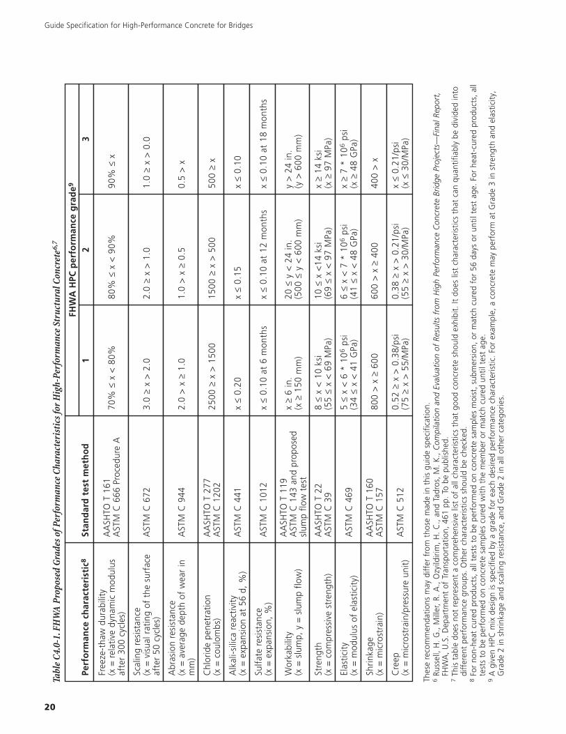
Guide Specification for High-Performance Concrete for Bridges
20
Perf
orm
ance
char
acte
rist
ic8
Stan
dar
dte
stm
eth
od
FHW
AH
PCp
erfo
rman
ceg
rad
e9
12
3
Free
ze-t
haw
dura
bilit
y(x
=re
lativ
edy
nam
icm
odul
usaf
ter
300
cycl
es)
AA
SHTO
T16
1A
STM
C66
6Pr
oced
ure
A70
%≤
x<
80%
80%
≤x
<90
%90
%≤
x
Scal
ing
resi
stan
ce(x
=vi
sual
ratin
gof
the
surf
ace
afte
r50
cycl
es)
AST
MC
672
3.0
≥x
>2.
02.
0≥
x>
1.0
1.0
≥x
>0.
0
Abr
asio
nre
sist
ance
(x=
aver
age
dept
hof
wea
rin
mm
)A
STM
C94
42.
0>
x≥
1.0
1.0
>x
≥0.
50.
5>
x
Chl
orid
epe
netr
atio
n(x
=co
ulom
bs)
AA
SHTO
T27
7A
STM
C12
0225
00≥
x>
1500
1500
≥x
>50
050
0≥
x
Alk
ali-s
ilica
reac
tivity
(x=
expa
nsio
nat
56d,
%)
AST
MC
441
x≤
0.20
x≤
0.15
x≤
0.10
Sulfa
tere
sist
ance
(x=
expa
nsio
n,%
)A
STM
C10
12x
≤0.
10at
6m
onth
sx
≤0.
10at
12m
onth
sx
≤0.
10at
18m
onth
s
Wor
kabi
lity
(x=
slum
p,y
=sl
ump
flow
)
AA
SHTO
T11
9A
STM
C14
3an
dpr
opos
edsl
ump
flow
test
x≥
6in
.(x
≥15
0m
m)
20≤
y<
24in
.(5
00≤
y<
600
mm
)y
>24
in.
(y>
600
mm
)
Stre
ngth
(x=
com
pres
sive
stre
ngth
)A
ASH
TOT
22A
STM
C39
8≤
x<
10ks
i(5
5≤
x<
69M
Pa)
10≤
x<
14ks
i(6
9≤
x<
97M
Pa)
x≥
14ks
i(x
≥97
MPa
)
Elas
ticity
(x=
mod
ulus
ofel
astic
ity)
AST
MC
469
5≤
x<
6*
106
psi
(34
≤x
<41
GPa
)6
≤x
<7
*10
6ps
i(4
1≤
x<
48G
Pa)
x≥
7*
106
psi
(x≥
48G
Pa)
Shrin
kage
(x=
mic
rost
rain
)A
ASH
TOT
160
AST
MC
157
800
>x
≥60
060
0>
x≥
400
400
>x
Cre
ep(x
=m
icro
stra
in/p
ress
ure
unit)
AST
MC
512
0.52
≥x
>0.
38/p
si(7
5≥
x>
55/M
Pa)
0.38
≥x
>0.
21/p
si(5
5≥
x>
30/M
Pa)
x≤
0.21
/psi
(x≤
30/M
Pa)
Tabl
eC
4.0-
1.FH
WA
Prop
osed
Gra
deso
fPer
form
ance
Char
acte
rist
icsf
orH
igh-
Perf
orm
ance
Stru
ctur
alCo
ncre
te6,
7
Thes
ere
com
men
datio
nsm
aydi
ffer
from
thos
em
ade
inth
isgu
ide
spec
ifica
tion.
6Ru
ssel
l,H
.G
.,M
iller
,R.
A.,
Ozy
ildiri
m,
H.
C.,
and
Tadr
os,
M.
K.,
Com
pila
tion
and
Eval
uatio
nof
Resu
ltsfr
omH
igh
Perf
orm
ance
Con
cret
eBr
idge
Proj
ects
—Fi
nalR
epor
t,FH
WA
,U
.S.
Dep
artm
ent
ofTr
ansp
orta
tion,
461
pp.
Tobe
publ
ishe
d.7
This
tabl
edo
esno
tre
pres
ent
aco
mpr
ehen
sive
list
ofal
lcha
ract
eris
tics
that
good
conc
rete
shou
ldex
hibi
t.It
does
list
char
acte
ristic
sth
atca
nqu
antif
iabl
ybe
divi
ded
into
diff
eren
tpe
rfor
man
cegr
oups
.O
ther
char
acte
ristic
ssh
ould
bech
ecke
d.8
For
non-
heat
cure
dpr
oduc
ts,
allt
ests
tobe
perf
orm
edon
conc
rete
sam
ples
moi
st,
subm
ersi
on,
orm
atch
cure
dfo
r56
days
orun
tilte
stag
e.Fo
rhe
at-c
ured
prod
ucts
,al
lte
sts
tobe
perf
orm
edon
conc
rete
sam
ples
cure
dw
ithth
em
embe
ror
mat
chcu
red
until
test
age.
9A
give
nH
PCm
ixde
sign
issp
ecifi
edby
agr
ade
for
each
desi
red
perf
orm
ance
char
acte
ristic
.Fo
rex
ampl
e,a
conc
rete
may
perf
orm
atG
rade
3in
stre
ngth
and
elas
ticity
,G
rade
2in
shrin
kage
and
scal
ing
resi
stan
ce,
and
Gra
de2
inal
loth
erca
tego
ries.

21
Guide Specification for High-Performance Concrete for Bridges
C4.1 Abrasion ResistanceAbrasion resistance is significant for bridge decks thatwill be subjected to the action of truck traffic orsnowplows, and for bridge substructure elements thatwill be in direct contact with ice floes, floating debris,and boat or ship traffic.
In general, good abrasion resistance is achieved by theuse of high-strength concrete and a hard, abrasion-resis-tant aggregate. Proper finishing and curing of theconcrete surface are essential. Specifications are normallybased on requiring a given performance from the aggre-gate and setting a minimum strength. Field tests ofabrasion resistance are not commonly required except fortroubleshooting and evaluation of rain-damagedsurfaces.
Aggregates should be pre-qualified, either based onhistorical performance or by testing. ASTM C 33 imposesa limit of 50% mass loss in the Los Angeles Abrasion test(AASHTO T 96) but this may be considered too high avalue for high performance requirements. As indicated inTable C4.0, the FHWA provides criteria for field testingaccording to ASTM C 944, which is similar to ASTM C779, Procedure B. It gives an indication of the relativewear resistance of concrete.
Figures C4.1-1. Los Angeles abrasion test (AASHTO T 96).Test measures degradation of aggregates resulting from a combination of abrasion, impact, and grinding in a rotating steel drum containing a speci-fied number of steel spheres. As the drum rotates, a shelf plate picks up the sample and the steel spheres, carrying them around until they are droppedto the opposite side of the drum, creating an impact crushing effect. The contents then roll within the drum with an abrading and grinding actionuntil the shelf plate picks up the sample and the steel spheres, and the cycle is repeated. After the prescribed number of revolutions, the contents areremoved from the drum and the aggregate portion is sieved to measure the degradation as percent loss. (left: IMG16950, right: IMG16949)
C4.2 Chloride Ion PenetrationResistance to chloride ion penetration is significant forreinforced and prestressed concrete that will be exposedto chlorides. The most common sources of chlorides fromthe environment are deicing salts and seawater. Chloridesact as catalysts to the corrosion reactions.
If the crack widths are controlled by providing crackcontrol reinforcement as specified in the AASHTO LFRDBridge Design Specifications, the ability of the concreteto protect the steel from corrosion depends on thequality of the concrete and the cover thickness.
A maximum limit of 1500 coulombs (ASTM C 1202) isappropriate for most bridge elements that will beexposed to chlorides. Values of 1500 to 2500 coulombswould be appropriate for superstructure elements notexpected to receive chloride exposure on a continuingbasis. However, note that if deck joints are locateddirectly over elements of the superstructure, eventuallythe joints will leak and salt water will drain onto thesuperstructure. If possible, locate deck joints elsewhere. Ifnot, specify 1500-coulomb concrete throughout. This testis commonly used as an acceptance indicator. It shouldbe noted that the scatter on the test is large, thereforeimposing a limit of less than 1500 coulombs may resultin rejection of acceptable concrete

Elevated curing temperatures increase the perme-ability and diffusivity of concrete even when they donot actually increase its porosity11. However, con-cretes containing supplementary cementitious mate-rials are less sensitive to this effect than portlandcement concretes12.
Virginia DOT has adopted an accelerated curingregime for use with mixtures containing supplemen-tary cementing materials13. Specimens are moistcured for 7 days at room temperature, followed by3 weeks moist at 100°F (38°C). This regime isreported to be equivalent to 6 months normaltemperature curing when tested in accordancewith ASTM C 1202.
C4.3 Compressive StrengthThe required compressive strength(s) must be determinedby the Engineer to ensure that the structure is able towithstand the design load. If control of deflections and/orlimitation of prestress losses is desired, explicitly specifythe modulus of elasticity and the creep. Do not usestrength as a surrogate for either of these properties. Inparticular, strength should never be used as a surro-gate for durability. Although the FHWA performancegrades specify the age of 56 days at which the concreteis to be tested, it may be necessary to specify differentages for some tests, such as to allow for early opening totraffic, or for de-tensioning the strand for precast pre-stressed elements. The Engineer should consider how agiven test age would affect the design calculations andthe behavior of the structure. Compressive strength com-monly is used for quality control and quality assurance.
In general, the use of supplementary cementitious mate-rials reduces the early-age strength and increases thelater-age strength of the concrete as compared with aportland cement-only concrete. However, highly reactivepozzolans such as silica fume and calcined clay mayproduce comparable or even higher strengths at earlyages. Class C fly ash may either increase or reduce early-
Figure C4.2-1. Test setup for the rapid chloride permeability test(RCPT), also called Coulomb or electrical resistance test (ASTM C1202). This test method consists of monitoring the amount of electricalcurrent passed through slices of cores or cylinders during a 6-h period.A potential difference of 60 V dc is maintained across the ends of thespecimen, one of which is immersed in a sodium chloride solution, theother in a sodium hydroxide solution. The total charge passed, incoulombs, is related to the resistance of the specimen to chloride ionpenetration. (IMG16975)
Theoretically, cover thickness and concrete quality can betraded off against one another; however, most currentmodels of service life for concrete structures do not in-clude all of the mechanisms by which chloride ions pene-trate concrete10. Thus it would be prudent to maintainthe cover thicknesses given by the AASHTO LFRD BridgeDesign Specifications and use high performance concreteas needed to prolong the service life.
Class F fly ash, some Class C fly ashes, calcined clay, slagcement, and silica fume all improve concrete’s resistanceto chloride ion penetration. However, all of these requiresufficient curing time to develop the favorable micro-structure that is required. Reducing the water-cementitiousmaterials ratio improves the resistance to chloride ionpenetration for all types of concrete. For bridge decks,latex-modified or other polymer-modified concreteoverlays are an acceptable alternative to lowering thew/cm ratio.
Guide Specification for High-Performance Concrete for Bridges
22
10 Hooton, R. D. and McGrath, P. F., “Issues Related to Recent Developments in Service Life Specifications for Concrete Structures,” ChloridePenetration into Concrete, RILEM, 1995, L.O. Nilsson and J.P. Olivier, Eds., pp. 388-397.
11 Detwiler, Rachel J.; Kjellsen, Knut O., and Gjørv, Odd E., “Resistance to Chloride Intrusion of Concrete Cured at Different Temperatures,” ACIMaterials Journal, Vol. 88, No. 1, January-February 1991, pp. 19-24.
12 Campbell, Glen M. and Detwiler, Rachel J., “Development of Mix Designs for Strength and Durability of Steam-Cured Concrete,” ConcreteInternational, Vol. 15, No. 7, pp. 37-39, 1993.
13 Ozyildirim, C., Permeability Specifications for High Performance Concrete Decks, Transportation Research Record 1610, Concrete inConstruction, Transportation Research Board, 1998, pp. 1-5.

23
Guide Specification for High-Performance Concrete for Bridges
60
50
40
30
20
10
00 7 28 91 365
8
6
4
2
0
Age at test, days
Moist-cured entire time
In air after 28 days moist curing
In air after 7 days moist curing
In laboratory air entire time
Com
pres
sive
stre
ngth
,MP
a
Com
pres
sive
stre
ngth
,100
0ps
i
Figure C4.3-1. Compressive strength gain.Concrete strength increases with age as long as moisture and a favor-able temperature are present for hydration of cement.
age strength, depending on its composition, fineness andcuring conditions.
Specify the latest age consistent with the requirements ofthe project, as most supplementary cementitious mate-rials usually take more time to develop the desired prop-erties. The later the specified age, the more flexibility theconcrete producer has to meet the requirements at areasonable cost and without introducing other potentialproblems.
The choice of coarse aggregate type can limit the ulti-mate strength of high-strength concrete. If reductions inthe water-cementitious materials ratio do not result inincreased strength, use a different aggregate or reducethe maximum size of the same aggregate, with appro-priate adjustments to the mixture proportions.
C4.4 CreepCreep is the long-term deformation of concrete undersustained load. Where deflections must be limited orprestress losses must be minimized, the Engineer shoulddetermine the allowable creep consistent with thesecriteria. Where cracking must be minimized (as on abridge deck subjected to deicing salts), higher creep isdesirable. Increasing strength and stiffness generallydecrease creep, although there is no direct relationshipamong them14. Limits on creep may be imposed forprequalification but are not commonly used for qualitymonitoring.
The maximum limits for creep for each of the FHWAgrades are given in Table C4.0-1. These are based onloading at the age of 28 days, the age assumed in theCEB model. The Engineer may determine that someother age is of more interest. In that case, specify thatage in addition to or instead of 28 days. Equations topredict creep are given in ACI 209. Decreasing therequired creep coefficient will mean that compressivestrengths will increase.
14 Neville, A.M., Properties of Concrete, 4th Edition, 1996, New York: John Wiley & Sons, 844 pp.
10
5
00 250 500 750 1000 1250
1.5
1.0
0.5
0
Concrete strength, 28 MPa (4000 psi)
Age of loading28 days
90
28 (sealed)180
Cre
epst
rain
,mill
iont
hspe
rkP
a
Cre
epst
rain
,mill
iont
hspe
rpsi
Age, days
Figure C4.4-1
(left) Creep test. (IMG61175)
(right) Relationship of time and age of loading to creep of two differentstrength concretes. Specimens were allowed to dry during loading, exceptfor those labeled as sealed (Russell and Corley 1977).

Guide Specification for High-Performance Concrete for Bridges
24
C4.5 Modulus of ElasticityThe required modulus of elasticity is determined by theEngineer. In general, it would not be specified at all ex-cept for members in which control of deflections is para-mount. A high modulus of elasticity is desirable in suchapplications as tall bridge piers and towers and for longspans where deflections must be minimized. A low mod-ulus of elasticity is desirable when stresses (and cracking)due to restraint of volume changes must be minimized.Limits on modulus may be imposed for prequalificationbut are not commonly used for quality monitoring.
High modulus of elasticity usually accompanies highcompressive strength, although the two are not directlyproportional. The modulus of elasticity is dependent onthe properties of the coarse aggregate and the propor-tion of the aggregate in the concrete, as well as on the
Martinez, Nilson & SlateKluge, Sparks & TumaRichart & JensenPrice & CordonHansonHansonShidelerMartinez, Nilson & SlateCarrasquillo, Nilson & SlateKaar, Hanson & CapellPerechio & KliegerRichart, Draffin, Olson & HeitmanPauwHansonBower & ViesiRichart & Jensen
Range for which ACI code
formula was derived
41.66 4 8 10
10080604020102.767
6
5
4
3
2
1
030 40 50 60 70 80 90
80001000 2000 3000 4000 5000 6000 10000 12000 14000
100 110 120 13020
10
20
30
40
50
0
f, MPa
f, MPa
f, psi
f, psi
Ec ( 145 )1.5
x 10-6
wpsi
Ec ( 145 )1.5
x 10-3
wMPa
Ec (40,000 +1.0 x10⁶)
(wc/145)1.5 psi
˘
ACI 318, Ec = 33 wc1.5 psi˘
Light-weight
concrete
Normalweight
concrete
Note: f is the measured compressive strength of concrete.
Figure C4.5-1. Modulus of elasticity versus concrete strength (ACI 363, Figure 5.3)
modulus of elasticity of the cement paste and strength ofthe bond between paste and aggregate15. The strengthof the cement paste and the paste-aggregate bond areof major importance to the concrete strength, while thestrength of the aggregate matters only when it imposesan upper limit on the strength of the concrete. Stiff ag-gregates such as basalt confer higher moduli than lime-stones, which in turn confer higher moduli than light-weight aggregates. Specifying the largest practicalmaximum size of aggregate and a favorable grading canincrease the volume of coarse aggregate in a concretemixture, which will tend to increase the modulus of elas-ticity when using an aggregate with a high modulus ofelasticity. However, increasing the coarse aggregate sizemay result in reduced strength in high-strength concretemixtures.
15 Neville, A.M., Properties of Concrete, 4th Edition, 1996, New York: John Wiley & Sons, 844 pp.

C4.6 Freeze/Thaw DurabilityWhere concrete will be exposed to freezing and thawingunder conditions of saturation or near-saturation, a dura-bility factor of 90% as determined by ASTM C 666 Pro-cedure A is recommended. Some authorities use limitsbetween 80 and 95%. If concrete is not exposed to freez-ing cycles, it is not necessary to specify a freeze/thawdurability grade. Limits on freeze/thaw durability may beimposed for prequalification, but quality monitoring shouldbe based on measuring the air content of the mixture.
In general, freeze/thaw durability is conferred by thepresence of a finely distributed system of air voidsthroughout the concrete, adequate strength, and proper
25
Guide Specification for High-Performance Concrete for Bridges
Stra
inpe
r100
0ps
iofs
tress
,%
Stra
inpe
rMPa
ofst
ress
,%
0.0100
0.0125
0.0050
0.0075
400 800 1200 16000
0.0025
Time, days
0.08
0.06
0.04
0.02
Load removed
Instantaneous recoveryCreep recovery
Creep strain
Elastic strain Permanent set
Irrecoverable creep
Figure C4.5-2. Combined curve of elastic and creep strains showingamount of recovery. Specimens (cylinders) were loaded at 8 daysimmediately after removal from fog curing room and then stored at21°C (70°F) and 50% RH. The applied stress was 25% of the compres-sive strength at 8 days (Hansen and Mattock 1966).
Figure C4.6-1.(left) Concrete beams (3x3x111⁄4 in.) in a freeze-thaw chamber. Specimens are repeatedly frozen and thawed in water and can be tested for changesin length, weight, and dynamic modulus of elasticity. ASTM C 666. Procedure A. (IMG2081)(right) ASTM C 457. Using a polished section of a concrete sample, the air-void system is documented by making measurements using a microscope.The information obtained from this test includes the volume of entrained and entrapped air, its specific surface (surface area of the air voids), thespacing factor, and the number of voids per linear distance. (IMG64241)
attention to consolidation and curing practices. Recom-mended total air contents as given in Table C4.6-1 maybe used for quality assurance purposes; however, thetotal air content should be correlated with the spacingfactor and specific surface as determined by ASTM C457, as it is not the total volume of air that confers dura-bility. Consideration may be given to using the Air VoidAnalyzer to monitor variability in the air void system infresh concrete.
Tests such as AASHTO T 152 (ASTM C 231) and AASHTOT 196 (ASTM C 173) measure only the total air contentof fresh concrete. The concrete should be tested atthe point of placement, as air can be lost during trans-portation (particularly pumping), placement, andconsolidation.
Tests such as ASTM C 457 are used to determine para-meters related to the quality of the air-void system, suchas the spacing factor and specific surface in hardenedconcrete. An air-void spacing factor of 0.008 in. (0.20mm) or less and specific surface of 600 in2/in3 (24 mm2/mm3) or greater usually will result in satisfactory freeze/thaw performance. The Air Void Analyzer may be consid-ered for use in monitoring the variability of the air voidsystem in fresh concrete, although its correlation withC 457 tests is still to be proven.
It may be useful for purposes of control to determine theair content at the concrete plant. A correlation betweenair contents at the plant and the site may help preventrejection of loads or delays.

Guide Specification for High-Performance Concrete for Bridges
26
Water, lb/yd3 of concrete for indicated nominal maximum sizes of aggregate
Slump, in. 3⁄8 in.* 1⁄2 in.* 3⁄4 in.* 1 in.* 11⁄2 in.* 2 in.*† 3 in.†‡ 6 in.†‡
Non air-entrained concrete
1 to 23 to 46 to 7More than 7*Approximate amount of entrapped air in non-entrained concrete, percent
350385410—3
335365385—2.5
315340360—2
300325340—1.5
275300315—1
260285300—0.5
220245270—0.3
190210——0.2
Air-entrained concrete
1 to 23 to 46 to 7More than 7*Recommended average♦ total air content, percentfor level of exposure:
Mild exposureModerate exposureSevere exposure**
305340365—
4.56.07.5
295325345—
4.05.57.0
280305325—
3.55.06.0
270295310—
3.04.56.0
250275290—
2.54.55.5
240265280—
2.04.05.0
205225260—
1.5■★
3.5■★
4.5■★
180200——
1.0■★
3.0■★
4.0■★
* The quantities of mixing water given for air-entrained concrete are based on typical total air content requirements as shown for“moderate exposure” in the table above. These quantities of mixing water are for use in computing cement contents for trial batches at68 to 77ºF (20 to 25ºC). They are maximum for reasonably well-shaped angular aggregate graded within limits of acceptedspecifications. Rounded aggregate generally will require 30 lb (14 kg) less water for non-air-entrained and 25 lb (11 kg) less for air-entrained concretes. The use of water-reducing chemical admixtures, ASTM C 494, also may reduce mixing water by 5% or more. Thevolume of the liquid admixtures is included as part of the total volume of the mixing water. The slump values of more than 7 in. (175mm) are obtained only through the use of water-reducing chemical admixture; they are for concrete containing nominal maximum sizeaggregate not larger than 1 in. (25 mm).
† The slump values for concrete containing aggregate larger than 11⁄2 in. (37.5 mm) are based on slump tests made after removal of parti-cles larger than 11⁄2 in. (37.5 mm) by wet screening.
‡ These quantities of mixing water are for use in computing cement factors for trial batches when 3 in. (75 mm) or 6 in. (150 mm)nominal maximum size aggregate is used. They are average for reasonably well-shaped coarse aggregates, well-graded from coarse tofine.
♦ Additional recommendations for air-content and necessary tolerances on air content for control in the field are given in a number of ACIdocuments, including ACI 201, 345, 318, 301, and 302. ASTM C 94 for ready mixed concrete also gives air-content limits. The require-ments in other documents may not always agree exactly, so in proportioning concrete consideration must be given to selecting an aircontent that will meet the needs of the job and also meet the applicable specifications.
■ For concrete containing large aggregates that will be wet screened over the 11⁄2 in. (37.5 mm) sieve prior to testing for air content, thepercentage of air expected in the 11⁄2 in. minus material should be tabulated in the 11⁄2 in. (37.5 mm) column. However, initialproportioning calculations should include the air content as a percent of the whole.
★ When using large aggregate in low cement factor concrete, air entrainment need not be detrimental to strength. In most cases themixing water requirement is reduced sufficiently to improve the water-cement ratio and to thus compensate for the strength-reducingeffect of air-entrained concrete. Generally, therefore, for these large nominal maximum sizes of aggregate, air contents recommendedfor extreme exposure should be considered even though there may be little or no exposure to moisture and freezing.
**These values are based on the criteria that 9% air is needed in the mortar phase of the concrete. If the mortar volume will be substan-tially different from that determined in the recommended practice, it may be desirable to calculate the needed air content by taking 9%of the actual mortar volume.
Table C4.6-1. Approximate Mixing Water and Air Content Requirements for Different Slumps and Nominal Maximum Sizesof Aggregates (ACI 211.1 Table 6.3.3).

C4.8 ShrinkageShrinkage of concrete, as described below, is related tomoisture loss to the environment, or to consumption ofwater in the hydration process. These processes arecumulative; therefore reducing any one of them willreduce the total shrinkage of the system.
There are no standard tests that measure total shrinkagefrom the time that the concrete is first mixed. AASHTOT 160 (ASTM C 157) measures drying shrinkage after a28-day (or other specified period) moist cure. Typicalvalues are in the range 400 to 800 microstrain. Specifi-cations requiring lower values will be difficult to meet.This method does not include the effects of autogenousshrinkage or drying in the plastic stage, even though theymay be more significant causes of cracking in low water-cementitious materials ratio concrete16. AASHTO provi-sional practice PP 34, “Practice for Estimating the Crack-ing Tendency of Concrete,” (or ASTM C 1581) describesa test method that indicates the cracking tendency fromthe time of casting.
27
Guide Specification for High-Performance Concrete for Bridges
C4.7 Scaling ResistanceScaling resistance is necessary when the concrete will besubjected to deicing salts, in which case specify a visualrating of 1 or less as measured by ASTM C 672. If theconcrete will not be exposed to de-icing salts, then nospecification for scaling resistance is necessary. Limits onscaling resistance may be imposed for prequalificationtests, but acceptance monitoring should be based onmeasuring the air content of the mixture.
ASTM C 672 requires a moist curing period of 14 daysbefore a 14-day drying period. It may be appropriate tospecify a different curing period to reflect the curinganticipated in service. ASTM C 672 uses CaCl2 as thedeicing chemical unless a different chemical is specified.If the Owner routinely uses a different chemical for thispurpose, the chemical used should be specified.
Scaling resistance is obtained by a suitable air-void systemas described in Section C4.6, by limiting the water-cementitious materials ratio to a maximum of 0.45, byincorporating a minimum of 564 lb/yd3 (335 kg/m3) ofcementitious material, by limiting the proportion of sup-plementary cementitious materials as discussed in Section5.1, and by proper attention to finishing and curing. Waituntil all bleeding has stopped before finishing the con-crete so as to avoid trapping bleed water and creating aplane of weakness just under the finished surface. Avoidover-finishing, which can remove air voids from the near-surface concrete where they are most needed. Avoid theuse of finishing aids, which consist primarily of water.
Figure C4.6-2. Bridge damaged by freeze-thaw attack. (IMG13301)
Figure C4.7-1. Deicer-scaling specimens (3x6x15 in.) are frozen andthawed with a salt solution on the surface. A mortar dike holds thesolution in place. Specimens are rated by the degree of scaling (ASTMC 672). (IMG2082)
Care also should be taken to provide adequate drainageso that water does not remain on the surface of theconcrete.
16 Holt, Erika E., “Where Did These Cracks Come From?” Concrete International, Vol. 22, No. 9, September 2000, pp. 57-60.

Guide Specification for High-Performance Concrete for Bridges
28
Autogenous
Settlement
Plastic
Thermal
Drying
Total
Figure C4.8-1. Total shrinkage is a sum of the individual mechanisms. Minimizing any or all of the shrinkage mechanisms will reduce therisk of cracking.
Figure C4.8-2. Ring shrinkage specimen marked where a crack hasoccurred. AASHTO PP 34 and ASTM C 1581 are restrained shrinkagetests used to determine the effects of concrete variations on crackingtendency using concrete cast around steel. (IMG16976)
The best way to minimize both plastic shrinkage anddrying shrinkage is to reduce the paste content of themixture, and to pay proper attention to curing. A clauselimiting shrinkage determined using ASTM C 157 isincluded in the guide specification should the Engineerrequire it for pre-qualification. However, to minimize
cracking, the Engineer should rather specify the requiredcuring procedures, inspection, and crack repair methods.In addition, the mix proportions of the concrete should besuch as to maximize the aggregate content (since it is thepaste that shrinks). Shrinkage-reducing admixtures(discussed in section C5.4) also may be used.
The need to reduce paste content to reduce plastic anddrying shrinkage, while increasing water cement ratio toreduce autogenous shrinkage, may be counter to theneed for high strength and or low permeability of thesystem. “High performance” concrete is therefore likelyto be at higher risk of cracking, meaning that greatercare needs to be taken with detailing and workmanship.
C4.8.1 Plastic Shrinkage
Plastic shrinkage occurs when water evaporates from thesurface faster than bleed water rises to the surface.Plastic shrinkage cracking therefore can be prevented bypreventing the evaporation of water from the concrete.In general, high performance concrete is particularlyvulnerable to plastic shrinkage cracking because itexhibits little or no bleeding. However, altering the mixproportions to encourage bleeding is not an appropriatemeans to limit plastic shrinkage.

29
Guide Specification for High-Performance Concrete for Bridges
1. Measures to minimize the occurrence of plasticshrinkage include the following:Have sufficientpersonnel, equipment, and supplies available to placeand finish the concrete promptly. Cover the concretewith wet burlap, polyethylene sheeting, or buildingpaper, or use an evaporation retardant betweenfinishing operations to prevent drying.
2. Start curing the concrete as soon as possible.
3. Dampen the subgrade, formwork, and reinforcementbefore placing concrete.
4. Use fog sprays, temporary windbreaks, andsunshades as needed, especially under hot, dry, orwindy conditions.
5. Place concrete in the late afternoon or at night.
6. Synthetic fibers may help to control plastic shrinkagecracking.
Figure C4.8.1-1. Typical plastic shrinkage cracks, caused by rapid lossof mix water while the concrete is still plastic (IMG12267)
C4.8.2 Autogenous Shrinkage
Autogenous shrinkage is the volume change that occurswhen there is no moisture loss to the surroundingenvironment. It takes place because the volume of thehydration products of cement is less than that of theunhydrated cementitious material(s) and water fromwhich they form. It is most noticeable in concrete in
which the water-cementitious materials ratio is less thanabout 0.4217. Shrinkage that takes place within the first24 hours of placement is of greatest concern because atthese early ages the concrete has the lowest straincapacity and is most vulnerable to cracking.
Since no moisture loss is involved in autogenousshrinkage, efforts to prevent drying at the constructionstage cannot prevent autogenous shrinkage. Concretemix proportions and ingredients will have the most signif-icant influence. Measures to minimize autogenousshrinkage include:
1. Minimizing the cementitious paste content (that is,maximizing the aggregate content).
2. Increasing the water-cementitious materials ratio.
3. Avoiding the use of large quantities of excessively finecementitious materials.
4. Using cement with a lower C3A content.
Note that some of these measures may offset thoseneeded to meet the strength and/or durabilityrequirements.
17 Holt, Erika E., Early Age Autogenous Shrinkage of Concrete, VTT Publication 446, Technical Research Center of Finland, Espoo, 2001, 194 pp.Also available through Portland Cement Association as LT257.
Chemicalshrinkage
Chemical shrinkageSubsidence
Water
Cement
Water
Bleed waterAutogenous shrinkage
Cement
Hydratedcement
Cement
At casting At initial setting After hardening
Water
Hydratedcement
Cumulativehydration voids
Figure C4.8.2-1. Volumetric relationship between subsidence, bleed water,chemical shrinkage, and autogenous shrinkage. Only autogenous shrinkageafter initial set is shown. Not to scale.
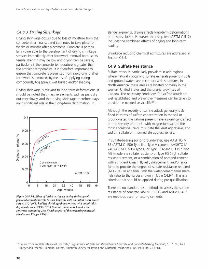
Guide Specification for High-Performance Concrete for Bridges
30
C4.8.3 Drying Shrinkage
Drying shrinkage occurs due to loss of moisture from theconcrete after final set and continues to take place forweeks or months after placement. Concrete is particu-larly vulnerable to the development of drying shrinkagestresses immediately after formwork removal because itstensile strength may be low and drying can be severe,particularly if the concrete temperature is greater thanthe ambient temperature. It is therefore important toensure that concrete is prevented from rapid drying afterformwork is removed, by means of applying curingcompounds, fog sprays, wet burlap and/or shading.
Drying shrinkage is relevant to long-term deformations. Itshould be noted that massive elements such as piers dryout very slowly, and that drying shrinkage therefore playsan insignificant role in their long-term deformation. In
0
0.02
0.04
0.06
0.08
0.1
Dry
ing
shrin
kage
,%
0 8 16 24 32 40 48 56 64Age, weeks
23
°C(73°F)
4°C(40°F)
ASTM C 157
Cement content = 307 kg/m3 (517 lb/yd3)
Figure C4.8.3-1. Effect of initial curing on drying shrinkage ofportland cement concrete prisms. Concrete with an initial 7-day moistcure at 4°C (40°F) had less shrinkage than concrete with an initial 7-day moist cure at 23°C (73°F). Similar results were found withconcretes containing 25% fly ash as part of the cementing material(Gebler and Klieger 1986).
slender elements, drying affects long-term deformationsor prestress losses. However, the creep test (ASTM C 512)includes the combined effects of drying and long-termloading.
Shrinkage reducing chemical admixtures are addressed inSection C5.4.
C4.9 Sulfate ResistanceSulfate attack is particularly prevalent in arid regionswhere naturally occurring sulfate minerals present in soilsand ground waters are in contact with structures. InNorth America, these areas are located primarily in thewestern United States and the prairie provinces ofCanada. The necessary conditions for sulfate attack arewell established and preventive measures can be taken toprovide the needed service life18.
Although the severity of sulfate attack generally is de-fined in terms of sulfate concentration in the soil orgroundwater, the cations present have a significant effecton the severity of attack, with magnesium sulfate themost aggressive, calcium sulfate the least aggressive, andsodium sulfate of intermediate aggressiveness.
In sulfate-bearing soil or groundwater, use AASHTO M85 (ASTM C 150) Type II or Type V cement, AASHTO M240 (ASTM C 595) Type IS or Type IP, ASTM C 1157 TypeMS (moderate sulfate resistant) or Type HS (high sulfateresistant) cement, or a combination of portland cementwith sufficient Class F fly ash, slag cement, and/or silicafume to provide the degree of sulfate resistance required(ACI 201). In addition, limit the water-cementitious mate-rials ratio to the values shown in Table C4.9-1. This is acriterion that should be applied during pre-qualification.
There are no standard test methods to assess the sulfateresistance of concrete. ASTM C 1012 and ASTM C 452are methods used for testing cements.
18 DePuy, “Chemical Resistance of Concrete,” Significance of Tests and Properties of Concrete and Concrete-Making Materials, STP 169C, PaulKlieger and Joseph F. Lamond, Editors, American Society for Testing and Materials, Philadelphia, PA, 1994, pp. 263-281.

31
Guide Specification for High-Performance Concrete for Bridges
Rating:1.0 = no deterioration5.0 = severe deterioration
5.0
4.0
3.0
2.0
1.0
0.3 0.4 0.5 0.6 0.7 0.8
Vis
ualr
atin
g
Water-cement ratio by mass
ASTM Type I,
ASTM Type II,
ASTM Type V,
A
Figure C4.9.2. Average 16-yr ratings of concrete beams in sulfate soilsfor three portland cements at various water-cement ratios (Stark 2002).
Figure C4.9.1. Concrete deterioration due to sulfate attack. (IMG16953)
Sulfateexposure
Sulfate (SO4) insoil, % by mass
Sulfate (SO4) inwater, ppm Cement type*
Maximumw/cm-ratio,by massASTM C 1580 ASTM C 150 ASTM C 595 ASTM C 1157
Negligible Less than 0.10 Less than 150 No special type required —
Moderate(includesseawater)
0.10 to 0.20 150 to 1500 II
IP(MS), IS(MS),P(MS),I(PM)(MS),I(SM)(MS)
MS 0.50
Severe 0.20 to 2.00 1500 to 10,000 V HS 0.45
Very severe Over 2.00 Over 10,000 V HS 0.40
Table C4.9-1. Requirements for Concrete Exposed to Sulfates in Soil or Water
* Pozzolans and slag that have been determined by test or service record to improve sulfate resistance may also be used.
Adapted from ACI 318 (2005).

Guide Specification for High-Performance Concrete for Bridges
32
Slump FlowTest is performed similar to the conventional slump test (ASTMC 143) using the Abrams cone (use of inverted cone possible).However, instead of measuring the slumping distance vertically,the mean spread of the resulting concrete patty is measured hori-zontally. This number is recorded as the slump flow.
Measured characteristic: Filling ability (deformability) &stability.
J-RingThe J-Ring consists of a ring of reinforcing bar such that it will fitaround the base of a standard slump cone. The slump flow withand without J-Ring is measured, and the difference calculated.
Measured characteristic: Passing ability.
Column SegregationTest evaluates static stability of a concrete mixture by quantifying aggregate segregation. A columnis filled with concrete and allowed to sit for awhile after placement. The column is then separatedinto three or four pieces. Each section is removed individually and the concrete from that section iswashed over a No. 4 sieve and the retained aggregate weighed. A non-segregating mix will have aconsistent aggregate mass distribution in each section. A segregating mix will have higher concentra-tions of aggregate in the lower sections.
Measured characteristic: Stability.
Figure C4.10-1. QCQA tests for SCC. (IMG16973, IMG16972, IMG16971)
C4.10 ConsistencyMonitoring consistency is a valuable tool for assessingthe between-batch uniformity of concrete. It may bepreferred to allow the contractors to choose a slump thatis suitable for their equipment, and to impose a limit onvariability between batches. Consistency of normal con-crete is most commonly measured using the slump test.
Self-consolidating concrete (SCC) is not the same asconventional flowing concrete produced using a high-range water-reducing admixture. A number of testmethods are under consideration by ASTM to charac-terize the placement properties of SCC, including the“slump flow” test, “Column Segregation” test, and“J-ring” test19. The slump flow test is conducted using
19 Assaad, J., Khayat, K.H. and Daczko, J., “Evaluation of Static Stability of Self-Consolidating Concrete,” ACI Materials Journal, Vol. 101, IssueNo. 3, May-June 2004, pp. 207-215.

33
Guide Specification for High-Performance Concrete for Bridges
Slump flow
< 22" (550 mm) 22-26" (550-650 mm) > 26" (650 mm)
Reinforcement level
Low
Medium
High
Element shape intricacy
Low
Medium
High
Surface finish importance
Low
Medium
High
Element length
Low
Medium
High
Wall thickness
Low
Medium
High
Placement energy
Low
Medium
High
Mem
ber
char
acte
rist
ics
= Not recommended; potential problem area.
= Recommended
Figure C4.10-2. Slump flow targets. Adapted from Constantiner and Daczko (2002)21.
20 Petersson, Orjan, et. al., Testing SCC, presented at First North American Conference on the Design and Use of Self-Consolidating Concrete,ACBM, Northwestern University, 2002.
21 Constantiner, D. and Daczko, J., “Not All Applications are Created Equal; Selecting the Appropriate SCC Performance Targets,” ConferenceProceedings: First North American Conference on the Design and Use of Self-Consolidating Concrete, November 12-13, 2002.
the slump cone as described in AASHTO T 119 (ASTMC 143); however, rather than measuring the verticalsubsidence or slump, the average diameter of the diskthat spreads out on lifting the inverted cone is mea-sured20. Typical flow values for SCC are in the range of20 to 30 in. (500 to 750 mm).
SCC mixtures usually contain a high-range water-reducingadmixture either alone or in combination with a viscosity-modifying admixture. To achieve desirable placementproperties, SCC mixtures may also incorporate highercementitious materials contents, low water-cementitiousmaterials ratios, and smaller sized aggregates. The aggre-gate grading and moisture content are of particular
importance and must be controlled carefully forconsistent results.
The performance grade for consistency (Table C4.10-1)should be specified as required to produce acceptableconsolidation. In most bridge members, it would be moreappropriate to specify a slump of 3 to 4 in. Grades 2 and3 are self-consolidating concrete, which may be appro-priate for precast members or (for Grade 3) in repairs. Itis recommended that the Engineer not specify a consis-tency performance grade but allow the Contractor topropose it if he desires. The Contractor must demon-strate adequate performance of the concrete as placed inthe trial batches and mockups.

Guide Specification for High-Performance Concrete for Bridges
34
Test
nam
ePu
rpo
seTy
pe
of
test
Cri
teri
aC
om
men
ts
AST
MC
295,
Petr
ogra
phic
exam
inat
ion
ofag
greg
ates
for
conc
rete
Toev
alua
tepo
ssib
leag
gre-
gate
reac
tivity
thro
ugh
petr
ogra
phic
exam
inat
ion
Visu
alan
dm
icro
scop
icex
amin
atio
nof
prep
ared
sam
ples
—sie
vean
alys
is,m
icro
scop
y,sc
ratc
hor
acid
test
s
Agg
rega
teis
pote
ntia
llyre
activ
eif
itsco
nstit
uent
sex
ceed
any
ofth
efo
l-lo
win
g23:•
Opt
ical
lyst
rain
ed,m
icro
-fr
actu
red,
orm
icro
crys
talli
nequ
artz
,5.
0%;•
Che
rtor
chal
cedo
ny,3
.0%
;•
Trid
ymite
orcr
ysto
balit
e,1.
0%•
Opa
l,0.
5%;•
Nat
ural
volc
anic
glas
sin
volc
anic
rock
s,3.
0%
Usu
ally
incl
udes
optic
alm
icro
scop
y.A
lso
may
incl
ude
XRD
anal
ysis
,diff
eren
tial
ther
mal
anal
ysis
,or
infr
ared
spec
tros
copy
—se
eA
STM
C29
4fo
rde
scrip
tive
nom
encl
atur
e
AST
MC
441,
Effe
ctiv
enes
sof
min
eral
adm
ixtu
res
orG
BFS
inpr
even
ting
exce
ssiv
eex
pan-
sion
ofco
ncre
tedu
eto
alka
li-sil
ica
reac
tion
Tode
term
ine
effe
ctiv
enes
sof
supp
lem
enta
ryce
men
ting
mat
eria
lsin
cont
rolli
ngex
pans
ion
from
ASR
Mor
tarb
ars—
usin
gPy
rex
glas
sas
aggr
egat
e—st
ored
over
wat
erat
37.8
°C(1
00°F
)and
high
rela
tive
hum
idity
Per
AST
MC
989,
min
imum
75%
redu
ctio
nin
expa
nsio
nor
0.02
0%m
axim
umex
pans
ion
orpe
rA
STM
C61
8,co
mpa
rison
agai
nst
low
-alk
ali
cont
rol
Not
reco
mm
ende
d.H
ighl
yre
activ
ear
tific
iala
ggre
-ga
tem
ayno
tre
pres
ent
real
aggr
egat
eco
nditi
ons.
Pyre
xco
ntai
nsal
kalie
s.
AST
MC
856,
Petr
ogra
phic
exam
inat
ion
ofha
rden
edco
ncre
te
Toou
tline
petr
ogra
phic
ex-
amin
atio
npr
oced
ures
for
hard
ened
conc
rete
—us
eful
inde
term
inin
gco
nditi
onor
perf
orm
ance
Visu
al(u
nmag
nifie
d)an
dm
icro
scop
icex
amin
atio
nof
prep
ared
sam
ples
See
mea
sure
men
t—th
isex
amin
atio
nde
term
ines
ifA
SRre
actio
nsha
veta
ken
plac
ean
dth
eire
ffec
tsup
onth
eco
ncre
te.U
sed
inco
njun
ctio
nw
ithot
her
test
s.
Spec
imen
sca
nbe
exam
ined
with
ster
eom
icro
scop
es,p
olar
-iz
ing
mic
rosc
opes
,met
allo
-gr
aphi
cm
icro
scop
es,a
ndsc
anni
ngel
ectr
onm
icro
scop
e
AST
MC
1260
(AA
SHTO
T30
3),P
oten
tial
alka
li-re
activ
ityof
aggr
egat
es(m
orta
r-ba
rm
etho
d)
Tote
stth
epo
tent
ialf
orde
lete
rious
alka
li-sil
ica
reac
-tio
nof
aggr
egat
ein
mor
tar
bars
Imm
ersio
nof
mor
tar
bars
inal
kalin
eso
lutio
nat
80°C
(176
°F)
Ifgr
eate
rth
an0.
10%
,go
tosu
pple
-m
enta
ryte
stpr
oced
ures
;if
grea
ter
than
0.20
%,i
ndic
ativ
eof
pote
ntia
lde
lete
rious
expa
nsio
n.
Very
fast
alte
rnat
ive
toC
227.
Use
fulf
orslo
wly
reac
ting
aggr
egat
esor
thos
eth
atpr
oduc
eex
pans
ion
late
inth
ere
actio
n.
AST
MC
1293
,Det
erm
in-
atio
nof
leng
thch
ange
ofco
ncre
tedu
eto
alka
li-sil
ica
reac
tion
(con
cret
epr
ismte
st)
Tode
term
ine
the
pote
ntia
lA
SRex
pans
ion
ofce
men
t-ag
greg
ate
com
bina
tions
Con
cret
epr
isms
stor
edov
erw
ater
at38
°C(1
00.4
°F)
Per
App
endi
xX1
,pot
entia
llyde
lete
ri-ou
slyre
activ
eif
expa
nsio
neq
uals
orex
ceed
s0.
04%
aton
eye
ar
Requ
ires
long
test
dura
tion
for
mea
ning
fulr
esul
ts.U
seas
asu
pple
men
tto
C22
7,C
295,
C28
9,C
1260
,and
C15
67.
Sim
ilar
toC
SAA
23.2
-14A
.
AST
MC
1567
,Pot
entia
lalk
ali-
silic
are
activ
ityof
com
bina
-tio
nsof
cem
entit
ious
mat
eri-
als
and
aggr
egat
e(a
ccel
erat
edm
orta
r-ba
rmet
hod)
Tote
stth
epo
tent
ialf
orde
le-
terio
usal
kali-
silic
are
actio
nof
cem
entit
ious
mat
eria
lsan
dag
greg
ate
com
bina
tions
inm
orta
rba
rs
Imm
ersio
nof
mor
tar
bars
inal
kalin
eso
lutio
nat
80°C
(176
°F)
Ifgr
eate
rth
an0.
10%
,ind
icat
ive
ofpo
tent
iald
elet
erio
usex
pans
ion;
use
C12
93to
conf
irm
Very
fast
alte
rnat
ive
toC
1293
.Use
fulf
orslo
wly
reac
ting
aggr
egat
esor
thos
eth
atpr
oduc
eex
pans
ion
late
inth
ere
actio
n.
Acc
eler
ated
conc
rete
prism
test
(mod
ified
AST
MC
1293
)To
dete
rmin
eth
epo
tent
ial
ASR
expa
nsio
nof
cem
ent-
aggr
egat
eco
mbi
natio
ns
Con
cret
epr
isms
stor
edov
erw
ater
at60
°C(1
40°F
)
Pote
ntia
llyde
lete
rious
lyre
activ
eif
expa
nsio
neq
uals
orex
ceed
s0.
04%
at91
days
Fast
alte
rnat
ive
toC
227.
Goo
dco
rrel
atio
nto
AST
MC
227
for
carb
onat
ean
dse
dim
enta
ryro
cks.
Tabl
eC
4.11
-1.T
estM
etho
dsfo
rA
lkal
i-Si
lica
Rea
ctiv
ity
(ada
pted
from
Farn
yan
dK
osm
atka
1997
22)
22
Farn
y,Ja
mes
A.,
and
Kos
mat
ka,
Stev
enH
.,D
iagn
osis
and
Con
trol
ofA
lkal
i-Agg
rega
teRe
actio
ns,
IS41
3,Po
rtla
ndC
emen
tA
ssoc
iatio
n,19
97,
24pa
ges.
23
Gui
deSp
ecifi
catio
nfo
rC
oncr
ete
Subj
ecte
dto
Alk
ali-S
ilica
Reac
tions
,Po
rtla
ndC
emen
tA
ssoc
iatio
n,IS
415,
Sept
embe
r19
98,
8pa
ges.

35
Guide Specification for High-Performance Concrete for Bridges
Figure C4.11-1. Cracking of concrete from alkali-silica reactivity. (IMG12421,IMG13049)
C4.11 Alkali-Silica ReactivityThere are currently two ASTM test methods that use theactual job materials in combination. In ASTM C 1567, theaggregates are crushed and sieved to a specified gradingand mortar bars made using the proposed dosages ofthe proposed cementitious materials. The mortar bars aresubmerged in a NaOH solution at 100°F (38°C) and theexpansion after 14 days’ exposure is the criterion fordetermining the effectiveness of the control measures. InASTM C 1293, concrete prisms are made from the jobmaterials using the aggregates sieved and recombined tothe specified grading. The specimens are stored overwater in a closed container at 100°F (38°C) for twoyears. While the duration of this test makes it impractical
to use on a job in most cases, materials suppliers or statehighway departments already may have data on theperformance of the proposed job materials. If so, thesedata may be used in preference to data from ASTMC 1260. This is a prequalification criterion.
The basic premise of ASTM C 441 is that low-alkalicement provides adequate control of expansions due toalkali-silica reaction. This is not true of all aggregates.Thus, the test may be used to compare the relative effec-tiveness of different combinations of cementitious mate-rials, but not to evaluate the acceptability of a givencombination of cementitious materials. ASTM C 1567 isthe recommended test method for that purpose.

Guide Specification for High-Performance Concrete for Bridges
36
C5.0 Materials
C5.1 Cementitious MaterialsCementitious materials when used in combinationsshould be evaluated to determine their effect on thoseconcrete properties which the Engineer has determinedto be significant for the project, including water demand, setting time, heat development, strength development,shrinkage characteristics, and early stiffening24.
24 Kosmatka, Steven H.; Kerkhoff, Beatrix; and Panarese, William C., Design and Control of Concrete Mixtures, EB001, Portland CementAssociation, 2002, 372 pages.
25 Shilstone, James M. Sr. and Shilstone, James M. Jr., “Performance-Based Concrete Mixtures and Specifications for Today,” ConcreteInternational, Vol. 24, No. 2, February 2002, pp. 80-83.
Figure C5.1-1. Supplementary cementitious materials. From left toright, fly ash (Class C), metakaolin (calcined clay), silica fume, fly ash(Class F), slag, and calcined shale. (IMG16974)
C5.2 Aggregates
C5.2.1 Grading and Impurities
Proper grading of the aggregates is key to good worka-bility, low water demand, and efficient filling of thevolume. Efficient filling of the volume by aggregates(with the consequent minimization of paste volume) isimportant for maximizing stiffness (modulus of elasticity),minimizing creep and shrinkage, and minimizing thegeneration of heat of hydration.
Particle size grading, together with the particle shape,determines the packing characteristics of the aggregate,that is, its ability to fill space. Any space not filled withaggregate must be filled with cement paste, which istypically more expensive than aggregate and is prone toshrinkage and thermal cracking. The most efficientpacking is obtained with rounded, equidimensional parti-cles of uniform grading. Sieve analyses for both coarseand fine aggregates should be performed according toAASHTO T 27 (ASTM C 136). The aggregate should meetthe requirements of AASHTO M 6 and M 80 (ASTMC 33) except as noted.
Figure C5.2.1-1 provides a guide for the grading of thecombined coarse and fine aggregates. Zone I mixturestend to segregate during placement. Zone II representsthe desirable range with the position of the dot and thesurrounding region bounded by the parallelogram beingthe optimum. Zone III is an extension of Zone II of aggre-gates 0.5 in. (13 mm) and finer. Zone IV concrete wouldhave too much fine mortar. Zone V concrete would betoo rocky25.
Clays and silts can increase water demand in fresh con-crete, increase drying shrinkage, impair paste-to-aggre-gate bond, and cause disruptive swelling within thehardened concrete. Organic impurities can adverselyaffect setting times and strengths.
The grading of the fine aggregate fraction is also impor-tant for an additional reason: Too little fines make theconcrete difficult to extrude and finish as well as moreprone to bleeding, too much increases the water demandof the concrete and the required dosage of air-entrainingadmixture. For slip form paving, the minimum limit forthe fineness modulus (calculated according to AASHTOT 27 (ASTM C 136) is 2.3. The fine aggregate shouldhave no more than 45% passing any one sieve andretained on the next consecutive sieve.

37
Guide Specification for High-Performance Concrete for Bridges
C5.2.2 Durability
C5.2.2.1 Alkali-Silica Reactivity
These guidelines are adapted from PCA IS415.
The tests for aggregate reactivity may be performed inany order. In general, ASTM C 1260 is considered conser-vative in that it may identify seemingly innocuous aggre-gates as reactive. ASTM C 1293 is considered moredefinitive but takes a full year to identify aggregates asreactive and two years to verify the effectiveness of miti-gation measures. ASTM C 441 is not recommendedbecause it does not represent the actual aggregate to beused and because the underlying assumption that low-alkali cement produces an acceptable result with allaggregates is not valid.
When requesting an evaluation of the aggregate byASTM C 295, it is helpful to provide the petrographer
with the list of reactive constituents and their allowablelimits.
In developing a quarry, aggregate producers may haveobtained ASTM C 1293 data for their aggregate withcombinations of local cementitious materials. Such datawould be acceptable in specifying concrete for a partic-ular job. Some slowly reactive aggregates produce a“borderline” expansion value according to ASTM C 1293.In this situation it is helpful to plot the expansion versustime. If the slope of this line at the end of the test periodindicates that the expansion is not leveling off, it is pru-dent to specify some mitigation measure. In the absenceof these data or sufficient time to develop them, theprudent course would be to rely on ASTM C 1260 toidentify the aggregate as reactive and ASTM C 1567 toselect an appropriate mitigation measure. A range ofcombinations of cementitious materials could be testedsimultaneously and all acceptable combinations includedin the job specification.
TREND BAR
IV
II
V
I
III
100 80 60 40 20 0
Coarseness factor, combined aggregatesPercent retained on No. 8 sieve that is also retained on 3/8" sieve
Wor
kabi
lity
fact
or,c
ombi
ned
aggr
egat
esP
erce
ntpa
ssin
gN
o.8
siev
ead
just
edfo
rce
men
titio
usco
nten
t
45
40
35
30
25
Figure C5.2.1-1. A satisfactory aggregate grading falls within Zone II on this plot.22

Guide Specification for High-Performance Concrete for Bridges
38
Mitigation measures include the use of pozzolans and/orslag cement, either as a component of blended cementor as a separate addition at the concrete productionfacility. In some cases, the quantity of supplementarycementitious material in blended hydraulic cement is notsufficient to control expansions due to alkali-silica reac-tion. Additional supplementary cementitious material,either of the same or different kind, may be added to theblended hydraulic cement if necessary. As a guideline,Class F fly ash may require 15% to 25% by mass of totalcementitious materials to meet the expansion criterion,while slag cement may require 40% to 50% and calcinedclay approximately 15% to 20%. Class C fly ash is notgenerally recommended for this purpose, as it may actu-ally increase expansions at some dosages. Ternary combi-nations (using two supplementary cementitious materials)also can be very effective.
It is essential to avoid making substitutions of one mate-rial for another on the job without testing. Fly ashesmeeting the requirements of AASHTO M 295 (ASTMC 618) for Class F fly ash may be considerably differentwith regard to their effectiveness in controlling expan-sions due to alkali-silica reaction because of their con-tents of lime and/or alkalis, or because of their reactivity(a function of particle size and composition). Likewise,cements meeting the requirements of AASHTO M 85(ASTM C 150) for Type I cement may require differentdosages of the same fly ash to produce acceptable resultswith the same aggregate. If supplies are uncertain and itis anticipated that substitutions may have to be madeduring the course of the job, combinations of variouspossible job materials can be tested simultaneously todetermine which ones produce acceptable results. Thenall acceptable combinations may be listed in the specifi-cation and the final selection left to the Contractor orconcrete producer.
In scattered areas of the Northern Great Plains, theglacial sands containing shale particles can be susceptibleto popouts caused by alkali-silica reaction. Found moston hard-troweled surfaces, these popouts are muchsmaller and shallower than those caused by absorptivecoarse aggregates. The popouts are very unusual in thatthey often appear a few hours after the concrete isfinished and, in most cases, within the first few weeks.
The following procedures offered the best protectionagainst the formation of popouts when reactive sandsare used26.
1. In the hot summer months, wet curing is essential.Wet curing should be initiated as early as possible.
2. Fresh concrete should be protected from dryingbefore final finishing.
3. Hard-troweling should be avoided, if possible.
C5.2.2.2 Alkali-Carbonate Reactivity
Alkali-carbonate reactive aggregates are problematic onlyin limited geographical areas. The most conservativepractice is to avoid the use of reactive aggregates byselective quarrying. Reactive aggregates may beidentified by testing in accordance with ASTM C 1105.
26 Landgren, R., and Hadley, D. W., Surface Popouts Caused by Alkali-Aggregate Reaction, RD121, Portland Cement Association, 2002.
Figure C5.2.2.2-1 Micrograph showing cracks due to alkali carbonatereaction (ACR) caused by argillaceous (clay-rich) dolomitic limestoneaggregates. (IMG16952)
C5.2.2.3 D-Cracking
D-cracking may be a concern for concrete subjected tofreezing and thawing under conditions of saturation. Itmay be of relevance for some bridge decks, but not forother bridge elements. Generally, the larger the particlesize, the more susceptible the aggregate is to D-cracking.Aggregate susceptible to D-cracking must be either

rejected or beneficiated so that the particles of suscep-tible size are removed. The resulting reduction in themaximum size of the aggregate requires a concomitantchange in the concrete mix design so that the proportionof aggregate is reduced and the proportion of cementi-tious material is increased. This may increase the cost ofthe concrete. More important, the increased pastecontent results in greater vulnerability to cracking due toincreased thermal stresses and autogenous, plastic, anddrying shrinkage. If there is an aggregate available that isnot susceptible to D-cracking, it is prudent to use it.
39
Guide Specification for High-Performance Concrete for Bridges
Figure C5.2.2.3-1. D-cracking along a transverse joint caused by failure of carbonate coarse aggregate. (IMG12314, IMG12315)
Nearly all rock types susceptible to D-cracking are of sedi-mentary origin. If the performance history of a proposedaggregate is unknown and the concrete will be subjectedto freezing, the aggregate must be tested. The Washing-ton Hydraulic Fracture test27 is the most direct method. Itrequires a special apparatus in which surface-sealedaggregate is placed in water. The vessel is subjected to10 cycles of pressurization. The aggregate particles arecounted to determine an index of susceptibility to D-cracking. AASHTO T 161 (ASTM C 666) tests the dura-bility of concrete under cycles of freezing and thawing inconditions likely to saturate the concrete. Modificationsfor the purpose of testing aggregate for susceptibility toD-cracking include increasing the number of cycles to350 and calculating the durability index from the expan-sion of the specimens. In the Iowa Pore Index Test28,29
the aggregate is sealed into the pot of an AASHTO T 152(ASTM C 231) air meter. Water is added to a certain levelin the transparent tube at the top of the pot. Air pressureis applied to force the water into the pores of the aggre-gate. The decrease in the volume is called the pore index.A high pore index indicates a nondurable aggregate.
27 Janssen, Donald J. and Snyder, Mark B., Resistance of Concrete to Freezing and Thawing, SHRP-C-391, Washington, DC: Strategic HighwayResearch Program, National Research Council, 1994, 301 pp.
28 Traylor, M.L., “Efforts to Eliminate D-Cracking in Illinois,” Transportation Research Record, No. 853, 1982, pp. 9-14.29 Marks, V.J. and Dubberke, W., “Durability of Concrete and the Iowa Pore Index Test,” Transportation Research Record, No. 853, 1982, pp.
25-31.

Guide Specification for High-Performance Concrete for Bridges
40
C5.3 WaterRefer to PCA EB001, Design and Control of ConcreteMixtures, for a complete discussion of water for use inconcrete. In general, water suitable for drinking and withno perceptible taste or odor is suitable for makingconcrete. Some non-potable waters including recycledwash waters, are also acceptable for use in concrete butmust be tested to verify that no harmful effects will
Figure C5.3-1. Water that is safe to drink is safe to use in concrete.(IMG12312)
result. AASHTO M 157 (ASTM C 1602) also providesguidance on the acceptability and testing of water foruse in concrete.
C5.4 Chemical AdmixturesIt is advisable to purchase all of the chemical admixturesto be used in the concrete from a single manufacturer.Certain chemical admixtures are incompatible with oneanother, or with certain cementitious materials.Generally, manufacturers test their own admixtures incombinations with one another using the availablecementitious materials and can advise the user of poten-tial interactions.
Early stiffening may result when water-reducingadmixtures containing lignosulfonate and/ortriethanolamine (TEA) are used in combination with somecements and Class C fly ashes, particularly in hotweather. Trial batches should be conducted at workingtemperatures to assess the likelihood of incompatibility.Tests conducted on the trial batches should include moni-toring slump loss, time of set, and the temperature ofthe mixture with time.
ACI 201.2 reports that if chloride ions in an admixtureare less than 0.01% by mass of cementitious material,such contribution represents an insignificant amount andmay be considered innocuous.
Figure C5.3-2. Microwave Water Content Test (AASHTO T 318). Freshly mixed concrete wrapped in a fiberglass cloth in a heat-resistant glass tray(Pyrex) is dried in a microwave oven using a minimum of three drying intervals. The water content of the test specimen is calculated based on loss inmass of the test specimen. The w/c ratio can then be determined by dividing the amount of water from the microwave tests by the amount of cementindicated on the batch ticket. (left: IMG17613, right: IMG17614).

41
The surface tension of the water in partially filled pores inconcrete pulls inward on the walls of the pores, resultingin shrinkage of the concrete. Shrinkage-reducing admix-tures reduce the surface tension of the pore water,reducing both the shrinkage and the susceptibility tocracking under restrained conditions. Shrinkage-reducingadmixtures are used conventionally in applications wherea notable reduction in drying shrinkage is desired andalso may benefit concrete mixtures susceptible to autoge-nous shrinkage30. Shrinkage-reducing admixtures mayaffect strength, resistance to chloride ion ingress, freeze/thaw durability, modulus of elasticity, creep, and long-term shrinkage. They should never be used in lieu ofproper curing.
Hydration-stabilizing admixtures may be useful in situa-tions where a controlled extension of set time is desired,such as extended hauls and during large continuousplacements. Unlike conventional set retarding admix-tures, hydration-stabilizing admixtures are formulated toprovide extended set time control. Depending on thedosage used, set time extensions can range from a fewhours to over a day.
Corrosion inhibiting admixtures may be added to concreteto reduce the risk of corrosion of steel embedded inconcrete. These products must be used in conjunction withand not in lieu of good concrete materials and practice.
Guide Specification for High-Performance Concrete for Bridges
Figure C5.4-1. Liquid admixtures, from left to right: antiwashoutadmixture, shrinkage reducer, water reducer, foaming agent, corrosioninhibitor, and air-entraining admixture. (IMG12188)
Figure C6.1-1. Testing concrete mixes in the lab is often moreconvenient and economical than having to batch large quantities at aconcrete plant. It is important to recognize that project conditions arevastly different than the controlled environment of a laboratory.Production variability and testing variability need to be consideredand understood when lab tests results are interpreted. (IMG16954)
C6.0 Submission and DesignRequirements
C6.1 Concrete Mixture ProportioningIn times of high demand for concrete-making materials,it is recommended that alternate mix designs using alter-nate materials be submitted for approval simultaneously.If a material then becomes unavailable during the courseof a job, the concrete producer may substitute anothermaterial and the appropriate mix design without delay.The concrete producer must inform the purchaser whensubstitutions are to be made, even when the materialsand mix designs already have been approved.
For mixture proportioning, refer to “Design and Con-trol31,” or ACI 211.1 for normal density concrete,ACI 211.2 for lightweight concrete, and ACI 211.4 forhigh-strength concrete containing fly ash. Recommen-dations for proportioning high-strength concrete also arecovered in Chapter 3 of ACI 363R.
30 Tazawa, Ei-ichi, Ed., “Autogenous Shrinkage of Concrete,” Proceedings of the International Workshop Organized by the Japan ConcreteInstitute, E&FN Spon, 1999, p. 14.
31 Kosmatka, Steven H.; Kerkhoff, Beatrix; and Panarese, William C., Design and Control of Concrete Mixtures, EB001, Portland CementAssociation, 2002, 372 pages.

Guide Specification for High-Performance Concrete for Bridges
42
Note that the end product of the ACI mix proportioningmethods is not a prescriptive “recipe” for a concrete mixdesign, but a starting point for laboratory trial batches.Such characteristics as the packing efficiency and waterdemand of the aggregates will affect the actual quantityof cement paste required for the desired workability. Thedosages of water reducing and air-entraining admixturesalso must be determined by trial batches using themanufacturer’s recommended dosages as the startingpoint. In addition, all properties of the fresh andhardened concrete determined by the Engineer to beimportant to the project must be tested to ensure thatthe mix design meets the project requirements.
C6.2 Concrete Production FacilityCertificationThe NRMCA truck and plant certification programsfollow a checklist inspection process for components andsystems in concrete plants and verify that they conformto the requirements of AASHTO M 157 (ASTM C 94) andpertinent standards of concrete production equipment.
C6.3 Concrete MaterialsWhen producing high-performance concrete, it is advis-able for the concrete producer to retain traceable grabsamples of the constituent concrete-making materialsfrom each day’s production. The retained samples allowfor later investigation of any problems with the concrete.A 5-gallon (20 liter) pail of each aggregateand cementitious material, representative ofeach day’s production with that ingredient,is sufficient for this purpose. Samplesshould be retained for six months.
C6.4 Temperature ControlMethodsRecommended practices for controlling theplacement temperature and in-placetemperature of concrete placed during hotweather and cold weather are detailed inACI 305R and 306R, respectively, and in PCIMNL-116 and TM-103.
C6.5 Crack Control MethodsCracks may be caused by any combinationof stresses arising from restraint of autoge-nous, plastic, or drying shrinkage; thermalgradients; imposed loads; and stressconcentrations such that the tensile stressexceeds the tensile strength of the concrete.
The Engineer and Contractor should work together toselect the combination of crack control measures thatbest meets the requirements of the project at areasonable cost.
Crack control measures related to the selection ofconstituent ingredients and proportioning of the concretemixture include:
1. Selection of a suitable cement.
2. Replacement of some of the cement with a low-calcium (Class F) fly ash, or use a blended cementcontaining Class F fly ash.
3. Minimization of the water content. This may be doneby employing a water reducer and/or by selecting afavorable aggregate size and grading. The use of acompatible fly ash also may reduce water demand.
4. Selection of an aggregate with a low coefficient ofthermal expansion and a rough surface texture.Maximize the aggregate content by specifying thelargest possible maximum size and a favorableparticle size grading.
5. Use of a shrinkage-reducing admixture, possibly incombination with carbon or steel fibers.
I
H
H
H
G
I
D
C
K
IB
AA
J
E
F
B
B
L
M
Cracks atkicker joints
Shearcracks
“Bad,” i.e. ineffective, joint Tensionbendingcracks
Plus ruststains
Top of kicker
Figure C6.5-1. An illustration of nonstructural cracks that may occur in a hypotheticalconcrete structure (Concrete Society, 1982).A to C—plastic settlement, D to F—plastic shrinkage, G to H—thermal effects, I—dryingshrinkage, J to K—crazing, L to M—reinforcement corrosion, N—alkali silica reaction.

43
6. Reducing the modulus of elasticity (stiffness) by theentrainment of 4% to 6% air in the concrete even ifit is not necessary for frost resistance.
7. Use of an aggregate with an absorption of less than1%, or ensuring that the aggregate moisturecondition is always at or above saturated surface dry.
Crack control measures related to workmanship include:
1. Control of the placement temperature. The concreteshould not be much cooler than the ambient temper-ature, however. In winter, it may be advantageous forthe concrete to be somewhat warmer than theambient temperature. Depending on the importanceof controlling cracking, a detailed analysis of thermalstresses may be necessary.
2. Use of established procedures for hot-weather andcold-weather concreting to control concrete quality.
3. Appropriate construction management to have suffi-cient personnel at the site to place, consolidate, andfinish the concrete promptly.
4. Provision of fog sprays and windbreaks as necessaryto prevent the surface of the concrete from drying.
5. Curing the concrete as soon as possible.
6. Control of the temperature after placement. Allowingcontrolled evaporation of water from absorptive blan-kets on the surface is an effective means of bothcooling and moist curing.
7. Adherence to established procedures for good con-creting practice. Consult the documents of AmericanConcrete Institute Committees 201, 207, 224, 232,233, 234, 304, 305, 306, 308, 309, 345, and/or 363,and PCI MNL–116 as appropriate.
Crack control measures related to structural design anddetailing include:
Guide Specification for High-Performance Concrete for Bridges
1. Minimization of strains likely to occur in structuralelements. For example, to minimize cracking in abridge deck it may be necessary to limit the deflectionof the supporting girders.
2. Limiting the maximum dimensions of any structuralelement by providing construction joints.
3. Not specifying a higher strength than necessary, or ifpossible, specifying a 56- or 90-day strength ratherthan an earlier age strength.
4. Minimization of the restraint to which the concrete issubjected.
5. Use of reinforcing steel to develop a greater numberof small cracks rather than a few large cracks.
6. Use of a large number of small-diameter reinforcingbars at close spacing rather than a few large-diameterbars. (Note that the bar spacing must permit ade-quate consolidation of the concrete.)
In evaluating the literature on the relationship betweencorrosion of uncoated reinforcement and cracks perpen-dicular to it, Oesterle32 concluded that for crack widthsless than 0.016 in. (0.4 mm), crack width was of minorimportance. The quality of the concrete and the depth ofcover over the reinforcement are the primary factorsdetermining the service life of cracked concrete. Herecommended limiting crack widths to a maximum of0.016 in. (0.4 mm) for corrosion protection.
Mailvaganam et. al.33 recommended the following limits:
• Maximum of 0.004 in. (0.1 mm) for the most severeexposure (industrial or marine environment wherewatertightness is essential)
• Maximum of 0.008 in. (0.2 mm) for normal exteriorexposures or interior exposures of structural membersin humid or aggressive atmosphere
• Maximum of 0.012 in. (0.3 mm) for internal and pro-tected members
32 Oesterle, R.G., The Role of Concrete Cover in Crack Control Criteria and Corrosion Protection, Portland Cement Association R.& D. Serial No.2054, 1997.
33 Mailvaganam, Noel P.; Grattan-Bellew, P.E.; and Perinca, Gerry, “Deterioration of Concrete: Symptoms, Causes, and Investigation,” NationalResearch Council, Canada, Institute for Research in Construction, Ottawa, Canada, 2000.

Guide Specification for High-Performance Concrete for Bridges
44
C6.6 CuringCuring methods, materials and monitoring proceduresare detailed in ACI 308R and in FHWA FP-03 for cast-in-place concrete and PCI MNL-116 for precast concrete.Where it is practical, moist curing is preferable to theapplication of a curing compound. For precast concrete,use curing described in PCI MNL-116.
The objective of curing is to maintain moisture and tem-perature conditions for sufficient time to allow for thehydration of cementitious materials and pozzolans. Goodcuring is essential for the concrete to develop the desireddurability and strength, and to minimize cracking. De-pending on the properties desired, HPC may have lowerwater-cementitious materials ratio, higher cementitious
Figure C6.6-1. Curing methods that maintain the presence of mixing water in the concrete during the early hardening period includeponding or immersion, spraying or fogging (top left photo), and saturated wet coverings (top right photo). Methods that reduce the lossof mixing water from the surface of the concrete include covering the concrete with impervious paper or plastic sheets, or by applyingmembrane-forming curing compounds (bottom photos). Curing often involves a series of different procedures used at a particular timeas the concrete ages. For example, fog spraying or plastic covered wet burlap can precede application of a curing compound. (IMG16978,IMG16979, IMG16981, IMG16980)

45
materials content, and/or reduced bleeding as comparedwith conventional concretes. The higher the cementcontent, the greater attention should be given to curingmethods to control the development of internal tempera-ture differentials which could lead to cracking. In thecase of aggressively evaporative environments, i.e. lowhumidity and/or windy conditions, use of fogging, sun-shades, windscreens, or enclosures may be necessary toprevent excessive surface drying. Curing must be initiatedbefore the concrete starts to dry.
If water curing is employed, it should be done on a con-tinuous basis throughout the specified curing period.Intermittent water curing that allows concrete to under-go cycles of wetting and drying can be more detrimentalthan no curing at all.
If steam curing is employed, care should be taken to pre-vent the concrete temperature exceeding the tempera-ture above which the risk of delayed ettringite formationmay occur in mixtures containing materials prone to theproblem. In general, 158°F (70°C) is accepted as areasonable upper limit. Higher temperatures may be ac-ceptable for certain materials if proven by field perfor-mance or test.
Both maturity and temperature-matched curing are excel-lent methods of assessing the development of strengthor other properties of the concrete at early ages. Deci-sions such as when to re–move forms, releaseprestressing, or post-tension can be made more reliablywith information from either of these methods. Bothmethods require the use of thermocouples to measurethe temperature history of the concrete.
The maturity method predicts the in-situ strength (orother properties) of the concrete at any time based ondata developed from the trial batches. Thus it requires aninvestment in testing the development of the desiredproperties using trial batches subjected to a range ofcuring conditions representing those anticipated on site.ASTM C 1074 generates a maturity index based on thetemperature history.
The maturity method normally is used to assess the cur-rent strength of the concrete; however, it also can beused to model different hypothetical situations, such asthe length of time formwork should remain in place orwhether it would be effective to use insulated forms orheated enclosures during cool weather to accelerate theconstruction schedule.
Guide Specification for High-Performance Concrete for Bridges
Temperature-matched curing uses data from the thermo-couples to control the curing temperature of companioncylinders. The compressive strength (or other property) ofthe cylinders is determined directly and closely matchesthat of the concrete in the structure at the same time.Temperature-matched curing is thus simpler to imple-ment than the maturity method and provides more directinformation about the current properties of the in-situconcrete, but does not predict properties.
C7.0 Quality ManagementThe guide specification has been based on the presump-tion that a given concrete mixture will be pre-qualified byspecification and testing appropriate for the given ele-ment and environment. Quality assurance and control arethen based on confirming that every load of concreteused at the site is comparable to the pre-qualified mix-ture. This means that it is not necessarily required to testevery property of every load, but to confirm that thematerials and mix proportions are the same as those inthe pre-qualified mix, and that selected indicators of vari-ability (such as air content and consistency) remain withinsuitable bounds.
C7.1 Quality AssuranceRefer to ACI 121R, PCI MNL-116, AASHTO Guide toQuality Control/Quality Assurance, and NRMCA Publi-cation 190 for more detail on quality assurance systems.
C7.2 Quality ControlRecommended practices related to quality control andtesting of high-strength concrete are detailed in ACI363.2, “Guide to Quality Control and Testing of High-Strength Concrete,” PCI MNL-116, NRMCA QualityControl Manual, and NRMCA Publication 190.
In principle, sufficient testing is required to ensure thatthe requirements of the specification are being compliedwith, and that a uniform product is being produced. Thetests should be related to the parameters deemed impor-tant in the specification. Some tests may be conducted atpre-qualification stage to assure that the mix designprovides an adequate concrete, while production accep-tance testing may be done to demonstrate that the con-crete being delivered from batch to batch is equivalent tothe qualified mixture.

Guide Specification for High-Performance Concrete for Bridges
46
C8.0 Production of Concrete
C8.1 General
C8.2 EquipmentIn situations where discharge of the concrete may not becompleted within the allowable time limitations, such asextended hauls, hydration-stabilizing admixtures may bebeneficial. Hydration-stabilizing admixtures are discussedin Section C5.4.
C8.3 Measurement of MaterialsConsult the admixture manufacturer’s literature for guid-ance as to the order in which admixtures should beadded to the concrete, as this will affect their perfor-mance. In general, admixtures should be introducedseparately to the batch.
Materials quantities in freshly mixed or hardened con-crete can be approximated using a number of tech-niques. The water content of fresh concrete can bedetermined using the Microwave test (AASHTO T 318,)except that allowance has to be made for the moisturestate of the aggregate at the time of mixing. Cementcontent may be estimated using ASTM C 1084 forsystems that do not contain supplementary cementitiousmaterials. Monitoring unit weight will provide a means offlagging changes in mixture proportions.
C8.4 MixingIt is essential to ensure thorough mixing, both for uni-form distribution of the concrete ingredients throughoutthe batch and to entrain an adequate air-void system.However, overmixing may remove entrained air from theconcrete. In addition, with some synthetic air-entrainingadmixtures, retempering and extended mixing can resultin excessive air and/or clustering of air voids. Trial batchesand mockups should be used to verify that the ingre-dients and procedures used would result in satisfactoryair-void systems in the concrete as placed.
If silica fume is used, particular attention must be paid tothe batching sequence and mixing procedure to ensureuniform mixing. The use of a blended cement containing
silica fume guarantees uniform mixing. The use of pulp-able bags of silica fume is not advisable, as it may bedifficult to achieve adequate mixing. The specifier maywish to consult the silica fume supplier for recom-mendations.
C8.5 Temperature ControlTemperature of concrete is important for the developmentof properties related to strength and durability. So long asthe concrete is protected from freezing, low temperaturesresult in the development of favorable properties, but at asignificantly slower rate. Early-age freezing of concretemay disrupt the paste microstructure and permanentlydamage the concrete. Elevated temperatures result inaccelerated setting and high early strengths but reducedultimate strengths, as well as higher permeability andgreater potential for delayed ettringite formation. Theexact temperature at which the concrete becomes vul-nerable to delayed ettringite formation varies with thecementitious material(s) employed.
In general, 158°F (70°C) is accepted as a reasonableupper limit. Higher temperatures may be acceptable forcertain materials if proven by field performance or test.The maximum temperature of 158°F (70°C) is specifiedfor two reasons:
1. Delayed ettringite formation is possible under somecircumstances when the temperature exceeds thisvalue.
2. The higher the curing temperature, the more perme-able the concrete.
Appropriate use of supplementary cementitious materialswill reduce or eliminate the possibility of delayedettringite formation34.
Some concrete ingredients and mix proportions arebetter suited than others for extreme weather conditions.In hot weather, supplementary cementitious materialssuch as Class F fly ash and slag cement, which generateless heat of hydration than cement, help keep the heatdevelopment of the concrete in the appropriate range,thus minimizing the likelihood of thermal cracking. Theyalso can make the concrete less susceptible to prematurestiffening.
34 Miller, F.M., and Conway, T., “Use of Ground Granulated Blast Furnace Slag for Reduction of Expansion Due to Delayed Ettringite Formation,”Cement, Concrete and Aggregates, Vol. 25, Issue. 2, 2003, pp. 59-68.

47
C8.5.1 Cold Weather
The primary concerns relating to cold weather are slowsetting and slow strength gain, permanent damage tothe concrete due to early freezing, and excessive thermalgradients that may lead to cracking.
When concrete is to be placed in cold weather, or at atime of year when cold weather is likely, plans to main-tain the concrete at the appropriate temperature shouldbe made well before the temperature is expected to dropbelow freezing.
Concrete mix designs developed for placement at coolertemperatures normally have somewhat higher cementcontents than those for hot weather. The use of slagcement and fly ash may need to be reduced or elimi-nated unless they are required to control expansions dueto alkali-silica reaction or to increase the resistance tosulfate attack or to reduce permeability. In that case, thetotal cementitious materials content may need to beincreased, or Type III or Type HE cement may be usedinstead of Type I/II. The required dosage of air-entrainingadmixture will be lower than at normal temperatures.The longer setting time of concrete in cold weatherincreases the window of vulnerability to plastic shrinkagecracking. If the concrete is much warmer than theambient air or the wind is blowing, the local reduction inrelative humidity also can contribute to plastic shrinkagecracking. Concrete surfaces must be protected fromdrying with windbreaks, application of curing compound,etc. An accelerating admixture conforming to AASHTO M194 (ASTM C 494) Type C or E may be used provided itsperformance previously has been verified by trial batch.
Use of admixtures containing chlorides is not recom-mended and in prestressed or post-tensioned concrete isstrictly prohibited.
Ideally, concrete should not be placed when the tempera-tures of the air at the site or the surfaces on which theconcrete is to be placed are less than 40°F (5°C). Ifcircumstances require that concrete be placed at thesetemperatures, special provisions are required as detailedin ACI 306R and PCI MNL-116. Covering and/or othermeans of protecting the concrete should be available onsite before starting placement. The concrete temperatureshould be maintained at 50°F (10°C) or above for at least72 hours after placement and at a temperature above
Guide Specification for High-Performance Concrete for Bridges
Figure C8.5.1-1. Concrete being covered with a tarpaulin to retain heatof hydration. (IMG15215)
freezing for the remainder of the curing period. If theconcrete is to be heated, it should be by a method thatdoes not expose the concrete to CO2 gas. Note thatcorners and edges are the most vulnerable to freezing.Concrete damaged by pre-mature freezing must becompletely removed and replaced.
Note that in colder temperatures, concrete gains strengthmore slowly. This effect is more pronounced for concretecontaining supplementary cementitious materials. Beforeremoving formwork or post-tensioning structural ele-ments, the adequacy of the in-place compressivestrength of the concrete must be verified by the maturitymethod, temperature-matched curing, nondestructivetesting, or tests of cores.
Guidance and further details on cold weather concretingpractices are given in ACI 306R and PCI MNL-116.
C8.5.2 Hot Weather
The primary concerns relating to hot-weather concretinginclude increased water demand, premature stiffening,loss of workability, increased rate of setting, loss ofentrained air, plastic shrinkage cracking, decreased later-age strength, excessive hydration temperatures, andexcessive thermal gradients leading to cracking. Highperformance concrete may experience little or nobleeding; thus it is particularly sensitive to plasticshrinkage cracking.

The concrete mix design used for hot weather shouldhave been previously verified as appropriate using trialbatches mixed and cast at temperatures representative oftypical hot weather conditions at the site. The use of slagcement, Class F fly ash, and/or natural pozzolans in substi-tution for part of the cement is recommended. All ofthese materials hydrate more slowly and generate lowerheats of hydration than cement, thus reducing problemswith slump loss, premature stiffening, and thermal crack-ing. Class C fly ashes with high contents of Al2O3 maycontribute to premature stiffening.
Reductions in air contents due to hot weather can becorrected by increasing the dosage of air-entrainingadmixture and/or by retempering with water-reducingadmixture or water to restore the slump. Do not exceedthe maximum allowable water-cementitious materialsratio or manufacturer’s maximum recommended dosagefor any of the admixtures.
Retarding admixtures may be used if their performancepreviously has been verified by trial batches.
Thermal cracking may be prevented by ensuring that thetemperature of concrete at the time of placement is aslow as practical, and in no case should it exceed 90°F(32°C) except in precast concrete plants that havedemonstrated successful use of a maximum temperatureof 95°F (35°C). When possible, store aggregates out ofdirect sunlight. Aggregates also may be cooled and
Guide Specification for High-Performance Concrete for Bridges
48
Calcium sulfate in the form of gypsum and anhydrite isadded to cement to control the hydration of aluminates,preventing early stiffening. Elevated temperatures accel-erate the dissolution of the aluminates and retard thedissolution of the sulfates. Class C fly ashes with highalumina contents can be problematic in hot weather ifthey contribute more aluminates than soluble sulfates tothe concrete. The use of some water-reducing admixturesalso can contribute to early stiffening. This effect is morepronounced in hot weather because of the increasedwater demand of the concrete (thus the tendency to usehigher dosages of water-reducing admixture).
Figure C8.5.2-1. Liquid nitrogen added directly into a truck mixer toreduce the concrete temperature. (IMG12357)
Figure C8.5.2-2. Mass concrete footing where the insulation was removed much too soonand a large thermal gradient developed through the concrete by thermally shocking thesurface. The footing was approximately 5 ft (1.5 m) thick, and the insulation was removedafter ~2 days. The concrete cracked shortly thereafter. (left: IMG17801, right: IMG17802)

49
Guide Specification for High-Performance Concrete for Bridges
moistened by sprinkling with water. If possible, avoid theuse of hot cement or fly ash. Mixing water may bechilled, or chipped ice (batched by mass) may be used insubstitution for some of the water. Be sure that all of theice melts during mixing. Mixing and transporting equip-ment may be painted white or a light color to minimizethe heat absorbed from the sun. Depending on the heatcharacteristics of the concrete, placements may be sched-uled for late afternoon or nighttime to reduce thermalgradients. Delays in placement should be avoided. Theuse of a white curing compound will help reflect thesun’s heat.
Plastic shrinkage cracking results from loss of moisturefrom concrete before it has set. Aggregates should bebatched as close to a saturated condition as possible toavoid absorbing mix water. The concrete should beprotected from loss of moisture during mixing and place-ment. Protection measures may include fog spraying andshelter from wind. Absorbent forms should be dampenedbefore placement. The concrete should be placed andfinished as rapidly as possible and curing compound (ifused) applied as soon as possible. If there is any delay inapplying the curing compound, use a fog spray to keepthe surface from drying out. When the rate of evap-oration is predicted from Figure C8.5.2-3 to be above0.1 lb/ft2/hr (0.5 kg/m2/hr), provide wind screens andfog spraying as appropriate or stop placing concrete.Note that high performance concrete is particularlyvulnerable to plastic shrinkage cracking because it haslittle or no bleeding. Take extra precautions to preventevaporation when placing silica fume concrete in hotweather. If plastic shrinkage cracking is observed, theContractor should provide wind screens and more fogspraying as needed. If these measures are not effective,operations should stop until weather conditions improve.35
Guidance and further details on hot-weather concretingpractices are given in ACI 305R and PCI MNL-116.
35 ACI 224R, Control of Cracking in Concrete Structures.
C8.5.3 Control of Temperatures
Traditionally, mass concrete members were considered tobe those with dimensions of 3 ft. (1 m) or more. How-ever, high performance concrete may be more suscep-tible to cracking due to its higher cementitious materialscontent and/or increased modulus of elasticity. Thusspecial precautions may be required even for thinner HPCmembers to minimize cracking.
The primary objective with mass concrete is to controlthe temperature gradient between the internal tempera-ture and the surface. This can be accomplished by thefollowing measures:
1. Minimizing the heat of hydration by appropriateselection of cementitious materials and limitation ofthe cement content. Select the largest practicablemaximum size of aggregate and use supplementarycementitious materials known to reduce the heat.
2. Minimizing the placement temperature of the con-crete, for example by cooling the individual ingre-dients, using ice for part of the mixing water, and/orinjecting liquid nitrogen into the mixer.
3. Cooling the concrete after placement by use ofembedded cooling coils or pipes.
4. Managing the construction procedures and sched-uling to protect the concrete from excessive tempera-ture differentials. For example, concreting may takeplace at night to prevent solar radiation from heatingthe surface, or the surface may be insulated to mini-mize the temperature difference between the surfaceand the interior.
Consult the publications of ACI 207.1R, 207.2R, and207.4R for further information and recommendedpractices.

Guide Specification for High-Performance Concrete for Bridges
50
0.8
0.6
0.4
0.2
0
Rat
eof
evap
orat
ion,
lb(ft
2 /hr)
Relative humidity, percent Concrete temperature, °F
Wind velocity, mph40 60 80
Air temperature, °F100
100
80
60
40
20
40
50
60
70
80
90
100
25
20
15
10
5
20
To use this chart:
1. Enter with air tempera-ture, move up to relativehumidity
2. Move right to concretetemperature
3. Move down to windvelocity
4. Move left; read approx.rate of evaporation
Figure C8.5.2-3. Effect of concrete and air temperatures, relative humidity, and wind velocity on rate of evaporation of surface moisture fromconcrete. Wind speed is the average horizontal air or wind speed in mph (km/h) measured at 20 in. (500 mm) above the evaporating surface. Airtemperature and relative humidity should be measured at a level approximately 4 to 6 ft (1.2 to 1.8 m) above the evaporating surface and on thewindward side shielded from the sun’s rays (Menzel 1954)36.
C8.6 Trial Batches and MockupsTrial batches are essential to verify the performance char-acteristics of the concrete. Laboratory trial batches can beused to calibrate field quality control measurements, forexample slump retention and the volume of air corre-sponding with a satisfactory air-void system in the hard-ened concrete. Trial batches or mockups can be used to
correlate early-age or accelerated-cure strengths with thecorresponding specified design strength.
If a maturity method is to be used to monitor thestrength or other properties at early ages, the necessarydata should be developed using trial batches.
If the job is scheduled for a time of year when hot orcold weather is anticipated, trial batches should be cured
36 Menzel, Carl A., “Causes and Prevention of Crack Development in Plastic Concrete,” Proceedings of the Portland Cement Association, 1954,pp. 130 to 136.

51
at the anticipated job temperatures in addition to a stan-dard curing temperature of 23°C (73°F). The strengthgain characteristics and effects on the development ofthe other specified properties could be determined.
Trial batches and mockups always should use concrete-making materials representative of those to be usedthrough the course of the work. If material is to besupplied in bulk form, bagged materials should not beused in the trial batches or mockups.
Because of the time required to conduct trial batches andperform the required testing, it is advisable to conducttrial batches on a suite of concrete mix designs using thevarious materials under consideration for use. Then ifsubstitution of a material is necessary during the courseof the job, mix design already has been verified and thesubstitution can be made without delay.
Field trial batches and mockups verify that the batching,mixing, transport, placement, and finishing techniques tobe used in the field with full-scale batches will producesatisfactory concrete. Pay special attention to any perfor-mance characteristics specified above Grade1. Forexample, if resistance to freezing and thawing and/ordeicer scaling is specified, the air-void system of theconcrete as placed is critical. Mixing, pumping (if used),consolidation, and finishing procedures all affect the air-void system. Cores should be taken from the mockupand examined according to ASTM C 457 to ensure thatthe air-void spacing factor of the concrete near the topsurface is acceptably low.
Permission may be granted to forgo some trial batchtesting if the supplier has supplied a similar materialwithin the last 12 months. A shorter period may beselected, depending on the local conditions of materialavailability and variability, construction practices, andcontractor turnover.
C8.7 Site Addition of MaterialsFor high-performance concrete, the addition of waterat the site should be avoided, particularly when highstrengths or low chloride penetration values are speci-fied. Late addition of water will compromise the micro-structure and ultimate performance of the concrete, evensuch addition is to replace water apparently lost throughevaporation or aggregate absorption. It is best to prohibit
Guide Specification for High-Performance Concrete for Bridges
the addition of water at the site and permit the additionof a water reducing or high-range water-reducing admix-ture at the site to achieve the required slump.
Figure C8.7-1. Admixture being added to concrete on-site.(IMG17641)
C8.8 Delivery TicketsDelivery tickets are an important form of qualitymonitoring, because when things go wrong the ticketsare the first source of information on what went into thebatch, and where in the structure the batch went. Suchinformation can significantly reduce the amount of effortrequired in some forensic investigations.

A
Abrasion, 2, 3, 4, 7, 17, 18, 19, 20, 21
Resistance, 4, 7, 17, 18, 20, 21
Admixtures, 2, 3, 4, 10, 15, 16, 19, 26, 28, 30, 34, 40,41, 42, 46, 47, 48
Aggregates, 2, 3, 7, 8, 9, 10, 13, 14, 16, 18, 19, 21, 24,26, 33, 34, 35, 36, 37, 38, 42, 46, 48, 49
Agitating equipment, 13
Air content, 2, 3, 10, 15, 19, 25, 26, 27, 45
Air void analyzer, 19, 25
Air-entraining admixture(s), 2, 3, 15, 36, 41, 42, 46, 47,48
Air-void(s), 3, 25, 27, 46, 50, 51
Alkali carbonate reaction, 8, 9, 19, 38
Alkali silica reaction, 3, 4, 8, 9, 17-20, 34, 35, 37-38,42, 47
Aluminates, 48
Ambient temperature, 30, 43
Anhydrite, 48
Autogenous, 2, 28, 29, 39, 41, 42
Autogenous shrinkage, 27, 28, 29, 41
B
Bleeding, 14, 27, 28, 36, 45, 47, 49
Blended cement(s), 5, 8, 14, 38, 42, 46
Blended hydraulic cement, 2, 38
Bridge deck, 1, 5, 23, 43
Bull floating, 11
Burlap, 11, 29, 30, 44
C
Calcined clay, 5, 6, 22, 36, 38
Calcium sulfate, 30, 48
Cement content, 19, 45, 46, 49
Cement paste, 24, 36, 42
Cementitious materials, 1, 4, 5, 6, 7, 8, 10, 13, 14, 15,16, 19, 22, 23, 27, 29, 30, 33, 34, 35, 36, 37, 38,40, 44, 46, 47, 48, 49
Chemical admixtures, 2, 4, 10, 19, 26, 30, 40
Chloride(s), 10, 21, 47
Chloride ion penetration, 1, 3, 4, 7, 17, 18, 21, 22
Chloride penetration, 2, 19, 20, 22, 51
Clay(s), 5, 6, 9, 22, 36, 38, 56
Coarse, 2, 3, 7, 8, 9, 23, 24, 26, 36, 38, 39
Cold, 5, 10, 11, 14, 42, 43, 47, 50
Cold weather, 5, 10, 11, 14, 42, 47, 50
Composition, 23, 38
Compressive strength, 1, 2, 3, 7, 11, 16, 17, 18, 19, 20,22, 23, 24, 25, 45, 47
Consistency, 1, 6, 7, 8, 17, 18, 19, 32, 33, 45
Consolidation, 5, 6, 15, 18, 25, 33, 43, 51
Construction joints, 21, 43
Construction management, 43
Corrosion inhibiting admixtures, 41
Corrosion inhibitors, 10
Cracking, 1, 2, 3, 4, 5, 8, 9, 10, 14, 18, 19, 23, 24, 27,28, 29, 35, 36, 38, 39, 41, 43, 44, 45, 46, 47, 48,49
Creep, 1, 4, 5, 6, 7, 17, 18, 19, 20, 22, 23, 25, 30, 36,41
Curing, 2, 3, 5, 6, 7, 10, 11, 14, 15, 17, 21, 22, 23, 25,27, 28, 29, 30, 38, 41, 43, 44, 45, 46, 47, 49, 51
Cylindrical concrete specimens, 2, 3
53
Guide Specification for High-Performance Concrete for Bridges
Index

Guide Specification for High-Performance Concrete for Bridges
54
D
D-cracking, 8, 9, 10, 19, 38, 39
Deflections, 1, 18, 22, 23, 24
Deicing salts, 8, 18, 21, 23, 27
Diffusivity, 22
Drying shrinkage, 2, 7, 27, 28, 30, 36, 39, 41, 42
Durability, 1, 2, 6, 7, 8, 10, 17, 18, 20, 22, 25, 29, 37,39, 41, 44, 46
E
Early stiffening, 8, 40, 48
Early-age strength, 22
Elasticity, 1, 4, 7, 17, 18, 19, 20, 22, 24, 25, 36, 41, 43,49
Ettringite, 45, 46
Evaporation, 14, 28, 29, 43, 49, 50, 51
Expansion, 3, 9, 10, 20, 34, 35, 37, 38, 39, 42, 46
Exposure, 7, 8, 18, 21, 26, 31, 35, 43
F
Federal Highway Administration, 4
FHWA, 4, 11, 12, 17, 19, 20, 21, 22, 23, 44
Fine, 2, 3, 8, 9, 26, 29, 36
Fineness, 23, 36
Finishing, 2, 11, 14, 15, 21, 27, 29, 38, 51
Floating debris, 18, 21
Fly ash, 2, 4, 5, 6, 8, 11, 22, 30, 36, 38, 41, 42, 46, 47,48, 49
Fog spray(s), 14, 29, 30, 43, 44, 49
Formwork, 6, 29, 30, 45, 47
Freeze thaw, 7, 18, 19, 25
Freeze/thaw durability, 7, 18, 25
Freezing, 3, 4, 9, 18, 25, 26, 38, 39, 46, 47, 51
Fresh concrete, 25, 36, 38, 46
G
Grading, 8, 24, 33, 35, 36, 37, 42
Gravimetric, 3
Grooving, 11
Groundwater, 18, 30
Grout, 2, 6
Gypsum, 48
H
Hard-troweling, 38
Heat development, 36, 46
Heat of hydration, 36, 46, 47, 49
High-strength concrete, 1, 2, 5, 21, 23, 24, 28, 41, 45
Hot, 5, 6, 10, 11, 13, 14, 29, 38, 40, 42, 43, 46, 47, 48,49, 50
Hot weather, 5, 6, 13, 14, 40, 42, 46, 47, 48, 49
Hydration, 6, 23, 27, 29, 36, 41, 44, 46, 47, 48, 49
I
Ice floes, 18, 21
Innocuous, 9, 37, 40
Iowa Pore Index Test, 10, 19, 39
J
J-ring, 19, 32
Jobsite, 15
L
Lignosulfonate, 40
Liquid nitrogen, 48, 49
Low permeability, 28
Low-alkali cement, 35, 37
M
Mailvaganam, 43
Masonry construction, 5, 6
Microstructure, 22, 46, 51
Microwave, 3, 40, 46
Mixing, 2, 4, 5, 10, 12, 13, 14, 15, 16, 26, 44, 46, 49,51
Mixture, 2, 9, 10, 16, 23, 24, 25, 27, 28, 32, 40, 41, 42,45, 46
Modulus, 1, 4, 7, 17, 18, 19, 20, 22, 24, 25, 36, 41, 43,49
Modulus of elasticity, 1, 4, 7, 17, 18, 19, 20, 22, 24, 25,36, 41, 43, 49
Moisture, 6, 14, 16, 23, 26, 27, 29, 30, 33, 43, 44, 46,49, 50
Mortar, 2, 3, 4, 5, 6, 9, 26, 27, 34, 35, 36
N
National Ready Mixed Concrete Association, 5, 10, 13
Non-agitating equipment, 13

Non-potable, 40
NRMCA, 5, 10, 19, 42, 45
P
Paste content, 1, 28, 29, 39
Permeability, 22, 28, 46, 47
Petrographic, 3, 4, 8, 34, 37
Placement, 11, 13, 14, 15, 25, 29, 30, 32, 33, 36, 42,43, 47, 48, 49, 51
Placing, 2, 5, 14, 15, 29, 49
Plant certification, 10, 12, 13, 42
Plastic shrinkage, 14, 28, 29, 42, 47, 49
Popouts, 38
Pore index, 10, 19, 39
Portland cement, 2, 3, 4, 5-6, 8, 9, 22, 29, 30-31, 34,36, 38, 41, 43, 50
Post-tension, 45
Pozzolans, 3, 5, 8, 22, 31, 38, 44, 48
Prestressed Concrete, 1, 5, 10, 11, 18, 21, 22, 23, 30
Prestressing, 18, 45
Preventive measures, 30
Proportions, 5, 7, 10, 23, 28, 29, 45, 46
Proportioning, 2, 10, 26, 41, 42
Pumping, 25, 51
R
Reactive, 9, 18, 22, 34, 37, 38
Ready-mixed concrete, 2, 3, 19
Reinforcing bars, 43
Reinforcing steel, 4, 43
S
Salt scaling, 19
Saturation, 25, 38
Scaling resistance, 1, 4, 7, 17, 18, 20, 27
SCC, 6, 8, 19, 32, 33
Screeding, 11
Self-consolidating concrete (SCC), 1, 5, 6, 8, 32, 33
Setting time, 36, 47
Shale, 36, 38
Shrinkage, 2, 5, 7, 10, 14, 17, 18, 19, 20, 27, 28, 29,30, 36, 39, 41, 42, 47, 49
Silica fume, 2, 4, 5, 6, 8, 11, 14, 22, 30, 36, 46, 49
Siliceous, 9
Silts, 36
Slag, 2, 3, 4, 5, 6, 8, 11, 22, 30, 31, 36, 38, 46, 47, 48
Slump, 1, 2, 3, 6, 8, 10, 15, 19, 20, 26, 32, 33, 40, 48,50, 51
Snowplows, 18, 21
Sodium sulfate, 30
Stiffness, 1, 23, 36, 43
Stiffening, 8, 40, 46, 47, 48
Strength development, 36
Subgrade, 29
Sulfate attack, 8, 30, 31, 47
Sulfate resistance, 7, 17, 18, 19, 20, 30, 31
Supplementary cementitious material(s), 1, 5, 6, 8, 19,22, 23, 27, 36, 38, 46, 47, 49
Sustained load, 6, 23
T
Tarpaulins, 11
Temperature control, 10, 11, 14, 42, 46
Thawing, 3, 4, 9, 18, 25, 38, 39, 51
Thermal cracking, 1, 18, 36, 46, 48
Thermal stresses, 10, 39, 43
Transport, 13, 15, 18, 51
Transporting, 2, 5, 49
Trial batch(es), 10, 15, 26, 33, 40, 42, 45, 46-48, 50, 51
Triethanolamine (TEA), 40
Truck traffic, 21
V
Volume, 4, 6, 12, 15, 16, 24, 25, 26, 29, 36, 39, 50
W
Washington Hydraulic Fracture Test, 9, 19, 39
Water content, 3, 19, 40, 42, 46
Water-cementitious materials ratio (w/cm), 6, 7, 15, 18,22, 23, 27, 29, 30-31, 44, 48
Water-reducing admixture(s), 15, 32, 33, 40, 48, 51
Windbreaks, 29, 43, 47
55
Guide Specification for High-Performance Concrete for Bridges

An organization of cement companies to improve and extend the uses of portland cement and concrete through market development, engineering, research, education and public affairs work. EB233