Embed Size (px)
Citation preview

Eaton Hansen™ HK Series
ISO 7241/1 Series B Interchange

There’s a certain energy at Eaton. It’s the power of integrating the competencies of some of the world’s most respected names to build a brand you can trust to meet every power management need. The energy created supports our commitment to powering business worldwide.
As the world’s demand increases for high-efficiency hydraulic systems for mobile and stationary applications, Eaton is helping to solve these challenges more reliably, efficiently, and sustainably. Our goal is simple; to provide unique solutions across a wide range of markets that keep businesses on the leading edge of change. Visit Eaton.com/hydraulics/fusion.
That’s the power of Eaton.
The Power of Eaton
HANSEN™
GROMELLE™

Eaton is a leading diversified power management company
Understanding and helping our customers succeed
• Listening and understanding to requirements and business drivers
• Delivering solutions with value propositions to solve the critical business needs
Knowing what’s important to our customers and integrating that knowledge into the fabric of our business
• …to deliver innovative, quality products
• …to respond fast
• …to provide dedicated customer service and support around the globe
Our strength is global reach with local responsiveness and support
• Customers served in more than 150 countries
• Diverse channels ensure reliable availability and support
• Design and engineering teams provide support for standard products and custom solutions
• Eaton experts offer efficient product and application training
Alternative Energy
Making energy sources technically practical and economically sound requires the kind of control made possible by high-quality components. When Eaton is on the inside, you will experience the reliable, consistent performance to create and capture energy—making renewable energy an every-day energy.
Discrete Manufacturing
Produce at peak efficiency with the superior precision and repeatability of Eaton products. Eaton hydraulic components provide the precise control and consistent operation required for virtually every step in your manufacturing operation. With Eaton, we’ll help you redefinethe meaning of raw productivity.
Oil & Gas
As the oil & gas industry continues to face further globalization and consolidation, large-scale organizations that can meet your needs in every corner of the world are more difficult to find. At Eaton, our portfolio of products is only surpassed by our tremendous reach.
Processing
Whatever your industry, no matter which processes you manage, Eaton parts and systems help keep you up and running. Our components make equipment more efficient and easier to use, so you get optimal machine performanceand maximum productivity.
Agriculture & Forestry
There’s a reason farming and forestry are called “working the land.” These segments involvesome of the hardest work and longest hours of any sector in the economy. Your productivityand profitability depend on the way you manage time and tasks.
Commercial Vehicles
Eaton technologies can make your driving operation more successful. Greater comfortand productivity help increase driver retention, while reduced emissions, leaks, and noiseimprove environmental performance. Increased efficiencies overall mean lower costs and higher net revenue.
Material Handling
Eaton hydraulic systems provide the precise control and consistent operation required for material handling and utility work. With a broad selection of products and solutions built in,Eaton helps make you a master of your domain.
Construction & Mining
When you work on a large scale, even the details are big. You need to trust every part of the equipment that lets you handle construction and mining jobs. For reliable components that deliver consistent performance in extreme conditions, turn to Eaton.
Serving eight key segments - sharing one focus
Eaton provides reliable, efficient and safe power management for a growing number of industries.

Table of Contents
Overview . . . . . . . . . . . . . . . . . . . . . . . . . . . . . . . . . . . . . . . . . . . . . . . . . . . . . . . . . . . . . . . . . . . . . . . . . 2How to Order . . . . . . . . . . . . . . . . . . . . . . . . . . . . . . . . . . . . . . . . . . . . . . . . . . . . . . . . . . . . . . . . . . . . . . 5Safety Information . . . . . . . . . . . . . . . . . . . . . . . . . . . . . . . . . . . . . . . . . . . . . . . . . . . . . . . . . . . . . . . . . . 6Fluid Compatibility. . . . . . . . . . . . . . . . . . . . . . . . . . . . . . . . . . . . . . . . . . . . . . . . . . . . . . . . . . . . . . . . . . . 7
Fluid Transfer and Hydraulic HK (Steel): ISO 7241/1B Series Interchange. . . . . . . . . . . . . . . . . . . . . . . . . . . . . . . . . . . . . . . . . . . . . . .11 HK (Brass): ISO 7241/1B Series Interchange . . . . . . . . . . . . . . . . . . . . . . . . . . . . . . . . . . . . . . . . . . . . . .14 HK (Stainless Steel): ISO 7241/1B Series Interchange . . . . . . . . . . . . . . . . . . . . . . . . . . . . . . . . . . . . . . .17
Quick Disconnect Coupling Options . . . . . . . . . . . . . . . . . . . . . . . . . . . . . . . . . . . . . . . . . . . . . . . . 20
Comparison Chart . . . . . . . . . . . . . . . . . . . . . . . . . . . . . . . . . . . . . . . . . . . . . . . . . . . . . . . . . . . . . . . . 22
Eaton Quick Disconnect Couplings – Customizing Solutions for the Future… Hydraulics and Beyond
For over 50 years, Eaton has continued to manufacture and supply the highest performing quick disconnect couplings globally for many different market segments including agriculture, construction, transportation, and fire and rescue just to name a few. Eaton’s quality and performance have never been compromised when it comes to engineering and manufacturing its full line of quick disconnect couplings. From traditional industry standards to custom couplings for the next generation of emerging markets and new advanced technologies, Eaton continues to provide quick disconnect coupling solutions to meet your demands.
Custom Design Capability – One Application at a Time
Eaton continues the tradition of developing custom quick disconnect couplings for customers that need a product to perform above and beyond industry standards. Whether it is a custom coupling for the world’s most powerful and sophisticated super computers that use electronic cooling or a self contained breathing apparatus coupling for first responders, Eaton has the ability to work directly with you on a solution. Contact Eaton to see how our dedicated and experienced design engineering team will work with you to develop a quick disconnect coupling solution.
eaton Quick Disconnect Couplings E-MEQD-MC005-E1 February 20124
How to Order
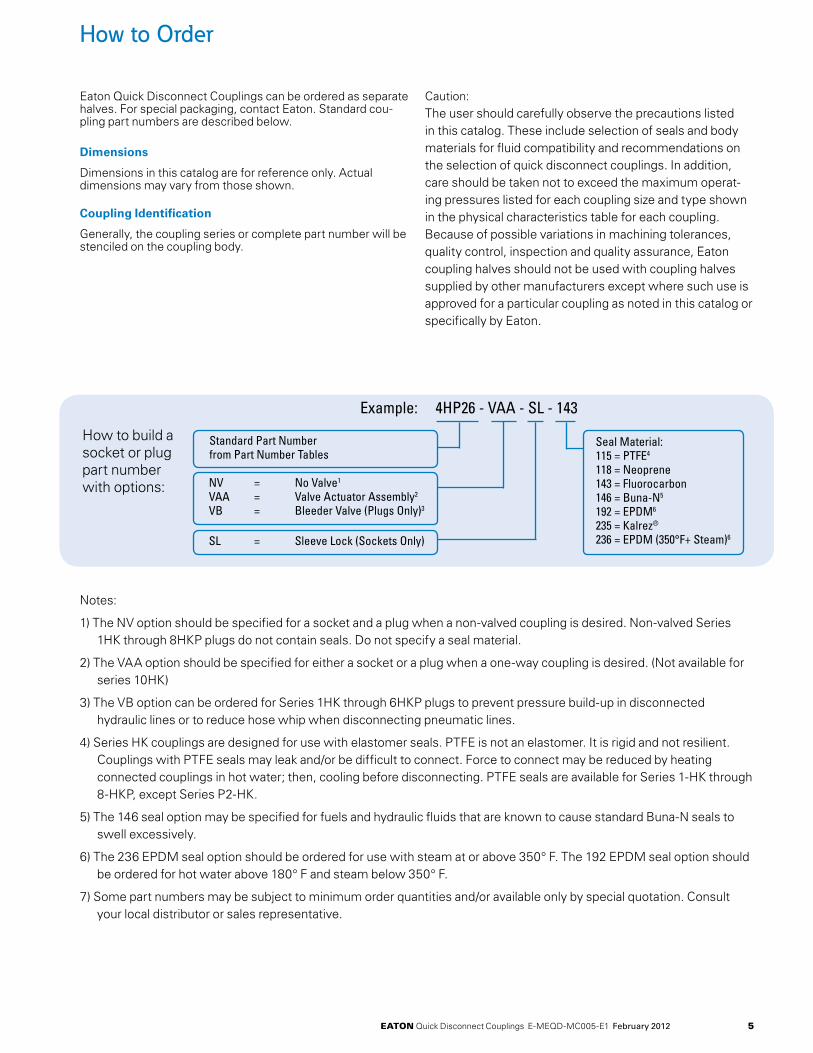
Eaton Quick Disconnect Couplings can be ordered as separate halves. For special packaging, contact Eaton. Standard cou-pling part numbers are described below.
Dimensions
Dimensions in this catalog are for reference only. Actual dimensions may vary from those shown.
Coupling Identification
Generally, the coupling series or complete part number will be stenciled on the coupling body.
Caution: The user should carefully observe the precautions listed in this catalog. These include selection of seals and body materials for fluid compatibility and recommendations on the selection of quick disconnect couplings. In addition, care should be taken not to exceed the maximum operat-ing pressures listed for each coupling size and type shown in the physical characteristics table for each coupling. Because of possible variations in machining tolerances, quality control, inspection and quality assurance, Eaton coupling halves should not be used with coupling halves supplied by other manufacturers except where such use is approved for a particular coupling as noted in this catalog or specifically by Eaton.
How to build a socket or plug part number with options:
Example: 4HP26 - VAA - SL - 143
Standard Part Number from Part Number Tables
NV = No Valve1 VAA = Valve Actuator Assembly2
VB = Bleeder Valve (Plugs Only)3
Seal Material:115 = PTFE4 118 = Neoprene 143 = Fluorocarbon 146 = Buna-N5
192 = EPDM6 235 = Kalrez®
236 = EPDM (350°F+ Steam)6SL = Sleeve Lock (Sockets Only)
eaton Quick Disconnect Couplings E-MEQD-MC005-E1 February 2012 5
Notes:
1) The NV option should be specified for a socket and a plug when a non-valved coupling is desired. Non-valved Series 1HK through 8HKP plugs do not contain seals. Do not specify a seal material.
2) The VAA option should be specified for either a socket or a plug when a one-way coupling is desired. (Not available for series 10HK)
3) The VB option can be ordered for Series 1HK through 6HKP plugs to prevent pressure build-up in disconnected hydraulic lines or to reduce hose whip when disconnecting pneumatic lines.
4) Series HK couplings are designed for use with elastomer seals. PTFE is not an elastomer. It is rigid and not resilient. Couplings with PTFE seals may leak and/or be difficult to connect. Force to connect may be reduced by heating connected couplings in hot water; then, cooling before disconnecting. PTFE seals are available for Series 1-HK through 8-HKP, except Series P2-HK.
5) The 146 seal option may be specified for fuels and hydraulic fluids that are known to cause standard Buna-N seals to swell excessively.
6) The 236 EPDM seal option should be ordered for use with steam at or above 350° F. The 192 EPDM seal option should be ordered for hot water above 180° F and steam below 350° F.
7) Some part numbers may be subject to minimum order quantities and/or available only by special quotation. Consult your local distributor or sales representative.

Safety Information for Eaton Quick Disconnect Couplings
1.0 General Instructions.
1.1 Scope. The scope of this safety bulletin is to warn against improper selection, use, installation, etc. of Eaton coupling products.
1.2 Distribution. A copy of this safety bulletin should be distributed to all individuals responsible for using and/or selecting Eaton coupling products.
1.3 Fail-Safe. Design all systems and equipment for fail-safe operation such that failure of any component does not result in personal injury and/or property damage.
1.4 User Responsibility. It is the sole responsibility of the user to select and determine that the Eaton product is compatible with the end use application. The user is responsible for reading and following this safety bulletin as well as any instructions or literature on the Eaton product being used. The user must provide necessary product warnings for Eaton couplings products, used with systems or equipment, to the operators of the systems or equipment.
1.5 Usage with other Manufacturers’ Products. When using Eaton coupling products with other manufacturers’ adapters, hoses, etc., do not exceed the lowest pressure rating of any of the components being used or rupture may result.
2.0 Selection of Eaton Couplings.
2.1 Pressure. Ensure that the maximum operating pressure of the system or equipment does not exceed the rated operating pressure of the Eaton coupling product or rupture may result.
2.2 Fluid Compatibility. Verify that all components (seals, metals, etc.) are compatible with the fluid being conveyed. Failure to do so may result in high speed fluid discharge and/or leakage of fluids which may be flammable, toxic, at extreme temperatures, or otherwise harmful.
2.3 Temperature. Ensure that the maximum operating temperature of the system or equipment does not exceed the rated operating temperature of the Eaton coupling product (including seals) or rupture may result.
2.4 Coupling Size. Use properly sized couplings such that there is not a large pressure drop across them thus avoiding system damage due to excessive heat generation or failure of internal components.
2.5 Sleeve Lock. Use sleeve locks or threaded couplings where there is the possibility of accidental disconnection. Failure to utilize sleeve locks or threaded couplings in these applications may result in hose whip, expelled components, high speed fluid discharge, system damage, or leakage of fluids which may be flammable, toxic, at extreme temperatures, or otherwise harmful.
2.6 Connect or Disconnect Under Pressure. If connection and/or disconnection of couplings under pressure is a requirement, only use couplings designed for connection/disconnection under pressure. Failure to utilize this type of coupling in that application may result in hose whip, expelled components, high speed fluid discharge, and/or system damage. Be certain not to confuse the rated operating pressure with the rated connect/disconnect under pressure.
2.7 Environment. Ensure that Eaton couplings are compatible with the surrounding environment. The surrounding environment may be heat, salt water, moisture, chemicals, and the like. Failure to protect against an adverse environment may cause system damage, premature failure, and/or leakage of fluids which may be flammable, toxic, at extreme temperatures, or otherwise harmful.
2.8 External Loads. Avoid any external loads such as side loads, tensile loads, vibration, etc. Failure to do so may result in accidental disconnection, premature failure, system damage, and/or leakage of fluids which may be flammable, toxic, at extreme temperatures, or otherwise harmful.
2.9 Welding & Brazing. Extreme heating of plated products above +450°F (+232°C) such as welding, brazing, baking, etc., where the plating is burned off, may result in the release of deadly gases.
3.0 Installation of Eaton Couplings.
3.1 Inspection of Product. Prior to installation, ensure that the Eaton product meets all of the requirements of the system and/or equipment it is to be used on. Ensure you have the correct part number, function test the coupling by connecting it with a mating half. The function test should result in smooth, non-binding operation or premature failure may result.
3.2 Cleanliness. Use end caps and plugs to reduce the risk of system contamination or damage to critical sealing surfaces. Failure to do so may result in leakage of fluids which may be flammable, toxic, at extreme temperatures, or otherwise harmful. Caps and plugs are not a secondary seal unless explicitly noted.
3.3 Location. Place Eaton couplings in a safe location such as not to expose the user to personal injury (slippage, tripping, falling, etc.) during installation, connection, disconnection and maintenance.
4.0 Product Maintenance. A maintenance schedule should be put in place to ensure that Eaton couplings are functioning properly. Eaton is not responsible for product failures resulting from modification or improper maintenance.
4.1 Inspection. Visually inspect to ensure that there is no leakage, cracked components, corrosion build-up, contamination build-up, wear, etc. If any abnormality is encountered, the coupling should be replaced immediately.
eaton Quick Disconnect Couplings E-MEQD-MC005-E1 February 20126

Fluid Compatibility
This chart indicates the suitability of various elastomers and metals for use with fluids to be conveyed. It is intended for use with Eaton couplings and should not be used to determine compatibility for other products. It is intended as a guide only and is not a guarantee. Final selection of the proper seal or material of metal components is further dependent on many factors including pressure, fluid and ambient temperature, concentration, duration of exposure, etc.
How to Use the Chart
1. Both the elastomer and the metal must be considered when determining suitability of combination for a coupling.
2. Locate the fluid to be conveyed and determine the suitability of the elastomeric and metal components according to the resistance rating shown for each.
3. Dimensional and operation specifications for each coupling can be found on the catalog pages.
4. Information on seal options for couplings, and how to specify them, are shown in the respective sections of this catalog.
5. Be sure to check the table below for maximum operating temperature range of the elastomer desired.
6. For further details on the products shown in this catalog, and their applications, consult your Eaton Sales Representative or Eaton Technical Support.
7. Coupling component materials may differ from body material. Refer to specific catalog pages.
Seal Elastomer Data*
Max. operation Seal elastomer** temperature Range
Buna-N -40°F to +250°F (-40°C to +121°C)Neoprene -65°F to +212°F (-54°C to +100°C)EPR (Ethylene -65°F to +300°F Propylene Rubber) (-54°C to +149°C)Flourocarbon -15°F to +400°F (-29°C to +204°C)
* For reference only, based on Eaton recommended temperatures.
**For seals not listed contact Eaton.
Contact Eaton technical support for further information.
E=ExcellentG=GoodC=ConditionalU=Unsatisfactory
Resistance Rating Key
E = Excellent – Fluid has little or no effect
G = Good – Fluid has minor to moderate effect
C = Conditional – Service conditions should be described to Eaton for determination of suitability for application
U = Unsatisfactory
The differences between ratings “E” and “G” are relative. Both indicate satisfactory service. Where there is a choice, the materials rated “E” may be expected to give better or longer service than those rated “G”.
Bu
na-
N
Neo
pre
ne
EP
R/E
PD
M
Flo
uro
carb
on
Ste
el
Bra
ss
Sta
inle
ss S
teel
Alu
min
um
Bu
na-
N
Neo
pre
ne
EP
R/E
PD
M
Flo
uro
carb
on
Ste
el
Bra
ss
Sta
inle
ss S
teel
Alu
min
um
Acetaldehyde U C C U G E E EAcetic Acid, 10% U U E G U U C CAcetic Acid, Glacial U U C U U U C CAcetone U U G U E E E EAcetophenone U U E U E E E CAcetyl Acetone U U G U U C C CAcetyl Chloride U U U E C C C UAcetylene (1) G U G E E E E EAir, Hot (Up to +160°F) E E E E E E E EAir, Hot (161°F – 200°F) C G E E E E E EAir, Hot (201°F – 300°F) U U G E E E E EAir Wet, below 160°F E E E E U G E EAluminum Chloride, 10% aq E E E E U U U UAluminum Fluoride, 10% aq E E E E U U U EAluminum Nitrate, 10% aq E E E E U U C C
Aluminum Sulfate, 10% aq E E E E U C E CAlums, 10% aq E E E E U C E CAmmonia, Cold E E E U E U E EAmmonia, Hot U G G U E U E EAmmonia, Anhydrous G G E U E U E EAmmonia, Aqueous E E E U E U E EAmmonium Carbonate, 10% aq U E E U C U C CAmmonium Chloride, 10% aq E E E U U U C UAmmonium Hydroxide, 10% aq C C E C G U C CAmmonium Nitrate, 10% aq E G E U G U G GAmmonium Phosphate, 10% aq E E E – U C G UAmmonium Sulfate/Sulfide, 10% aq E E E U U U G UAmyl Acetate U U G U E E E EAmyl Alcohol G C E G G G E UAniline, Aniline Oil U U G U E U E G
Fluid Seals Metal Fluid Seals Metal
This charts below are intended for reference use only. The information in this chart pertains strictly to material compatibility and is not intended to be used as an application guide.
eaton Quick Disconnect Couplings E-MEQD-MC005-E1 February 2012 7

Bu
na-
N
Neo
pre
ne
EP
R/E
PD
M
Flo
uro
carb
on
Ste
el
Bra
ss
Sta
inle
ss S
teel
Alu
min
um
Bu
na-
N
Neo
pre
ne
EP
R/E
PD
M
Flo
uro
carb
on
Ste
el
Bra
ss
Sta
inle
ss S
teel
Alu
min
um
Fluid Seals Metal Fluid Seals Metal
Aniline Dyes U G G G U C G CAsphalt, < 200°F G C U E E G E CIRM 901 Oil E E C E E E E EIRM 902 Oil E G U E E E E EIRM 903 Oil E C U E E E E EAutomatic Trans. Fluid E C U E E E E EBarium Chloride, 10% aq E E E E U G G GBarium Hydroxide, 105 aq E E E E G U G UBarium Sulfide, 10% aq E E E E C U G UBenzene, Benzol U U U E G E E GBenzoic Acid U U U E U G G GBenzyl Alcohol U G G E E G E GBioDiesel (<B20) G C U E BioDiesel (>B20) G C U E Black Sulfate Liquor C C C E E C E UBlast Furnace Gas U U U E E C E UBorax, 10% aq G G E E E E E GBoric Acid, 10% aq G G G E U G C CBrine E G E E U G G UBromine, Dry U U U E U C U CButane E C U E E E E EButyl Acetate U U G U E E E EButyl Alcohol E E G E G G G GButyl Cellosolve U U G U E E E EButylene (Butene) C U U E E E E EButyl Stearate G U U E G G G GButyraldehyde U U G U E E E ECalcium Acetate, 10% aq G G E U G G G CCalcium Bisulfate, 10% aq E E U E U C C UCalcium Chloride, 10% aq E E E E G G G CCalcium Hydroxide, 10% aq E E E E G G G UCalcium Hypochlorite, 10% aq U U E E U G C UCalcium Nitrate, 10% aq E E E E G G G GCarbitol G G G G E E E ECarbolic Acid (Phenol) U U G E U E E –Carbonic Acid G E E E U C E GCarbon Dioxide, Dry Gas G G E E E E E ECarbon Disulfide U U U E G G G ECarbon Monoxide G G E E E E E ECarbon Tetrachloride U U U E U G G UCastor Oil E E G E E E E ECellosolve Acetate U U G U U U E GChina Wood Oil (Tung Oil) G G U E E G E EChlorine Gas, Dry U U U G C C C CChloroacetic Acid U U G U U U U UChloroacetone U U E U G G G UChlorobenzene U U U G G G G GChloroform U U U E G G G GO-Chlorophenol U U U E G G G UChlosulfonic Acid U U U U G U G GChrome Plating Solution U U G E C U U U
Chromic Acid U U C E C U U UCitric Acid E E E E C C C CCoke Oven Gas U U U E E C E UCopper Chloride, 10% aq E E E E U U U UCopper Cyanide, 10% aq E E E E E U G UCopper Sulfate, 10% aq E E E E U C G UCotton Seed Oil E G C E E E E ECreosote (Coal Tar) G C U E E C E ECrude Oil E G U E G U G UCyclohexanol E G U E E E E CCyclohexanone U U G U E E E CDetergent/Water Solution E E E E G E E EDiacetone Alchohol (Acetol) U U E U E E E EDibenzyl Ether U U G U G G G GDiesel Oil E C U E E E E EDiethylamine G G G U E U E –Dioctyl Phthalate (DOP) U U G G E E E EDOT #3 / #4 Brake fluid C U E U E C E EDowtherm A&E U U U E G U E EEthyl Alcohol (Ethanol) E E E E E E E GEthyl Acetate U U G U E E E EEthyl Benzene U U U E E G G GEthyl Cellulose G G G U E G G GEthyl Chloride U U U E E E E GEthylene Dichloride U U U G G C G GEthylene Glycol E E E E U G E EFerric Chloride, 10% aq E G E E U U U UFerric Nitrate, 10% aq E E E E U U G UFerric Sulfate, 10% aq G G G E U U E UFormaldehyde C C G G E E E GFormic Acid C G E U U C C CFuel Oil E C U E E E E EFurfural C C G U G G G GGallic Acid, Solution G G G E U – G CGasoline E U U E E E E EGasohol G U U E E E E GGlycerine/Glycerol E E E E E G E EGreen Sulfate Liquor G G E E U U E UHelium (1) E E E E E E E EHeptane E G U E E E E EHexaldehyde U G G U G G E EHexane E G U E E E E EHydraulic Oils, petroleum based G C U E E E E E Ester Blend E U U E E E E E Phos. Ester/Petroleum Blend U U U C E E E E Silicone Oils E E E E E E E E Straight Petroleum Base E C U E E E E E Straight Phosphate Ester U U G C E E E E Water Glycol E E E E E E E G Water Petroleum Emulsion E G U E C E E GHydrobromic Acid U U E E E U E E
Fluid Compatibility
E=ExcellentG=GoodC=ConditionalU=Unsatisfactory
eaton Quick Disconnect Couplings E-MEQD-MC005-E1 February 20128

Bu
na-
N
Neo
pre
ne
EP
R/E
PD
M
Flo
uro
carb
on
Ste
el
Bra
ss
Sta
inle
ss S
teel
Alu
min
um
Bu
na-
N
Neo
pre
ne
EP
R/E
PD
M
Flo
uro
carb
on
Ste
el
Bra
ss
Sta
inle
ss S
teel
Alu
min
um
Fluid Seals Metal Fluid Seals Metal
Hydrochloric Acid, Cold U U G E U U U UHydrocyanic Acid C C E E E E G EHydrofluoric Acid U U C U U U U UHydrofluorosilic Acid G G E E U U U UHydrogen E E E E E E E EHydrogen Peroxide G G G E U U G EHydrogen Sulfide, Dry U G E U E G G GIsocyanate U U G E G – G –Iso Octane E G U E E E E EIsopropyl Acetate U U G U E – E EIsopropyl Alcohol G G E E E E E GIsopropyl Ether G U U U G G G –JP-4, JP-5 E U U E E E E EKerosene E U U E E E E ELacquer/Lacquer Solvents U U U U U E E ELime Sulfur U E E E G U G –Linseed Oil E G U E E E E ELPG E G U E E E E EMagnesium Chloride, 10% aq E E E E E C C GMagnesium Hydroxide, 10% aq G G E E E G E GMagnesium Sulfate, 10% aq E E E E E E E EMaleic Acid U U U E E G G GMaleic Anhydride U U U E G U E GMalic Acid G G U G U – E GMercuric Chloride E E E E U U U UMercury E E E E E U E UMethanol G G E U G G E CMethyl Bromide G U U E E E G UMethyl Chloride U U U E E E E UMethyl Butyl Ketone U U E U E E E –Methyl Ethyl Ketone U U E U G G G GMethylene Chloride U U U G G G G GMethyl Isobutyl Ketone U U U U G G G GMethyl Isopropyl Ketone U U U U G G G GMethyl Salicylate U U C U E G G EMIL-L-2104 E G U E E E E –MIL-H-5606 E G U E E E E EMIL-H-6083 E E U E E E E –MIL-L-7808 G U U E G G E –MIL-L-23699 G U U E E E E EMIL-H-46170 E G U E E E E –MIL-H-83282 E U U E E E E –Mineral Oils E C U E E E E ENaphtha C U U E – – – –Naphthalene U U U E E G E GNaphthenic Acid C U U E – G E GNatural Gas E E U E G G G GNickel Acetate, 10% aq C C E G G C E GNickel Chloride, 10% aq E G E E U U G UNickel Sulfate, 10% aq E E E E U G G UNitric Acid, to 10% U U U E U U E U
Nitric Acid, over 10% U U U G U U E CNitrobenzene U U U G E G E ENitrogen E E E E E E E EOctyl Alcohol E E E E E E E EOleic Acid U U C G C E G COleum, fuming sulfuric acid U U U E E E E EOrtho-Dichlorobenzene U U U E G G G GOxalic Acid, 10% aq G G E E U C C COxygen – – E E G G G GPalmitic Acid E G G E G – E GPara-Dichlorobenzene U U U E G G G GPentane E E U E G G G EPerchloric Acid E G G E U U U UPerchloroethylene U U U E C G G GPetroleum Base Oils E G U E E E E EPhenol (Carbolic Acid) U U G E U E E EPhosphate Ester U U G C E E E EPhosphoric Acid 20% U U G E U E U CPhosphorous Trichloride U U E E C U C EPotassium Acetate, 10% aq G G E U C G C UPotassium Chloride, 10% aq E E E E E C E UPotassium Cyanide, 10% aq E E E E C U G UPotassium Dichromate, 10% aq E E E E C C C CPotassium Hydroxide, to 10% G G E G G G G UPotassium Hydroxide, over 10% C C E U G G G UPotassium Nitrate, 10% aq E E E E G G E GPotassium Sulfate, 10% aq E E E E – – – –Propane (Liquified) C G – E E E E EPropyl Acetate U U G U E – E EPropyl Alcohol E E E E E E E EPropylene U U U E E E E ERapeseed oil (B100) G C U E Refrigerant R-12 G E C E E E E ERefrigerant R-13 G E C E E E E ERefrigerant R-22 U E C U E E E ERefrigerant R-134a E C G U E E E ESewage E E E E G G G GSilicone Oils E E E E E E E ESoap (Water Solutions) E E E E E E E USodium Acetate, 10% aq G G E U E E G ESodium Bicarbonate, 10% aq E E E E G G E GSodium Borate, 10% aq E E E E E E E GSodium Carbonate, 10% aq E E E E E G E USodium Chloride, 10% aq E E E E U C C CSodium Cyanide, 10% aq E E E E E – C USodium Hydroxide, to 10% U G E E C G C USodium Hydroxide, over 10% U U G E C C C USodium Hypochlorite, 10% aq C C E C U U U USodium Metaphosphate, 10% aq E E E E E G G USodium Nitrate, 10% aq G G E – E C E ESodium Perborate, 10% aq G G E E C U C U
Fluid Compatibility
E=ExcellentG=GoodC=ConditionalU=Unsatisfactory
eaton Quick Disconnect Couplings E-MEQD-MC005-E1 February 2012 9

Bu
na-
N
Neo
pre
ne
EP
R/E
PD
M
Flo
uro
carb
on
Ste
el
Bra
ss
Sta
inle
ss S
teel
Alu
min
um
Bu
na-
N
Neo
pre
ne
EP
R/E
PD
M
Flo
uro
carb
on
Ste
el
Bra
ss
Sta
inle
ss S
teel
Alu
min
um
Fluid Seals Metal Fluid Seals Metal
Fluid Compatibility
E=ExcellentG=GoodC=ConditionalU=Unsatisfactory
Sodium Peroxide, 10% aq G G E E U U C CSodium Phosphates, 10% aq E E E E U E G USodium Silicate, 10% aq E E E E E E E ESodium Sulfate, 10% aq E E E E C G G GSodium Sulfide, 10% aq E E E E C U C USodium Thiosulfate, 10% aq G E E E U U C GSoy Bean Oil (B100) E C U E E E E EStannic Chloride E G E E U U U USteam (up to 388°F) U U C C E E E GStearic Acid G G G E C C E CStoddard Solvent E G U E E E E EStyrene U U U G E E E ESulfur, Slurry U E E E E U G ESulfur Chloride, Wet U U U E G – G GSulfur Dioxide, Dry U U G E E G G ESulfur Trioxide U U G E G C G GSulfuric Acid, to 10% U G U E U G C –Sulfuric Acid, over 10% U U U G C C C USulfurous Acid C C U G U C C CTannic Acid G E E E E E E CTar (Bituminous) G U U E E G E E
Tartaric Acid E G G E U C C ETertiary Butyl Alcohol G G G E G G G GTitanium Tetrachloride C U U E E U G UToluene (Toluol) U U U E E E E ETrichlorethylene U U U E E G E ETricresyl Phosphate U U E G E – C –Triethanolamine E U E U E U E ETung Oil G G U E E G E ETurpentine G U U E G G G GVarnish G U U E E G E EVinyl Chloride U U U E E U C EWater (to +150°F) E E E E C G E GWater (+151°F to +200°F) E E E E C G E GWater (+201°F to +350°F) U U G G C G E GWater Glycol E E E E E E E GWater Petroleum Emulsion E G U E C E E GXylene U U U E E E E EZinc Chloride, 10% aq E E E E E U U CZinc Sulfate, 10% aq E E E E U C G C
eaton Quick Disconnect Couplings E-MEQD-MC005-E1 February 201210

The HK Series Coupling sets the industry standard for ISO-B Couplings and came to Eaton with the recent aquisition of the Hansen™ and Gromelle™ businesses. The HK Series features a rugged ball latch mechanism with automatic self-sealing poppet valves in a wide array of port configurations and multiple valved and non-valved configurations.
• Meetsdimensionalrequirementsto ISO standard 7241/1 Series B
• Thecouplingthatsettheindustrystandard
• Self-sealingpoppetvalvedesignprovides excellent high and low pressure sealing
• Standardsealmaterial-Buna-N.Seal options available in PTFE, Neoprene, Fluorocarbon, EPDM, and Kalrez
• Standardbodymaterial-zinc-trivalent chromate plated steel with stainless steel springs, balls and retaining rings.
• PTFEbackupringsinsockets(females)
Product Features
Physical Characteristics Max. Body operating Rated Size ISo Pressure Flow air Inclusion Fluid Loss
mm bar (psi) L/min (gpm) cc. max. cc. max.
1/8 5 275 4,000 3 0.8 0.6 0.51/4 6.3 345 5,000 12 3 1.2 0.93/8 10 255 3,700 23 6 2.9 2.11/2 12.5 345 5,000 45 12 3.6 3.53/4 20 275 4,000 100 26 11.5 9.31 25 275 4,000 189 50 18.0 16.91--1/4** -- 118 1,700 288 76 48.0 48.01--1/2 40 152 2,200 375 99 91.3 91.32--1/2 50 104 1,500 757 200 209.9 209.9*For questions related to vacuum please contact Eaton.** No ISO Standard available for the 10HK
•Agriculture•HydraulicTool•GeneralIndustry•Construction•FluidTransfer•Transportation•Military•LawEnforcement/Rescue•Chemical•OilandGas•ConsumerProducts•HVAC•FoodandBeverage•Trucks•Aerospace
•Medical
HK Series ISO 7241/1 BSteel
eaton Quick Disconnect Couplings E-MEQD-MC005-E1 February 2012 11
Applications & Markets

HK Series ISO 7241/1 BSteelSockets(Female) Dimensions (mm) Dimensions (inches) Part Number Body Size ISO Thread Size (Female) Across Across HK1-8 Series (inch) (mm) NPTF BSPP SAE A B Flats A B Flats1H11 1/8 5 1/8-27 - - 1.91 0.98 0.56 48.5 24.9 14.21H4 1/8 5 - - 7/16-20 2.06 0.98 0.69 52.3 24.9 17.5 2H16 1/4 6.3 1/4-18 - - 2.26 1.14 0.75 57.4 29.0 19.1 2H16BS 1/4 6.3 - 1/4-19 - 2.31 1.14 0.75 58.7 29.0 19.1 2H6 1/4 6.3 - - 9/16-18 2.40 1.14 0.88 61.0 29.0 22.4 3H21 3/8 10 3/8-18 - - 2.56 1.42 0.88 65.0 36.1 22.4 3H21BS 3/8 10 - 3/8-19 - 2.56 1.42 0.88 65.0 36.1 22.4 3H8 3/8 10 - - 3/4-16 2.74 1.42 1.00 69.6 36.1 25.4 4HP26 1/2 12.5 1/2-14 - - 2.96 1.86 1.13 75.2 47.2 28.7 4HP26BS 1/2 12.5 - 1/2-14 - 2.96 1.86 1.13 75.2 47.2 28.7 4HP10 1/2 12.5 - - 7/8-14 3.05 1.86 1.25 77.5 47.2 31.8 6HP31 3/4 20 3/4-14 - - 3.48 2.22 1.31 88.4 56.4 33.3 6HP31BS 3/4 20 - 3/4-14 - 3.48 2.22 1.31 88.4 56.4 33.3 6HP12 3/4 20 - - 11/16-12 3.67 2.22 1.38 93.2 56.4 35.1 8HP36 1 25 1-111/2 - - 4.13 2.61 1.75 104.9 66.3 44.5 8HP36BS 1 25 - 1-11 - 4.13 2.61 1.75 104.9 66.3 44.5 8HP16 1 25 - - 15/16-12 4.13 2.61 1.88 104.9 66.3 47.8See Figure 1 A=Overall Length B=Maximum Diameter
Part Number Body Size ISO Thread Size (Female) Dimensions (inches) Dimensions (mm) HK10/12/20 Series (inch) (mm) NPTF BSPP A B HEX A B HEX 10H41* 11/4 - 11/4-111/2 - 4.51 2.73 2.38 114.6 69.3 60.5 10H41BS* 11/4 - - 11/4-11 4.51 2.73 2.38 114.6 69.3 60.5 12H41 11/2 40 11/4-111/2 - 4.82 3.23 2.38 122.4 82.0 60.5 12H41BS 11/2 40 - 11/4-11 4.82 3.23 2.38 122.4 82.0 60.5 12H46 11/2 40 11/2-111/2 - 4.82 3.23 2.38 122.4 82.0 60.5 12H46BS 11/2 40 - 11/2-11 4.82 3.23 2.38 122.4 82.0 60.5 20H51 21/2 50 2-111/2 - 5.55 4.11 3.75 141.0 104.4 95.3 20H51BS 21/2 50 - 2-11 5.55 4.11 3.75 141.0 104.4 95.3 20H56 21/2 50 21/2-8 - 6.14 4.11 3.75 156.0 104.4 95.3 20H56BS 21/2 50 - 21/2-11 6.14 4.11 3.75 156.0 104.4 95.3 20H61 21/2 50 3-8 - 7.00 4.11 4.00 177.8 104.4 101.6 20H61BS 21/2 50 - 3-11 7.00 4.11 4.00 177.8 104.4 101.6 See Figure 2 A=Overall Length B=Maximum Diameter* ISO 7241-1 Series B does not include 1-1/4 inch body size couplings;therefore, Series 10HK is not covered by this standard To obtain connected length of coupling add Dimensions A and E together.
Socket
eaton Quick Disconnect Couplings E-MEQD-MC005-E1 February 201212
Fig. 1
Fig. 2

Plug
HK Series ISO 7241/1 BSteel
Dust Plugs and Dust Caps AccessoriesCoupling Series
Plug Dust Cap Part No. Socket Dust Plug Part No.Metal Vinyl Metal Vinyl
1HK PDC1HK* PPDC1HK SDC1HK* PSDC1HK2HK PDC2HK* PPDC2HK SDC2HK* PSDC2HK3HK PDC3HK* PPDC3HK SDC3HK* PSDC3HK4HK PDC4HK** PPDC4HK SDC4HK** PSDC4HK6HK PDC6HK** PPDC6HK SDC6HK** PSDC6HK8HK PDC8HK** PPDC8HK SDC8HK** PSDC8HK12HK PDC12HK* SDC12HK*20HK PDC20HK* SDC20HK*
Vinyl Dust Plug
Vinyl Dust Cap
Metal Dust Cap
Metal Dust Plug
* Brass ** Aluminum
eaton Quick Disconnect Couplings E-MEQD-MC005-E1 February 2012 13
Fig. 3 Fig. 4
Plugs(Male) Part Number Body Size ISO Thread Size (Female) Dimensions (inches) Dimensions (mm) HK1-8 Series High Impulse (inch) (mm) NPTF BSPP SAE C D E Hex C D E Hex 1K11 - 1/8 5 1/8-27 - - 1.26 0.65 0.44 0.56 32.0 16.5 11.2 14.21K4 - 1/8 5 - - 7/16-20 1.41 0.79 0.59 0.69 35.8 20.1 15.0 17.52K16 2K16C 1/4 6.3 1/4-18 - - 1.52 0.87 0.56 0.75 38.6 22.1 14.2 19.12K16BS - 1/4 6.3 - 1/4-19 - 1.52 0.87 0.56 0.75 38.6 22.1 14.2 19.12K6 2K6C 1/4 6.3 - - 9/16-18 1.66 1.01 0.70 0.88 42.2 25.7 17.8 22.43K21 3K21C 3/8 10 3/8-18 - - 1.76 1.01 0.61 0.88 44.7 25.7 15.5 22.43K21BS - 3/8 10 - 3/8-19 - 1.76 1.01 0.61 0.88 44.7 25.7 15.5 22.43K8 3K8C 3/8 10 - - 3/4-16 1.94 1.15 0.79 1.00 49.3 29.2 20.1 25.44KP26 4KP26 1/2 12.5 1/2-14 - - 2.03 1.30 0.76 1.13 51.6 33.0 19.3 28.74KP26BS 4KP26BS 1/2 12.5 - 1/2-14 - 2.03 1.30 0.76 1.13 51.6 33.0 19.3 28.74KP10 4KP10 1/2 12.5 - - 7/8-14 2.11 1.37 0.84 1.19 53.6 34.8 21.3 30.26KP31 6KP31 3/4 20 3/4-14 - - 2.36 1.52 0.71 1.31 59.9 38.6 18.0 33.36KP31BS 6KP31BS 3/4 20 - 3/4-14 - 2.36 1.52 0.71 1.31 59.9 38.6 18.0 33.36KP12 6KP12 3/4 20 - - 11/16-12 2.54 1.59 0.89 1.38 64.5 40.4 22.6 35.18KP36 8KP36 1 25 1-111/2 - - 2.85 1.88 0.97 1.63 72.4 47.8 24.6 41.48KP36BS 8KP36BS 1 25 - 1-11 - 2.85 1.88 0.97 1.63 72.4 47.8 24.6 41.48KP16 8KP16 1 25 - - 15/16-12 2.85 2.17 0.97 1.88 72.4 55.1 24.6 47.8See Figure 3 C=Overall Length D=Maximum Diameter E=Exposed Length when Connected To obtain connected length of coupling add Dimensions A and E together. Part Number Body Size ISO Thread Size (Female) Dimensions (inches) Dimensions (mm) HK1-8 Series High Impulse (inch) (mm) NPTF BSPP C D E Hex C D E Hex 10K41* - 11/4 - 11/4-111/2 - 4.25 2.74 2.33 2.38 108.0 69.6 59.2 60.510K41BS* - 11/4 - - 1-1/4-11 4.25 2.74 2.33 2.38 108.0 69.6 59.2 60.5
12K41 12K41C 11/2 40 11/4-111/2 - 4.76 2.74 2.67 2.38 12.0.9 69.6 67.8 60.512K41BS 12K41CBS 11/2 40 - 1-1/4-11 4.76 2.74 2.67 2.38 120.9 69.6 67.8 60.512K46 12K46C 11/2 40 11/2-111/2 - 4.76 2.74 2.67 2.38 120.9 69.6 67.8 60.512K46BS 12K46CBS 11/2 40 - 1-1/2-11 4.76 2.74 2.67 2.38 120.9 69.6 67.8 60.520K51 20K51C 21/2 50 2-111/2 - 5.49 4.33 2.97 3.75 139.4 110.0 75.4 95.320K51BS 20K51CBS 21/2 50 - 2-11 5.49 4.33 2.97 3.75 139.4 110.0 75.4 95.320K56 20K56C 21/2 50 21/2-8 - 6.08 4.33 3.56 3.75 154.4 110.0 90.4 95.320K56BS 20K56CBS 21/2 50 - 2-1/2-11 6.08 4.33 3.56 3.75 154.4 110.0 90.4 95.320K61 20K61C 21/2 50 3-8 - 6.94 4.62 4.42 4.00 176.3 117.3 112.3 101.620K61BS 20K61CBS 21/2 50 - 3-11 6.94 4.62 4.42 4.00 176.3 117.3 112.3 101.6See Figure 4 C=Overall Length D=Maximum Diameter E=Exposed Length when Connected* ISO 7241-1 Series B does not include 1-1/4 inch body size couplings;therefore, Series 10HK is not covered by this standard To obtain connected length of coupling add Dimensions A and E together.

Physical Characteristics Max. Body operating Rated Size ISo Pressure Flow air Inclusion Fluid Loss
(mm) bar (psi) L/min (gpm) cc. max. cc. max.
1/8 5 207 3,000 3 0.8 0.6 0.5 1/4 6.3 186 2,700 12 3 1.2 0.9 3/8 10 152 2,200 23 6 2.9 2.1 1/2 12.5 155 2,250 45 12 3.6 3.5 3/4 20 138 2,000 100 26 11.5 9.3 1 25 103 1,500 189 50 18.0 16.9 1-1/4** - 83 1,200 288 76 48.0 48.0 1-1/2 40 104 1,500 375 99 91.3 91.3 2-1/2 50 49 700 757 200 209.9 209.9
*For questions related to vacuum please contact Eaton.** No ISO Standard available for the 10HK
HK Series ISO 7241/1 BBrass
The HK brass is a general purpose industrial interchange coupling available in valved or non-valved designs, offered in brass for excelllent corrosion resistance in rugged applications where stainless steel is unacceptable. Features a ball latch mechanism with automatic self-sealing poppet valves.
• Meetsdimensionalrequirements to ISO standard 7241/1 Series B
• Brassconstructionwithstainless steel springs for greater corrosion resistance and fluid compatibility
• Self-sealingpoppetvalvesprovide excellent high and low pressure sealing
• Standardsealmaterial-Buna-N.Seal options available in PTFE, Neoprene, Fluorocarbon, EPDM, and Kalrez
Product Features
Applications & Markets
•Agriculture•HydraulicTool•GeneralIndustry•Construction•FluidTransfer•Chemical•OilandGas•Transportation•FoodandBeverage•Trucks•Nuclear
eaton Quick Disconnect Couplings E-MEQD-MC005-E1 February 201214

HK Series ISO 7241/1 BBrassSockets(Female) Dimensions (inches) Dimensions (mm) Part Number Body Size ISO Thread Size (Female) Across AcrossHK1-8 Series (inch) (mm) NPTF BSPP A B Flats A B FlatsB1H11 1/8 5 1/8-27 - 1.91 .98 .56 48.5 24.9 14.2B2H16 1/4 6.3 1/4-18 - 2.26 1.14 .75 57.4 29.0 19.1B2H16BS 1/4 6.3 - 1/4-19 2.31 1.14 .75 58.7 29.0 19.1B3H21 3/8 10 3/8-18 - 2.56 1.42 .88 65.0 36.1 22.4B3H21BS 3/8 10 - 3/8-19 2.56 1.42 .88 65.0 36.1 22.4B4HP26 1/2 12.5 1/2-14 - 2.96 1.86 1.13 75.2 47.2 28.7BAHP26BS 1/2 12.5 - 1/2-14 2.96 1.86 1.13 75.2 47.2 28.7B6HP31 3/4 20 3/4-14 - 3.48 2.22 1.31 88.4 56.4 3.3.3B6HP31BS 3/4 20 - 3/4-14 3.48 2.22 1.31 88.4 56.4 33.3B8HP36 1 25 1-111/2 - 4.13 2.61 1.75 104.9 66.3 44.5B8HP36BS 1 25 - 1-11 4.13 2.61 1.75 104.9 66.3 44.5See Figure 1 A=Overall Length B=Maximum Diameter
Part Number Body Size Thread Size (Female) Dimensions (inches) Dimensions (mm) HK10/12/20 Series (inch) NPTF BSPP A B HEX A B HEX B10H41* 11/4 11/4-11-1/2 - 4.51 2.73 2.38 114.6 69.3 60.5B12H41 11/2 11/4-11-1/2 - 4.82 3.23 2.38 122.4 82.0 60.5B12H41BS 11/2 - 11/4-11 4.82 3.23 2.38 122.4 82.0 60.5B12H46 11/2 11/2-11 - 4.82 3.23 2.38 122.4 82.0 60.5B12H46BS 11/2 - 11/2-11 4.82 3.23 2.38 122.4 82.0 60.5B20H51 21/2 2-111/2 - 5.55 4.11 3.75 141.0 104.4 95.3B20H51BS 21/2 - 2-11 5.55 4.11 3.75 141.0 104.4 95.3B20H56 21/2 2-1/2-8 - 6.14 4.11 3.75 156.0 104.4 95.3B20H56BS 21/2 - 21/2-11 6.14 4.11 3.75 156.0 104.4 95.3B20H61 21/2 3-8 - 7.00 4.11 4.00 177.8 104.4 101.6B20H61BS 21/2 - 3-11 7.00 4.11 4.00 177.8 104.4 101.6See Figure 2 A=Overall Length B=Maximum Diameter* ISO 7241-1 Series B does not include 1-1/4 inch body size couplings; therefore, Series 10HK is not covered by this standardTo obtain connected length of coupling add Dimensions A and E together.
Socket
eaton Quick Disconnect Couplings E-MEQD-MC005-E1 February 2012 15
Fig. 2Fig. 1
ISO(mm)-40404040505050505050

Plugs(Male) Part Number Body Size Thread Size (Female) Dimensions (inches) Dimensions (mm) HK1-8 Series (inch) NPTF BSPP C D E Hex C D E Hex
B1K11 1/8 1/8-27 - 1.26 0.65 0.44 0.56 32.0 16.5 11.2 14.2B2K16 1/4 1/4-18 - 1.52 0.87 0.56 0.75 38.6 22.1 14.2 19.1B2K16BS 1/4 - 1/4-19 1.52 0.87 0.56 0.75 38.6 22.1 14.2 19.1B3K21 3/8 3/8-18 - 1.76 1.01 0.61 0.88 44.7 25.7 15.5 22.4B3K21BS 3/8 - 3/8-19 1.76 1.01 0.61 0.88 44.7 25.7 15.5 22.4B4KP26 1/2 1/2-14 - 2.03 1.30 0.76 1.13 51.6 33.0 19.3 28.7B4KP26BS 1/2 - 1/2-14 2.03 1.30 0.76 1.13 51.6 33.0 19.3 28.7B6KP31 3/4 3/4-14 - 2.36 1.52 0.71 1.31 59.9 38.6 18.0 33.3B6KP31BS 3/4 - 3/4-14 2.36 1.52 0.71 1.31 59.9 38.6 18.0 33.3B8KP36 1 1-111/2 - 2.85 1.88 0.97 1.63 72.4 47.8 24.6 41.4B8KP36BS 1 - 1-11 2.85 1.88 0.97 1.63 72.4 47.8 24.6 41.4See Figure 3 C=Overall Length D=Maximum Diameter E=Exposed Length when Connected
Part Number Body Size Thread Size (Female) Dimensions (inches) Dimensions (mm) HK1-8 Series (inch) NPTF BSPP C D E Hex C D E Hex
B10K41* 11/4 11/4-111/2 - 4.25 2.74 2.33 2.38 108.0 69.6 59.2 60.5B12K41 11/2 11/4-111/2 - 4.76 2.74 2.67 2.38 120.9 69.6 67.8 60.5B12K41BS 11/2 - 11/4-11 4.76 2.74 2.67 2.38 120.9 69.6 67.8 60.5B12K46 11/2 11/2-111/2 - 4.76 2.74 2.67 2.38 120.9 69.6 67.8 60.5B12K46BS 11/2 - 11/2-11 4.76 2.74 2.67 2.38 120.9 69.6 67.8 60.5B20K51 21/2 2-111/2 - 5.49 4.33 2.97 3.75 139.4 110.0 75.4 95.3B20K51BS 21/2 - 2-11 5.49 4.33 2.97 3.75 139.4 110.0 75.4 95.3B20K56 21/2 21/2-8 - 6.08 4.33 3.56 3.75 154.4 110.0 90.4 95.3B20K56BS 21/2 - 21/2-11 6.08 4.33 3.56 3.75 154.4 110.0 90.4 95.3B20K61 21/2 3-8 - 6.94 4.62 4.42 4.00 176.3 117.3 112.3 101.6B20K61BS 21/2 - 3-11 6.94 4.62 4.42 4.00 176.3 117.3 112.3 101.6See Figure 4 C=Overall Length D=Maximum Diameter E=Exposed Length when Connected * ISO 7241-1 Series B does not include 1-1/4 inch body size couplings; therefore, Series 10HK is not covered by this standardTo obtain connected length of coupling add Dimensions A and E together.
HK Series ISO 7241/1 BBrass
Dust Plugs and Dust Caps AccessoriesCoupling Series
Plug Dust Cap Part No. Socket Dust Plug Part No.Metal Vinyl Metal Vinyl
1HK PDC1HK* PPDC1HK SDC1HK* PSDC1HK2HK PDC2HK* PPDC2HK SDC2HK* PSDC2HK3HK PDC3HK* PPDC3HK SDC3HK* PSDC3HK4HK PDC4HK** PPDC4HK SDC4HK** PSDC4HK6HK PDC6HK** PPDC6HK SDC6HK** PSDC6HK8HK PDC8HK** PPDC8HK SDC8HK** PSDC8HK12HK PDC12HK* SDC12HK*20HK PDC20HK* SDC20HK*
Vinyl Dust Plug
Vinyl Dust Cap
Metal Dust Cap
Metal Dust Plug
* Brass ** Aluminum
eaton Quick Disconnect Couplings E-MEQD-MC005-E1 February 201216
Fig. 4Fig. 3
ISO(mm)
56.36.3101012.512.520202525
ISO(mm)
-40404040505050505050

The HK stainless steel is a general purpose industrial interchange coupling available in valved or non-valved designs, offered in 303/316 grades of stainless steel for excellent corrosion resistance in rugged applications. Features a ball latch mechanism with automatic self-sealing poppet valves.
• Meetsdimensionalrequirementsto ISO standard 7241/1 Series B
• 303/316Stainlesssteelconstruction for greater corrosion resistance and fluid compatibility
• Self-sealingpoppetvalvesprovide excellent high and low pressure sealing
• Standardsealmaterial-Buna-N.Seal options available in PTFE, Neoprene, Fluorocarbon, EPDM, and Kalrez
• Standardbodymaterial-303or316 Stainless Steel
Product Features
Physical Characteristics Max. Body operating Rated Size Pressure Flow air Inclusion Fluid Loss
bar (psi) L/min (gpm) cc. max. cc. max.
1/8 344 5,000 3 0.8 0.6 0.51/4 255 3,700 12 3 1.2 0.93/8 255 3,700 23 6 2.9 2.1 1/2 293 4,250 45 12 3.6 3.53/4 242 3,500 100 26 11.5 9.31 207 3,000 189 50 18.0 16.91-1/4** 118 1,700 288 76 48.0 48.01-1/2 152 2,200 375 99 91.3 91.32-1/2 104 1,500 757 200 209.9 209.9*For questions related to vacuum please contact Eaton.** No ISO Standard available for the 10HK
•Agriculture•HydraulicTool•GeneralIndustry•Construction•FluidTransfer•Transportation•Military•LawEnforcement/Rescue•Chemical•OilandGas•ConsumerProducts•HVAC•FoodandBeverage•Trucks•Aerospace•Medical
HK Series ISO 7241/1 BStainless Steel
eaton Quick Disconnect Couplings E-MEQD-MC005-E1 February 2012 17
Applications & Markets
ISO(mm)56.31012.52025-4050

HK Series ISO 7241/1 BStainless Steel
Socket
eaton Quick Disconnect Couplings E-MEQD-MC005-E1 February 201218
Fig. 2Fig. 1
ISO(mm)
556.36.36.310101012.512.512.5202020252525
ISO(mm)--40404040505050505050
Sockets(Female) Part Number Dimensions (inches) Dimensions (mm) HK1-8 Series Body Size Thread Size (Female) Across Across 303 316 (inch) NPTF BSPP SAE A B Flats A B Flats
LL1H11 ML1H11 1/8 1/8-27 - - 1.91 0.98 0.56 48.5 24.9 14.2 LL1H4 - 1/8 - - 7/16-20 2.06 0.98 0.69 52.3 24.9 17.5 LL2H16 ML2H16 1/4 1/4-18 - - 2.26 1.14 0.75 57.4 29.0 19.1 LL2H16BS ML2H16BS 1/4 - 1/4-19 - 2.31 1.14 0.75 58.7 29.0 19.1 LL2H6 - 1/4 - - 9/16-18 2.40 1.14 0.88 61.0 29.0 22.4 LL3H21 ML3H21 3/8 3/8-18 - - 2.56 1.42 0.88 65.0 36.1 22.4 LL3H21BS ML3H21BS 3/8 - 3/8-19 - 2.56 1.42 0.88 65.0 36.1 22.4 LL3H8 - 3/8 - - 3/4-16 2.74 1.42 1.00 69.6 36.1 25.4 LL4HP26 ML4HP26 1/2 1/2-14 - - 2.96 1.86 1.13 75.2 47.2 28.7 LL4HP26BS ML4HP26BS 1/2 - 1/2-14 - 2.96 1.86 1.13 75.2 47.2 28.7 LL4HP10 - 1/2 - - 7/8-14 3.05 1.86 1.25 77.5 47.2 31.8 LL6HP31 ML6HP31 3/4 3/4-14 - - 3.48 2.22 1.31 88.4 56.4 33.3 LL6HP31BS ML6HP31BS 3/4 - 3/4-14 - 3.48 2.22 1.31 88.4 56.4 33.3 LL6HP12 - 3/4 - - 11/16-12 3.67 2.22 1.38 93.2 56.4 35.1 LL8HP36 ML8HP36 1 1-111/2 - - 4.13 2.61 1.75 104.9 66.3 44.5 LL8HP36BS ML8HP36BS 1 - 1-11 - 4.13 2.61 1.75 104.9 66.3 44.5 LL8HP16 - 1 - - 15/16-12 4.13 2.61 1.88 104.9 66.3 47.8See Figure 1 A=Overall Length B=Maximum Diameter Part Number HK 10/12/20 Series Body Size Thread Size (Female) Dimensions (inches) Dimensions (mm) 303 Stainless Steel (inch) NPTF BSPP A B HEX A B HEX LL10H41* 11/4 11/4-111/2 - 4.51 2.73 2.38 114.6 69.3 60.5 LL10H41BS* 11/4 - 11/4-11 4.51 2.73 2.38 114.6 69.3 60.5 LL12H41 11/2 11/4-111/2 - 4.82 3.23 2.38 122.4 82.0 60.5 LL12H41BS 11/2 - 11/4-11 4.82 3.23 2.38 122.4 82.0 60.5 LL12H46 11/2 11/2-111/2 - 4.82 3.23 2.38 122.4 82.0 60.5 LL12H46BS 11/2 - 11/2-11 4.82 3.23 2.38 122.4 82.0 60.5 LL20H51 21/2 2-111/2 - 5.55 4.11 3.75 141.0 104.4 95.3 LL20H51BS 21/2 - 2-11 5.55 4.11 3.75 141.0 104.4 95.3 LL20H56 21/2 21/2-8 - 6.14 4.11 3.75 156.0 104.4 95.3 LL20H56BS 21/2 - 21/2-11 6.14 4.11 3.75 156.0 104.4 95.3 LL20H61 21/2 3-8 - 7.00 4.11 4.00 177.8 104.4 101.6 LL20H61BS 21/2 - 3-11 7.00 4.11 4.00 177.8 104.4 101.6
See Figure 2 A=Overall Length B=Maximum Diameter* ISO 7241-1 Series B does not include 1-1/4 inch body size couplings;therefore, Series 10HK is not covered by this standard

HK Series ISO 7241/1 BStainless Steel
Plugs (Male) Part Number HK1-8 Series Boby Size Thread Size (Female) 303 316 (inch) NPTF BSPP SAE C D E Hex C D E Hex LL1K11 ML1K11 1/8 1/8-27 - - 1.26 0.65 0.44 0.56 32.0 16.5 11.2 14.2LL1K4 - 1/8 - - 7/16-20 1.41 0.79 0.59 0.69 35.8 20.1 15.0 17.5LL2K16 ML2K16C 1/4 1/4-18 - - 1.52 0.87 0.56 0.75 38.6 22.1 14.2 19.1LL2K16BS ML2K16BS 1/4 - 1/4-19 - 1.52 0.87 0.56 0.75 38.6 22.1 14.2 19.1LL2K6 - 1/4 - - 9/16-18 1.66 1.01 0.70 0.88 42.2 25.7 17.8 22.4LL3K21 ML3K21C 3/8 3/8-18 - - 1.76 1.01 0.61 0.88 44.7 25.7 15.5 22.4LL3K21BS ML3K21BS 3/8 - 3/8-19 - 1.76 1.01 0.61 0.88 44.7 25.7 15.5 22.4LL3K8 - 3/8 - - 3/4-16 1.94 1.15 0.79 1.00 49.3 29.2 20.1 25.4LL4KP26 ML4KP26 1/2 1/2-14 - - 2.03 1.30 0.76 1.13 51.6 33.0 19.3 28.7LL4KP26BS ML4KP26BS 1/2 - 1/2-14 - -2.03 1.30 0.76 1.13 51.6 33.0 19.3 28.7LL4KP10 - 1/2 - - 7/8-14 2.11 1.37 0.84 1.19 53.6 34.8 21.3 30.2LL6KP31 ML6KP31 3/4 3/4-14 - - 2.36 1.52 0.71 1.31 59.9 38.6 18.0 33.3LL6KP31BS ML6KP31BS 3/4 - 3/4-14 -2.36 1.52 0.71 1.31 59.9 38.6 18.0 33.3LL6KP12 - 3/4 - - 11/16-12 2.54 1.59 0.89 1.38 64.5 40.4 22.6 35.1LL8KP36 ML8KP36 1 1-111/2 - - 2.85 1.88 0.97 1.63 72.4 47.8 24.6 41.4LL8KP36BS ML8KP36BS 1 1 1-11 - 2.85 1.88 0.97 1.63 72.4 47.8 24.6 41.4LL8KP16 - 1 - - 15/16-12 2.85 2.17 0.97 1.88 72.4 55.1 24.6 47.8See Figure 3 C=Overall Length D=Maximum Diameter E=Exposed Length when Connected
Part Number HK 10/12/20 Series Body Size Thread Size (Female) 303 Stainless Steel (inch) NPTF BSPP C D E Hex C D E Hex LL10K41* 11/4 11/4-11-1/2 - 4.25 2.74 2.33 2.38 108.0 69.6 59.2 60.5LL10K41BS* 11/4 - 11/4-11 4.25 2.74 2.33 2.38 108.0 69.6 59.2 60.5LL12K41 11/2 11/4-11-1/2 - 4.76 2.74 2.67 2.38 120.9 69.6 67.8 60.5LL12K41BS 11/2 - 11/4-11 4.76 2.74 2.67 2.38 120.9 69.6 67.8 60.5LL12K46 11/2 11/2-111/2 - 4.76 2.74 2.67 2.38 120.9 69.6 67.8 60.5LL12K46BS 11/2 - 11/2-11 4.76 2.74 2.67 2.38 120.9 69.6 67.8 60.5LL20K51 21/2 2-111/2 - 5.49 4.33 2.97 3.75 139.4 110.0 75.4 95.3LL20K51BS 21/2 - 2-11 5.49 4.33 2.97 3.75 139.4 110.0 75.4 95.3LL20K56 21/2 21/2-8 - 6.08 4.33 3.56 3.75 154.4 110.0 90.4 95.3LL20K56BS 21/2 - 21/2-11 6.08 4.33 3.56 3.75 154.4 110.0 90.4 95.3LL20K61 21/2 3-8 - 6.94 4.62 4.42 4.00 176.3 117.3 112.3 101.6LL20K61BS 21/2 - 3-11 6.94 4.62 4.42 4.00 176.3 117.3 112.3 101.6See Figure 4 C=Overall Length D=Maximum Diameter E=Exposed Length when Connected * ISO 7241-1 Series B does not include 1-1/4 inch body size couplings;therefore, Series 10HK is not covered by this standard
Dust Plugs and Dust Caps AccessoriesCoupling Series
Plug Dust Cap Part No. Socket Dust Plug Part No.Metal Vinyl Metal Vinyl
1HK PDC1HK* PPDC1HK SDC1HK* PSDC1HK2HK PDC2HK* PPDC2HK SDC2HK* PSDC2HK3HK PDC3HK* PPDC3HK SDC3HK* PSDC3HK4HK PDC4HK** PPDC4HK SDC4HK** PSDC4HK6HK PDC6HK** PPDC6HK SDC6HK** PSDC6HK8HK PDC8HK** PPDC8HK SDC8HK** PSDC8HK12HK PDC12HK* SDC12HK*20HK PDC20HK* SDC20HK*
Vinyl Dust Plug
Vinyl Dust Cap
Metal Dust Cap
Metal Dust Plug
* Brass ** Aluminum
eaton Quick Disconnect Couplings E-MEQD-MC005-E1 February 2012 19
Fig. 4Fig. 3
ISO(mm)556.36.36.310101012.512.512.5202020252525
ISO(mm)--40404040505050505050
Dimensions (inches)
Dimensions (inches)
Dimensions (mm)
Dimensions (mm)

PP2H25F 1/4” Socket(Female) 1/4-18 2.38 1.45 0.88 PP2K25F 1/4” Plug(Male) 1/4-18 1.65 1.01 0.67 0.88
B3H21Y 3/8” Socket(Female) 3/8-18 2.56 1.75 0.88 B3K21192 3/8” Plug(Male) 3/8-18 1.76 1.01 0.61 0.88
Series P2HK Plastic CouplingThe Series P2-HK coupling is intended for use with air, water and various chemicals at low pressure. It is designed for use where an economical, light weight, corrorion resistant coupling is desired. All components, except springs and seals, are molded from natural polypropylene with a UV inhibitor. Valve springs are 316 stainless steel. Fluorocarbon seals are standard. EPDM seals are optional.
Series 3HK Steam CouplingThe steam coupling has a large diameter flange on the sleeve to aid gripping while the user wears heavy gloves. EPDM seals are standard, and can be used with steam at temperatures up to 350°F. Options are BSPP threads, sleeve lock, EPDM seals for use with steam at temperatures above 350°F and Fluorocarbon seals.
Release Clamp with ChainThe steam coupling has a large diameter flange on the sleeve to aid gripping while the user wears heavy gloves. EPDM seals are standard, and can be used with steam at temperatures up to 350°F. Options are BSPP threads, sleeve lock, EPDM seals for use with steam at temperatures above 350°F and Fluorocarbon seals.
Socket Plug
Socket Plug
• Seals:PTFE,Neoprene, Fluorocarbon, Buna-N, EPDM and Kalrez
• Non-valvedsocketand plug
• Valveactuatorinsocket or plug
• Bleeder-styleplug
• Sleevelock
Quick DisconnectCoupling Options
E = Exposed length when connected
* 50 psi 4 bar; +35º F to 150º F
eaton Quick Disconnect Couplings E-MEQD-MC005-E1 February 201220
Flats
Series Boby Size Kit Part Number 1HK 1/8” 1HRCK2HK 1/4” 2HRCK3HK 3/8” 3HRCK4HK 1/2” 4HRCK6HK 3/4” 6HRCK8HK 1” 8HRCK
Part Number Body Size Description Thread Size A B Flats C D E HEX
Part Number Body Size Description Thread Size A B Flats C D E HEX
Dimensions
Dimensions
Dimensions
Dimensions

Bleeder-Style Plugs & One-Way Shut-Off Conversion Via (VAA)Bleeder-style plugs can be used on air lines to prevent hose whip when disconnecting a line by reducing the exhaust velocity of air. Bleeder-style plugs can be used on hydraulic lines to prevent static pressure from building up in disconnected lines. Valves of these plugs are manufactured such that a small leak path exists when the plug is disconnected. Bleeder-style plugs are available in Series 1HK through 6HKP.
Typical use of VAA option with series HK
Series Body Size Plug Part No. Valve Actuator 1HK 1/8” B1K11VB B1K11VAA2HK 1/4” B2K16VB B2K16VAA 2HK 1/4” 2K16CVB 2K16CVAA 3HK 3/8” B3K21VB B3K21VAA 3HK 3/8” 3K21VB 3K21VAA
Series Body Size Plug Part No. Valve Actuator 3HK 3/8” 3K21CVB 3K21CVAA 4HKP 1/8” 4KP26VB 4KP26VAA 6HKP 3/4” B6KP31VB B6KP31VAA 6HKP 3/4” 6KP31VB 6KP31VAA
eaton Quick Disconnect Couplings E-MEQD-MC005-E1 February 2012 21

FD45
-100
2-02
-02
1K11
M
ale
Stee
l 0.
125
1 N
PTF
1/8-
27
Popp
et
Buna
-N
32.5
1.
28
0 0
14.2
0.
56
4500
9/
16
32.0
04
1.26
16
.51
0.65
14
.224
0.
56
4500
9/
16
FD45
-100
2-02
-02A
A 1K
11
Mal
e St
eel
0.12
5 1
NPT
F 1/
8-27
Po
ppet
Bu
na-N
32
.5
1.28
0
0 14
.2
0.56
45
00
9/16
32
.004
1.
26
16.5
1 0.
65
14.2
24
0.56
45
00
9/16
FD45
-100
2-04
-04
2K16
M
ale
Stee
l 0.
250
2 N
PTF
1/4-
18
Popp
et
Buna
-N
38.9
1.
53
0 0
19
0.75
50
00
3/4
38.6
08
1.52
22
.098
0.
87
19.0
5 0.
75
5000
3/
4
FD45
-100
2-06
-06
3K21
M
ale
Stee
l 0.
375
4 N
PTF
3/8-
18
Popp
et
Buna
-N
42.9
1.
69
0 0
22.4
0.
88
4000
7/
8 44
.704
1.
76
25.6
54
1.01
22
.352
0.
88
4000
7/
8
FD45
-100
2-06
-06A
A 3K
21
Mal
e St
eel
0.37
5 4
NPT
F 3/
8-18
Po
ppet
Bu
na-N
42
.9
1.69
0
0 22
.4
0.88
40
00
7/8
44.7
04
1.76
25
.654
1.
01
22.3
52
0.88
40
00
7/8
FD45
-100
2-08
-10
4KP2
6 M
ale
Stee
l 0.
500
7 N
PTF
1/2-
14
Popp
et
Buna
-N
49.8
1.
96
0 0
26.9
1.
06
4000
1 1
/16
51.5
62
2.03
33
.02
1.3
28.7
02
1.13
50
00
1 1/8
FD45
-100
2-12
-12
6KP3
1 M
ale
Stee
l 0.
375
9 N
PTF
3/4-
14
Popp
et
Buna
-N
61.2
2.
41
0 0
33.3
1.
31
4000
1 5
/16
59.9
44
2.36
38
.608
1.
52
33.2
74
1.31
40
00
1 5/1
6
FD45
-100
2-16
-16
8KP3
6 M
ale
Stee
l 1.
000
13
NPT
F 1-
11 1
/2
Popp
et
Buna
-N
70.4
2.
77
0 0
41.1
1.
62
4000
1
1/2
72
.39
2.85
47
.752
1.
88
41.4
02
1.63
40
00
1 5/8
FD45
-100
3-02
-02
1H11
Fe
mal
e St
eel
0.12
5 1
NPT
F 1/
8-27
Po
ppet
Bu
na-N
46
1.
81
24.4
0.
96
19
0.75
45
00
3/4
48.5
14
1.91
24
.892
0.
98
14.2
24
0.56
45
00
9/16
FD45
-100
3-04
-04
2H16
Fe
mal
e St
eel
0.25
0 2
NPT
F 1/
4-18
Po
ppet
Bu
na-N
56
.4
2.22
28
.7
1.13
20
.6
0.81
50
00
13/1
6 57
.404
2.
26
28.9
56
1.14
19
.05
0.75
50
00
3/4
FD45
-100
3-06
-06
3H21
Fe
mal
e St
eel
0.37
5 4
NPT
F 3/
8-18
Po
ppet
Bu
na-N
62
.2
2.45
35
.1
1.38
26
.9
1.06
40
00
1 1
/16
65.0
24
2.56
36
.068
1.
42
22.3
52
0.88
40
00
7/8
FD45
-100
3-08
-10
4HP2
6 Fe
mal
e St
eel
0.50
0 7
NPT
F 1/
2-14
Po
ppet
Bu
na-N
72
.6
2.86
42
.9
1.69
33
.3
1.31
40
00
1 5/1
6 75
.184
2.
96
47.2
44
1.86
28
.702
1.
13
5000
1 1
/8
FD45
-100
3-12
-12
6HP3
1 Fe
mal
e St
eel
0.37
5 9
NPT
F 3/
4-14
Po
ppet
Bu
na-N
86
.4
3.4
52.3
2.
06
41.1
1.
62
4000
1 1
/2
88.3
92
3.48
56
.388
2.
22
33.2
74
1.31
40
00
1 5/1
6
FD45
-100
3-16
-16
8HP3
6 Fe
mal
e St
eel
1.00
0 13
N
PTF
1-11
1/2
Po
ppet
Bu
na-N
10
2.1
4.02
62
2.
44
50.8
2
4000
2
104.
902
4.13
66
.294
2.
61
44.4
5 1.
75
4000
1
11/16
FD45
-100
4-04
-04
LL2K
16
Mal
e 30
4 SS
0.
250
2 N
PTF
1/4-
18
Popp
et
Buna
-N
37.8
1.
49
0 0
17.5
0.
69
3000
11
/16
38.6
08
1.52
22
.098
0.
87
19.0
5 0.
75
3700
3/
4
FD45
-100
4-06
-06
LL3K
21
Mal
e 30
4 SS
0.
375
4 N
PTF
3/8-
18
Popp
et
Buna
-N
42.9
1.
69
0 0
22.4
0.
88
1500
7/
8 44
.704
1.
76
25.6
54
1.01
22
.352
0.
88
3700
7/
8
FD45
-100
4-08
-10
LL4K
P26
Mal
e 30
4 SS
0.
500
7 N
PTF
1/2-
14
Popp
et
Buna
-N
48.8
1.
92
0 0
26.9
1.
06
1500
1 1
/16
51.5
62
2.03
33
.02
1.3
28.7
02
1.13
42
50
1 1/8
FD45
-100
4-12
-12
LL6K
P31
Mal
e 30
4 SS
0.
375
9 N
PTF
3/4-
14
Popp
et
Buna
-N
58.2
2.
29
0 0
33.3
1.
31
1500
1 5
/16
59.9
44
2.36
38
.608
1.
52
33.2
74
1.31
35
00
1 5/1
6
FD45
-100
4-16
-16
LL8K
P36
Mal
e 30
4 SS
1.
000
13
NPT
F 1-
11 1
/2
Popp
et
Buna
-N
70.4
2.
77
0 0
41.1
1.
62
1250
1 1
/2
72.3
9 2.
85
47.7
52
1.88
41
.402
1.
63
3000
1 5
/8
FD45
-100
5-04
-04
LL2H
16
Fem
ale
304
SS
0.25
0 2
NPT
F 1/
4-18
Po
ppet
Bu
na-N
56
.4
2.22
28
.7
1.13
20
.6
0.81
30
00
13/1
6 57
.404
2.
26
28.9
56
1.14
19
.05
0.75
37
00
3/4
FD45
-100
5-06
-06
LL3H
21
Fem
ale
304
SS
0.37
5 4
NPT
F 3/
8-18
Po
ppet
Bu
na-N
62
.2
2.45
35
.1
1.38
26
.9
1.06
15
00
1 1
/16
65.0
24
2.56
36
.068
1.
42
22.3
52
0.88
37
00
7/8
FD45
-100
5-08
-10
LL4H
P26
Fem
ale
304
SS
0.50
0 7
NPT
F 1/
2-14
Po
ppet
Bu
na-N
72
.6
2.86
42
.9
1.69
33
.3
1.31
15
00
1 5/1
6 75
.184
2.
96
47.2
44
1.86
28
.702
1.
13
4250
1 1
/8
FD45
-100
5-12
-12
LL6H
P31
Fem
ale
304
SS
0.37
5 9
NPT
F 3/
4-14
Po
ppet
Bu
na-N
86
.4
3.4
51.1
2.
01
41.1
1.
62
1500
1 1
/2
88.3
92
3.48
56
.388
2.
22
33.2
74
1.31
35
00
1 5/1
6
FD45
-100
5-16
-16
LL8H
P36
Fem
ale
304
SS
1.00
0 13
N
PTF
1-11
1/2
Po
ppet
Bu
na-N
10
2.1
4.02
60
.5
2.38
50
.8
2 12
50
2
10
4.90
2 4.
13
66.2
94
2.61
44
.45
1.75
30
00
1 11/
16
FD45
-104
5-04
-04
2H16
VAA
Fem
ale
Stee
l 0.
250
2 N
PTF
1/4-
18
VAA
Buna
-N
56.4
2.
22
28.7
1.
13
20.6
0.
81
5000
13
/16
57.4
04
2.26
28
.956
1.
14
19.0
5 0.
75
5000
3/
4
FD45
-104
5-06
-06
3H21
VAA
Fem
ale
Stee
l 0.
375
4 N
PTF
3/8-
18
VAA
Buna
-N
62.2
2.
45
35.1
1.
38
26.9
1.
06
4000
1 1
/16
65.0
24
2.56
36
.068
1.
42
22.3
52
0.88
40
00
7/8
FD45
-104
5-08
-10
4HP2
6VAA
Fe
mal
e St
eel
0.50
0 7
NPT
F 1/
2-14
VA
A Bu
na-N
72
.6
2.86
42
.9
1.69
33
.3
1.31
40
00
1 5/1
6 75
.184
2.
96
47.2
44
1.86
28
.702
1.
13
5000
1 1
/8
FD45
-104
5-12
-12
6HP3
1VAA
Fe
mal
e St
eel
0.37
5 9
NPT
F 3/
4-14
VA
A Bu
na-N
86
.4
3.4
52.3
2.
06
41.1
1.
62
4000
1 1
/2
88.3
92
3.48
56
.388
2.
22
33.2
74
1.31
40
00
1 5/1
6
FD45
-104
5-16
-16
8HP3
6VAA
Fe
mal
e St
eel
1.00
0 13
N
PTF
1-11
1/2
VA
A Bu
na-N
10
2.1
4.02
62
2.
44
50.8
2
4000
2
104.
902
4.13
66
.294
2.
61
44.4
5 1.
75
4000
1 1
1/16
FD45
-104
6-04
-04
2K16
VAA
Mal
e St
eel
0.25
0 2
NPT
F 1/
4-18
VA
A Bu
na-N
38
.1
1.5
0 0
19
0.75
50
00
3/4
38.6
08
1.52
22
.098
0.
87
19.0
5 0.
75
5000
3/
4
FD45
-104
6-06
-06
3K21
VAA
Mal
e St
eel
0.37
5 4
NPT
F 3/
8-18
VA
A Bu
na-N
42
.2
1.66
0
0 22
.4
0.88
40
00
7/8
44.7
04
1.76
25
.654
1.
01
22.3
52
0.88
40
00
7/8
FD45
-104
6-08
-10
4KP2
6VAA
M
ale
Stee
l 0.
500
7 N
PTF
1/2-
14
VAA
Buna
-N
49
1.93
0
0 26
.9
1.06
40
00
1 1/1
6 51
.562
2.
03
33.0
2 1.
3 28
.702
1.
13
5000
1 1
/8
FD45
-104
6-08
-10
4KP2
6VAA
M
ale
Stee
l 0.
500
7 N
PTF
1/2-
14
VAA
Buna
-N
49
1.93
0
0 26
.9
1.06
40
00
1 1/1
6 51
.562
2.
03
33.0
2 1.
3 28
.702
1.
13
5000
1 1
/8
FD45
-104
6-12
-12
6KP3
1VAA
M
ale
Stee
l 0.
375
9 N
PTF
3/4-
14
VAA
Buna
-N
57.4
2.
26
0 0
33.3
1.
31
4000
1 5
/16
59.9
44
2.36
38
.608
1.
52
33.2
74
1.31
40
00
1 5/1
6
FD45
-104
6-12
-12
6KP3
1VAA
M
ale
Stee
l 0.
375
9 N
PTF
3/4-
14
VAA
Buna
-N
57.4
2.
26
0 0
33.3
1.
31
4000
1
5/1
6 59
.944
2.
36
38.6
08
1.52
33
.274
1.
31
4000
1 5
/16
FD45
-104
6-16
-16
8KP3
6VAA
M
ale
Stee
l 1.
000
13
NPT
F 1-
11 1
/2
VAA
Buna
-N
69.1
2.
72
0 0
41.1
1.
62
4000
1 1
/2
72.3
9 2.
85
47.7
52
1.88
41
.402
1.
63
4000
1 5
/8
FD45
-104
6-16
-16
8KP3
6VAA
M
ale
Stee
l 1.
000
13
NPT
F 1-
11 1
/2
VAA
Buna
-N
69.1
2.
72
0 0
41.1
1.
62
4000
1 1
/2
72.3
9 2.
85
47.7
52
1.88
41
.402
1.
63
4000
1 5
/8
FD45
-104
7-04
-04
2H16
NV
Fem
ale
Stee
l 0.
250
2 N
PTF
1/4-
18
NV
Buna
-N
56.4
2.
22
28.7
1.
13
20.6
0.
81
5000
13
/16
57.4
04
2.26
28
.956
1.
14
19.0
5 0.
75
5000
3/
4
FD45
-104
7-06
-06
3H21
NV
Fem
ale
Stee
l 0.
375
4 N
PTF
3/8-
18
NV
Buna
-N
62.2
2.
45
35.1
1.
38
26.9
1.
06
4000
1
1/1
6 65
.024
2.
56
36.0
68
1.42
22
.352
0.
88
4000
7/
8
FD45
-104
7-08
-10
4HP2
6NV
Fem
ale
Stee
l 0.
500
7 N
PTF
1/2-
14
NV
Buna
-N
72.6
2.
86
42.9
1.
69
33.3
1.
31
4000
1 5
/16
75.1
84
2.96
47
.244
1.
86
28.7
02
1.13
50
00
1 1/8
FD45
-104
7-12
-12
6HP3
1NV
Fem
ale
Stee
l 0.
375
9 N
PTF
3/4-
14
NV
Buna
-N
86.4
3.
4 52
.3
2.06
41
.1
1.62
40
00
1 1/2
88
.392
3.
48
56.3
88
2.22
33
.274
1.
31
4000
1 5
/16
FD45
-104
7-16
-16
8HP3
6NV
Fem
ale
Stee
l 1.
000
13
NPT
F 1-
11 1
/2
NV
Buna
-N
102.
1 4.
02
62
2.44
50
.8
2 40
00
2
10
4.90
2 4.
13
66.2
94
2.61
44
.45
1.75
40
00
1 11/
16
eaton Quick Disconnect Couplings E-MEQD-MC005-E1 February 201222
Com
paris
on C
hart
bet
wee
n FD
45 a
nd c
lose
st e
quiv
alen
t HK
Serie
s Cou
plin
gs
Th
read
s
Spec
Size
Valv
ed
Se
al T
ype
FD45
Spe
cific
Dat
a
OA
L D
IA
Hex
M
ax
Wre
nch
(m
m)
(in)
(mm
) (in
) (m
m)
(in)
Pres
s Si
ze
HK
Spec
ific
Dat
a
OA
L D
IA
Hex
M
ax
Wre
nch
(m
m)
(in)
(mm
) (in
) (m
m)
(in)
Pres
s Si
ze
Curr
ent
Cl
oses
t Equ
iv.
FD
45 P
/N
H
K Se
ries
P/N
Co
uplin
g M
ater
ial
Bod
y Po
rt
Type
Size
Cl
ass

FD45
-105
3-04
-04
LL2H
16N
V Fe
mal
e 30
4 SS
0.
250
2 N
PTF
1/4-
18
NV
Buna
-N
56.4
2.
22
28.7
1.
13
20.6
0.
81
3000
13
/16
57.4
04
2.26
28
.956
1.
14
19.0
5 0.
75
3700
3/
4
FD45
-105
3-06
-06
LL3H
21N
V Fe
mal
e 30
4 SS
0.
375
4 N
PTF
3/8-
18
NV
Buna
-N
62.2
2.
45
35.1
1.
38
26.9
1.
06
1500
1
1/1
6 65
.024
2.
56
36.0
68
1.42
22
.352
0.
88
3700
7/
8
FD45
-105
3-08
-10
LL4H
P26N
V Fe
mal
e 30
4 SS
0.
500
7 N
PTF
1/2-
14
NV
Buna
-N
72.6
2.
86
42.9
1.
69
33.3
1.
31
1500
1
5/1
6 75
.184
2.
96
47.2
44
1.86
28
.702
1.
13
4250
1
1/8
FD45
-105
3-12
-12
LL6H
P31N
V Fe
mal
e 30
4 SS
0.
375
9 N
PTF
3/4-
14
NV
Buna
-N
89.4
3.
52
51.1
2.
01
41.1
1.
62
1500
1
1/2
88
.392
3.
48
56.3
88
2.22
33
.274
1.
31
3500
1
5/1
6
FD45
-105
3-16
-16
LL8H
P36N
V Fe
mal
e 30
4 SS
1.
000
13
NPT
F 1-
11 1
/2
NV
Buna
-N
102.
1 4.
02
60.5
2.
38
50.8
2
1250
2
104.
902
4.13
66
.294
2.
61
44.4
5 1.
75
3000
1
11/1
6
FD45
-105
6-04
-04
LL2H
16VA
A Fe
mal
e 30
4 SS
0.
250
2 N
PTF
1/4-
18
VAA
Buna
-N
56.4
2.
22
28.7
1.
13
20.6
0.
81
3000
13
/16
57.4
04
2.26
28
.956
1.
14
19.0
5 0.
75
3700
3/
4
FD45
-105
6-06
-06
LL3H
21VA
A Fe
mal
e 30
4 SS
0.
375
4 N
PTF
3/8-
18
VAA
Buna
-N
62.2
2.
45
35.1
1.
38
26.9
1.
06
1500
1
1/1
6 65
.024
2.
56
36.0
68
1.42
22
.352
0.
88
3700
7/
8
FD45
-105
6-08
-10
LL4H
P26V
AA
Fem
ale
304
SS
0.50
0 7
NPT
F 1/
2-14
VA
A Bu
na-N
72
.6
2.86
42
.9
1.69
33
.3
1.31
15
00
1 5
/16
75.1
84
2.96
47
.244
1.
86
28.7
02
1.13
42
50
1 1
/8
FD45
-105
6-12
-12
LL6H
P31V
AA
Fem
ale
304
SS
0.37
5 9
NPT
F 3/
4-14
VA
A Bu
na-N
89
.4
3.52
51
.1
2.01
41
.1
1.62
15
00
1 1
/2
88.3
92
3.48
56
.388
2.
22
33.2
74
1.31
35
00
1 5
/16
FD45
-105
6-16
-16
LL8H
P36V
AA
Fem
ale
304
SS
1.00
0 13
N
PTF
1-11
1/2
VA
A Bu
na-N
10
2.1
4.02
60
.5
2.38
50
.8
2 12
50
2
10
4.90
2 4.
13
66.2
94
2.61
44
.45
1.75
30
00
1 11
/16
FD45
-105
9-04
-04
LL2K
16VA
A M
ale
304
SS
0.25
0 2
NPT
F 1/
4-18
VA
A Bu
na-N
33
.8
1.33
0
0 17
.5
0.69
30
00
11/1
6 38
.608
1.
52
22.0
98
0.87
19
.05
0.75
37
00
3/4
FD45
-105
9-06
-06
LL3K
21VA
A M
ale
304
SS
0.37
5 4
NPT
F 3/
8-18
VA
A Bu
na-N
38
.1
1.5
0 0
22.4
0.
88
1500
7/
8 44
.704
1.
76
25.6
54
1.01
22
.352
0.
88
3700
7/
8
FD45
-105
9-08
-10
LL4K
P26V
AA
Mal
e 30
4 SS
0.
500
7 N
PTF
1/2-
14
VAA
Buna
-N
43.7
1.
72
0 0
26.9
1.
06
1500
1
1/1
6 51
.562
2.
03
33.0
2 1.
3 28
.702
1.
13
4250
1
1/8
FD45
-105
9-12
-12
LL6K
P31V
AA
Mal
e 30
4 SS
0.
375
9 N
PTF
3/4-
14
VAA
Buna
-N
50.8
2
0 0
33.3
1.
31
1500
1
5/1
6 59
.944
2.
36
38.6
08
1.52
33
.274
1.
31
3500
1
5/1
6
FD45
-105
9-16
-16
LL8K
P36V
AA
Mal
e 30
4 SS
1.
000
13
NPT
F 1-
11 1
/2
VAA
Buna
-N
61.7
2.
43
0 0
41.1
1.
62
1250
1
1/2
72
.39
2.85
47
.752
1.
88
41.4
02
1.63
30
00
1 5
/8
FD45
-106
1-04
-04
2K16
NV
Mal
e St
eel
0.25
0 2
NPT
F 1/
4-18
N
V Bu
na-N
34
.8
1.37
0
0 19
0.
75
5000
3/
4 38
.608
1.
52
22.0
98
0.87
19
.05
0.75
50
00
3/4
FD45
-106
1-06
-06
3K21
NV
Mal
e St
eel
0.37
5 4
NPT
F 3/
8-18
N
V Bu
na-N
38
.1
1.5
0 0
22.4
0.
88
4000
7/
8 44
.704
1.
76
25.6
54
1.01
22
.352
0.
88
4000
7/
8
FD45
-106
1-08
-10
4KP2
6NV
Mal
e St
eel
0.50
0 7
NPT
F 1/
2-14
N
V Bu
na-N
44
.7
1.76
0
0 26
.9
1.06
40
00
1 1
/16
51.5
62
2.03
33
.02
1.3
28.7
02
1.13
50
00
1 1
/8
FD45
-106
1-12
-12
6KP3
1NV
Mal
e St
eel
0.37
5 9
NPT
F 3/
4-14
N
V Bu
na-N
50
.8
2 0
0 33
.3
1.31
40
00
1 5
/16
59.9
44
2.36
38
.608
1.
52
33.2
74
1.31
40
00
1 5
/16
FD45
-106
1-16
-16
8KP3
6NV
Mal
e St
eel
1.00
0 13
N
PTF
1-11
1/2
N
V Bu
na-N
61
.7
2.43
0
0 41
.1
1.62
40
00
1 1
/2
72.3
9 2.
85
47.7
52
1.88
41
.402
1.
63
4000
1
5/8
FD45
-106
2-04
-04
LL2K
16N
V M
ale
304
SS
0.25
0 2
NPT
F 1/
4-18
N
V Bu
na-N
33
.8
1.33
0
0 17
.5
0.69
30
00
11/1
6 38
.608
1.
52
22.0
98
0.87
19
.05
0.75
37
00
3/4
FD45
-106
2-06
-06
LL3K
21N
V M
ale
304
SS
0.37
5 4
NPT
F 3/
8-18
N
V Bu
na-N
38
.1
1.5
0 0
22.4
0.
88
1500
7/
8 44
.704
1.
76
25.6
54
1.01
22
.352
0.
88
3700
7/
8
FD45
-106
2-08
-10
LL4K
P26N
V M
ale
304
SS
0.50
0 7
NPT
F 1/
2-14
N
V Bu
na-N
43
.7
1.72
0
0 26
.9
1.06
15
00
1 1
/16
51.5
62
2.03
33
.02
1.3
28.7
02
1.13
42
50
1 1
/8
FD45
-106
2-12
-12
LL6K
P31N
V M
ale
304
SS
0.37
5 9
NPT
F 3/
4-14
N
V Bu
na-N
50
.8
2 0
0 33
.3
1.31
15
00
1 5
/16
59.9
44
2.36
38
.608
1.
52
33.2
74
1.31
35
00
1 5
/16
FD45
-106
2-16
-16
LL8K
P36N
V M
ale
304
SS
1.00
0 13
N
PTF
1-11
1/2
N
V Bu
na-N
61
.7
2.43
0
0 41
.1
1.62
12
50
1 1
/2
72.3
9 2.
85
47.7
52
1.88
41
.402
1.
63
3000
1
5/8
FD45
-106
4-02
-02
1K11
192
Mal
e St
eel
0.12
5 1
NPT
F 1/
8-27
Po
ppet
EP
R 32
.5
1.28
0
0 14
.2
0.56
45
00
9/16
32
.004
1.
26
16.5
1 0.
65
14.2
24
0.56
45
00
9/16
FD45
-106
4-04
-04
2K16
192
Mal
e St
eel
0.25
0 2
NPT
F 1/
4-18
Po
ppet
EP
R 38
.9
1.53
0
0 19
0.
75
5000
3/
4 38
.608
1.
52
22.0
98
0.87
19
.05
0.75
50
00
3/4
FD45
-106
4-06
-06
3K21
192
Mal
e St
eel
0.37
5 4
NPT
F 3/
8-18
Po
ppet
EP
R 42
.9
1.69
0
0 22
.4
0.88
40
00
7/8
44.7
04
1.76
25
.654
1.
01
22.3
52
0.88
40
00
7/8
FD45
-106
4-08
-10
4KP2
6192
M
ale
Stee
l 0.
500
7 N
PTF
1/2-
14
Popp
et
EPR
49.8
1.
96
0 0
26.9
1.
06
4000
1
1/1
6 51
.562
2.
03
33.0
2 1.
3 28
.702
1.
13
5000
1
1/8
FD45
-106
4-12
-12
6KP3
1192
M
ale
Stee
l 0.
375
9 N
PTF
3/4-
14
Popp
et
EPR
61.2
2.
41
0 0
33.3
1.
31
4000
1
5/1
6 59
.944
2.
36
38.6
08
1.52
33
.274
1.
31
4000
1
5/1
6
FD45
-106
4-16
-16
8KP3
6192
M
ale
Stee
l 1.
000
13
NPT
F 1-
11 1
/2
Popp
et
EPR
70.4
2.
77
0 0
41.1
1.
62
4000
1
1/2
72
.39
2.85
47
.752
1.
88
41.4
02
1.63
40
00
1 5
/8
FD45
-106
5-02
-02
1H11
192
Fem
ale
Stee
l 0.
125
1 N
PTF
1/8-
27
Popp
et
EPR
46
1.81
24
.4
0.96
19
0.
75
4500
3/
4 48
.514
1.
91
24.8
92
0.98
14
.224
0.
56
4500
9/
16
FD45
-106
5-04
-04
2H16
192
Fem
ale
Stee
l 0.
250
2 N
PTF
1/4-
18
Popp
et
EPR
56.4
2.
22
28.7
1.
13
20.6
0.
81
5000
13
/16
57.4
04
2.26
28
.956
1.
14
19.0
5 0.
75
5000
3/
4
FD45
-106
5-06
-06
3H21
192
Fem
ale
Stee
l 0.
375
4 N
PTF
3/8-
18
Popp
et
EPR
62.2
2.
45
35.1
1.
38
26.9
1.
06
4000
1
1/1
6 65
.024
2.
56
36.0
68
1.42
22
.352
0.
88
4000
7/
8
FD45
-106
5-08
-10
4HP2
6192
Fe
mal
e St
eel
0.50
0 7
NPT
F 1/
2-14
Po
ppet
EP
R 72
.6
2.86
42
.9
1.69
33
.3
1.31
40
00
1 5
/16
75.1
84
2.96
47
.244
1.
86
28.7
02
1.13
50
00
1 1
/8
FD45
-106
5-12
-12
6HP3
1192
Fe
mal
e St
eel
0.37
5 9
NPT
F 3/
4-14
Po
ppet
EP
R 86
.4
3.4
52.3
2.
06
41.1
1.
62
4000
1
1/2
88
.392
3.
48
56.3
88
2.22
33
.274
1.
31
4000
1
5/1
6
FD45
-106
5-16
-16
8HP3
6192
Fe
mal
e St
eel
1.00
0 13
N
PTF
1-11
1/2
Po
ppet
EP
R 10
2.1
4.02
62
2.
44
50.8
2
4000
2
104.
902
4.13
66
.294
2.
61
44.4
5 1.
75
4000
1
11/1
6
FD45
-107
0-02
-02
1H11
143
Fem
ale
Stee
l 0.
125
1 N
PTF
1/8-
27
Popp
et
Flou
roca
rbon
46
1.
81
24.4
0.
96
19
0.75
45
00
3/4
48.5
14
1.91
24
.892
0.
98
14.2
24
0.56
45
00
9/16
FD45
-107
0-04
-04
2H16
143
Fem
ale
Stee
l 0.
250
2 N
PTF
1/4-
18
Popp
et
Flou
roca
rbon
56
.4
2.22
28
.7
1.13
20
.6
0.81
50
00
13/1
6 57
.404
2.
26
28.9
56
1.14
19
.05
0.75
50
00
3/4
FD45
-107
0-06
-06
3H21
143
Fem
ale
Stee
l 0.
375
4 N
PTF
3/8-
18
Popp
et
Flou
roca
rbon
62
.2
2.45
35
.1
1.38
26
.9
1.06
40
00
1 1
/16
65.0
24
2.56
36
.068
1.
42
22.3
52
0.88
40
00
7/8
FD45
-107
0-08
-10
4HP2
6143
Fe
mal
e St
eel
0.50
0 7
NPT
F 1/
2-14
Po
ppet
Fl
ouro
carb
on
72.6
2.
86
42.9
1.
69
33.3
1.
31
4000
1
5/1
6 75
.184
2.
96
47.2
44
1.86
28
.702
1.
13
5000
1
1/8
FD45
-107
0-12
-12
6HP3
1143
Fe
mal
e St
eel
0.37
5 9
NPT
F 3/
4-14
Po
ppet
Fl
ouro
carb
on
86.4
3.
4 52
.3
2.06
41
.1
1.62
40
00
1 1
/2
88.3
92
3.48
56
.388
2.
22
33.2
74
1.31
40
00
1 5
/16
eaton Quick Disconnect Couplings E-MEQD-MC005-E1 February 2012 23
Thre
ads
Sp
ec
Si
zeVa
lved
Seal
Typ
e
FD45
Spe
cific
Dat
a
OA
L D
IA
Hex
M
ax
Wre
nch
(m
m)
(in)
(mm
) (in
) (m
m)
(in)
Pres
s Si
ze
HK
Spec
ific
Dat
a
OA
L D
IA
Hex
M
ax
Wre
nch
(m
m)
(in)
(mm
) (in
) (m
m)
(in)
Pres
s Si
ze
Coup
ling
Mat
eria
l B
ody
Port
Ty
pe
Si
ze
Clas
s
Curr
ent
Cl
oses
t Equ
iv.
FD
45 P
/N
H
K Se
ries
P/N

FD45
-107
0-16
-16
8HP3
6143
Fe
mal
e St
eel
1.00
0 13
N
PTF
1-11
1/2
Po
ppet
Fl
ouro
carb
on
102.
1 4.
02
62
2.44
50
.8
2 40
00
2
10
4.90
2 4.
13
66.2
94
2.61
44
.45
1.75
40
00
1 11/
16
FD45
-107
1-02
-02
1K11
143
Mal
e St
eel
0.12
5 1
NPT
F 1/
8-27
Po
ppet
Fl
ouro
carb
on
32.5
1.
28
0 0
14.2
0.
56
4500
9/
16
32.0
04
1.26
16
.51
0.65
14
.224
0.
56
4500
9/
16
FD45
-107
1-04
-04
2K16
143
Mal
e St
eel
0.25
0 2
NPT
F 1/
4-18
Po
ppet
Fl
ouro
carb
on
38.9
1.
53
0 0
19
0.75
50
00
3/4
38.6
08
1.52
22
.098
0.
87
19.0
5 0.
75
5000
3/
4
FD45
-107
1-06
-06
3K21
143
Mal
e St
eel
0.37
5 4
NPT
F 3/
8-18
Po
ppet
Fl
ouro
carb
on
42.9
1.
69
0 0
22.4
0.
88
4000
7/
8 44
.704
1.
76
25.6
54
1.01
22
.352
0.
88
4000
7/
8
FD45
-107
1-08
-10
4KP2
6143
M
ale
Stee
l 0.
500
7 N
PTF
1/2-
14
Popp
et
Flou
roca
rbon
49
.8
1.96
0
0 26
.9
1.06
40
00
1 1/1
6 51
.562
2.
03
33.0
2 1.
3 28
.702
1.
13
5000
1 1
/8
FD45
-107
1-12
-12
6KP3
1143
M
ale
Stee
l 0.
375
9 N
PTF
3/4-
14
Popp
et
Flou
roca
rbon
61
.2
2.41
0
0 33
.3
1.31
40
00
1 5/1
6 59
.944
2.
36
38.6
08
1.52
33
.274
1.
31
4000
1 5
/16
FD45
-107
1-16
-16
8KP3
6143
M
ale
Stee
l 1.
000
13
NPT
F 1-
11 1
/2
Popp
et
Flou
roca
rbon
70
.4
2.77
0
0 41
.1
1.62
40
00
1 1/2
72
.39
2.85
47
.752
1.
88
41.4
02
1.63
40
00
1 5/8
FD45
-107
6-04
-04
LL2H
1614
3 Fe
mal
e 30
4 SS
0.
250
2 N
PTF
1/4-
18
Popp
et
Flou
roca
rbon
56
.4
2.22
28
.7
1.13
20
.6
0.81
30
00
13/1
6 57
.404
2.
26
28.9
56
1.14
19
.05
0.75
37
00
3/4
FD45
-107
6-06
-06
LL3H
2114
3 Fe
mal
e 30
4 SS
0.
375
4 N
PTF
3/8-
18
Popp
et
Flou
roca
rbon
62
.2
2.45
35
.1
1.38
26
.9
1.06
15
00
1 1/1
6 65
.024
2.
56
36.0
68
1.42
22
.352
0.
88
3700
7/
8
FD45
-107
6-08
-10
LL4H
P261
43
Fem
ale
304
SS
0.50
0 7
NPT
F 1/
2-14
Po
ppet
Fl
ouro
carb
on
72.6
2.
86
42.9
1.
69
33.3
1.
31
1500
1 5
/16
75.1
84
2.96
47
.244
1.
86
28.7
02
1.13
42
50
1 1/8
FD45
-107
6-12
-12
LL6H
P311
43
Fem
ale
304
SS
0.37
5 9
NPT
F 3/
4-14
Po
ppet
Fl
ouro
carb
on
86.4
3.
4 51
.1
2.01
41
.1
1.62
15
00
1 1/2
88
.392
3.
48
56.3
88
2.22
33
.274
1.
31
3500
1 5
/16
FD45
-107
6-16
-16
LL8H
P361
43
Fem
ale
304
SS
1.00
0 13
N
PTF
1-11
1/2
Po
ppet
Fl
ouro
carb
on
102.
1 4.
02
60.5
2.
38
50.8
2
1250
2
104.
902
4.13
66
.294
2.
61
44.4
5 1.
75
3000
1 1
1/16
FD45
-107
8-04
-04
LL2K
1614
3 M
ale
304
SS
0.25
0 2
NPT
F 1/
4-18
Po
ppet
Fl
ouro
carb
on
37.8
1.
49
0 0
17.5
0.
69
3000
11
/16
38.6
08
1.52
22
.098
0.
87
19.0
5 0.
75
3700
3/
4
FD45
-107
8-06
-06
LL3K
2114
3 M
ale
304
SS
0.37
5 4
NPT
F 3/
8-18
Po
ppet
Fl
ouro
carb
on
42.9
1.
69
0 0
22.4
0.
88
1500
7/
8 44
.704
1.
76
25.6
54
1.01
22
.352
0.
88
3700
7/
8
FD45
-107
8-08
-10
LL4K
P261
43
Mal
e 30
4 SS
0.
500
7 N
PTF
1/2-
14
Popp
et
Flou
roca
rbon
48
.8
1.92
0
0 26
.9
1.06
15
00
1 1/1
6 51
.562
2.
03
33.0
2 1.
3 28
.702
1.
13
4250
1 1
/8
FD45
-107
8-12
-12
LL6K
P311
43
Mal
e 30
4 SS
0.
375
9 N
PTF
3/4-
14
Popp
et
Flou
roca
rbon
58
.2
2.29
0
0 33
.3
1.31
15
00
1 5/1
6 59
.944
2.
36
38.6
08
1.52
33
.274
1.
31
3500
1 5
/16
FD45
-107
8-16
-16
LL8K
P361
43
Mal
e 30
4 SS
1.
000
13
NPT
F 1-
11 1
/2
Popp
et
Flou
roca
rbon
70
.4
2.77
0
0 41
.1
1.62
12
50
1 1/2
72
.39
2.85
47
.752
1.
88
41.4
02
1.63
30
00
1 5/8
FD45
-108
6-02
-02
B1K1
1 M
ale
Bras
s 0.
125
1 N
PTF
1/8-
27
Popp
et
Buna
-N
32.5
1.
28
0 0
14.2
0.
56
1000
9/
16
32.0
04
1.26
16
.51
0.65
14
.224
0.
56
3000
9/
16
FD45
-108
6-04
-04
B2K1
6 M
ale
Bras
s 0.
250
2 N
PTF
1/4-
18
Popp
et
Buna
-N
38.9
1.
53
0 0
17.5
0.
69
1000
11
/16
38.6
08
1.52
22
.098
0.
87
19.0
5 0.
75
2700
3/
4
FD45
-108
6-06
-06
B3K2
1 M
ale
Bras
s 0.
375
4 N
PTF
3/8-
18
Popp
et
Buna
-N
42.9
1.
69
0 0
22.4
0.
88
1000
7/
8 44
.704
1.
76
25.6
54
1.01
22
.352
0.
88
2200
7/
8
FD45
-108
6-08
-10
B4KP
26
Mal
e Br
ass
0.50
0 7
NPT
F 1/
2-14
Po
ppet
Bu
na-N
49
.8
1.96
0
0 26
.9
1.06
10
00
1 1/1
6 51
.562
2.
03
33.0
2 1.
3 28
.702
1.
13
2250
1 1
/8
FD45
-108
6-12
-12
B6KP
31
Mal
e Br
ass
0.37
5 9
NPT
F 3/
4-14
Po
ppet
Bu
na-N
61
.2
2.41
0
0 33
.3
1.31
10
00
1 5/1
6 59
.944
2.
36
38.6
08
1.52
33
.274
1.
31
2000
1 5
/16
FD45
-108
6-16
-16
B8KP
36
Mal
e Br
ass
1.00
0 13
N
PTF
1-11
1/2
Po
ppet
Bu
na-N
70
.4
2.77
0
0 41
.1
1.62
10
00
1 1/2
72
.39
2.85
47
.752
1.
88
41.4
02
1.63
15
00
1 5/8
FD45
-108
6-20
-20
B10K
41
Mal
e Br
ass
1.25
0 16
N
PTF
1 1/4
-11 1
/2
Popp
et
Buna
-N
108
4.25
0
0 60
.5
2.38
10
00
2 3/8
10
7.95
4.
25
69.3
42
2.73
60
.452
2.
38
1200
2 3
/8
FD45
-109
1-02
-02
B1H1
1143
Fe
mal
e Br
ass
0.12
5 1
NPT
F 1/
8-27
Po
ppet
Fl
ouro
carb
on
46
1.81
23
.9
0.94
19
0.
75
1000
3/
4 48
.514
1.
91
24.8
92
0.98
14
.224
0.
56
3000
9/
16
FD45
-109
1-04
-04
B2H1
6143
Fe
mal
e Br
ass
0.25
0 2
NPT
F 1/
4-18
Po
ppet
Fl
ouro
carb
on
56.4
2.
22
28.7
1.
13
20.6
0.
81
1000
13
/16
57.4
04
2.26
28
.956
1.
14
19.0
5 0.
75
2700
3/
4
FD45
-109
1-06
-06
B3H2
1143
Fe
mal
e Br
ass
0.37
5 4
NPT
F 3/
8-18
Po
ppet
Fl
ouro
carb
on
62.2
2.
45
35.1
1.
38
26.9
1.
06
1000
1 1
/16
65.0
24
2.56
36
.068
1.
42
22.3
52
0.88
22
00
7/8
FD45
-109
1-08
-10
B4HP
2614
3 Fe
mal
e Br
ass
0.50
0 7
NPT
F 1/
2-14
Po
ppet
Fl
ouro
carb
on
72.6
2.
86
42.9
1.
69
33.3
1.
31
1000
1 5
/16
75.1
84
2.96
47
.244
1.
86
28.7
02
1.13
22
50
1 1/8
FD45
-109
1-12
-12
B6HP
3114
3 Fe
mal
e Br
ass
0.37
5 9
NPT
F 3/
4-14
Po
ppet
Fl
ouro
carb
on
86.4
3.
4 51
.1
2.01
41
.1
1.62
10
00
1 1/2
88
.392
3.
48
56.3
88
2.22
33
.274
1.
31
2000
1 5
/16
FD45
-109
1-16
-16
B8HP
3614
3 Fe
mal
e Br
ass
1.00
0 13
N
PTF
1-11
1/2
Po
ppet
Fl
ouro
carb
on
102.
1 4.
02
60.5
2.
38
50.8
2
1000
2
104.
902
4.13
66
.294
2.
61
44.4
5 1.
75
1500
1 1
1/16
FD45
-109
1-20
-20
B10H
4114
3 Fe
mal
e Br
ass
1.25
0 16
N
PTF
1 1/4
-11 1
/2
Popp
et
Flou
roca
rbon
11
4 4.
49
66.5
2.
62
60.5
2.
38
1000
2 3
/8
114.
554
4.51
69
.342
2.
73
60.4
52
2.38
12
00
2 3/8
FD45
-109
2-02
-02
B1K1
1143
M
ale
Bras
s 0.
125
1 N
PTF
1/8-
27
Popp
et
Flou
roca
rbon
32
.5
1.28
0
0 14
.2
0.56
10
00
9/16
32
.004
1.
26
16.5
1 0.
65
14.2
24
0.56
30
00
9/16
FD45
-109
2-04
-04
B2K1
6143
M
ale
Bras
s 0.
250
2 N
PTF
1/4-
18
Popp
et
Flou
roca
rbon
38
.9
1.53
0
0 17
.5
0.69
10
00
11/1
6 38
.608
1.
52
22.0
98
0.87
19
.05
0.75
27
00
3/4
FD45
-109
2-06
-06
B3K2
1143
M
ale
Bras
s 0.
375
4 N
PTF
3/8-
18
Popp
et
Flou
roca
rbon
42
.9
1.69
0
0 22
.4
0.88
10
00
7/8
44.7
04
1.76
25
.654
1.
01
22.3
52
0.88
22
00
7/8
FD45
-109
2-08
-10
B4KP
2614
3 M
ale
Bras
s 0.
500
7 N
PTF
1/2-
14
Popp
et
Flou
roca
rbon
49
.8
1.96
0
0 26
.9
1.06
10
00
1 1/1
6 51
.562
2.
03
33.0
2 1.
3 28
.702
1.
13
2250
1 1
/8
FD45
-109
2-12
-12
B6KP
3114
3 M
ale
Bras
s 0.
375
9 N
PTF
3/4-
14
Popp
et
Flou
roca
rbon
61
.2
2.41
0
0 33
.3
1.31
10
00
1 5/1
6 59
.944
2.
36
38.6
08
1.52
33
.274
1.
31
2000
1 5
/16
FD45
-109
2-16
-16
B8KP
3614
3 M
ale
Bras
s 1.
000
13
NPT
F 1-
11 1
/2
Popp
et
Flou
roca
rbon
70
.4
2.77
0
0 41
.1
1.62
10
00
1 1
/2
72.3
9 2.
85
47.7
52
1.88
41
.402
1.
63
1500
1 5
/8
FD45
-109
2-20
-20
B10K
4114
3 M
ale
Bras
s 1.
250
16
NPT
F 1 1
/4-1
1 1/2
Po
ppet
Fl
ouro
carb
on
108
4.25
0
0 60
.5
2.38
10
00
2 3/8
10
7.95
4.
25
69.3
42
2.73
60
.452
2.
38
1200
2 3
/8
FD45
-110
1-02
-02
B1H1
1 Fe
mal
e Br
ass
0.12
5 1
NPT
F 1/
8-27
Po
ppet
Bu
na-N
46
1.
81
23.9
0.
94
19
0.75
10
00
3/4
48.5
14
1.91
24
.892
0.
98
14.2
24
0.56
30
00
9/16
FD45
-110
1-04
-04
B2H1
6 Fe
mal
e Br
ass
0.25
0 2
NPT
F 1/
4-18
Po
ppet
Bu
na-N
56
.4
2.22
28
.7
1.13
20
.6
0.81
10
00
13/1
6 57
.404
2.
26
28.9
56
1.14
19
.05
0.75
27
00
3/4
FD45
-110
1-06
-06
B3H2
1 Fe
mal
e Br
ass
0.37
5 4
NPT
F 3/
8-18
Po
ppet
Bu
na-N
62
.2
2.45
35
.1
1.38
26
.9
1.06
10
00
1 1/1
6 65
.024
2.
56
36.0
68
1.42
22
.352
0.
88
2200
7/
8
FD45
-110
1-08
-10
B4HP
26
Fem
ale
Bras
s 0.
500
7 N
PTF
1/2-
14
Popp
et
Buna
-N
72.6
2.
86
42.9
1.
69
33.3
1.
31
1000
1 5
/16
75.1
84
2.96
47
.244
1.
86
28.7
02
1.13
22
50
1 1/8
eaton Quick Disconnect Couplings E-MEQD-MC005-E 1 February 201224
Com
paris
on C
hart
bet
wee
n FD
45 a
nd c
lose
st e
quiv
alen
t HK
Serie
s Cou
plin
gs
Th
read
s
Spec
Size
Valv
ed
Se
al T
ype
FD45
Spe
cific
Dat
a
OA
L D
IA
Hex
M
ax
Wre
nch
(m
m)
(in)
(mm
) (in
) (m
m)
(in)
Pres
s Si
ze
HK
Spec
ific
Dat
a
OA
L D
IA
Hex
M
ax
Wre
nch
(m
m)
(in)
(mm
) (in
) (m
m)
(in)
Pres
s Si
ze
Curr
ent
Cl
oses
t Equ
iv.
FD
45 P
/N
H
K Se
ries
P/N
Co
uplin
g M
ater
ial
Bod
y Po
rt
Type
Size
Cl
ass

FD45
-110
1-12
-12
B6HP
31
Fem
ale
Bras
s 0.
375
9 N
PTF
3/4-
14
Popp
et
Buna
-N
86.4
3.
4 51
.1
2.01
41
.1
1.62
10
00
1 1/2
88
.392
3.
48
56.3
88
2.22
33
.274
1.
31
2000
1 5
/16
FD45
-110
1-16
-16
B8HP
36
Fem
ale
Bras
s 1.
000
13
NPT
F 1-
11 1
/2
Popp
et
Buna
-N
102.
1 4.
02
60.5
2.
38
50.8
2
1000
2
104.
902
4.13
66
.294
2.
61
44.4
5 1.
75
1500
1 1
1/16
FD45
-110
1-20
-20
B10H
41
Fem
ale
Bras
s 1.
250
16
NPT
F 1 1
/4-1
1 1/2
Po
ppet
Bu
na-N
11
4 4.
49
66.5
2.
62
60.5
2.
38
1000
2 3
/8
114.
554
4.51
69
.342
2.
73
60.4
52
2.38
12
00
2 3/8
FD45
-112
1-04
-04
LL2K
1619
2 M
ale
304
SS
0.25
0 2
NPT
F 1/
4-18
Po
ppet
EP
R 37
.8
1.49
0
0 17
.5
0.69
30
00
11/1
6 38
.608
1.
52
22.0
98
0.87
19
.05
0.75
37
00
3/4
FD45
-112
1-06
-06
LL3K
2119
2 M
ale
304
SS
0.37
5 4
NPT
F 3/
8-18
Po
ppet
EP
R 42
.9
1.69
0
0 22
.4
0.88
15
00
7/8
44.7
04
1.76
25
.654
1.
01
22.3
52
0.88
37
00
7/8
FD45
-112
1-08
-10
LL4K
P261
92
Mal
e 30
4 SS
0.
500
7 N
PTF
1/2-
14
Popp
et
EPR
48.8
1.
92
0 0
26.9
1.
06
1500
1 1
/16
51.5
62
2.03
33
.02
1.3
28.7
02
1.13
42
50
1 1/8
FD45
-112
1-12
-12
LL6K
P311
92
Mal
e 30
4 SS
0.
375
9 N
PTF
3/4-
14
Popp
et
EPR
58.2
2.
29
0 0
33.3
1.
31
1500
1 5
/16
59.9
44
2.36
38
.608
1.
52
33.2
74
1.31
35
00
1 5/1
6
FD45
-112
1-16
-16
LL8K
P361
92
Mal
e 30
4 SS
1.
000
13
NPT
F 1-
11 1
/2
Popp
et
EPR
70.4
2.
77
0 0
41.1
1.
62
1250
1 1
/2
72.3
9 2.
85
47.7
52
1.88
41
.402
1.
63
3000
1 5
/8
FD45
-112
2-04
-04
LL2H
1619
2 Fe
mal
e 30
4 SS
0.
250
2 N
PTF
1/4-
18
Popp
et
EPR
56.4
2.
22
28.7
1.
13
20.6
0.
81
3000
13
/16
57.4
04
2.26
28
.956
1.
14
19.0
5 0.
75
3700
3/
4
FD45
-112
2-06
-06
LL3H
2119
2 Fe
mal
e 30
4 SS
0.
375
4 N
PTF
3/8-
18
Popp
et
EPR
62.2
2.
45
35.1
1.
38
26.9
1.
06
1500
1 1
/16
65.0
24
2.56
36
.068
1.
42
22.3
52
0.88
37
00
7/8
FD45
-112
2-08
-10
LL4H
P261
92
Fem
ale
304
SS
0.50
0 7
NPT
F 1/
2-14
Po
ppet
EP
R 72
.6
2.86
42
.9
1.69
33
.3
1.31
15
00
1 5/1
6 75
.184
2.
96
47.2
44
1.86
28
.702
1.
13
4250
1 1
/8
FD45
-112
2-12
-12
LL6H
P311
92
Fem
ale
304
SS
0.37
5 9
NPT
F 3/
4-14
Po
ppet
EP
R 86
.4
3.4
51.1
2.
01
41.1
1.
62
1500
1 1
/2
88.3
92
3.48
56
.388
2.
22
33.2
74
1.31
35
00
1 5/1
6
FD45
-112
2-16
-16
LL8H
P361
92
Fem
ale
304
SS
1.00
0 13
N
PTF
1-11
1/2
Po
ppet
EP
R 10
2.1
4.02
60
.5
2.38
50
.8
2 12
50
2
10
4.90
2 4.
13
66.2
94
2.61
44
.45
1.75
30
00
1 11/
16
FD45
-114
2-04
-04
LL2H
16N
V192
Fe
mal
e 30
4 SS
0.
250
2 N
PTF
1/4-
18
NV
EPR
56.4
2.
22
28.7
1.
13
20.6
0.
81
3000
13
/16
57.4
04
2.26
28
.956
1.
14
19.0
5 0.
75
3700
3/
4
FD45
-114
2-06
-06
LL3H
21N
V192
Fe
mal
e 30
4 SS
0.
375
4 N
PTF
3/8-
18
NV
EPR
62.2
2.
45
35.1
1.
38
26.9
1.
06
1500
1 1
/16
65.0
24
2.56
36
.068
1.
42
22.3
52
0.88
37
00
7/8
FD45
-114
2-08
-10
LL4H
P26N
V192
Fe
mal
e 30
4 SS
0.
500
7 N
PTF
1/2-
14
NV
EPR
72.6
2.
86
42.9
1.
69
33.3
1.
31
1500
1 5
/16
75.1
84
2.96
47
.244
1.
86
28.7
02
1.13
42
50
1 1/8
FD45
-114
2-12
-12
LL6H
P31N
V192
Fe
mal
e 30
4 SS
0.
375
9 N
PTF
3/4-
14
NV
EPR
89.4
3.
52
51.1
2.
01
41.1
1.
62
1500
1 1
/2
88.3
92
3.48
56
.388
2.
22
33.2
74
1.31
35
00
1 5/1
6
FD45
-114
2-16
-16
LL8H
P36N
V192
Fe
mal
e 30
4 SS
1.
000
13
NPT
F 1-
11 1
/2
NV
EPR
102.
1 4.
02
60.5
2.
38
50.8
2
1250
2
104.
902
4.13
66
.294
2.
61
44.4
5 1.
75
3000
1 1
1/16
FD45
-115
3-02
-02
B1K1
1192
M
ale
Bras
s 0.
125
1 N
PTF
1/8-
27
Popp
et
EPR
32.5
1.
28
0 0
14.2
0.
56
1000
9/
16
32.0
04
1.26
16
.51
0.65
14
.224
0.
56
3000
9/
16
FD45
-115
3-04
-04
B2K1
6192
M
ale
Bras
s 0.
250
2 N
PTF
1/4-
18
Popp
et
EPR
38.9
1.
53
0 0
17.5
0.
69
1000
11
/16
38.6
08
1.52
22
.098
0.
87
19.0
5 0.
75
2700
3/
4
FD45
-115
3-06
-06
B3K2
1192
M
ale
Bras
s 0.
375
4 N
PTF
3/8-
18
Popp
et
EPR
42.9
1.
69
0 0
22.4
0.
88
1000
7/
8 44
.704
1.
76
25.6
54
1.01
22
.352
0.
88
2200
7/
8
FD45
-115
3-08
-10
B4KP
2619
2 M
ale
Bras
s 0.
500
7 N
PTF
1/2-
14
Popp
et
EPR
49.8
1.
96
0 0
26.9
1.
06
1000
1 1
/16
51.5
62
2.03
33
.02
1.3
28.7
02
1.13
22
50
1 1/8
FD45
-115
3-12
-12
B6KP
3119
2 M
ale
Bras
s 0.
375
9 N
PTF
3/4-
14
Popp
et
EPR
61.2
2.
41
0 0
33.3
1.
31
1000
1 5
/16
59.9
44
2.36
38
.608
1.
52
33.2
74
1.31
20
00
1 5/1
6
FD45
-115
3-16
-16
B8KP
3619
2 M
ale
Bras
s 1.
000
13
NPT
F 1-
11 1
/2
Popp
et
EPR
70.4
2.
77
0 0
41.1
1.
62
1000
1 1
/2
72.3
9 2.
85
47.7
52
1.88
41
.402
1.
63
1500
1 5
/8
FD45
-115
3-20
-20
B10K
4119
2 M
ale
Bras
s 1.
250
16
NPT
F 1 1
/4-1
1 1/2
Po
ppet
EP
R 10
8 4.
25
0 0
60.5
2.
38
1000
2 3
/8
107.
95
4.25
69
.342
2.
73
60.4
52
2.38
12
00
2 3/8
FD45
-115
6-02
-02
B1H1
1192
Fe
mal
e Br
ass
0.12
5 1
NPT
F 1/
8-27
Po
ppet
EP
R 46
1.
81
23.9
0.
94
19
0.75
10
00
3/4
48.5
14
1.91
24
.892
0.
98
14.2
24
0.56
30
00
9/16
FD45
-115
6-04
-04
B2H1
6192
Fe
mal
e Br
ass
0.25
0 2
NPT
F 1/
4-18
Po
ppet
EP
R 56
.4
2.22
28
.7
1.13
20
.6
0.81
10
00
13/1
6 57
.404
2.
26
28.9
56
1.14
19
.05
0.75
27
00
3/4
FD45
-115
6-06
-06
B3H2
1192
Fe
mal
e Br
ass
0.37
5 4
NPT
F 3/
8-18
Po
ppet
EP
R 62
.2
2.45
35
.1
1.38
26
.9
1.06
10
00
1 1/1
6 65
.024
2.
56
36.0
68
1.42
22
.352
0.
88
2200
7/
8
FD45
-115
6-08
-10
B4HP
2619
2 Fe
mal
e Br
ass
0.50
0 7
NPT
F 1/
2-14
Po
ppet
EP
R 72
.6
2.86
42
.9
1.69
33
.3
1.31
10
00
1 5/1
6 75
.184
2.
96
47.2
44
1.86
28
.702
1.
13
2250
1 1
/8
FD45
-115
6-12
-12
B6HP
3119
2 Fe
mal
e Br
ass
0.37
5 9
NPT
F 3/
4-14
Po
ppet
EP
R 86
.4
3.4
51.1
2.
01
41.1
1.
62
1000
1 1
/2
88.3
92
3.48
56
.388
2.
22
33.2
74
1.31
20
00
1 5/1
6
FD45
-115
6-16
-16
B8HP
3619
2 Fe
mal
e Br
ass
1.00
0 13
N
PTF
1-11
1/2
Po
ppet
EP
R 10
2.1
4.02
60
.5
2.38
50
.8
2 10
00
2
10
4.90
2 4.
13
66.2
94
2.61
44
.45
1.75
15
00
1 11/
16
FD45
-115
6-20
-20
B10H
4119
2 Fe
mal
e Br
ass
1.25
0 16
N
PTF
1 1/4
-11 1
/2
Popp
et
EPR
114
4.49
66
.5
2.62
60
.5
2.38
10
00
2 3/8
11
4.55
4 4.
51
69.3
42
2.73
60
.452
2.
38
1200
2 3
/8
FD45
-116
8-08
-06
3K8
Mal
e St
eel
0.37
5 10
SA
E 3/
4-16
Po
ppet
Bu
na-N
50
1.
97
0 0
25.4
1
4000
1
49.2
76
1.94
29
.21
1.15
25
.4
1 40
00
1
FD45
-116
8-16
-16
8KP1
6 M
ale
Stee
l 1.
000
17
SAE
1 5/1
6 -12
Popp
et
Buna
-N
69.1
2.
72
0 0
41.1
1.
62
4000
1 1
/2
72.3
9 2.
85
55.1
18
2.17
47
.752
1.
88
4000
1 7
/8
FD45
-116
9-08
-06
3H8
Fem
ale
Stee
l 0.
375
10
SAE
3/4-
16
Popp
et
Buna
-N
69.3
2.
73
34.5
1.
36
26.9
1.
06
4000
1 1
/16
69.5
96
2.74
36
.068
1.
42
25.4
1
4000
1
FD45
-116
9-16
-16
8HP1
6 Fe
mal
e St
eel
1.00
0 17
SA
E 1 5
/16 -1
2 Po
ppet
Bu
na-N
10
2.1
4.02
61
.5
2.42
50
.8
2 40
00
2
10
4.90
2 4.
13
66.2
94
2.61
47
.752
1.
88
4000
1 7
/8
FD45
-117
2-04
-04
2H16
NV1
43
Fem
ale
Stee
l 0.
250
2 N
PTF
1/4-
18
NV
Flou
roca
rbon
56
.4
2.22
28
.7
1.13
20
.6
0.81
50
00
13/1
6 57
.404
2.
26
28.9
56
1.14
19
.05
0.75
50
00
3/4
FD45
-117
2-06
-06
3H21
NV1
43
Fem
ale
Stee
l 0.
375
4 N
PTF
3/8-
18
NV
Flou
roca
rbon
62
.2
2.45
35
.1
1.38
26
.9
1.06
40
00
1 1/1
6 65
.024
2.
56
36.0
68
1.42
22
.352
0.
88
4000
7/
8
FD45
-117
2-08
-10
4HP2
6NV1
43
Fem
ale
Stee
l 0.
500
7 N
PTF
1/2-
14
NV
Flou
roca
rbon
72
.6
2.86
42
.9
1.69
33
.3
1.31
40
00
1 5/1
6 75
.184
2.
96
47.2
44
1.86
28
.702
1.
13
5000
1 1
/8
FD45
-117
2-12
-12
6HP3
1NV1
43
Fem
ale
Stee
l 0.
375
9 N
PTF
3/4-
14
NV
Flou
roca
rbon
86
.4
3.4
52.3
2.
06
41.1
1.
62
4000
1 1
/2
88.3
92
3.48
56
.388
2.
22
33.2
74
1.31
40
00
1 5/1
6
FD45
-117
2-16
-16
8HP3
6NV1
43
Fem
ale
Stee
l 1.
000
13
NPT
F 1-
11 1
/2
NV
Flou
roca
rbon
10
2.1
4.02
62
2.
44
50.8
2
4000
2
104.
902
4.13
66
.294
2.
61
44.4
5 1.
75
4000
1 1
1/16
FD45
-117
5-02
-02
B1K1
1NV
Mal
e Br
ass
0.12
5 1
NPT
F 1/
8-27
N
V Bu
na-N
30
.5
1.2
0 0
14.2
0.
56
1000
9/
16
32.0
04
1.26
16
.51
0.65
14
.224
0.
56
3000
9/
16
Thre
ads
Sp
ec
Si
zeVa
lved
Seal
Typ
e
FD45
Spe
cific
Dat
a
OA
L D
IA
Hex
M
ax
Wre
nch
(m
m)
(in)
(mm
) (in
) (m
m)
(in)
Pres
s Si
ze
HK
Spec
ific
Dat
a
OA
L D
IA
Hex
M
ax
Wre
nch
(m
m)
(in)
(mm
) (in
) (m
m)
(in)
Pres
s Si
ze
Curr
ent
Cl
oses
t Equ
iv.
FD
45 P
/N
H
K Se
ries
P/N
Co
uplin
g M
ater
ial
Bod
y Po
rt
Type
Size
Cl
ass
eaton Quick Disconnect Couplings E-MEQD-MC005-E1 February 2012 25
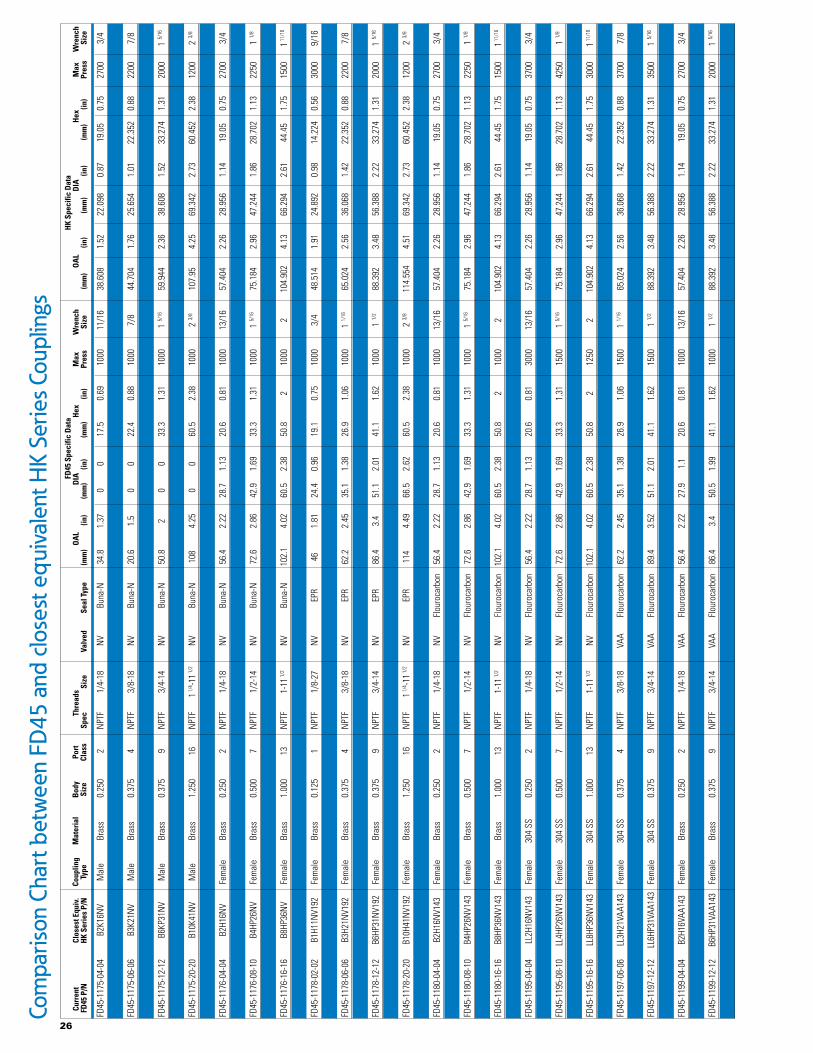
FD45
-117
5-04
-04
B2K1
6NV
Mal
e Br
ass
0.25
0 2
NPT
F 1/
4-18
N
V Bu
na-N
34
.8
1.37
0
0 17
.5
0.69
10
00
11/1
6 38
.608
1.
52
22.0
98
0.87
19
.05
0.75
27
00
3/4
FD45
-117
5-06
-06
B3K2
1NV
Mal
e Br
ass
0.37
5 4
NPT
F 3/
8-18
N
V Bu
na-N
20
.6
1.5
0 0
22.4
0.
88
1000
7/
8 44
.704
1.
76
25.6
54
1.01
22
.352
0.
88
2200
7/
8
FD45
-117
5-06
-06
B3K2
1NV
Mal
e Br
ass
0.37
5 4
NPT
F 3/
8-18
N
V Bu
na-N
20
.6
1.5
0 0
22.4
0.
88
1000
7/
8 44
.704
1.
76
25.6
54
1.01
22
.352
0.
88
2200
7/
8
FD45
-117
5-08
-10
B4KP
26N
V M
ale
Bras
s 0.
500
7 N
PTF
1/2-
14
NV
Buna
-N
44.7
1.
76
0 0
26.9
1.
06
1000
1 1
/16
51.5
62
2.03
33
.02
1.3
28.7
02
1.13
22
50
1 1/8
FD45
-117
5-12
-12
B6KP
31N
V M
ale
Bras
s 0.
375
9 N
PTF
3/4-
14
NV
Buna
-N
50.8
2
0 0
33.3
1.
31
1000
1 5
/16
59.9
44
2.36
38
.608
1.
52
33.2
74
1.31
20
00
1 5/1
6
FD45
-117
5-16
-16
B8KP
36N
V M
ale
Bras
s 1.
000
13
NPT
F 1-
11 1
/2
NV
Buna
-N
61.7
2.
43
0 0
41.1
1.
62
1000
1 1
/2
72.3
9 2.
85
47.7
52
1.88
41
.402
1.
63
1500
1 5
/8
FD45
-117
5-20
-20
B10K
41N
V M
ale
Bras
s 1.
250
16
NPT
F 1 1
/4-1
1 1/2
N
V Bu
na-N
10
8 4.
25
0 0
60.5
2.
38
1000
2 3
/8
107.
95
4.25
69
.342
2.
73
60.4
52
2.38
12
00
2 3/8
FD45
-117
6-02
-02
B1H1
1NV
Fem
ale
Bras
s 0.
125
1 N
PTF
1/8-
27
NV
Buna
-N
46
1.81
24
.4
0.96
19
.1
0.75
10
00
3/4
48.5
14
1.91
24
.892
0.
98
14.2
24
0.56
30
00
9/16
FD45
-117
6-04
-04
B2H1
6NV
Fem
ale
Bras
s 0.
250
2 N
PTF
1/4-
18
NV
Buna
-N
56.4
2.
22
28.7
1.
13
20.6
0.
81
1000
13
/16
57.4
04
2.26
28
.956
1.
14
19.0
5 0.
75
2700
3/
4
FD45
-117
6-06
-06
B3H2
1NV
Fem
ale
Bras
s 0.
375
4 N
PTF
3/8-
18
NV
Buna
-N
62.2
2.
45
35.1
1.
38
26.9
1.
06
1000
1 1
/16
65.0
24
2.56
36
.068
1.
42
22.3
52
0.88
22
00
7/8
FD45
-117
6-08
-10
B4HP
26N
V Fe
mal
e Br
ass
0.50
0 7
NPT
F 1/
2-14
N
V Bu
na-N
72
.6
2.86
42
.9
1.69
33
.3
1.31
10
00
1 5/1
6 75
.184
2.
96
47.2
44
1.86
28
.702
1.
13
2250
1 1
/8
FD45
-117
6-12
-12
B6HP
31N
V Fe
mal
e Br
ass
0.37
5 9
NPT
F 3/
4-14
N
V Bu
na-N
86
.4
3.4
51.1
2.
01
41.1
1.
62
1000
1 1
/2
88.3
92
3.48
56
.388
2.
22
33.2
74
1.31
20
00
1 5/1
6
FD45
-117
6-16
-16
B8HP
36N
V Fe
mal
e Br
ass
1.00
0 13
N
PTF
1-11
1/2
N
V Bu
na-N
10
2.1
4.02
60
.5
2.38
50
.8
2 10
00
2
10
4.90
2 4.
13
66.2
94
2.61
44
.45
1.75
15
00
1 11/
16
FD45
-117
6-20
-20
B10H
41N
V Fe
mal
e Br
ass
1.25
0 16
N
PTF
1 1/4
-11 1
/2
NV
Buna
-N
114
4.49
66
.5
2.62
60
.5
2.38
10
00
2 3/8
11
4.55
4 4.
51
69.3
42
2.73
60
.452
2.
38
1200
2 3
/8
FD45
-117
8-02
-02
B1H1
1NV1
92
Fem
ale
Bras
s 0.
125
1 N
PTF
1/8-
27
NV
EPR
46
1.81
24
.4
0.96
19
.1
0.75
10
00
3/4
48.5
14
1.91
24
.892
0.
98
14.2
24
0.56
30
00
9/16
FD45
-117
8-04
-04
B2H1
6NV1
92
Fem
ale
Bras
s 0.
250
2 N
PTF
1/4-
18
NV
EPR
56.4
2.
22
28.7
1.
13
20.6
0.
81
1000
13
/16
57.4
04
2.26
28
.956
1.
14
19.0
5 0.
75
2700
3/
4
FD45
-117
8-06
-06
B3H2
1NV1
92
Fem
ale
Bras
s 0.
375
4 N
PTF
3/8-
18
NV
EPR
62.2
2.
45
35.1
1.
38
26.9
1.
06
1000
1 1
/16
65.0
24
2.56
36
.068
1.
42
22.3
52
0.88
22
00
7/8
FD45
-117
8-08
-10
B4HP
26N
V192
Fe
mal
e Br
ass
0.50
0 7
NPT
F 1/
2-14
N
V EP
R 72
.6
2.86
42
.9
1.69
33
.3
1.31
10
00
1 5/1
6 75
.184
2.
96
47.2
44
1.86
28
.702
1.
13
2250
1 1
/8
FD45
-117
8-12
-12
B6HP
31N
V192
Fe
mal
e Br
ass
0.37
5 9
NPT
F 3/
4-14
N
V EP
R 86
.4
3.4
51.1
2.
01
41.1
1.
62
1000
1 1
/2
88.3
92
3.48
56
.388
2.
22
33.2
74
1.31
20
00
1 5/1
6
FD45
-117
8-16
-16
B8HP
36N
V192
Fe
mal
e Br
ass
1.00
0 13
N
PTF
1-11
1/2
N
V EP
R 10
2.1
4.02
60
.5
2.38
50
.8
2 10
00
2
10
4.90
2 4.
13
66.2
94
2.61
44
.45
1.75
15
00
1 11/
16
FD45
-117
8-20
-20
B10H
41N
V192
Fe
mal
e Br
ass
1.25
0 16
N
PTF
1 1/4
-11 1
/2
NV
EPR
114
4.49
66
.5
2.62
60
.5
2.38
10
00
2 3/8
11
4.55
4 4.
51
69.3
42
2.73
60
.452
2.
38
1200
2 3
/8
FD45
-118
0-02
-02
B1H1
1NV1
43
Fem
ale
Bras
s 0.
125
1 N
PTF
1/8-
27
NV
Flou
roca
rbon
46
1.
81
24.4
0.
96
19.1
0.
75
1000
3/
4 48
.514
1.
91
24.8
92
0.98
14
.224
0.
56
3000
9/
16
FD45
-118
0-04
-04
B2H1
6NV1
43
Fem
ale
Bras
s 0.
250
2 N
PTF
1/4-
18
NV
Flou
roca
rbon
56
.4
2.22
28
.7
1.13
20
.6
0.81
10
00
13/1
6 57
.404
2.
26
28.9
56
1.14
19
.05
0.75
27
00
3/4
FD45
-118
0-06
-06
B3H2
1NV1
43
Fem
ale
Bras
s 0.
375
4 N
PTF
3/8-
18
NV
Flou
roca
rbon
62
.2
2.45
35
.1
1.38
26
.9
1.06
10
00
1 1/1
6 65
.024
2.
56
36.0
68
1.42
22
.352
0.
88
2200
7/
8
FD45
-118
0-08
-10
B4HP
26N
V143
Fe
mal
e Br
ass
0.50
0 7
NPT
F 1/
2-14
N
V Fl
ouro
carb
on
72.6
2.
86
42.9
1.
69
33.3
1.
31
1000
1 5
/16
75.1
84
2.96
47
.244
1.
86
28.7
02
1.13
22
50
1 1/8
FD45
-118
0-12
-12
B6HP
31N
V143
Fe
mal
e Br
ass
0.37
5 9
NPT
F 3/
4-14
N
V Fl
ouro
carb
on
86.4
3.
4 51
.1
2.01
41
.1
1.62
10
00
1 1/2
88
.392
3.
48
56.3
88
2.22
33
.274
1.
31
2000
1 5
/16
FD45
-118
0-16
-16
B8HP
36N
V143
Fe
mal
e Br
ass
1.00
0 13
N
PTF
1-11
1/2
N
V Fl
ouro
carb
on
102.
1 4.
02
60.5
2.
38
50.8
2
1000
2
104.
902
4.13
66
.294
2.
61
44.4
5 1.
75
1500
1 1
1/16
FD45
-118
0-20
-20
B10H
41N
V143
Fe
mal
e Br
ass
1.25
0 16
N
PTF
1 1/4
-11 1
/2
NV
Flou
roca
rbon
11
4 4.
49
66.5
2.
62
60.5
2.
38
1000
2 3
/8
114.
554
4.51
69
.342
2.
73
60.4
52
2.38
12
00
2 3/8
FD45
-119
5-04
-04
LL2H
16N
V143
Fe
mal
e 30
4 SS
0.
250
2 N
PTF
1/4-
18
NV
Flou
roca
rbon
56
.4
2.22
28
.7
1.13
20
.6
0.81
30
00
13/1
6 57
.404
2.
26
28.9
56
1.14
19
.05
0.75
37
00
3/4
FD45
-119
5-06
-06
LL3H
21N
V143
Fe
mal
e 30
4 SS
0.
375
4 N
PTF
3/8-
18
NV
Flou
roca
rbon
62
.2
2.45
35
.1
1.38
26
.9
1.06
15
00
1 1/1
6 65
.024
2.
56
36.0
68
1.42
22
.352
0.
88
3700
7/
8
FD45
-119
5-08
-10
LL4H
P26N
V143
Fe
mal
e 30
4 SS
0.
500
7 N
PTF
1/2-
14
NV
Flou
roca
rbon
72
.6
2.86
42
.9
1.69
33
.3
1.31
15
00
1 5/1
6 75
.184
2.
96
47.2
44
1.86
28
.702
1.
13
4250
1 1
/8
FD45
-119
5-12
-12
LL6H
P31N
V143
Fe
mal
e 30
4 SS
0.
375
9 N
PTF
3/4-
14
NV
Flou
roca
rbon
89
.4
3.52
51
.1
2.01
41
.1
1.62
15
00
1 1/2
88
.392
3.
48
56.3
88
2.22
33
.274
1.
31
3500
1 5
/16
FD45
-119
5-16
-16
LL8H
P36N
V143
Fe
mal
e 30
4 SS
1.
000
13
NPT
F 1-
11 1
/2
NV
Flou
roca
rbon
10
2.1
4.02
60
.5
2.38
50
.8
2 12
50
2
10
4.90
2 4.
13
66.2
94
2.61
44
.45
1.75
30
00
1 11/
16
FD45
-119
7-04
-04
LL2H
16VA
A143
Fe
mal
e 30
4 SS
0.
250
2 N
PTF
1/4-
18
VAA
Flou
roca
rbon
56
.4
2.22
28
.7
1.13
20
.6
0.81
30
00
13/1
6 57
.404
2.
26
28.9
56
1.14
19
.05
0.75
37
00
3/4
FD45
-119
7-06
-06
LL3H
21VA
A143
Fe
mal
e 30
4 SS
0.
375
4 N
PTF
3/8-
18
VAA
Flou
roca
rbon
62
.2
2.45
35
.1
1.38
26
.9
1.06
15
00
1 1/1
6 65
.024
2.
56
36.0
68
1.42
22
.352
0.
88
3700
7/
8
FD45
-119
7-08
-10
LL4H
P26V
AA14
3 Fe
mal
e 30
4 SS
0.
500
7 N
PTF
1/2-
14
VAA
Flou
roca
rbon
72
.6
2.86
42
.9
1.69
33
.3
1.31
15
00
1 5/1
6 75
.184
2.
96
47.2
44
1.86
28
.702
1.
13
4250
1 1
/8
FD45
-119
7-12
-12
LL6H
P31V
AA14
3 Fe
mal
e 30
4 SS
0.
375
9 N
PTF
3/4-
14
VAA
Flou
roca
rbon
89
.4
3.52
51
.1
2.01
41
.1
1.62
15
00
1 1/2
88
.392
3.
48
56.3
88
2.22
33
.274
1.
31
3500
1 5
/16
FD45
-119
7-16
-16
LL8H
P36V
AA14
3 Fe
mal
e 30
4 SS
1.
000
13
NPT
F 1-
11 1
/2
VAA
Flou
roca
rbon
10
2.1
4.02
60
.5
2.38
50
.8
2 12
50
2
10
4.90
2 4.
13
66.2
94
2.61
44
.45
1.75
30
00
1 11/
16
FD45
-119
9-04
-04
B2H1
6VAA
143
Fem
ale
Bras
s 0.
250
2 N
PTF
1/4-
18
VAA
Flou
roca
rbon
56
.4
2.22
27
.9
1.1
20.6
0.
81
1000
13
/16
57.4
04
2.26
28
.956
1.
14
19.0
5 0.
75
2700
3/
4
FD45
-119
9-06
-06
B3H2
1VAA
143
Fem
ale
Bras
s 0.
375
4 N
PTF
3/8-
18
VAA
Flou
roca
rbon
62
.2
2.45
34
.5
1.36
26
.9
1.06
10
00
1 1/1
6 65
.024
2.
56
36.0
68
1.42
22
.352
0.
88
2200
7/
8
FD45
-119
9-12
-12
B6HP
31VA
A143
Fe
mal
e Br
ass
0.37
5 9
NPT
F 3/
4-14
VA
A Fl
ouro
carb
on
86.4
3.
4 50
.5
1.99
41
.1
1.62
10
00
1 1/2
88
.392
3.
48
56.3
88
2.22
33
.274
1.
31
2000
1 5
/16
FD45
-120
1-04
-04
B2K1
6VAA
M
ale
Bras
s 0.
250
2 N
PTF
1/4-
18
VAA
Buna
-N
38.1
1.
5 0
0 17
.5
0.69
10
00
11/1
6 38
.608
1.
52
22.0
98
0.87
19
.05
0.75
27
00
3/4
26
Com
paris
on C
hart
bet
wee
n FD
45 a
nd c
lose
st e
quiv
alen
t HK
Serie
s Cou
plin
gs
Th
read
s
Spec
Size
Valv
ed
Se
al T
ype
FD45
Spe
cific
Dat
a
OA
L D
IA
Hex
M
ax
Wre
nch
(m
m)
(in)
(mm
) (in
) (m
m)
(in)
Pres
s Si
ze
HK
Spec
ific
Dat
a
OA
L D
IA
Hex
M
ax
Wre
nch
(m
m)
(in)
(mm
) (in
) (m
m)
(in)
Pres
s Si
ze
Curr
ent
Cl
oses
t Equ
iv.
FD
45 P
/N
H
K Se
ries
P/N
Co
uplin
g M
ater
ial
Bod
y Po
rt
Type
Size
Cl
ass
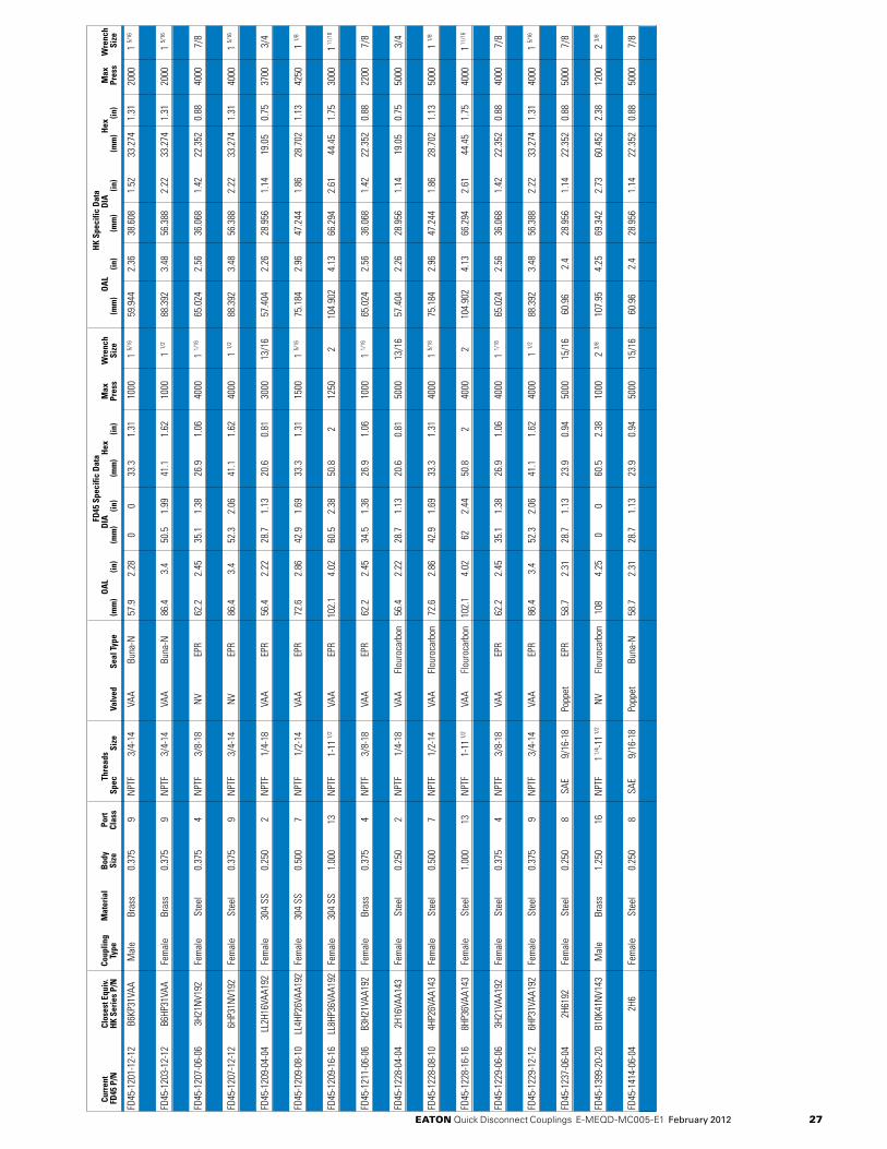
FD45
-120
1-12
-12
B6KP
31VA
A M
ale
Bras
s 0.
375
9 N
PTF
3/4-
14
VAA
Buna
-N
57.9
2.
28
0 0
33.3
1.
31
1000
1 5
/16
59.9
44
2.36
38
.608
1.
52
33.2
74
1.31
20
00
1 5/1
6
FD45
-120
3-04
-04
B2H1
6VAA
Fe
mal
e Br
ass
0.25
0 2
NPT
F 1/
4-18
VA
A Bu
na-N
56
.4
2.22
27
.9
1.1
20.6
0.
81
1000
13
/16
57.4
04
2.26
28
.956
1.
14
19.0
5 0.
75
2700
3/
4
FD45
-120
3-12
-12
B6HP
31VA
A Fe
mal
e Br
ass
0.37
5 9
NPT
F 3/
4-14
VA
A Bu
na-N
86
.4
3.4
50.5
1.
99
41.1
1.
62
1000
1 1
/2
88.3
92
3.48
56
.388
2.
22
33.2
74
1.31
20
00
1 5/1
6
FD45
-120
7-04
-04
2H16
NV1
92
Fem
ale
Stee
l 0.
250
2 N
PTF
1/4-
18
NV
EPR
56.4
2.
22
28.7
1.
13
20.6
0.
81
5000
13
/16
57.4
04
2.26
28
.956
1.
14
19.0
5 0.
75
5000
3/
4
FD45
-120
7-06
-06
3H21
NV1
92
Fem
ale
Stee
l 0.
375
4 N
PTF
3/8-
18
NV
EPR
62.2
2.
45
35.1
1.
38
26.9
1.
06
4000
1 1
/16
65.0
24
2.56
36
.068
1.
42
22.3
52
0.88
40
00
7/8
FD45
-120
7-08
-10
4HP2
6NV1
92
Fem
ale
Stee
l 0.
500
7 N
PTF
1/2-
14
NV
EPR
72.6
2.
86
42.9
1.
69
33.3
1.
31
4000
1 5
/16
75.1
84
2.96
47
.244
1.
86
28.7
02
1.13
50
00
1 1/8
FD45
-120
7-12
-12
6HP3
1NV1
92
Fem
ale
Stee
l 0.
375
9 N
PTF
3/4-
14
NV
EPR
86.4
3.
4 52
.3
2.06
41
.1
1.62
40
00
1 1/2
88
.392
3.
48
56.3
88
2.22
33
.274
1.
31
4000
1 5
/16
FD45
-120
7-16
-16
8HP3
6NV1
92
Fem
ale
Stee
l 1.
000
13
NPT
F 1-
11 1
/2
NV
EPR
102.
1 4.
02
62
2.44
50
.8
2 40
00
2
10
4.90
2 4.
13
66.2
94
2.61
44
.45
1.75
40
00
1 11/
16
FD45
-120
9-04
-04
LL2H
16VA
A192
Fe
mal
e 30
4 SS
0.
250
2 N
PTF
1/4-
18
VAA
EPR
56.4
2.
22
28.7
1.
13
20.6
0.
81
3000
13
/16
57.4
04
2.26
28
.956
1.
14
19.0
5 0.
75
3700
3/
4
FD45
-120
9-06
-06
LL3H
21VA
A192
Fe
mal
e 30
4 SS
0.
375
4 N
PTF
3/8-
18
VAA
EPR
62.2
2.
45
35.1
1.
38
26.9
1.
06
1500
1 1
/16
65.0
24
2.56
36
.068
1.
42
22.3
52
0.88
37
00
7/8
FD45
-120
9-08
-10
LL4H
P26V
AA19
2 Fe
mal
e 30
4 SS
0.
500
7 N
PTF
1/2-
14
VAA
EPR
72.6
2.
86
42.9
1.
69
33.3
1.
31
1500
1 5
/16
75.1
84
2.96
47
.244
1.
86
28.7
02
1.13
42
50
1 1/8
FD45
-120
9-12
-12
LL6H
P31V
AA19
2 Fe
mal
e 30
4 SS
0.
375
9 N
PTF
3/4-
14
VAA
EPR
89.4
3.
52
51.1
2.
01
41.1
1.
62
1500
1 1
/2
88.3
92
3.48
56
.388
2.
22
33.2
74
1.31
35
00
1 5/1
6
FD45
-120
9-16
-16
LL8H
P36V
AA19
2 Fe
mal
e 30
4 SS
1.
000
13
NPT
F 1-
11 1
/2
VAA
EPR
102.
1 4.
02
60.5
2.
38
50.8
2
1250
2
104.
902
4.13
66
.294
2.
61
44.4
5 1.
75
3000
1 1
1/16
FD45
-121
1-04
-04
B2H1
6VAA
192
Fem
ale
Bras
s 0.
250
2 N
PTF
1/4-
18
VAA
EPR
56.4
2.
22
27.9
1.
1 20
.6
0.81
10
00
13/1
6 57
.404
2.
26
28.9
56
1.14
19
.05
0.75
27
00
3/4
FD45
-121
1-06
-06
B3H2
1VAA
192
Fem
ale
Bras
s 0.
375
4 N
PTF
3/8-
18
VAA
EPR
62.2
2.
45
34.5
1.
36
26.9
1.
06
1000
1 1
/16
65.0
24
2.56
36
.068
1.
42
22.3
52
0.88
22
00
7/8
FD45
-121
1-12
-12
B6HP
31VA
A192
Fe
mal
e Br
ass
0.37
5 9
NPT
F 3/
4-14
VA
A EP
R 86
.4
3.4
50.5
1.
99
41.1
1.
62
1000
1 1
/2
88.3
92
3.48
56
.388
2.
22
33.2
74
1.31
20
00
1 5/1
6
FD45
-122
8-04
-04
2H16
VAA1
43
Fem
ale
Stee
l 0.
250
2 N
PTF
1/4-
18
VAA
Flou
roca
rbon
56
.4
2.22
28
.7
1.13
20
.6
0.81
50
00
13/1
6 57
.404
2.
26
28.9
56
1.14
19
.05
0.75
50
00
3/4
FD45
-122
8-06
-06
3H21
VAA1
43
Fem
ale
Stee
l 0.
375
4 N
PTF
3/8-
18
VAA
Flou
roca
rbon
62
.2
2.45
35
.1
1.38
26
.9
1.06
40
00
1 1/1
6 65
.024
2.
56
36.0
68
1.42
22
.352
0.
88
4000
7/
8
FD45
-122
8-08
-10
4HP2
6VAA
143
Fem
ale
Stee
l 0.
500
7 N
PTF
1/2-
14
VAA
Flou
roca
rbon
72
.6
2.86
42
.9
1.69
33
.3
1.31
40
00
1 5/1
6 75
.184
2.
96
47.2
44
1.86
28
.702
1.
13
5000
1 1
/8
FD45
-122
8-12
-12
6HP3
1VAA
143
Fem
ale
Stee
l 0.
375
9 N
PTF
3/4-
14
VAA
Flou
roca
rbon
86
.4
3.4
52.3
2.
06
41.1
1.
62
4000
1 1
/2
88.3
92
3.48
56
.388
2.
22
33.2
74
1.31
40
00
1 5/1
6
FD45
-122
8-16
-16
8HP3
6VAA
143
Fem
ale
Stee
l 1.
000
13
NPT
F 1-
11 1
/2
VAA
Flou
roca
rbon
10
2.1
4.02
62
2.
44
50.8
2
4000
2
104.
902
4.13
66
.294
2.
61
44.4
5 1.
75
4000
1 1
1/16
FD45
-122
9-04
-04
2H16
VAA1
92
Fem
ale
Stee
l 0.
250
2 N
PTF
1/4-
18
VAA
EPR
56.4
2.
22
28.7
1.
13
20.6
0.
81
5000
13
/16
57.4
04
2.26
28
.956
1.
14
19.0
5 0.
75
5000
3/
4
FD45
-122
9-06
-06
3H21
VAA1
92
Fem
ale
Stee
l 0.
375
4 N
PTF
3/8-
18
VAA
EPR
62.2
2.
45
35.1
1.
38
26.9
1.
06
4000
1 1
/16
65.0
24
2.56
36
.068
1.
42
22.3
52
0.88
40
00
7/8
FD45
-122
9-08
-10
4HP2
6VAA
192
Fem
ale
Stee
l 0.
500
7 N
PTF
1/2-
14
VAA
EPR
72.6
2.
86
42.9
1.
69
33.3
1.
31
4000
1 5
/16
75.1
84
2.96
47
.244
1.
86
28.7
02
1.13
50
00
1 1/8
FD45
-122
9-12
-12
6HP3
1VAA
192
Fem
ale
Stee
l 0.
375
9 N
PTF
3/4-
14
VAA
EPR
86.4
3.
4 52
.3
2.06
41
.1
1.62
40
00
1 1/2
88
.392
3.
48
56.3
88
2.22
33
.274
1.
31
4000
1 5
/16
FD45
-122
9-16
-16
8HP3
6VAA
192
Fem
ale
Stee
l 1.
000
13
NPT
F 1-
11 1
/2
VAA
EPR
102.
1 4.
02
62
2.44
50
.8
2 40
00
2
10
4.90
2 4.
13
66.2
94
2.61
44
.45
1.75
40
00
1 11/
16
FD45
-123
7-06
-04
2H61
92
Fem
ale
Stee
l 0.
250
8 SA
E 9/
16-1
8 Po
ppet
EP
R 58
.7
2.31
28
.7
1.13
23
.9
0.94
50
00
15/1
6 60
.96
2.4
28.9
56
1.14
22
.352
0.
88
5000
7/
8
FD45
-123
8-06
-04
2K61
92
Mal
e St
eel
0.25
0 8
SAE
9/16
-18
Popp
et
EPR
42.7
1.
68
0 0
20.6
0.
81
5000
13
/16
42.1
64
1.66
25
.654
1.
01
22.3
52
0.88
50
00
7/8
FD45
-139
9-20
-20
B10K
41N
V143
M
ale
Bras
s 1.
250
16
NPT
F 1 1
/4-1
1 1/2
N
V Fl
ouro
carb
on
108
4.25
0
0 60
.5
2.38
10
00
2 3/8
10
7.95
4.
25
69.3
42
2.73
60
.452
2.
38
1200
2 3
/8
FD45
-140
0-20
-20
B10K
41N
V192
M
ale
Bras
s 1.
250
16
NPT
F 1 1
/4-1
1 1/2
N
V EP
R 10
8 4.
25
0 0
60.5
2.
38
1000
2 3
/8
107.
95
4.25
69
.342
2.
73
60.4
52
2.38
12
00
2 3/8
FD45
-141
4-06
-04
2H6
Fem
ale
Stee
l 0.
250
8 SA
E 9/
16-1
8 Po
ppet
Bu
na-N
58
.7
2.31
28
.7
1.13
23
.9
0.94
50
00
15/1
6 60
.96
2.4
28.9
56
1.14
22
.352
0.
88
5000
7/
8
FD45
-141
5-06
-04
2K6
Mal
e St
eel
0.25
0 8
SAE
9/16
-18
Popp
et
Buna
-N
42.7
1.
68
0 0
20.6
0.
81
5000
13
/16
42.1
64
1.66
25
.654
1.
01
22.3
52
0.88
50
00
7/8
eaton Quick Disconnect Couplings E-MEQD-MC005-E1 February 2012 27
Thre
ads
Sp
ec
Si
zeVa
lved
Seal
Typ
e
FD45
Spe
cific
Dat
a
OA
L D
IA
Hex
M
ax
Wre
nch
(m
m)
(in)
(mm
) (in
) (m
m)
(in)
Pres
s Si
ze
HK
Spec
ific
Dat
a
OA
L D
IA
Hex
M
ax
Wre
nch
(m
m)
(in)
(mm
) (in
) (m
m)
(in)
Pres
s Si
ze
Curr
ent
Cl
oses
t Equ
iv.
FD
45 P
/N
H
K Se
ries
P/N
Co
uplin
g M
ater
ial
Bod
y Po
rt
Type
Size
Cl
ass

© 2012 Eaton CorporationAll Rights Reserved Printed in USADocument No. E-MEQD-MC005-E1February 2012
Eaton Hydraulics Group USA1000 W. Bagley RoadBerea, OH 44017-0805USATel: 440-826-1115Fax: 440-826-1105www.eaton.com/hydraulics
Eaton Hydraulics Group USA14615 Lone Oak RoadEden Prairie, MN 55344USATel: 952-937-9800Fax: 952-294-7722www.eaton.com/hydraulics
EatonHydraulics Group EuropeRoute de la Longeraie 71110 MorgesSwitzerlandTel: +41 (0) 21 811 4600Fax: +41 (0) 21 811 4601
EatonHydraulics Group Asia PacificEaton Building4th Floor, No. 3 Lane 280 Linhong Rd. Changning DistrictShanghai 200335ChinaTel: (+86 21) 5200 0099Fax: (+86 21) 5200 0400