Embed Size (px)
Citation preview
Low Power Radio Solutions Ltd
Station Lane
Witney OXON
OX28 4BH
http://www.lprs.co.uk
eRA900TRS (Rev 1.0) Page 1 of 16
easyRadio Advanced Datasheet
Module(s) Included
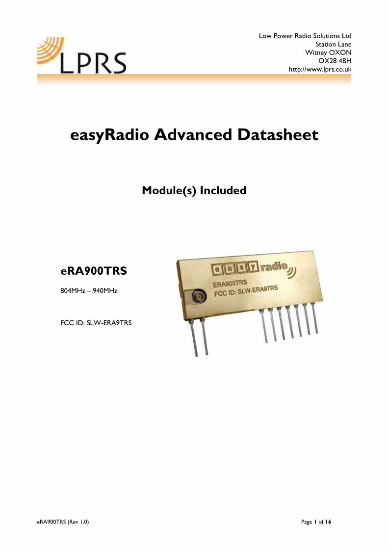
eRA900TRS
804MHz – 940MHz
FCC ID: SLW-ERA9TRS

eRA900TRS (Rev 1.0) Page 2 of 16
Table of Contents
FCC Warning Statement: ...........................................3
Antennas Approved for use with eRA900TRS .....3
Introduction to easyRadio..........................................4
Advanced ........................................................................4
Features: ................................................................4
ERA900TRS Transceiver Description .....................5
easyRadio Transceiver ................................................5
Block Diagram......................................................5
Physical Dimensions ...........................................5
Pin Description .............................................................6
Checklist .........................................................................6
Application & Operation of eRAx00TRS Transceivers ..................................................................7
Typical System Block Diagram ..................................7
Absolute Maximum Ratings .......................................8
ERA900TRS Channel Frequencies vs Bandwidth Settings ............................................................................9
easyRadio Configuration Command Set .............. 10
RS232 Communication Settings ................... 10
RF Channel Settings ......................................... 10
RSSI ............................................................................... 13
PCB Layout ................................................................. 14
Power Supply .............................................................. 14
Antennas ...................................................................... 14
Product Order Codes .............................................. 15
easy-Radio Advanced Module Firmware Version ....................................................................................... 15
Changes to this Document ..................................... 15
Document History .................................................... 15
Copyright .................................................................... 15
Disclaimer and Terms and Conditions of Use ... 15
Contact Information ................................................. 16

eRA900TRS (Rev 1.0) Page 3 of 16
FCC Warning Statement:
This device complies with Part 15 of the FCC Rules.
Operation is subject to the following two conditions:
(1) This device may not cause harmful interference, and
(2) This device must accept any interference received, including interference that may cause unde-
sired operation.
This equipment complies with FCC radiation exposure limits set forth for an uncontrolled envron-
ment. End users must follow the specific operating instructions for satisfying RF exposure compli-
ance. This transmitter must not be co-located or operated in conjunction with any other antenna
or transmitter. This device should not be used with antennas other than those specified below or
those of less or equal gain to the maximum gain used in the table below.
Changes or modifications not expressly approved by the party responsible for compliance could
void the user’s authority to operate the equipment.
Antennas Approved for use with eRA900TRS
Antennas must be used in conjunction with the specified UFL cable (below) or equivalent:
LPRS Part Number: ARW-CAB-SMA-UFL-10
Part Number Gain Supplier Notes
ANT-900MS 3dBi LPRS
ANT-WP915SMA-Y 2.5dBi LPRS
ANT-RP915SMA-Y 2dBi LPRS
eRA900TRS (Rev 1.0) Page 4 of 16
Introduction to easyRadio
Advanced
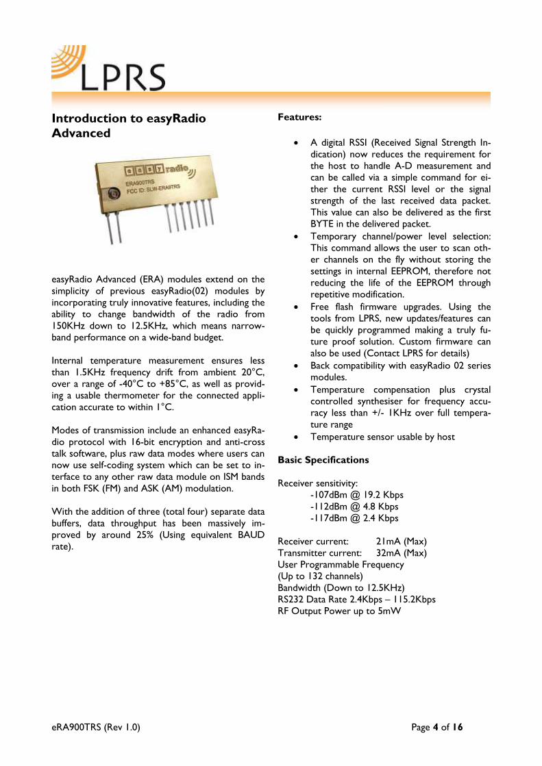
easyRadio Advanced (ERA) modules extend on the
simplicity of previous easyRadio(02) modules by
incorporating truly innovative features, including the
ability to change bandwidth of the radio from
150KHz down to 12.5KHz, which means narrow-
band performance on a wide-band budget.
Internal temperature measurement ensures less
than 1.5KHz frequency drift from ambient 20°C,
over a range of -40°C to +85°C, as well as provid-
ing a usable thermometer for the connected appli-
cation accurate to within 1°C.
Modes of transmission include an enhanced easyRa-
dio protocol with 16-bit encryption and anti-cross
talk software, plus raw data modes where users can
now use self-coding system which can be set to in-
terface to any other raw data module on ISM bands
in both FSK (FM) and ASK (AM) modulation.
With the addition of three (total four) separate data
buffers, data throughput has been massively im-
proved by around 25% (Using equivalent BAUD
rate).
Features:
A digital RSSI (Received Signal Strength In-
dication) now reduces the requirement for
the host to handle A-D measurement and
can be called via a simple command for ei-
ther the current RSSI level or the signal
strength of the last received data packet.
This value can also be delivered as the first
BYTE in the delivered packet.
Temporary channel/power level selection:
This command allows the user to scan oth-
er channels on the fly without storing the
settings in internal EEPROM, therefore not
reducing the life of the EEPROM through
repetitive modification.
Free flash firmware upgrades. Using the
tools from LPRS, new updates/features can
be quickly programmed making a truly fu-
ture proof solution. Custom firmware can
also be used (Contact LPRS for details)
Back compatibility with easyRadio 02 series
modules.
Temperature compensation plus crystal
controlled synthesiser for frequency accu-
racy less than +/- 1KHz over full tempera-
ture range
Temperature sensor usable by host
Basic Specifications
Receiver sensitivity:
-107dBm @ 19.2 Kbps
-112dBm @ 4.8 Kbps
-117dBm @ 2.4 Kbps
Receiver current: 21mA (Max)
Transmitter current: 32mA (Max)
User Programmable Frequency
(Up to 132 channels)
Bandwidth (Down to 12.5KHz)
RS232 Data Rate 2.4Kbps – 115.2Kbps
RF Output Power up to 5mW
eRA900TRS (Rev 1.1) Page 5 of 16
ERA900TRS Transceiver Description
The easyRadio Transceiver is a complete sub-system that combines a high performance very low power RF
transceiver, a microcontroller and a voltage regulator.
The Serial Data Input and Serial Data Output operate at the standard 19,200 Baud and the two handshake
lines provide optional flow control to and from the host. The easyRadio Transceiver can accept and trans-
mit up to 180 bytes of data, which it buffers internally before transmitting in an efficient over-air code for-
mat.
Any other easyRadio Transceiver within range and on the same channel that ‘hears’ the transmission will
decode the message and place the recovered data within a receive buffer that can then be downloaded to
the receiving host for processing and interpretation. Radio transmission and reception is bi-directional (half
duplex) i.e. transmit OR receive but not simultaneously.
Increased internal buffers however, allow the user to upload while a download is in progress giving an ap-
pearance of fully duplex data flow.
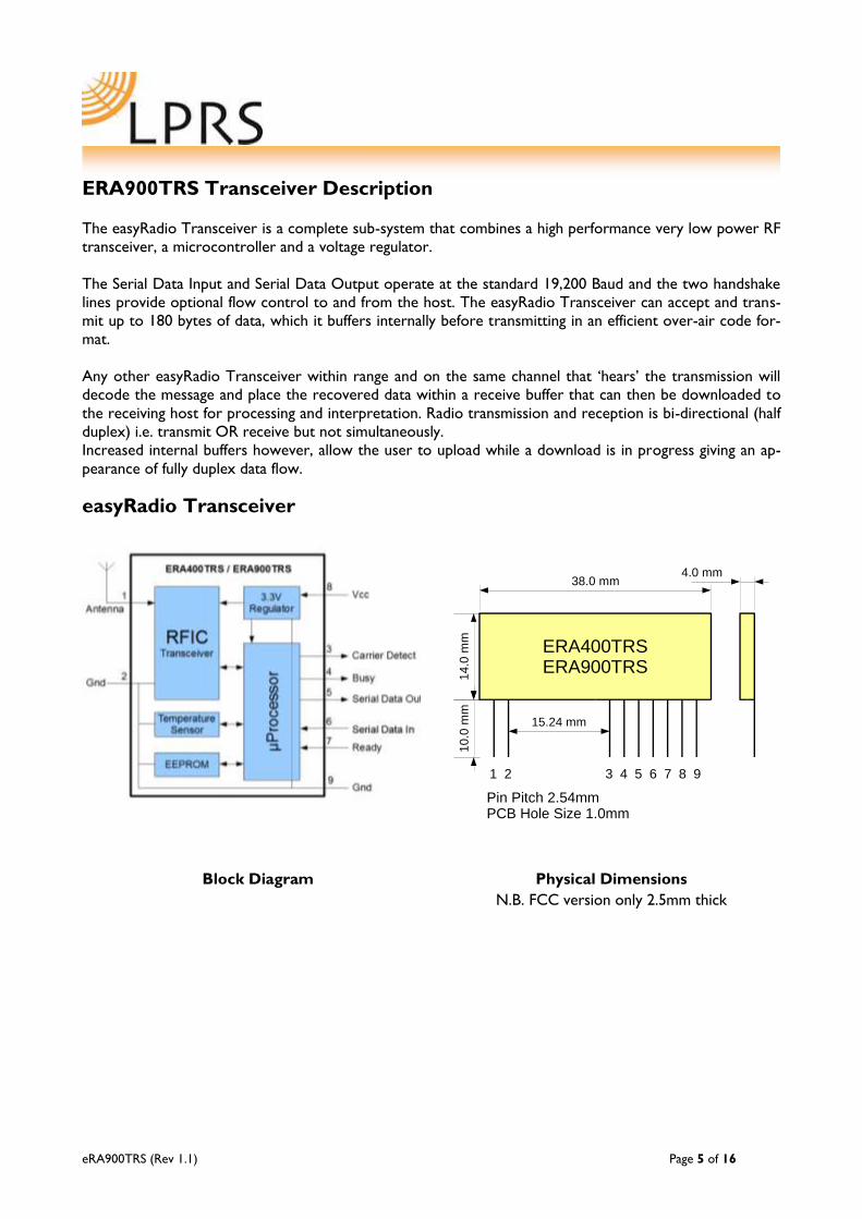
easyRadio Transceiver
Block Diagram Physical Dimensions
N.B. FCC version only 2.5mm thick
ERA400TRSERA900TRS
Pin Pitch 2.54mmPCB Hole Size 1.0mm
1 2 3 4 5 6 7 8 9
38.0 mm
14
.0 m
m1
0.0
mm
15.24 mm
4.0 mm
eRA900TRS (Rev 1.1) Page 6 of 16
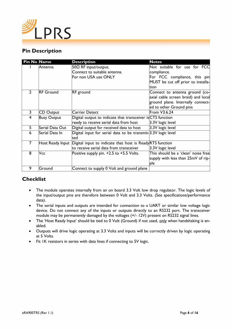
Pin Description
Pin No Name Description Notes
1 Antenna 50Ω RF input/output.
Connect to suitable antenna.
For non USA use ONLY
Not suitable for use for FCC
compliance.
For FCC compliance, this pin
MUST be cut off prior to installa-
tion
2 RF Ground RF ground Connect to antenna ground (co-
axial cable screen braid) and local
ground plane. Internally connect-
ed to other Ground pins
3 CD Output Carrier Detect From V3.6.24
4 Busy Output Digital output to indicate that transceiver is
ready to receive serial data from host
CTS function
3.3V logic level
5 Serial Data Out Digital output for received data to host 3.3V logic level
6 Serial Data In Digital input for serial data to be transmit-
ted
3.3V logic level
7 Host Ready Input Digital input to indicate that host is Ready
to receive serial data from transceiver
RTS function
3.3V logic level
8 Vcc Positive supply pin. +2.5 to +5.5 Volts. This should be a ‘clean’ noise free
supply with less than 25mV of rip-
ple
9 Ground Connect to supply 0 Volt and ground plane
Checklist
The module operates internally from an on board 3.3 Volt low drop regulator. The logic levels of
the input/output pins are therefore between 0 Volt and 3.3 Volts. (See specifications/performance
data).
The serial inputs and outputs are intended for connection to a UART or similar low voltage logic
device. Do not connect any of the inputs or outputs directly to an RS232 port. The transceiver
module may be permanently damaged by the voltages (+/- 12V) present on RS232 signal lines.
The ‘Host Ready Input’ should be tied to 0 Volt (Ground) if not used, only when handshaking is en-
abled.
Outputs will drive logic operating at 3.3 Volts and inputs will be correctly driven by logic operating
at 5 Volts.
Fit 1K resistors in series with data lines if connecting to 5V logic.

eRA900TRS (Rev 1.1) Page 7 of 16
Application & Operation of eRA900TRS Transceivers
The diagram below shows a typical system block diagram comprising hosts (user’s application) connected
to easyRadio Transceivers. The hosts (A & B) will be monitoring (collecting data) and/or controlling (send-
ing data) to some real world application.
Easy-Radio
Transceiver
(A)
Host
(A)
Serial Data Input
Serial Data Output
Host Ready
Busy
Easy-Radio
Transceiver
(B)
Host
(B)
Serial Data Input
Serial Data Output
Host Ready
Busy
RF Link
Typical System Block Diagram
The hosts provide serial data input and output lines and two ‘handshaking’ lines that control the flow of
data to and from the easyRadio transceivers. The ‘Busy’ output line, when active, indicates that the trans-
ceiver is undertaking an internal task and is not ready to receive serial data. The ‘Host Ready’ input is used
to indicate that the host is ready to receive the data held in the buffer of the easyRadio Transceiver.
The host should check before sending data that the ‘Busy’ line is not high, as this would indicate that the
transceiver is unable to reliably receive further data. It should also pull the ‘Host Ready’ line low and check
that no data appears on the Serial Data Output line.
The busy output is active all the time regardless of handshaking setting. The host ready is enabled by the
handshaking setting.
eRA900TRS (Rev 1.1) Page 8 of 16
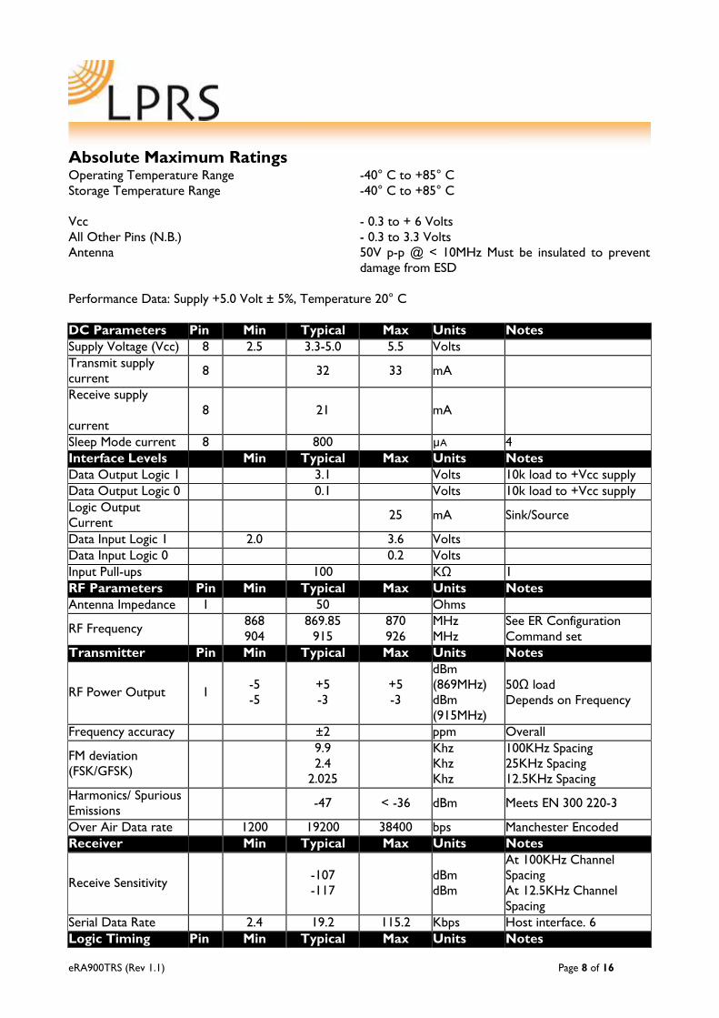
Absolute Maximum Ratings Operating Temperature Range -40° C to +85° C
Storage Temperature Range -40° C to +85° C
Vcc - 0.3 to + 6 Volts
All Other Pins (N.B.) - 0.3 to 3.3 Volts
Antenna 50V p-p @ < 10MHz Must be insulated to prevent
damage from ESD
Performance Data: Supply +5.0 Volt ± 5%, Temperature 20° C
DC Parameters Pin Min Typical Max Units Notes
Supply Voltage (Vcc) 8 2.5 3.3-5.0 5.5 Volts
Transmit supply
current 8 32 33 mA
Receive supply
current
8 21 mA
Sleep Mode current 8 800 µA 4
Interface Levels Min Typical Max Units Notes
Data Output Logic 1 3.1 Volts 10k load to +Vcc supply
Data Output Logic 0 0.1 Volts 10k load to +Vcc supply
Logic Output
Current 25 mA Sink/Source
Data Input Logic 1 2.0 3.6 Volts
Data Input Logic 0 0.2 Volts
Input Pull-ups 100 KΩ 1
RF Parameters Pin Min Typical Max Units Notes
Antenna Impedance 1 50 Ohms
RF Frequency 868
904
869.85
915
870
926
MHz
MHz
See ER Configuration
Command set
Transmitter Pin Min Typical Max Units Notes
RF Power Output 1 -5
-5
+5
-3
+5
-3
dBm
(869MHz)
dBm
(915MHz)
50Ω load
Depends on Frequency
Frequency accuracy ±2 ppm Overall
FM deviation
(FSK/GFSK)
9.9
2.4
2.025
Khz
Khz
Khz
100KHz Spacing
25KHz Spacing
12.5KHz Spacing
Harmonics/ Spurious
Emissions -47 < -36 dBm Meets EN 300 220-3
Over Air Data rate 1200 19200 38400 bps Manchester Encoded
Receiver Pin Min Typical Max Units Notes
Receive Sensitivity -107
-117
dBm
dBm
At 100KHz Channel
Spacing
At 12.5KHz Channel
Spacing
Serial Data Rate 2.4 19.2 115.2 Kbps Host interface. 6
Logic Timing Pin Min Typical Max Units Notes

eRA900TRS (Rev 1.1) Page 9 of 16
Initial Power Up Time 5 75 mS 2,3
Mechanical
Size 38 x 14 x 2.75 mm
Pin Pitch 2.54 mm (Standard 0.1 Inches)
Weight 3.5 grams
Notes:
The ‘Host Ready Input’ and the ‘Serial Data Input’ have ‘weak’ internal pull-ups enabled.
When power is first applied to the module the processor retrieves ‘calibration’ data for the RF sec-
tion that compensates for temperature and power supply voltage variations. The transceiver will
then be ready to receive (default) or transmit. It would normally be left in this powered state ready
to receive data.
During power up the Busy Output line goes high and then goes low when ready.
Applies to RAW data mode of transceiver when in idle state.
ERA900TRS Channel Frequencies vs Bandwidth Settings
Each channel frequency is calculated relative to the channel number, the channel width, and the start fre-
quency of the channel. Three commands control the settings of each of these parameters:
Channel command: ER_CMD#Cn - Where n is channel number (See command table)
Bandwidth Command: ER_CMD#Bn - Where n is the Channel spacing
Band Plan Command: ER_CMD#bn - Where n is the START frequency of the band plan being used
The centre frequency of each channel is calculated using the formula:
Centre Frequency
Where b = band plan start frequency
c = channel number
s = channel spacing

eRA900TRS (Rev 1.1) Page 10 of 16
easyRadio Configuration Command Set
The programming software sends ‘Text Commands’ to the modules and this action can be performed by
terminal software or the host’s microcontroller using the following list of commands:
RS232 Communication Settings
Command
ER_CMD#U1 2400
ER_CMD#U2 4800
ER_CMD#U3 9600
ER_CMD#U4 19200
ER_CMD#U5 38400
ER_CMD#U6 31250
ER_CMD#U7 76800
ER_CMD#U8 115200
ER_CMD#U? Get UART Value
The module replies echos with the UART value.
E.g: ER_CMD#U2
No ACK is required.
ER_CMD#A70 Parity Disable Disabled by default
When enabled data = 1 Start, 8 Data, 1 Parity, 1 Stop
ER_CMD#A71 Even Parity
ER_CMD#A72 Odd Parity
ER_CMD#A41 Fast ACK Enable Off Off
(Upper case i)
See notes on “FAST ACK”
below.
ER_CMD#A40 Fast ACK Disable
CE 869MHz
ER900
FCC
ER_CMD#P0~9 RF Power
Output
P0
P1
P2
P3
P4
P5
P6
P7
P8
P9
TRS
-1
0
1
2
3
4
5
6
6.5
7
TRS
-10
-4
0
2
3
4
5
6
6.5
7
dBm
dBm (FCC default)
dBm
dBm
dBm
dBm
dBm
dBm
dBm
dBm
ER_CMD#p0~9 Temporary RF
Power adjustment.
Lowercase ‘p’ allows power adjustment
without modifying the value for a Power
reset.
ER_CMD#P? Get Power Value
The module replies with the power value.
E.g: ER_CMD#P9
No ACK is required
RF Channel Settings
ER_CMD#Cx Where x = Channel E.g: Channel 5:

eRA900TRS (Rev 1.1) Page 11 of 16
Number in Decimal ER_CMD#C5 or
ER_CMD#C05 or
ER_CMD#C005
Uppercase 'C' stores settings in EEPROM
ER_CMD#cx As Upper case C Lowercase 'c' does not store in EEPROM
ER_CMD#C? Get Channel Value The module replies echoes with the cur-
rent channel.
E.g: ER_CMD#C9
No ACK is required.
Bandwidth
ER_CMD#Bx X = 0
1
2
3
6
12.5KHz
25KHz
50KHz
100KHz
150KHz
2400bps
4800bps
9600bps
19200bps
02 Compatibility
After this command, the
Channel number will set
to Channel 0.
Band Plan ERA900
ER_CMD#bx Default = 0
1
2
3
869.7MHz
902MHz
863MHz
This setting chooses the
start frequency of Chan-
nel 0
Miscellaneous
ER_CMD#R0 Reset module (POR) Power reset
ER_CMD#A00 DCS OFF (default) Used for 02 compatibility ONLY
See 02 Series documentation ER_CMD#A01 DCS ON
ER_CMD#A10 Encryption OFF (de-
fault)
Encryption algorithm is created and owned solely by LPRS. It
uses a 16-bit seed that can be set by the developer.
ER_CMD#A11 Encryption ON
ER_CMD#A20/21 CRC16 Off/On
On = default
The CRC16 routines are more efficient and secure than the old
CRC8. For new applications it is recommended.
All new Bandwidth settings use CRC16. This setting only applies
to 02 compatibility mode.
ER_CMD#A30/31 Repeater Off/On Not yet implemented
ER_CMD#A40/41 Fast ACK Off/On
ER_CMD#A50/51 Handshaking Off/On
ER_CMD#A70
ER_CMD#A71
ER_CMD#A72
Parity Disable
Parity Even
Parity Odd
Not yet implemented
ER_CMD#a00/01 RSSI In Packet
a00 = Off; a01 = On
When enabled each packet is preceded by the 8 bit RSSI value
of the received packet
ER_CMD#a1pxx Programmable
Carrier Detect
p = polarity: 0 = rest at 0 (1 when carrier detect)
1 = idle high, (0 when carrier detect)
xx = RSSI value in ASCII HEX
To disable, set xx = FF
Choose RSSI values in conjunction with RSSI graphs later in this
document
Test Modes
ER_CMD#T0 Upper FSK Carrier Test Mode 0
ER_CMD#T1 Modulated Carrier Test Mode 1
With temperature compensation
ER_CMD#T2 Lower FSK Carrier Test Mode 2
ER_CMD#T3 Get Firmware Revi- Returns Firmware string

eRA900TRS (Rev 1.1) Page 12 of 16
sion E.g: ERA400TRS V3.6.23
ER_CMD#T4 RAW Data Test Out of CTS pin
ER_CMD#T5 Modulated Carrier Without Temperature compensation
ER_CMD#T7 Temperature Sensor Reply example:
-15'C or 23.7'C
ER_CMD#T8 Last Packet RSSI Returns the HEX value of the RSSI register measured on the
last valid packet
ER_CMD#T9 Current RSSI Live RSSI Value
To send commands do the following:
Send Command from host: e.g. ER_CMD#U5 (Set UART BAUD to 38400)
Wait for echo of command from module. e.g. ER_CMD#U5 Send the ASCII string from the host: ACK
The commands should be sent exactly as shown (case sensitive) with no spaces between characters. The ACK com-
mand is sent as three ASCII characters, ACK in sequence. ‘A’’C’’K’ .

eRA900TRS (Rev 1.1) Page 13 of 16
RSSI
The transceiver has a built in RSSI (Received Signal Strength Indicator) that provides a digital value relating
to the power at the input. This value can be read back using the ER command “ER_CMD#T8” or can be
set to deliver the value as the first byte of each packet.
This value will be different, depending on the bandwidth currently in use. The graph below explains how to
interpret the values:
RSSI Levels (804MHz – 940MHz)

eRA900TRS (Rev 1.1) Page 14 of 16
PCB Layout
The Ground (0 Volt) pins of the receiver should be connected to a substantial ground plane (large area of
PCB copper) connected to 0 Volt. It is suggested that a double sided PCB be used with one layer being the
ground plane.
Power Supply
The supply used to power the receiver should be ‘clean’ and free from ripple and noise (<20mV p-p total).
It is suggested that 100nF ceramic capacitors be used to de-couple the supply close to the power pins of
the receiver. The use of ‘switch mode’ power supplies should be avoided as they can generate both con-
ducted and radiated high frequency noise that can be very difficult to eliminate. This noise may considerably
reduce the performance of any radio device that is connected or adjacent to the supply.
Antennas
The transceiver can be used with antenna that match 50Ω RF Input/Output with a gain no greater than
3dBi.
Monopole antennas are resonant with a length corresponding to one quarter of the electrical wavelength
(lambda/4). They are very easy to implement and can simply be a ‘piece of wire’ or PCB track which at
434MHz should be 16.4cms in length. This should be straight, in ‘free space’ (kept well away from all other
circuitry) and should be connected directly to the Antenna pin of the receiver. If the antenna is remote it
should be connected via a 50Ω coaxial feeder cable or transmission line. A 50Ω transmission line can be
constructed on FR4 board material by using a 3mm wide PCB track over a ground plane. This should be
kept as short as possible.
Helical antennas are also resonant and generally chosen for their more compact dimensions. They are
more difficult to optimise than monopole antennas and are critical with regard to surrounding objects that
can easily ‘de-tune’ them. They operate most efficiently when there is a substantial ground plane for them
to radiate against.
Wire or PCB Loop antennas are the most compact antennas but are less effective than the other types.
They are also more difficult to design and must be carefully ‘tuned’ for best performance.
The Internet can provide much useful information on the design of Short Range Device (SRD) Antennas.
eRA900TRS (Rev 1.1) Page 15 of 16
Product Order Codes
Name Description Order Code
eRA900TRS Europe/US FCC CertifiedTransceiver Module
869/915MHZ
ERA900TRS
Please contact the sales office for availability and other variants of the standard product. The software interface can be
customised to specific requirements for high volume applications.
easy-Radio Advanced Module Firmware Version
Version Date Revision Known Issues
3.10.1 October 2013 Initial Release None at time of print
Changes to this Document
This data sheet has been updated to reflect firmware changes throughout the range of modules. Specific
alterations are recorded in the documentation history below.
Document History
Issue Date Revision
1.0 Nov 2013 Initial data sheet
1.1 June 2015 Format change, typos, minor corrections only
Copyright
The information contained in this data sheet is the property of Low Power Radio Solutions Ltd and copy-
right is vested in them with all rights reserved. Under copyright law this documentation may not be copied,
photocopied, reproduced, translated or reduced to any electronic medium or machine readable form in
whole or in part without the written consent of Low Power Radio Solutions Ltd.
The circuitry and design of the modules are also protected by copyright law.
Disclaimer and Terms and Conditions of Use
Low Power Radio Solutions Ltd has an on-going policy to improve the performance and reliability of their
products; we therefore reserve the right to make changes without notice. The information contained in
this data sheet is believed to be accurate however we do not assume any responsibility for errors or any
liability arising from the application or use of any product or circuit described herein. This data sheet nei-
ther states nor implies warranty of any kind, including fitness for any particular application.
easyRadio modules are a component part of an end system product and should be treated as such. Testing
to fitness is the sole responsibility of the manufacturer of the device into which easyRadio products are
fitted, and is expected BEFORE deployment into the field.
Any liability from defect or malfunction is limited to the replacement of product ONLY, and does not in-
clude labour or other incurred corrective expenses.
Using or continuing to use these devices hereby binds the user to these terms.

eRA900TRS (Rev 1.1) Page 16 of 16
Contact Information
For further information or technical assistance please contact:
Low Power Radio Solutions Ltd Tel: +44 (0)1993 709418
Two Rivers Industrial Estate Fax: +44 (0)1993 708575
Station Lane Web: http://www.lprs.co.uk
Witney Email: [email protected]
Oxon
OX28 4BH
England

Mouser Electronics
Authorized Distributor
Click to View Pricing, Inventory, Delivery & Lifecycle Information: LPRS:
eRA900TRS-FCC