Embed Size (px)
Citation preview
EASA CM No.: EASA CM – 21.A – J – 001 Issue: 01
© European Aviation Safety Agency. All rights reserved. Page 1/25 Proprietary document. Copies are not controlled. Confirm revision status through the EASA-Internet/Intranet.
EASA CERTIFICATION MEMORANDUM
EASA CM No.: EASA CM – 21.A – J - 001 Issue: 01
Issue Date: 21st of June 2013
Issued by: Certification Policy section
Approved by: Certification Director
Regulatory Requirement(s): Article 21.A.263 (c)(3) of
Annex Part 21 to Commission Regulation (EU) No 748/2012
EASA Certification Memoranda clarify the European Aviation Safety Agency’s
general course of action on specific certification items. They are intended to
provide guidance on a particular subject and, as non-binding material, may provide
complementary information and guidance for compliance demonstration with
current standards. Certification Memoranda are provided for information purposes
only and must not be misconstrued as formally adopted Acceptable Means of
Compliance (AMC) or as Guidance Material (GM). Certification Memoranda are not
intended to introduce new certification requirements or to modify existing
certification requirements and do not constitute any legal obligation.
EASA Certification Memoranda are living documents into which either additional
criteria or additional issues can be incorporated as soon as a need is identified by
EASA.
Subject
Service Bulletins (SBs) related to Airworthiness Directives (ADs)
EASA CM No.: EASA CM – 21.A – J – 001 Issue: 01
© European Aviation Safety Agency. All rights reserved. Page 2/25 Proprietary document. Copies are not controlled. Confirm revision status through the EASA-Internet/Intranet.
Log of Issues
Issue Issue date Change description
01 21.06.2013 First issue.
EASA CM No.: EASA CM – 21.A – J – 001 Issue: 01
© European Aviation Safety Agency. All rights reserved. Page 3/25 Proprietary document. Copies are not controlled. Confirm revision status through the EASA-Internet/Intranet.
Table of Contents
1. INTRODUCTION ................................................................................................ 4 1.1. Purpose and Scope ........................................................................................ 4 1.2. References ................................................................................................... 4 1.3. Abbreviations ............................................................................................... 4 1.4. Definitions .................................................................................................... 5
2. BACKGROUND ................................................................................................... 6 3. EASA CERTIFICATION POLICY .......................................................................... 6 4. EASA-RECOMMENDED DESIGN APPROVAL HOLDER BEST PRACTICES FOR
SERVICE BULLETINS RELATED TO AIRWORTHINESS DIRECTIVES .................... 7 4.1. User-Friendly Service Bulletins ........................................................................ 7 4.2. Avoiding Overlapping and Conflicting Actions in SBs ........................................ 13 4.3. Maintaining Airworthiness or AD-Mandated Design Changes ............................. 14 4.4. Annexes ..................................................................................................... 16
Annex I. Examples of Notes in SBs ............................................................... 16 Annex II. Examples of Notes that Provide Flexibility in SBs............................... 17 Annex III. Examples of Concepts to Clarify Illustrations .................................... 18
4.5. Who this Certification Memorandum Affects .................................................... 25 5. REMARKS ........................................................................................................ 25
EASA CM No.: EASA CM – 21.A – J – 001 Issue: 01
© European Aviation Safety Agency. All rights reserved. Page 4/25 Proprietary document. Copies are not controlled. Confirm revision status through the EASA-Internet/Intranet.
1. INTRODUCTION
1.1. PURPOSE AND SCOPE
The purpose of this Certification Memorandum is to promote Design Approval Holder (DAH)
Best Practices for drafting Service Bulletins (SBs) related to Airworthiness Directives (ADs).
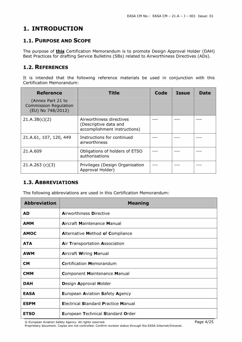
1.2. REFERENCES
It is intended that the following reference materials be used in conjunction with this
Certification Memorandum:
Reference
(Annex Part 21 to
Commission Regulation
(EU) No 748/2012)
Title Code Issue Date
21.A.3B(c)(2)
Airworthiness directives
(Descriptive data and
accomplishment instructions)
--- --- ---
21.A.61, 107, 120, 449
Instructions for continued
airworthiness
--- --- ---
21.A.609
Obligations of holders of ETSO
authorisations
--- --- ---
21.A.263 (c)(3) Privileges (Design Organisation
Approval Holder)
--- --- ---
1.3. ABBREVIATIONS
The following abbreviations are used in this Certification Memorandum:
Abbreviation Meaning
AD Airworthiness Directive
AMM Aircraft Maintenance Manual
AMOC Alternative Method of Compliance
ATA Air Transportation Association
AWM Aircraft Wiring Manual
CM Certification Memorandum
CMM Component Maintenance Manual
DAH Design Approval Holder
EASA European Aviation Safety Agency
ESPM Electrical Standard Practice Manual
ETSO European Technical Standard Order
EASA CM No.: EASA CM – 21.A – J – 001 Issue: 01
© European Aviation Safety Agency. All rights reserved. Page 5/25 Proprietary document. Copies are not controlled. Confirm revision status through the EASA-Internet/Intranet.
Abbreviation Meaning
FAA Federal Aviation Administration
FIM Fault Isolation Manual
ICA Instructions for Continued Airworthiness
MRBR Maintenance Review Board Report
NDT Non-Destructive Test
OHM Overhaul Manual
SB Service Bulletin
SOPM Standard Overhaul Practices Manual
SRM Structural Repair Manual
STC Supplemental Type Certificate
SWPM Standard Wiring Practices Manual
TSM Trouble Shooting Manual
WDM Wiring Diagram Manual
1.4. DEFINITIONS
The following definitions are used in this Certification Memorandum:
Definition Meaning
--- ---
EASA CM No.: EASA CM – 21.A – J – 001 Issue: 01
© European Aviation Safety Agency. All rights reserved. Page 6/25 Proprietary document. Copies are not controlled. Confirm revision status through the EASA-Internet/Intranet.
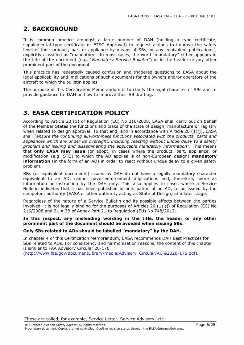
2. BACKGROUND
It is common practice amongst a large number of DAH (holding a type certificate,
supplemental type certificate or ETSO Approval) to request actions to improve the safety
level of their product, part or appliance by means of SBs, or any equivalent publications1,
explicitly classified as “mandatory”. In most cases, the word “mandatory” either appears in
the title of the document (e.g. “Mandatory Service Bulletin”) or in the header or any other
prominent part of the document.
This practice has repeatedly caused confusion and triggered questions to EASA about the
legal applicability and implications of such documents for the owners and/or operators of the
aircraft to which the bulletin applies.
The purpose of this Certification Memorandum is to clarify the legal character of SBs and to
provide guidance to DAH on how to improve their SB drafting.
3. EASA CERTIFICATION POLICY
According to Article 20 (1) of Regulation (EC) No 216/2008, EASA shall carry out on behalf
of the Member States the functions and tasks of the state of design, manufacture or registry
when related to design approval. To that end, and in accordance with Article 20 (1)(j), EASA
shall “ensure the continuing airworthiness functions associated with the products, parts and
appliances which are under its oversight, including reacting without undue delay to a safety
problem and issuing and disseminating the applicable mandatory information”. This means
that only EASA may issue (or adopt, in cases where the product, part, appliance, or
modification (e.g. STC) to which the AD applies is of non-European design) mandatory
information (in the form of an AD) in order to react without undue delay to a given safety
problem.
SBs (or equivalent documents) issued by DAH do not have a legally mandatory character
equivalent to an AD, cannot have enforcement implications and, therefore, serve as
information or instruction by the DAH only. This also applies to cases where a Service
Bulletin indicates that it has been published in anticipation of an AD, to be issued by the
competent authority (EASA or other authority acting as State of Design) at a later stage.
Regardless of the nature of a Service Bulletin and its possible effects between the parties
involved, it is not legally binding for the purposes of Articles 20 (1) (j) of Regulation (EC) No
216/2008 and 21.A.3B of Annex Part 21 to Regulation (EU) No 748/2012.
In this respect, any misleading wording in the title, the header or any other
prominent part of the document should be avoided when issuing SBs.
Only SBs related to ADs should be labelled “mandatory” by the DAH.
In chapter 4 of this Certification Memorandum, EASA recommends DAH Best Practices for
SBs related to ADs. For consistency and harmonisation reasons, the content of this chapter
is similar to FAA Advisory Circular 20-176
(http://www.faa.gov/documentLibrary/media/Advisory_Circular/AC%2020-176.pdf).
1These are called, for example, Service Letter, Service Advisory, etc.
EASA CM No.: EASA CM – 21.A – J – 001 Issue: 01
© European Aviation Safety Agency. All rights reserved. Page 7/25 Proprietary document. Copies are not controlled. Confirm revision status through the EASA-Internet/Intranet.
4. EASA-RECOMMENDED DESIGN APPROVAL HOLDER BEST PRACTICES FOR SERVICE BULLETINS RELATED TO
AIRWORTHINESS DIRECTIVES
4.1. USER-FRIENDLY SERVICE BULLETINS
4.1.1. General
This chapter provides best practices and recommendations on how DAHs can improve the
quality and usability of SBs associated with an AD action. It also provides guidance for
streamlining the SB development and revision processes for such SBs.
4.1.2. SB Improvements
a. A SB referenced in an AD as a source of information about the unsafe condition, should be
written so that owners/operators and maintenance organisations can understand and follow
the accomplishment instructions. The following SB improvements will be discussed further in
this chapter:
(1) Providing a standardised format and structure so the reader can easily locate
important information on effectivity, compliance times, and accomplishment instructions.
See paragraph 4.1.3. of this CM.
(2) Including a clear and concise description of the safety intent of the SB as well as a
precise description of the new configuration that removes the unsafe condition. See
paragraph 4.1.4. of this CM.
(3) Writing clear, concise, and unambiguous technical instructions that minimize the
possibility of omission, error, or extensive judgment. See paragraphs 4.1.5. and 4.1.6. of
this CM.
(4) Giving clear, detailed illustrations appropriate to the task, and that help the user
understand how to sequence and accomplish the tasks and/or steps. See paragraphs
4.1.7. and 4.1.8. of this CM.
(5) Allowing use of industry standards or operator practices acceptable to EASA. See
paragraph 4.1.9. of this CM.
(6) Streamlining the SB development and revision processes. See paragraph 4.1.10. of
this CM.
b. The concepts presented in this CM apply to development of new or revised SBs and are
not intended to be applied retroactively, except when deemed necessary by the DAH and
EASA.
4.1.3. Standardised Format and Content
a. The format and content of a SB should follow industry specifications for technical
documents. Refer to the following documents:
(1) Air Transportation Association (ATA) Spec 2200, Information Standards for Aviation
Maintenance.
EASA CM No.: EASA CM – 21.A – J – 001 Issue: 01
© European Aviation Safety Agency. All rights reserved. Page 8/25 Proprietary document. Copies are not controlled. Confirm revision status through the EASA-Internet/Intranet.
(2) S1000D, International Specification for Technical Publications.
b. The accomplishment instructions in a SB should address resolving the unsafe condition
identified in the SB and in the AD. Sometimes, however, procedures are already published in
other DAH documents which accomplish this goal. As such, the following guidelines at point
(1) are provided to help determine what procedures should preferably be included in a SB,
while at point (2) to help determine what procedures should not preferably be included in a
SB:
(1) When appropriate, include the following types of procedures in the SB:
(a) Inspection or test procedures that do not exist in a published DAH document
available to other parties.
(b) Critical requirements are requirements which are required for the compliance
with the AD, such as torque values, gap measurements, electrical bonding, etc.) in
procedures that exist in manuals . List in the SB the critical requirements that must
be met to comply with a planned AD and refer to the procedure in the manual as an
accepted procedure to achieve those requirements (see paragraph 4.1.9 of this CM).
(c) Revised procedures when the original procedure(s) are in error.
(2) Do not duplicate (e.g., copy) the following types of procedures in a SB. Instead of
repeating the procedure, refer to the other document(s) for that task. Be careful,
however, because any change to the procedures referenced in the other document(s) in a
SB that will be required for compliance with an AD might require an AMOC approval.
(a) Procedures that exist in other documents accessible by other parties (e.g., DAH
SBs/manuals, component SBs, and supplier SBs).
(b) Common industry practices such as, but not limited to, the Standard Overhaul
Practices Manual (SOPM) and Electrical Standard Practice Manual (ESPM)/Standard
Wiring Practices Manual (SWPM).
(c) Tests for all components or systems that may be disturbed during incorporation
of a SB. A SB should specify only the testing necessary to ensure the new or
modified system operates as intended after the modification is complete (i.e.,
unsafe condition is resolved). Any additional functional tests that may be necessary
due to an interruption to other aircraft systems should be listed by reference to
existing documents or addressed in a general note in the SB (see Annex I,
paragraph 5).
c. If a SB references other documents that will be required for compliance with an AD
(reference paragraphs 4.1.9 and 4.1.10 of this CM), include the revision level and date of
the other document(s). If applicable, the acceptability of later versions of documents may be
mentioned in the SB. Use the following guidelines when referring to other documents in a
SB:
(1) Specify the specific section(s) of the document that are applicable. Do not provide a
blanket reference to the other document if only portions of the other document are
applicable.
(2) Do not refer to documents that simply refer to other documents. Instead refer to the
end document that provides the actual instruction.
(3) Do not refer to documents that do not provide sufficient information to perform the
task (e.g., “Cad plate per SOPM AA-XX-YY” if document SOPM AA-XX-YY does not specify
the type of cad plating for the specific part).
EASA CM No.: EASA CM – 21.A – J – 001 Issue: 01
© European Aviation Safety Agency. All rights reserved. Page 9/25 Proprietary document. Copies are not controlled. Confirm revision status through the EASA-Internet/Intranet.
4.1.4. Safety Intent and Configuration Description
a. When drafting a SB that might be made mandatory by an AD, the SB should contain
paragraphs (or sub-paragraphs) entitled “Safety Intent”, or similar, and for ADs that will
change the configuration of a part, “Configuration Description.” Place the paragraphs next to
one another upfront in the SB, for example after the “Reason” paragraph. These paragraphs
are intended to enhance and focus awareness of the safety issue during the development
and approval of the SB by the DAH as well as during implementation and subsequent
maintenance. If deemed necessary, the “Safety Intent” may be part of the “Reason”
paragraph, provided that the conditions explained here below apply.
(1) The “Safety Intent” paragraph (or sub-paragraph) should explain what
accomplishment of the SB is intended to do (i.e., prevent, resolve, or otherwise remove
the unsafe condition). The description should be a succinct and clear statement of the
specific technical objective of the instructions. For example, “The safety intent of this SB
is to prevent electrical arcing between a wire bundle and control cables in the main wheel
well, which, if not corrected, could cause a hydraulic or electrical fire.” The goal is to
explain in technical terms what is the affected part and failure mode or malfunction, and
how it will be prevented, resolved, or otherwise removed by accomplishing the SB. This
differs from the “Reason” paragraph in most SBs which typically provide the history and
reason for taking the SB action.
(2) If accomplishing the SB will change configuration, a “Configuration Description”
paragraph should be included to provide a succinct, high-level description of the design
change that will result from accomplishing the instructions. For example, “Incorporating
this SB results in installing a new wire bundle (P/N 123456) between the J135 and J234
connectors, and installing several standoffs of increased length to hold the wire bundle
clear of contact.” The “Configuration Description” should:
(a) Be limited to the features that will prevent development or recurrence of the
unsafe condition, once the configuration has been implemented. The paragraph can
provide the greatest value in SBs that specify ‘high risk’ modifications (e.g.,
instructions that are complex, workmanship intensive, or susceptible to reversal in
operations, i.e. unintended de-modifications).
(b) Assist in understanding the post-installation mandated configuration. The
“Configuration Description” may guide, but cannot be used as the final determinant of
compliance with an AD.
(c) For an AD that will require installation of a different part, the part number of the
new part should differ from that of the original. If changing the part number (i.e.,
“rolling” the part number) is impractical, identify the “modification level” of the part.
The configuration description for this case should control the part by the “modification
level” in addition to the part number identification.
(d) Identify a specific part, sub-assembly, or assembly of a component affected by
the safety intent. An affected component “part number” may contain, both defective
and non-defective parts, sub-assemblies, or assemblies. But because the part number
of the component might not have been changed or “rolled” to differentiate the
configurations, identification using the component part number alone is inadequate.
Therefore, the configuration description for such a case should control the specific
parts, sub-assemblies, or assemblies in addition to the part number identification of
the affected component.
b. For SBs originally written for reliability or economic enhancements that subsequently are
found to provide correction of a safety issue, those SB should be revised to include the
“Safety Intent” and “Configuration Description” paragraphs per the guidance in this CM.
EASA CM No.: EASA CM – 21.A – J – 001 Issue: 01
© European Aviation Safety Agency. All rights reserved. Page 10/25 Proprietary document. Copies are not controlled. Confirm revision status through the EASA-Internet/Intranet.
4.1.5. Unambiguous Language
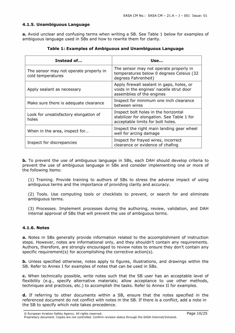
a. Avoid unclear and confusing terms when writing a SB. See Table 1 below for examples of
ambiguous language used in SBs and how to rewrite them for clarity.
Table 1: Examples of Ambiguous and Unambiguous Language
Instead of… Use…
The sensor may not operate properly in
cold temperatures
The sensor may not operate properly in
temperatures below 0 degrees Celsius (32
degrees Fahrenheit)
Apply sealant as necessary
Apply firewall sealant in gaps, holes, or
voids in the engines’ nacelle strut door
assemblies of the engines
Make sure there is adequate clearance Inspect for minimum one inch clearance
between wires
Look for unsatisfactory elongation of
holes
Inspect bolt holes in the horizontal
stabilizer for elongation. See Table 1 for
acceptable limits for bolt holes.
When in the area, inspect for… Inspect the right main landing gear wheel
well for arcing damage
Inspect for discrepancies Inspect for frayed wires, incorrect
clearance or evidence of chafing
b. To prevent the use of ambiguous language in SBs, each DAH should develop criteria to
prevent the use of ambiguous language in SBs and consider implementing one or more of
the following items:
(1) Training. Provide training to authors of SBs to stress the adverse impact of using
ambiguous terms and the importance of providing clarity and accuracy.
(2) Tools. Use computing tools or checklists to prevent, or search for and eliminate
ambiguous terms.
(3) Processes. Implement processes during the authoring, review, validation, and DAH
internal approval of SBs that will prevent the use of ambiguous terms.
4.1.6. Notes
a. Notes in SBs generally provide information related to the accomplishment of instruction
steps. However, notes are informational only, and they shouldn’t contain any requirements.
Authors, therefore, are strongly encouraged to review notes to ensure they don’t contain any
specific requirement(s) for accomplishing the corrective action(s).
b. Unless specified otherwise, notes apply to figures, illustrations, and drawings within the
SB. Refer to Annex I for examples of notes that can be used in SBs.
c. When technically possible, write notes such that the SB user has an acceptable level of
flexibility (e.g., specify alternative materials; allow acceptance to use other methods,
techniques and practices, etc.) to accomplish the tasks. Refer to Annex II for examples.
d. If referring to other documents within a SB, ensure that the notes specified in the
referenced document do not conflict with notes in the SB. If there is a conflict, add a note in
the SB to specify which note takes precedence.
EASA CM No.: EASA CM – 21.A – J – 001 Issue: 01
© European Aviation Safety Agency. All rights reserved. Page 11/25 Proprietary document. Copies are not controlled. Confirm revision status through the EASA-Internet/Intranet.
e. Notes should be preferably placed at the beginning of the accomplishment instructions or
alternatively after the text they relate to, and may include items such as:
(1) Referring to a list or document of acceptable alternative parts, materials, and
processes,
(2) Specifying or referring to other documents for standard tolerances and dimensions,
(3) Specifying standard practices that apply to the entire set of accomplishment
instructions,
(4) Providing definitions for inspections specified in the service information, and
(5) Referring to DAH maintenance documentation.
In addition, warnings and cautions applying to the entire set of accomplishment
instructions should be preferably placed at the beginning of the accomplishment
instructions.
4.1.7. Figures, Illustrations, and Drawings
a. To avoid subjective misinterpretation, the text in the accomplishment instructions should
be the authoritative information. Use figures, illustrations, and drawings to supplement the
accomplishment instructions. If a discrepancy between the accomplishment instructions and
a figure, illustration, or drawing exists, the discrepancy should be evaluated and corrected.
b. Dimensions should be added to clearly define locations, e.g., installation of parts.
c. Tolerances should be included for measured values (e.g., dimensions, torque values,
temperature). This can be done in the figure, illustration, or drawing itself, or in general
notes in the service bulletin (e.g. “All dimensions given have a tolerance of +/- 5mm unless
otherwise stated.”)
d. Phantom lines, shading/cross hatching, and enlarged views should be used to assist in
distinguishing important information from “reference only” information. Refer to Annex III
for examples.
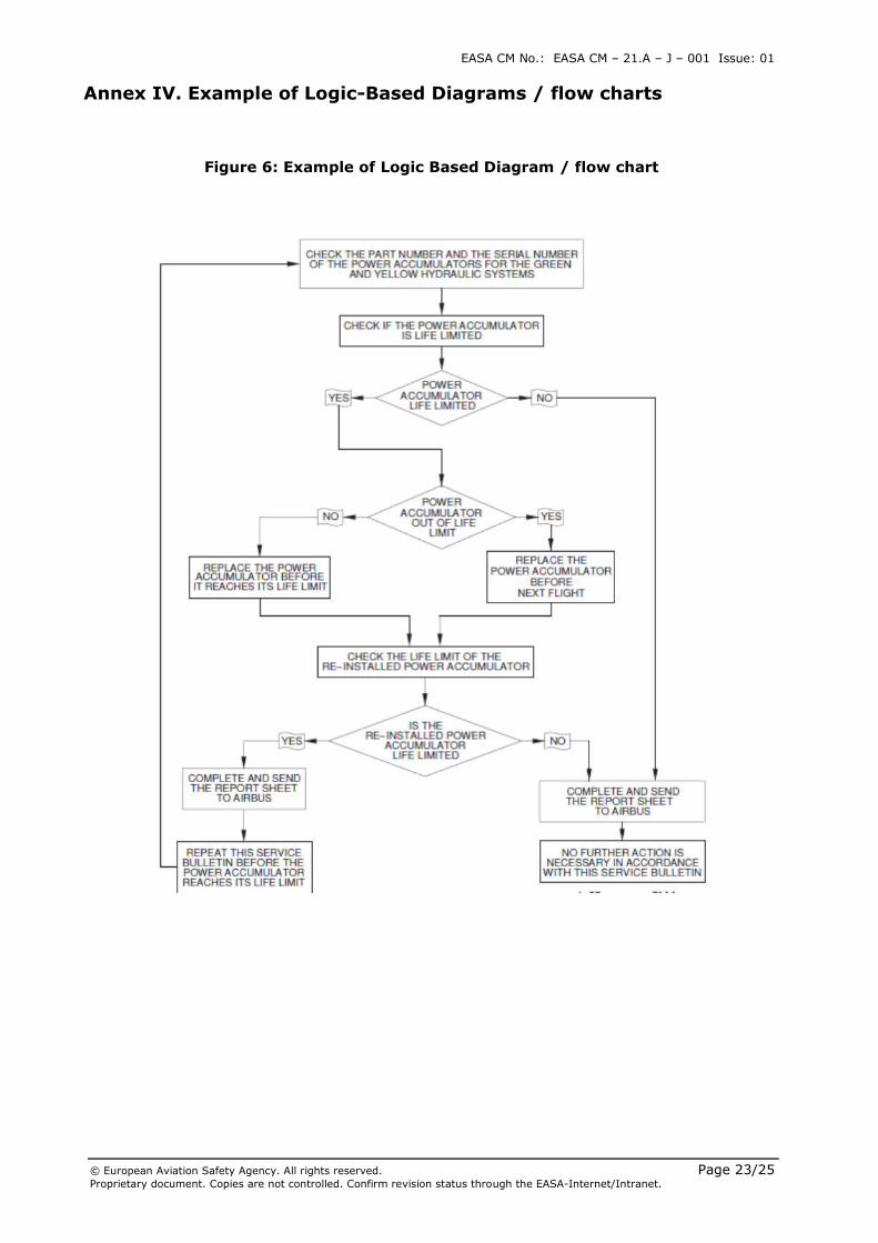
4.1.8. Logic-based Diagrams / flow chart
A SB specifying numerous compliance times, configurations, conditions, and alternative
corrective actions can be difficult to follow. For such cases, a logic-based diagram / flowchart
is a useful tool to assist owners/operators in identifying the intended corrective path.
a. It is the responsibility of the DAH to determine if logic-based diagrams/flow charts
would help simplify a complex SB. Consideration should be given to any request from
operators or EASA as to whether a logic-based diagram/flow chart would be helpful.
b. A logic-based diagram/flow chart cannot be the primary source for tasks or compliance
times in the SB. If used, logic-based diagrams/flow charts should:
(1) Use descriptive, concise, and consistent terminology, and
(2) Contain a note in both the logic-based diagram/flow chart and the
accomplishment instructions paragraph of the SB to be clear that the logic-based
diagram/flow chart only supplements the information in the accomplishment
instructions.
EASA CM No.: EASA CM – 21.A – J – 001 Issue: 01
© European Aviation Safety Agency. All rights reserved. Page 12/25 Proprietary document. Copies are not controlled. Confirm revision status through the EASA-Internet/Intranet.
4.1.9. Mandatory versus Flexible Language
The use of mandatory language in the accomplishment instructions of a SB depends on
whether other procedures are adequate to address the unsafe condition in an AD. If other
procedures are acceptable, non-mandatory language should be used in the SB.
a. When a procedure or document MUST be followed to accomplish a task in a SB, the
appropriate terminology to use to cite the procedure/document is “in accordance with.”
Use “in accordance with” for:
(1) A process or procedure that must be followed exactly to resolve the unsafe
condition and comply with the AD. Also consider including the steps of the process or
procedure in the SB and a note not to change the process or procedure without full
consideration of the consequences.
(2) Documents that an organisation must use to ensure the part is installed, changed,
or tested per the specific instruction.
b. When a procedure or document MAY be followed to accomplish an action (e.g., the
DAH’s procedure or document may be used, but an organisation’s procedure could also be
used), the appropriate terminology to use to cite the procedure or document is “refer to
... as an accepted procedure.” Use this flexible language when referring to procedures
when an organisation may use the document or their own procedure.
c. When using “in accordance with” or “refer to” language in a SB, the DAH should include
a note explaining the meaning of that language. For example:
“Note: These work instructions refer to methods, techniques, and practices described
in other {specify DAH name} documents. When the words "refer to" are used and the
organisation has other acceptable methods, techniques, and practices (including
tools, equipment, and test equipment), those acceptable methods, techniques,
practices (including tools, equipment, and test equipment) may be used to complete
the work. When the words "in accordance with" are included in the instruction, the
methods, techniques, and practices specified (including tools, equipment, and test
equipment) in the {specify DAH name} document must be used.”
4.1.10. Streamlining Development and Revision of SBs
a. Each DAH should have systems in place to continuously monitor and implement process
improvements in both the development and revision of SBs. The system should help improve
processes involving the quality of SBs as well as reducing flow time to produce those SBs.
b. It is important to remember that for any change to an SB, such as a partial or temporary
revision, after the SB is referenced in an AD, EASA has to be informed, to identify whether
the SB change is non-substantial (e.g. typos correction) or might affect the requirements of
the corresponding AD. In the latter case, a change approval process must be sought.
c. Below are examples of process improvements implemented by various DAH(s) to reduce
flow time and improve the quality of SBs. Each DAH should review the list of items and
evaluate the feasibility of implementing items from the list, or identify alternatives or
equivalents that would improve SB processes.
(1) Use of Checklists and Guidance Material – Implemented to assist authors in making
sure requirements are met before documents are sent for approval.
EASA CM No.: EASA CM – 21.A – J – 001 Issue: 01
© European Aviation Safety Agency. All rights reserved. Page 13/25 Proprietary document. Copies are not controlled. Confirm revision status through the EASA-Internet/Intranet.
(2) Use of Templates – Implemented to standardise the location and content of text in
SBs, which reduces variation.
(3) Dispute Resolution Process – An informal process where a DAH communicates early
and often in the SB process with the Agency for early resolution of issues.
(4) Validation Process – A formal process used to validate that the procedures in SBs are
accurate, and that hardware kits/parts are complete and can be accomplished per the
accomplishment instructions.
(5) Partial Revision Process – A process in which only changed information in a SB is sent
to affected customers.
(6) Temporary Revision Process – A process in which only changed information in a
document is sent to affected customers. The information is later included in the next
scheduled revision cycle for the document.
(7) Information Exchange Process – A process in which a DAH shares information used to
develop service information. For example, posting the proposed solutions, proposed
compliance times, estimated parts availability dates, and other information regarding
plans for resolving an unsafe condition on the DAH website. Designated parties can then
view the information and provide feedback back to the DAH.
(8) Airworthiness Concern Coordination Process – A process in which a DAH, operators,
and a regulatory agency work together to develop actions and accomplishment
instructions necessary to resolve an unsafe condition.
4.2. AVOIDING OVERLAPPING AND CONFLICTING ACTIONS IN SBS
4.2.1. General
This chapter provides a recommended process for DAHs to track AD-related SBs to ensure
that they do not contain overlapping or conflicting actions that could lead to a non-
compliance with an AD.
4.2.2. Tracking and Management Process
A DAH should develop a robust SB/AD tracking and management system using the following
process to ensure overlaps and conflicts between new and existing SB actions are identified
and addressed.
a. Search capabilities should include the following primary areas:
(1) Type/model or part number of affected component(s),
(2) Major aircraft elements (e.g., engine, strut, wing, etc.),
(3) ATA code,
(4) Maintenance zones,
(5) Service information (e.g., service bulletin number),
(6) Airworthiness limitation sections,
EASA CM No.: EASA CM – 21.A – J – 001 Issue: 01
© European Aviation Safety Agency. All rights reserved. Page 14/25 Proprietary document. Copies are not controlled. Confirm revision status through the EASA-Internet/Intranet.
(7) Previously issued ADs, and
(8) Planned ADs (i.e., action(s) that EASA intends to mandate in an AD).
b. When developing a new SB that will be associated with an AD, the DAH should search for
any existing or planned ADs in, or affecting, the area of the new AD action and determine
whether there are potential overlapping and/or conflicting requirements that could lead to
non-compliance with any existing AD(s).
c. The DAH should document and maintain a record of its findings.
d. Upon review of the findings, the DAH should resolve any conflicting actions, e.g., the DAH
might develop a new design and/or inspection.
e. Finally, the DAH should notify EASA of the results of its review and resolution of any
conflicting issues prior to approval of the new design change or issuance of the SB.
4.3. MAINTAINING AIRWORTHINESS OR AD-MANDATED DESIGN
CHANGES
4.3.1. General
This chapter provides guidance to DAHs for helping owners/operators and maintenance
organisations avoid inadvertently undoing or modifying AD-mandated type designs through
routine maintenance practices.
4.3.2. Maintenance of an AD-Mandated Design Change.
Once a product’s approved design is changed by an AD, owners/operators may perform
routine maintenance if that maintenance does not result in changing the AD-mandated
configuration.
a. The potential for undoing an AD-mandated configuration should be evaluated during all
stages of design and development of SBs, or other maintenance documents (e.g., during the
review of the SB or maintenance document; SB prototyping/validation; and PAD
consultation period).
b. To decrease the chances that maintenance will inadvertently undo or modify an AD-
mandated type design, the following actions should be performed by DAHs:
(1) During the design change and SB development stages, evaluate the need for changes
to maintenance documents to eliminate the potential for undoing an AD-mandated
condition or configuration. Update any maintenance document to support the AD-
mandated type design changes.
(2) Provide awareness to owners/operators regarding availability of updated maintenance
documents.
(3) When drafting SBs, use notes for flexibility and refer to standard practices as much as
possible (see paragraph 4.1.6.e (4) of this CM).
(4) When drafting SBs, avoid duplicating entire procedures/instructions that reside in
other maintenance documents. The SB should only list the specific requirement which
must be met, not the entire procedure (see paragraph 4.1.3.b of this CM). Internal flags
should then be placed in the associated maintenance document where the requirement is
EASA CM No.: EASA CM – 21.A – J – 001 Issue: 01
© European Aviation Safety Agency. All rights reserved. Page 15/25 Proprietary document. Copies are not controlled. Confirm revision status through the EASA-Internet/Intranet.
located to indicate that it addresses an AD compliance requirement (see paragraph 4.3.5
of this CM).
(5) Create a SB-to-AD cross-reference listing upon release of the AD (see paragraph 4.3.6
of this CM).
4.3.3. Availability of Maintenance Documents
A DAH should make new maintenance documents or changes to them available as early as
possible to owners/operators when an AD-related SB is issued (e.g., prior to the effective
date of the AD).
Doing so helps ensure that owners/operators have the appropriate maintenance documents
necessary to maintain the product upon accomplishing or complying with the AD.
4.3.4. Flagging Procedures
When a SB specifies requirements that exist in another maintenance document (e.g., an
AMM), or when the SB instruction includes language to accomplish a procedure “in
accordance with” a manual (see paragraph 4.1.9 of this CM) (e.g., the SRM), the
requirement/procedure in the document from which the requirement were duplicated, or the
referenced document, should be flagged by the DAH. The procedure should be flagged in a
manner that identifies that the procedure/requirement in the document held by the DAH is
mandated by an AD. The flagged language should:
a. Be visible to the maintenance documentation authors for their use (i.e., not on the
maintenance documents provided to the operators).
b. Contain a note similar to the following or list the SB and AD number once it becomes
available:
Note: This procedure is used for maintaining compliance with SB XYZ, which is subject
to or mandated by an AD.
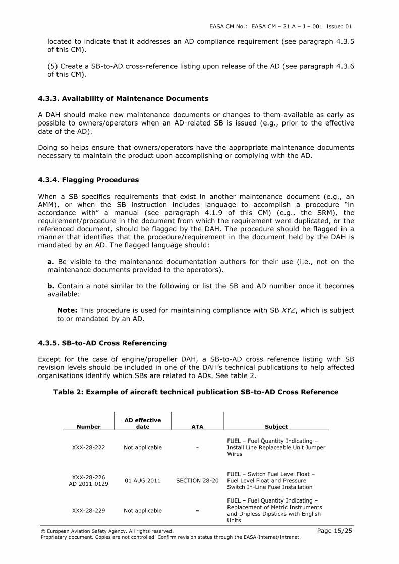
4.3.5. SB-to-AD Cross Referencing
Except for the case of engine/propeller DAH, a SB-to-AD cross reference listing with SB
revision levels should be included in one of the DAH’s technical publications to help affected
organisations identify which SBs are related to ADs. See table 2.
Table 2: Example of aircraft technical publication SB-to-AD Cross Reference
Number AD effective
date ATA Subject
XXX-28-222 Not applicable - FUEL – Fuel Quantity Indicating – Install Line Replaceable Unit Jumper Wires
XXX-28-226 AD 2011-0129
01 AUG 2011 SECTION 28-20 FUEL – Switch Fuel Level Float – Fuel Level Float and Pressure Switch In-Line Fuse Installation
XXX-28-229 Not applicable -
FUEL – Fuel Quantity Indicating – Replacement of Metric Instruments and Dripless Dipsticks with English Units
EASA CM No.: EASA CM – 21.A – J – 001 Issue: 01
© European Aviation Safety Agency. All rights reserved. Page 16/25 Proprietary document. Copies are not controlled. Confirm revision status through the EASA-Internet/Intranet.
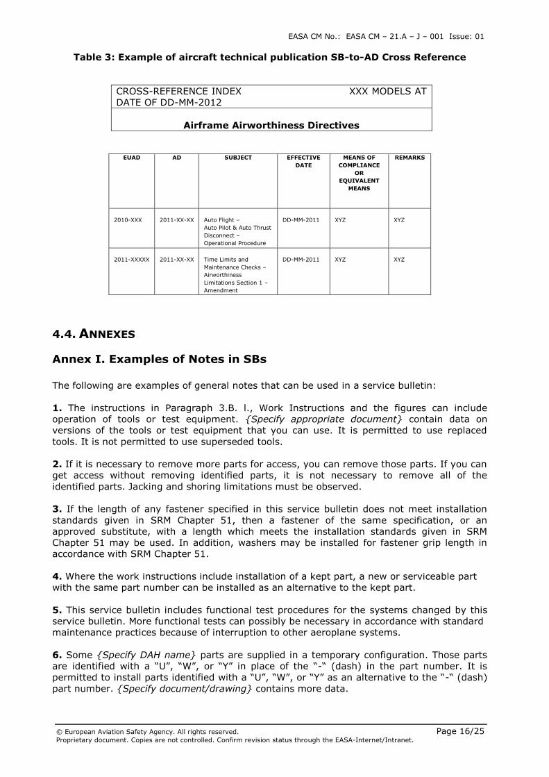
Table 3: Example of aircraft technical publication SB-to-AD Cross Reference
CROSS-REFERENCE INDEX XXX MODELS AT
DATE OF DD-MM-2012
Airframe Airworthiness Directives
4.4. ANNEXES
Annex I. Examples of Notes in SBs
The following are examples of general notes that can be used in a service bulletin:
1. The instructions in Paragraph 3.B. l., Work Instructions and the figures can include
operation of tools or test equipment. {Specify appropriate document} contain data on
versions of the tools or test equipment that you can use. It is permitted to use replaced
tools. It is not permitted to use superseded tools.
2. If it is necessary to remove more parts for access, you can remove those parts. If you can
get access without removing identified parts, it is not necessary to remove all of the
identified parts. Jacking and shoring limitations must be observed.
3. If the length of any fastener specified in this service bulletin does not meet installation
standards given in SRM Chapter 51, then a fastener of the same specification, or an
approved substitute, with a length which meets the installation standards given in SRM
Chapter 51 may be used. In addition, washers may be installed for fastener grip length in
accordance with SRM Chapter 51.
4. Where the work instructions include installation of a kept part, a new or serviceable part
with the same part number can be installed as an alternative to the kept part.
5. This service bulletin includes functional test procedures for the systems changed by this
service bulletin. More functional tests can possibly be necessary in accordance with standard
maintenance practices because of interruption to other aeroplane systems.
6. Some {Specify DAH name} parts are supplied in a temporary configuration. Those parts
are identified with a “U”, “W”, or “Y” in place of the “-“ (dash) in the part number. It is
permitted to install parts identified with a “U”, “W”, or “Y” as an alternative to the “-“ (dash)
part number. {Specify document/drawing} contains more data.
EUAD AD SUBJECT EFFECTIVE
DATE
MEANS OF
COMPLIANCE
OR
EQUIVALENT
MEANS
REMARKS
2010-XXX
2011-XX-XX
Auto Flight –
Auto Pilot & Auto Thrust
Disconnect –
Operational Procedure
DD-MM-2011
XYZ
XYZ
2011-XXXXX
2011-XX-XX
Time Limits and
Maintenance Checks –
Airworthiness
Limitations Section 1 –
Amendment
DD-MM-2011
XYZ
XYZ
EASA CM No.: EASA CM – 21.A – J – 001 Issue: 01
© European Aviation Safety Agency. All rights reserved. Page 17/25 Proprietary document. Copies are not controlled. Confirm revision status through the EASA-Internet/Intranet.
Annex II. Examples of Notes that Provide Flexibility in SBs
The following are examples of notes that can be used in a SB to allow flexibility:
1. The instructions identified in Paragraph 3.B., Work Instructions and the Figure(s) give the
recommended sequence of steps. The sequence of steps may be completed first on either
the right side or left side of the aircraft .
2. Equivalent parts are listed in drawing {drawing number}.
3. Refer to SRM Chapter 51 for approved fasteners and process material substitutions.
4. If the length of any fastener specified in this service bulletin does not meet the installation
standards in SRM Chapter 51, then a fastener of the same specification, or an approved
substitute, with a length which meets the installation standards in Chapter 51 may be used.
5. A 1/8-inch stack of the same type washers called for in this service bulletin is the
maximum thickness which may be used under the fastener head or nut to counteract
accumulation of tolerances. EXCEPTION: When the available fastener length increments are
greater than 1/16-inch, a 3/16-inch thick stack of the same type washers may be used.
6. Unless shown differently these dimensions and tolerances are used:
a. Linear dimensions are in inches.
b. Tolerance on linear dimensions, other than rivet and bolt edge margins, is plus or
minus 0.03 inch.
c. Tolerance on rivet and bolt edge margin is plus or minus 0.05 inch.
d. Angular tolerance is plus or minus 2 degrees.
e. Hole dimensions for standard solid rivets are in {aeroplane model} SRM, Chapter 51.
f. Torque limits to tighten nuts and bolts are in {aeroplane model} SRM, Chapter 51.
7. The work instructions are divided into work packages. Task Hours and Elapsed Hours for
each package are given in Paragraph 1.G., Manpower. You can do each work package
independently.
8. Refer to the ESPM/SWPM 20-10-01 as accepted wire installation procedures.
9. Refer to these ESPM/SWPM chapters for applicable operations, as accepted procedures
{list applicable ESPM/SWPM chapters}.
10. Refer to {aeroplane model} AMM 20-15-11 for on-aeroplane software installation
maintenance practices and data transfer times as accepted procedures.
11.
Linear Tolerances Angular Tolerance
X.XX in. (X.X mm) X.X in. (X mm)
+/-0º30” +/-0.03 in. +/-0.1 in.
+/-0.8 mm +/-3 mm
NOTE: The tolerances above apply to the dimensions given in this
service bulletin except if specified differently.
12. This Service Bulletin Effectivity is divided into XX aircraft GROUPS according to the
relevant configuration and the SB itself is divided into XX PARTS. The SB PARTS are featured
to allow their independent accomplishment.
EASA CM No.: EASA CM – 21.A – J – 001 Issue: 01
© European Aviation Safety Agency. All rights reserved. Page 18/25 Proprietary document. Copies are not controlled. Confirm revision status through the EASA-Internet/Intranet.
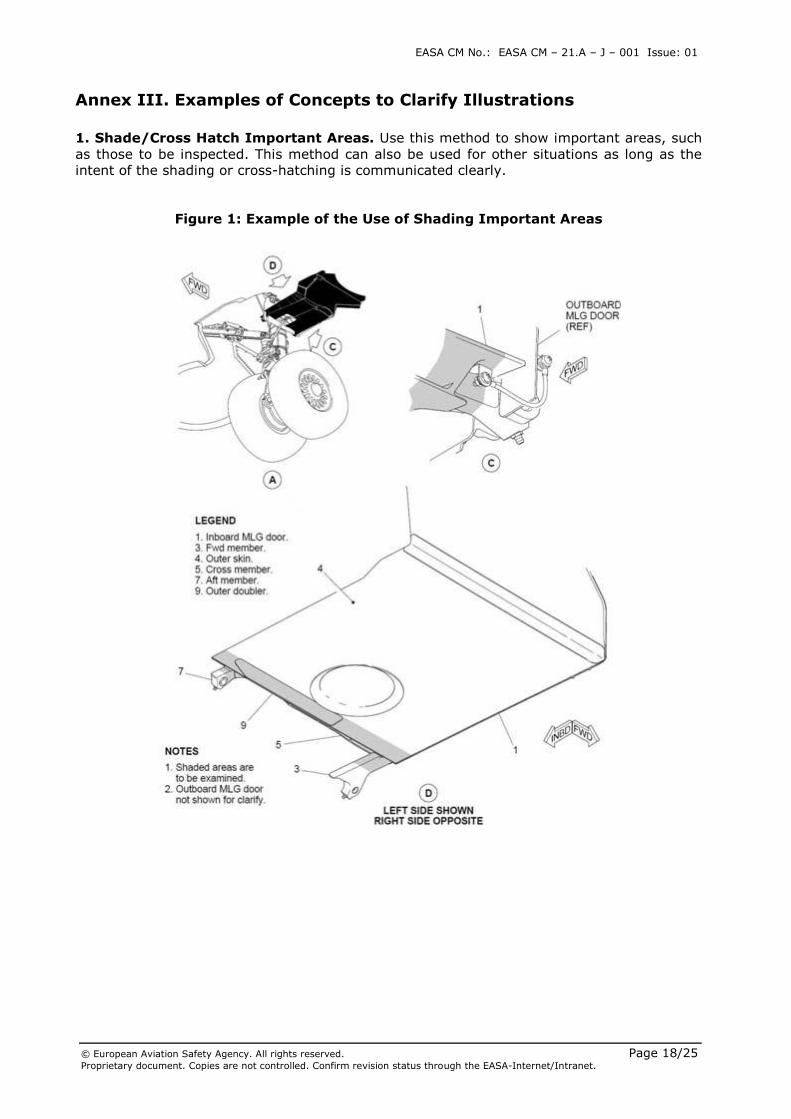
Annex III. Examples of Concepts to Clarify Illustrations
1. Shade/Cross Hatch Important Areas. Use this method to show important areas, such
as those to be inspected. This method can also be used for other situations as long as the
intent of the shading or cross-hatching is communicated clearly.
Figure 1: Example of the Use of Shading Important Areas
EASA CM No.: EASA CM – 21.A – J – 001 Issue: 01
© European Aviation Safety Agency. All rights reserved. Page 19/25 Proprietary document. Copies are not controlled. Confirm revision status through the EASA-Internet/Intranet.
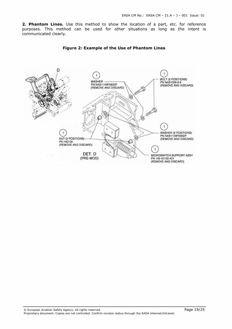
2. Phantom Lines. Use this method to show the location of a part, etc. for reference
purposes. This method can be used for other situations as long as the intent is
communicated clearly.
Figure 2: Example of the Use of Phantom Lines
EASA CM No.: EASA CM – 21.A – J – 001 Issue: 01
© European Aviation Safety Agency. All rights reserved. Page 20/25 Proprietary document. Copies are not controlled. Confirm revision status through the EASA-Internet/Intranet.
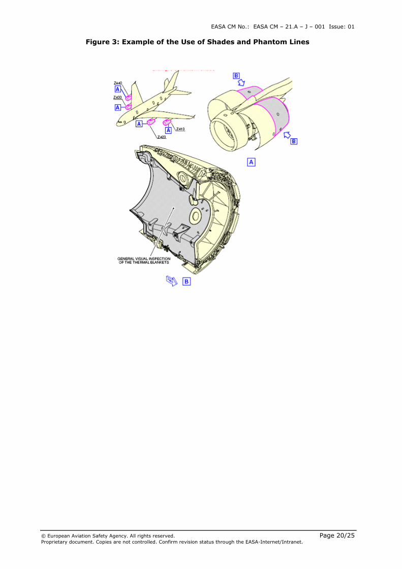
Figure 3: Example of the Use of Shades and Phantom Lines
EASA CM No.: EASA CM – 21.A – J – 001 Issue: 01
© European Aviation Safety Agency. All rights reserved. Page 21/25 Proprietary document. Copies are not controlled. Confirm revision status through the EASA-Internet/Intranet.
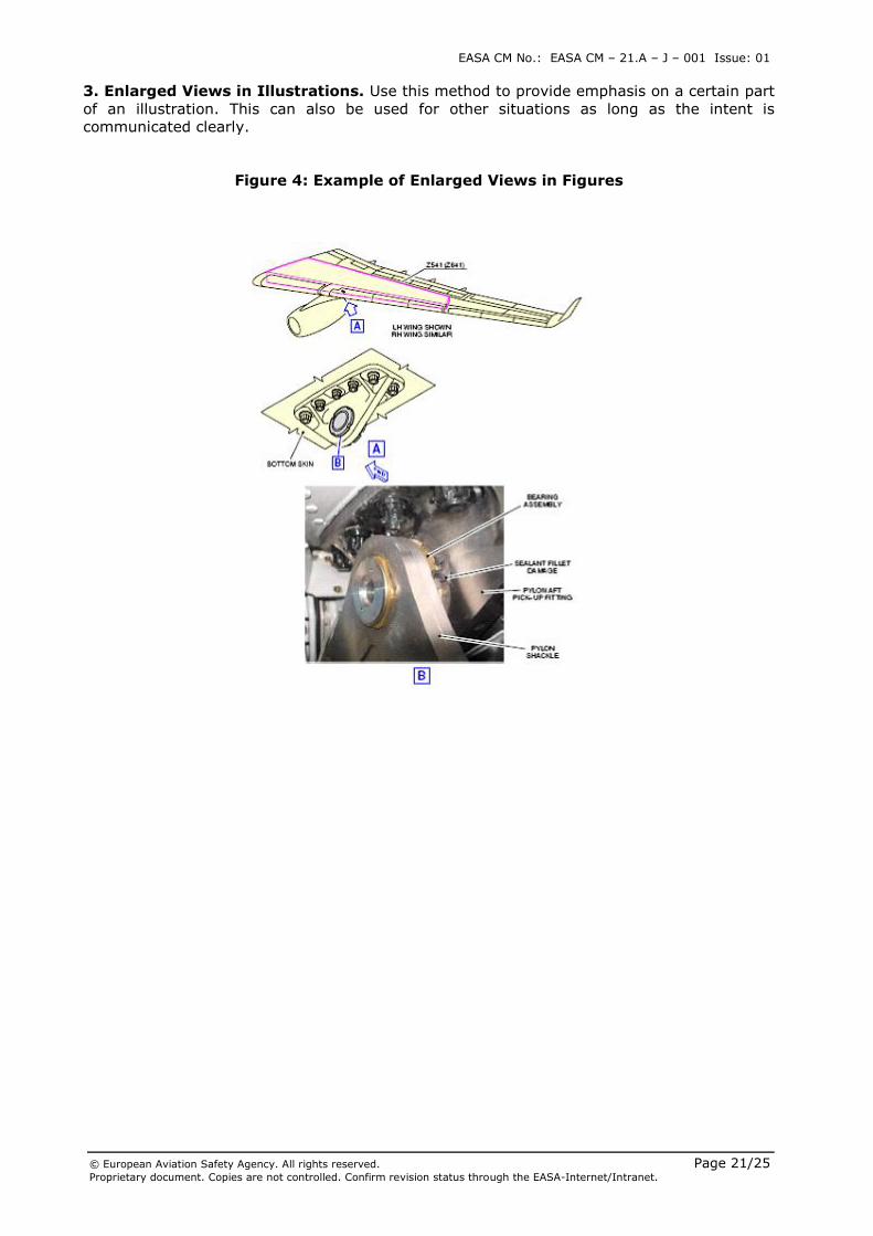
3. Enlarged Views in Illustrations. Use this method to provide emphasis on a certain part
of an illustration. This can also be used for other situations as long as the intent is
communicated clearly.
Figure 4: Example of Enlarged Views in Figures
EASA CM No.: EASA CM – 21.A – J – 001 Issue: 01
© European Aviation Safety Agency. All rights reserved. Page 22/25 Proprietary document. Copies are not controlled. Confirm revision status through the EASA-Internet/Intranet.
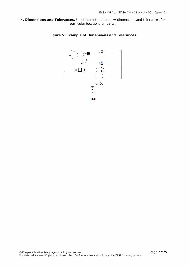
4. Dimensions and Tolerances. Use this method to show dimensions and tolerances for
particular locations on parts.
Figure 5: Example of Dimensions and Tolerances
EASA CM No.: EASA CM – 21.A – J – 001 Issue: 01
© European Aviation Safety Agency. All rights reserved. Page 23/25 Proprietary document. Copies are not controlled. Confirm revision status through the EASA-Internet/Intranet.
Annex IV. Example of Logic-Based Diagrams / flow charts
Figure 6: Example of Logic Based Diagram / flow chart
EASA CM No.: EASA CM – 21.A – J – 001 Issue: 01
© European Aviation Safety Agency. All rights reserved. Page 24/25 Proprietary document. Copies are not controlled. Confirm revision status through the EASA-Internet/Intranet.
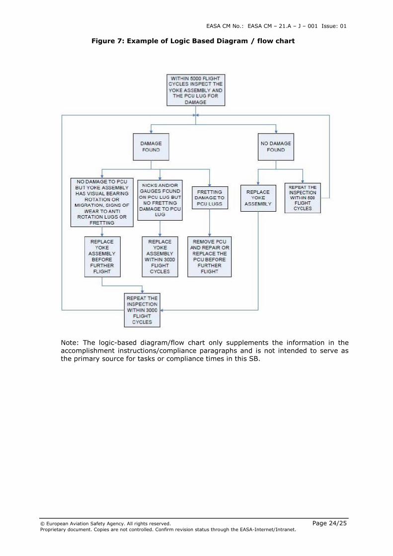
Figure 7: Example of Logic Based Diagram / flow chart
Note: The logic-based diagram/flow chart only supplements the information in the
accomplishment instructions/compliance paragraphs and is not intended to serve as
the primary source for tasks or compliance times in this SB.
EASA CM No.: EASA CM – 21.A – J – 001 Issue: 01
© European Aviation Safety Agency. All rights reserved. Page 25/25 Proprietary document. Copies are not controlled. Confirm revision status through the EASA-Internet/Intranet.
4.5. WHO THIS CERTIFICATION MEMORANDUM AFFECTS
This Certification Memorandum affects all DAH issuing SBs, either under DOA privilege as
defined in Article 21.A.263 (c)(3) of Annex Part 21 to Commission Regulation (EU) No
748/2012 or not, as well as the addressees of such Service Bulletins.
5. REMARKS
1. Suggestions for amendment(s) to this EASA Certification Memorandum should be
referred to the Certification Policy and Planning Department, Certification Directorate,
EASA. E-mail [email protected] or fax +49 (0)221 89990 4459.
2. For any question concerning the technical content of this EASA Certification
Memorandum, please contact:
Name, First Name: Wiener, Robert
Function: Occurrence Reporting Coordination Officer
Phone: +49 (0)221 89990 4192
Facsimile: +49 (0)221 89990 4692
E-mail: [email protected]