Embed Size (px)
Citation preview

www.thalesgroup.com
Early Validation of IMA
Model-Based Safety Approach for Early Validation of
integrated and modular avionics architectures
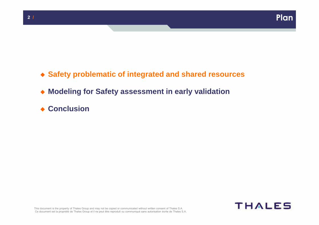
2 /2 / Plan
� Safety problematic of integrated and shared resourc es
� Modeling for Safety assessment in early validation
� Conclusion

3 /3 / Shared Resources Safety problematic
What is a shared resource system ?
� Platforms or communication network hostingseveral A/C functions
� Integrated Modular Avionics …
� Before : 1 aircraft function = 1 computer
� Now : x functions = 1 computer thanks to partitioning
� A664 network : multiplexed communication busses
� Before : ARINC 429 busses : 1 transmitter => x subscribers
� Now : 1 network : x transmitters => x subscribers
� Dedicated safety mechanisms� IMA partitioning = segregation of the avionics applications
� To allow partition faults to be contained (better robustness to faults and availability)
� To embed functions of different Development Assurance Level
� To allow systems to be developed, tested and certified separately (incremental certification)
� A664 network = deterministic routing through “Virtual Links (VL)”
� Redundancy of VL routes and Traffic Integrity (vs. corruption, babbling, etc.)
4 /4 / Shared Resources Safety problematic
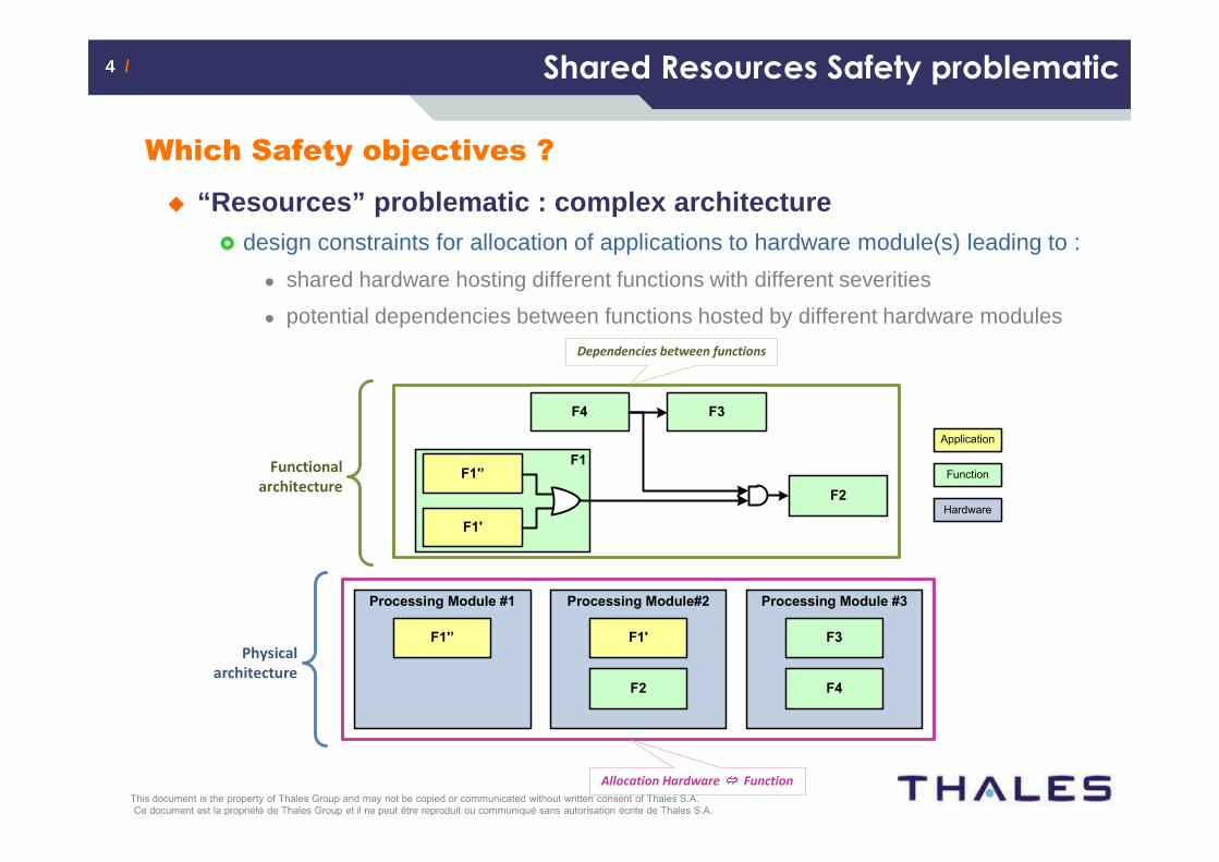
Which Safety objectives ?
� “Resources” problematic : complex architecture� design constraints for allocation of applications to hardware module(s) leading to :
� shared hardware hosting different functions with different severities
� potential dependencies between functions hosted by different hardware modules
>
F1
Processing Module #1
F1'
Hardware
Function
Application
F1'’
Processing Module#2 Processing Module #3
F1'F1'’
F2
F3
F4
F3F4
F2
Dependencies between functions
Allocation Hardware Function
Functional
architecture
Physical
architecture
5 /5 / Shared Resources Safety problematic
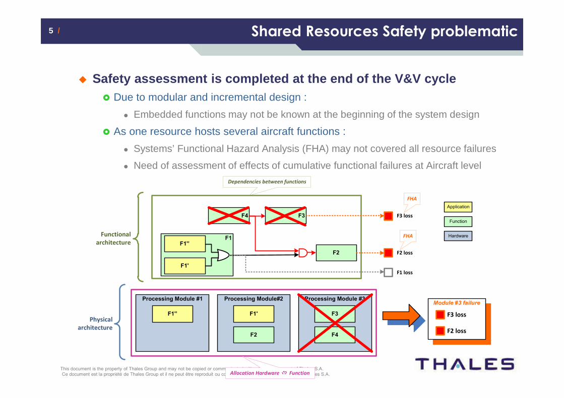
� Safety assessment is completed at the end of the V& V cycle� Due to modular and incremental design :
� Embedded functions may not be known at the beginning of the system design
� As one resource hosts several aircraft functions :
� Systems’ Functional Hazard Analysis (FHA) may not covered all resource failures
� Need of assessment of effects of cumulative functional failures at Aircraft level
>
Processing Module #1
Hardware
Function
Application
Processing Module#2 Processing Module #3
F1'F1'’
F2
F3
F4
F2 loss
F3 loss
F1 loss
Module #3 failure
F2 loss
F3 loss
FHA
FHA
Physical
architecture
Allocation Hardware Function
F1
F1'
F1'’
F3F4
F2
Dependencies between functions
Functional
architecture
6 /6 / Plan
� Safety problematic of integrated and shared resourc es
� Modeling for Safety assessment in early validation
� Conclusion

7 /7 / Towards Model-Based Safety Approach
Proven approach and tool
� Tool based on Altarica language (formalized by the La BRI)
� Altarica Dataflow variant
� Safety workbench
� Qualified and used on past civil certified programs
� Specific HMI provided by the tool
� Reusable libraries of nodes, failure rates database
� Syntax & coherence control of the code
� Interactive step-by-step simulation
8 /8 / Towards Model-Based Safety Approach
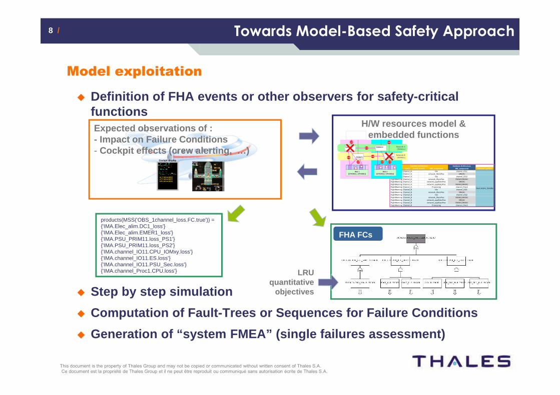
Model exploitation
� Definition of FHA events or other observers for saf ety-critical functions
� Step by step simulation
� Computation of Fault-Trees or Sequences for Failure Conditions
� Generation of “system FMEA” (single failures assessme nt)
H/W resources model & embedded functions
Expected observations of :- Impact on Failure Conditions- Cockpit effects (crew alerting, …)
Cockpit display
ALT DISAGREEATT DISAGREESPD DISAGREE
Hardware Architecture
Pattern level 1 level 2 level 3 ABS_component HW_component Function's pattern
FlightWarning Channel_A IOx channel_IO11
FlightWarning Channel_A network_IOxtoProc SWUA1
FlightWarning Channel_A IOy channel_IO12
FlightWarning Channel_A network_IOytoProc SWUA2,SWUA1
FlightWarning Channel_A network_oppIOxtoProc SWUA1
FlightWarning Channel_A network_oppIOytoProc SWUA2,SWUA1
FlightWarning Channel_A Processing channel_Proc1
FlightWarning Channel_B IOx channel_IO21
FlightWarning Channel_B network_IOxtoProc SWUA1
FlightWarning Channel_B IOy channel_IO22
FlightWarning Channel_B network_IOytoProc SWUA2,SWUA1
FlightWarning Channel_B network_oppIOxtoProc SWUA1
FlightWarning Channel_B network_oppIOytoProc SWUA2,SWUA1
FlightWarning Channel_B Processing channel_Proc3
Dual_Active_Standby
Function architecture
Network B(SWM2x)
Network A(SWM1x)
SWM21 SWM22
IMA 1(CPIOM11, CPIOM21)
SWM11 SWM12
IMA 2(CPIOM12, CPIOM22)
FHA FCs
LRUquantitative
objectives
products(MSS('OBS_1channel_loss.FC.true')) = {'IMA.Elec_alim.DC1_loss'}{'IMA.Elec_alim.EMER1_loss'}{'IMA.PSU_PRIM11.loss_PS1'}{'IMA.PSU_PRIM11.loss_PS2'}{'IMA.channel_IO11.CPU_IOMxy.loss'}{'IMA.channel_IO11.ES.loss'}{'IMA.channel_IO11.PSU_Sec.loss'}{'IMA.channel_Proc1.CPU.loss'}
9 /9 / How is built the IMA model ?
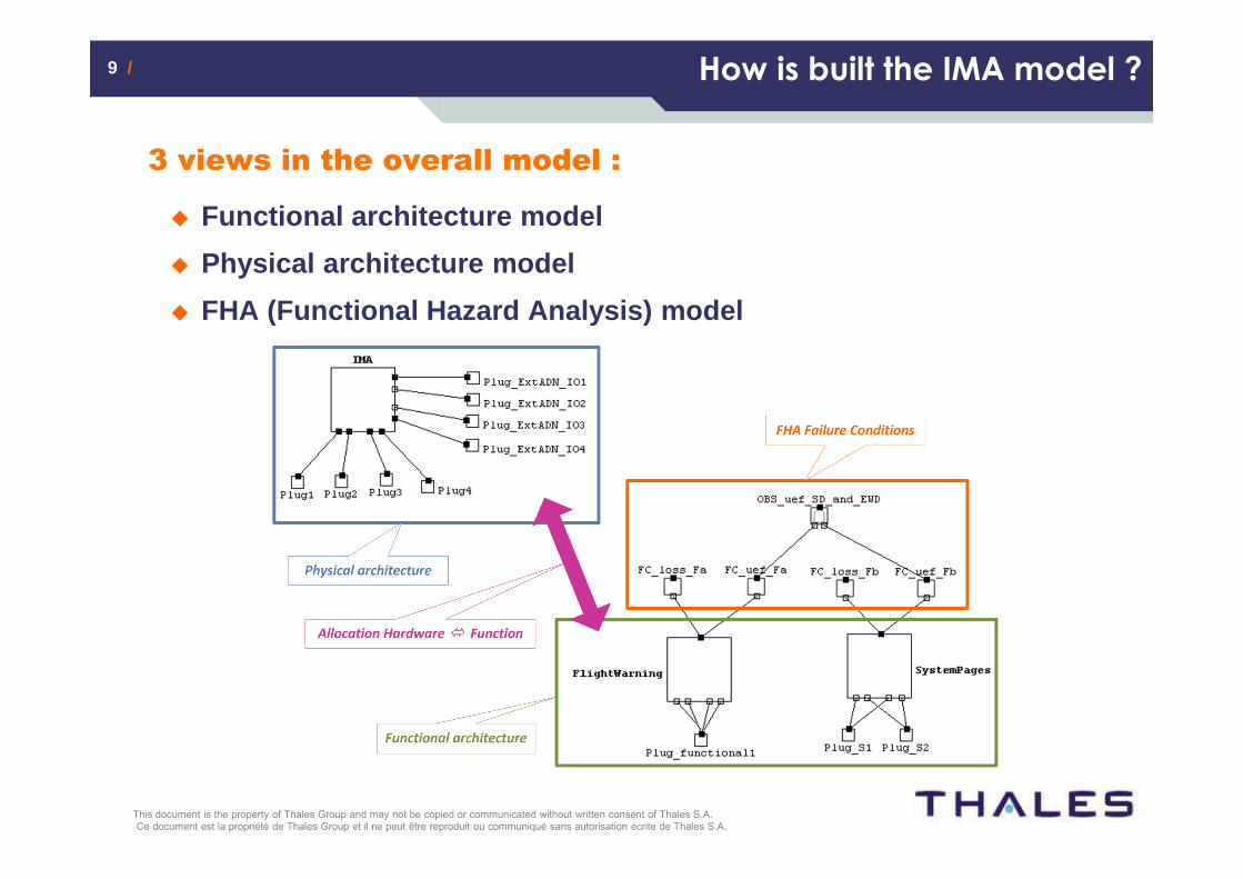
3 views in the overall model :
� Functional architecture model
� Physical architecture model
� FHA (Functional Hazard Analysis) model
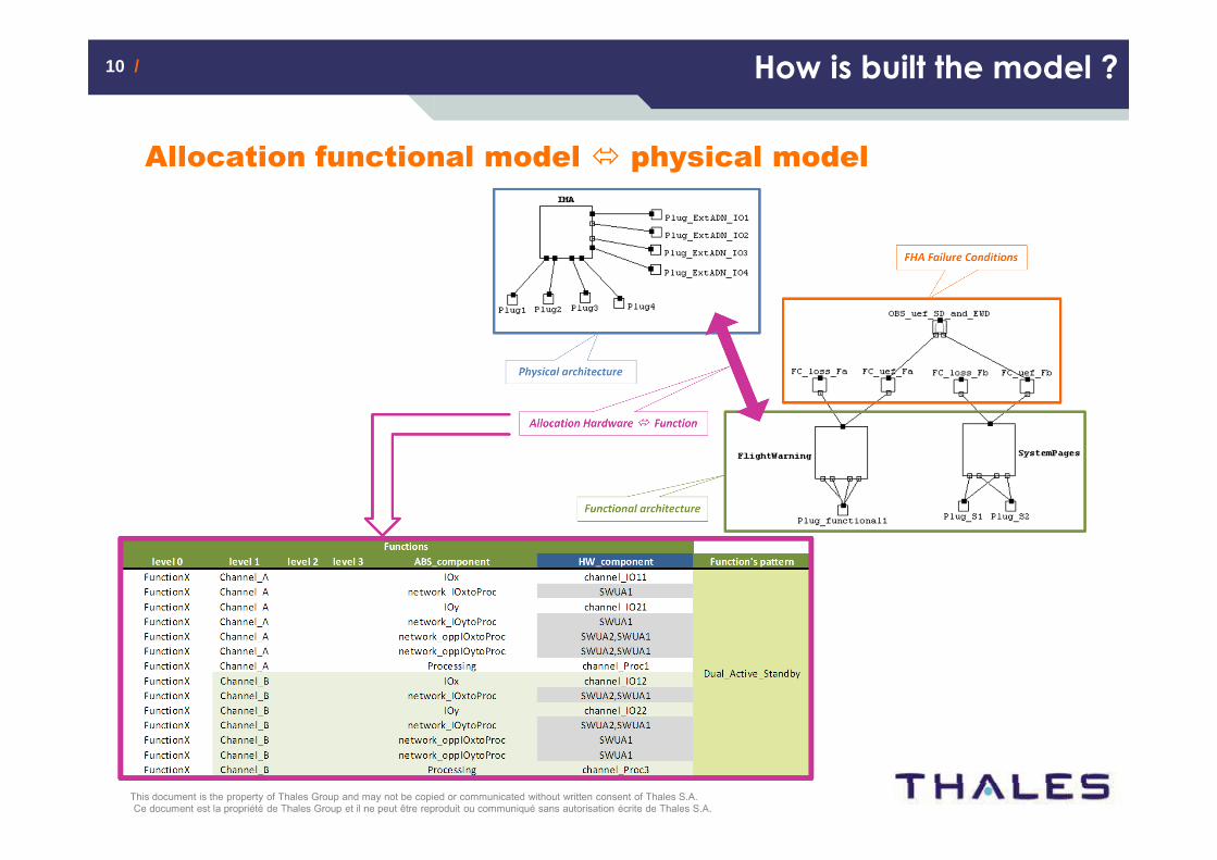
10 /10 / How is built the model ?
Allocation functional model � physical model

11 /11 / Objectives of IMA safety modeling
Two main objectives
� Identify weaknesses of proposed IMA architecture(s)
� Determine an optimal allocation :
� For the logical internal architecture of each function
� Choice of an fault-tolerant functional architecture (e.g. COM/MON, etc.)
� Depending on function’s FHA and safety performances of the physical architecture
� Specify quantitative requirements for the physical architecture
� Probability of failure occurrence for essential components
� Taking into account potential redundancies or monitoring at IMA physical level
� Depending on safety objectives associated to one channel
� For the allocation of functions to Hardware resources
� Taking into account each function’s logical architecture (e.g. COM/MON split on 2 IMA channels) and the number of IMA channels
� Depending on comprehensive A/C FHA taking into account potential functional combinations
� Problematic = 3 interdependent axes of architecture optimization
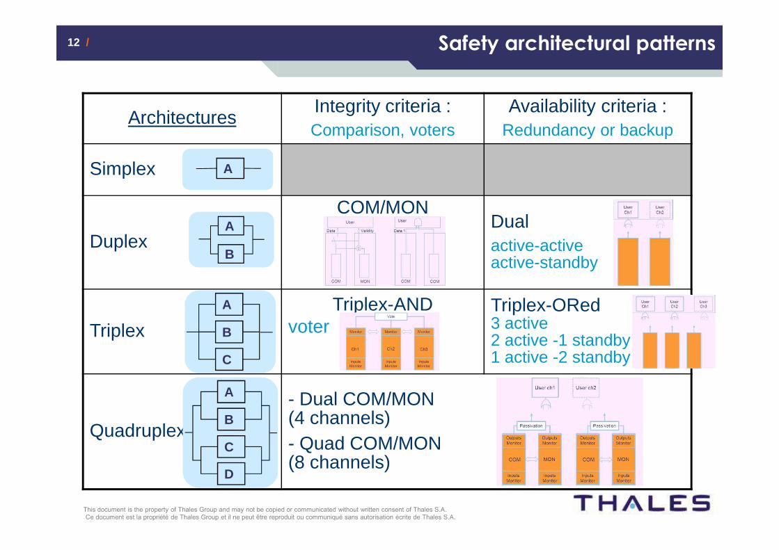
12 /12 /
ArchitecturesIntegrity criteria :Comparison, voters
Availability criteria :Redundancy or backup
Simplex
Duplex
COM/MONDualactive-activeactive-standby
TriplexTriplex-AND
voterTriplex-ORed3 active2 active -1 standby1 active -2 standby
Quadruplex
- Dual COM/MON (4 channels)- Quad COM/MON (8 channels)
A
A
B
A
B
C
A
B
C
D
Safety architectural patterns

13 /13 / Patterns associated to IMA model
Pattern modeling
� Breakdown :
� Internal components :
� Input / Output module(s)
� Processing module(s)
� Communication nodes between IO and processingmodules representing Virtual Link paths throughthe Avionics Data Network
� External Interfaces if relevant
� External Input(s) / Outputs(s)

14 /14 / Example of Altarica codeAltarica code for a basic node
Tabular description
State Automata
Altarica code
node Processing
flow
icone : [1, 3] : out ;
input : {ok,invalid,corrupted} : in ;
output : {ok,invalid,corrupted} : out ;
state
STATE : {SAFE,ERR,LOST} ;
event
loss, uef ;
init
STATE := SAFE ;
trans
STATE = SAFE |- uef -> STATE:=ERR;
STATE != LOST |- loss -> STATE:=LOST;
assert
output = (case{STATE = LOST : invalid,
STATE=ERR : corrupted,
else input)}; // component operative
icone = (case{STATE = LOST : 3,
STATE = ERR : 2,
else 1});
State(s) Domain / Type Initial value
STATE {SAFE,ERR,LOST} SAFE
Event(s) Guard New affectation Law
loss STATE != LOST STATE != LOST exponential(λloss)
error STATE = SAFE STATE = SAFE exponential(λuef)
Flow(s) Domain / Type Direction
input {ok,invalid,corrupted} in
output {ok,invalid,corrupted} out
output(s) Case(s) Value
STATE = SAFE and input = ok ok
STATE = SAFE and input = invalid invalid
STATE = SAFE and input = corrupted corrupted
STATE = LOST invalid
STATE = ERR corrupted
Assertion(s)
Transition(s)
output

15 /15 / IMA Failures propagation
Allocations physical items <-> functional items
� From the “physical” view to the “functional” view
Function #2
Failure Condition
Item F1' Item F1'’
Item F2
Function #1
Component C1
Physical architecture
Item P2
Item P1
Item P3
Dirac(0)
Virtual Status
Component C2
Functional architecture
FHA
Item F1' Item F1'’
Item F2
System
level
Allocation_ItemC2
Allocation_ItemP3
Strong synchronization
Failure Condition
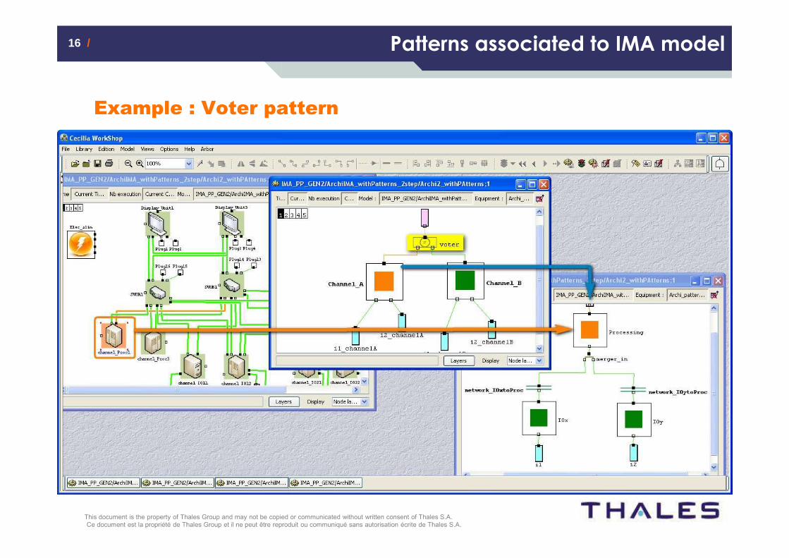
16 /16 / Patterns associated to IMA model
Example : Voter pattern
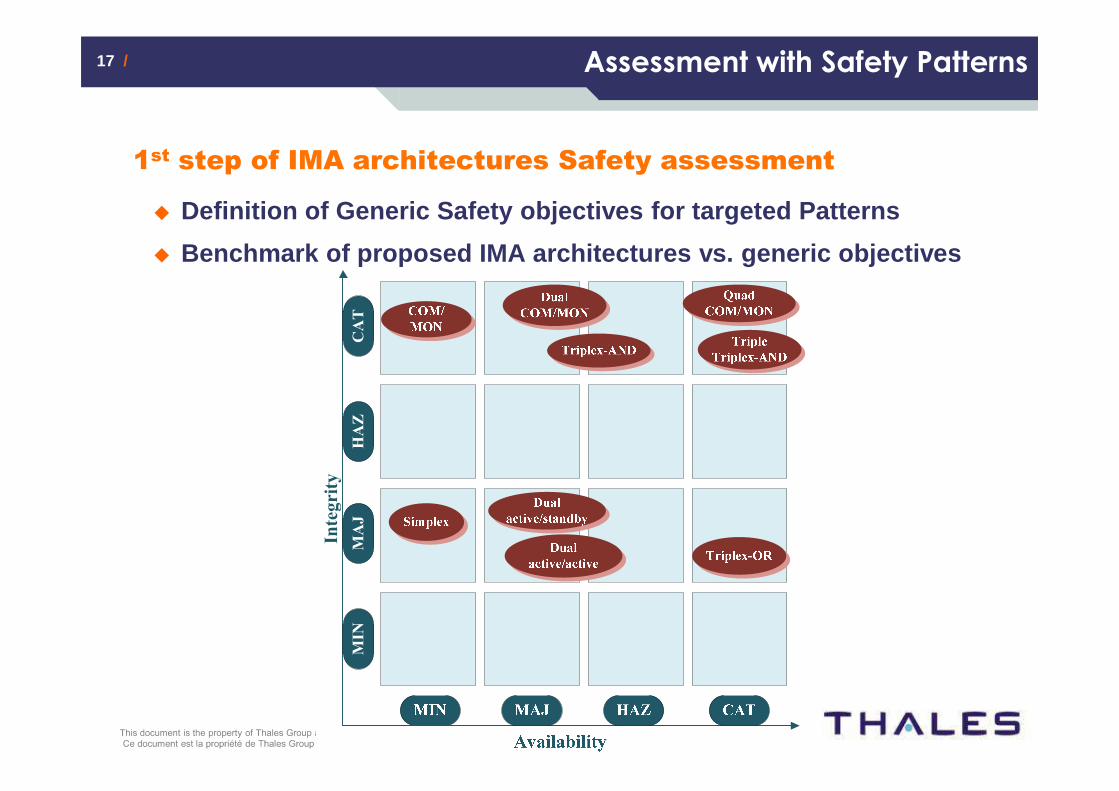
17 /17 / Assessment with Safety Patterns
1st step of IMA architectures Safety assessment
� Definition of Generic Safety objectives for targete d Patterns
� Benchmark of proposed IMA architectures vs. generic objectives
Integrity
MIN
MAJ
HAZ
CAT
18 /18 / Assessment with IMA full functional scope
2nd step of IMA architectures Safety assessment
� Definition of FHA
� Choice of best-suited pattern(s) for the function
� Depending on safety performances computed for each pattern
� Integration of each function in the overall model
� Dependencies with other functions if any
� FHA Failure Conditions (and in combination with other functions)
� Allocation(s) functional items to physical modules
� Assessment of targeted allocations vs. IMA architec tures

19 /19 / Plan
� Safety problematic of integrated and shared resourc es
� Modeling for Safety assessment in early validation
� Conclusion
20 /20 / Conclusion
Conclusion
� Model-Based approach� Improves modularity & reusability of safety analyses
� Supports complex, dynamic systems or large systems safety analyses
� Model handles common modes or cascading failures better than a static analysis
� Summary of the work
� Early Validation of different physical and functional architectures
� Use of safety architectural patterns helps to homogenize design of embedded functions
� Ease quick safety assessment through modular & incremental aspects
� Each view of the model may be refined during the V&V cycle
� The model may be iteratively extended to include new functions

21 /21 / Conclusion
Perspectives
� Model validation
� Validation of the allocation {functional item <-> hardware item} correctness
� Results completeness
� if an architecture is assessed Not OK vs. safety objectives :
� How to be sure that any other allocation will not be compliant ?
� if an architecture is assessed OK vs. safety objectives :
� How to be sure that all possible allocations are covered ?
� Results optimization
� How to determine an optimal allocation {functional item <-> hardware item} ?
� Reducing the required number of IMA hardware modules
� Taking into account additional allocation constraints specified in the functional view (independence, co-location, etc.)

22 /22 / Conclusion
Thank you for your attention