Embed Size (px)
Citation preview
Welcome
Environmental Advisory Board
Meeting
Robins Air Force BaseMay 2, 2013
1
Welcome and Program Introduction
Mr. Lex StokesEAB Installation Co-chair
2
Acronyms and Abbreviations
AFB – Air Force Base AS – Air Sparge bgs – below ground surface CAP – Corrective Action Plan CB – Chlorobenzene CAPE Team – Cape Environmental Management Inc and CH2M HILL
Constructors, Inc. DCE – Dicholoroethene DPT – Direct-push Technology ERD – Enhanced Reductive Dechlorination GA EPD – Georgia Environmental Protection Division ISCO – In-situ Chemical Oxidation MCL – Maximum Contaminant Level
3
Acronyms and Abbreviations
mg/L – milligram(s) per liter MNA – Monitored Natural Attenuation NFA – No Further Action PCE – Perchloroethene or Tetrachloroethene SVE – Soil Vapor Extraction SWMU – Solid Waste Management Unit TCE – Trichloroethene µg/L – microgram(s) per liter VOC – Volatile Organic Compound
4
DC034Horse Pasture Trench
Disposal Site(SWMU 36)
Update on Progress
Environmental Advisory Board
Dean Williamson, P.E.Technical Lead
CH2M HILL
5
May 2, 2013
Overview
Background Post-Excavation and Post-In-situ Chemical
Oxidation (ISCO) Subsurface Contamination Status
Previously Proposed Optimized Remedy Pre-Design Investigation Remedy Implementation Approach Path Forward
6
Background
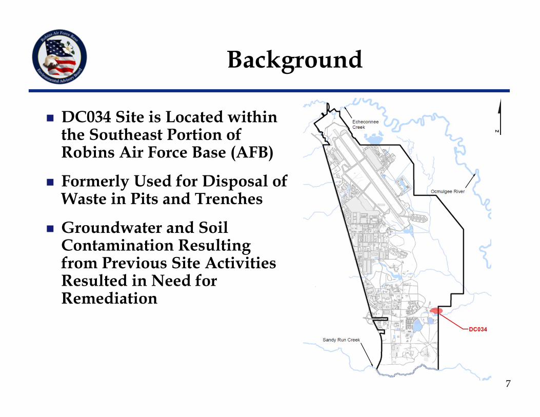
DC034 Site is Located within the Southeast Portion of Robins Air Force Base (AFB)
Formerly Used for Disposal of Waste in Pits and Trenches
Groundwater and Soil Contamination Resulting from Previous Site Activities Resulted in Need for Remediation
7
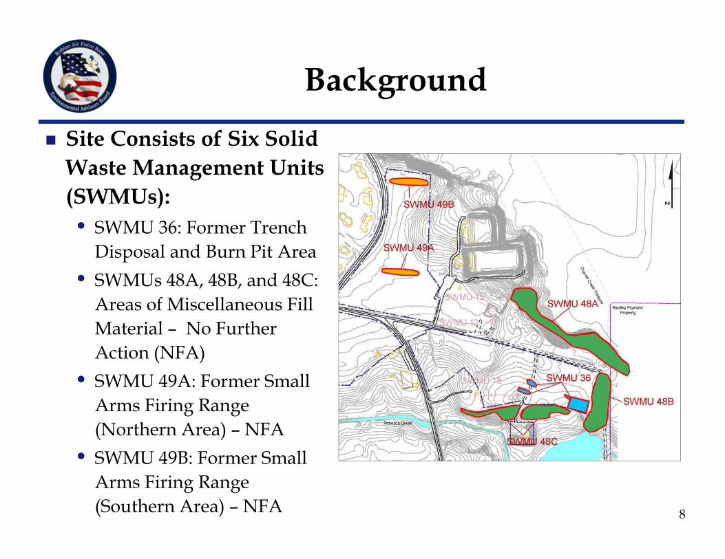
Site Consists of Six Solid Waste Management Units (SWMUs):• SWMU 36: Former Trench
Disposal and Burn Pit Area• SWMUs 48A, 48B, and 48C:
Areas of Miscellaneous Fill Material – No Further Action (NFA)
• SWMU 49A: Former Small Arms Firing Range (Northern Area) – NFA
• SWMU 49B: Former Small Arms Firing Range (Southern Area) – NFA 8
Background
Remedial Action in 2004 – Excavation, Stabilization, and Off-site Disposal of Contaminated Soil• Removed over 74,000 tons of contaminated soil from all six SWMUs• Excavated soils as deep as 27 feet below ground surface (bgs);
backfilled with clean soil
Georgia Environmental Protection Division (GA EPD) Granted NFA for Soils at all Six SWMUs in 2005
Since 2005, Groundwater Remedial Action has been Conducted at SWMU 36
Remedial Action in 2005 and 2006 – ISCO• 224 injection wells installed• Oxidants were Fenton’s reagent and sodium persulfate • Injected approximately 120,000 gallons of oxidant solution
9
Background
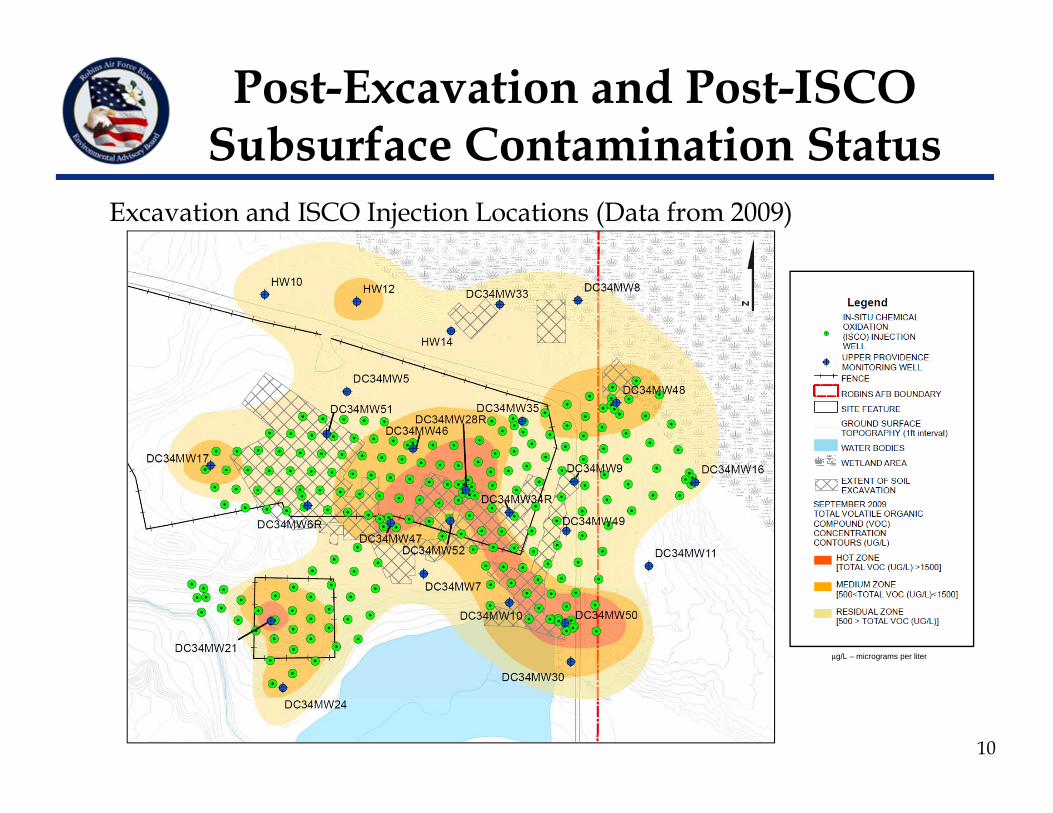
Excavation and ISCO Injection Locations (Data from 2009)
10
Post-Excavation and Post-ISCO Subsurface Contamination Status
μg/L – micrograms per liter
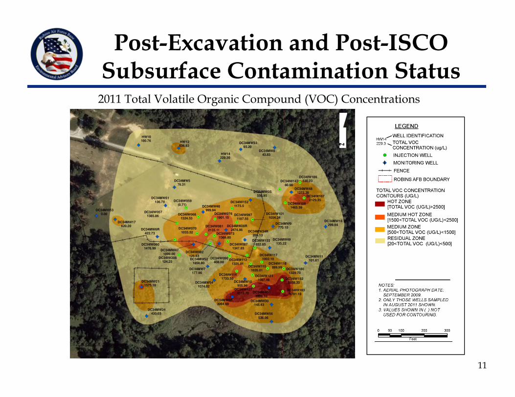
2011 Total Volatile Organic Compound (VOC) Concentrations
11
Post-Excavation and Post-ISCO Subsurface Contamination Status
Significant Contaminant Mass Reduction Achieved to Date through Soil Excavation
Groundwater Underlying Clay Layer at Site Contains Elevated Organic Compounds
Additional Remediation Required to Attenuate Remaining Groundwater Contamination
12
Post-Excavation and Post-ISCO Subsurface Contamination Status
Previously Proposed Optimized Remedy
13
Pre-design Characterization – Direct-push Technology (DPT) and Other Tools to Further Delineate Remaining Hot Spot Areas
Four Chlorobenzene (CB) Hot Spots – Excavate Soil, Off-site Disposal of Contaminated Soil, and Backfill with Clean Soil
Two Trichloroethene (TCE) Hot Spots – Mix Soil with Zero-valent Iron or Similar Amendment to Treat TCE In-situ
Plume Containment – Install Air Sparge (AS) Cutoff Trench inside Eastern Property Boundary to Control/Prevent Off-site Migration of Impacted Groundwater
Revisiting Previously Proposed Optimized Remedy Based on New Data
Pre-Design Investigation
Phase 1 (November 2012)• Objective – Further delineate groundwater hot spots
and investigate upgradient edge of groundwater hot spots
• Activities Conducted – Groundwater samples were collected from 70 existing injection wells within the six target treatment areas
14
Phase 2 (December 2012)• Objective
─ Assess current status of contamination source in soil ─ Further delineate groundwater and soil hot spots─ Collect lithological information along proposed AS trench area
• Activities Conducted─ Collected 12 groundwater samples from existing injection wells;
collected 17 groundwater samples from seven DPT borings; field-screened 38 groundwater samples from 13 DPT locations
─ Installed seven soil borings along the AS cutoff trench line; collected groundwater samples below the clay layer from two locations in this area
─ Collected nine soil samples from five DPT borings 15
Pre-Design Investigation
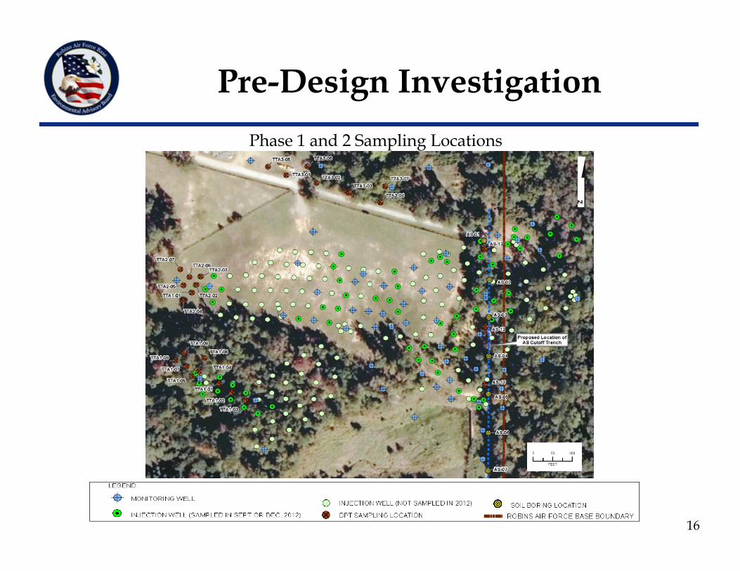
Phase 1 and 2 Sampling Locations
16
Pre-Design Investigation
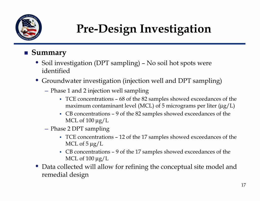
Summary• Soil investigation (DPT sampling) – No soil hot spots were
identified• Groundwater investigation (injection well and DPT sampling)
─ Phase 1 and 2 injection well sampling TCE concentrations – 68 of the 82 samples showed exceedances of the
maximum contaminant level (MCL) of 5 micrograms per liter (μg/L) CB concentrations – 9 of the 82 samples showed exceedances of the
MCL of 100 μg/L ─ Phase 2 DPT sampling
TCE concentrations – 12 of the 17 samples showed exceedances of the MCL of 5 μg/L
CB concentrations – 9 of the 17 samples showed exceedances of the MCL of 100 μg/L
• Data collected will allow for refining the conceptual site model and remedial design
17
Pre-Design Investigation
Shift Focus of Groundwater Corrective Action from the Treatment of Lower Clay Soils to In-situ Treatment of Site Groundwater
Evaluate In-situ Groundwater Remediation Technologies, including: • In-situ bioremediation technologies
─ Enhanced reductive dechlorination (ERD) for chloroethenes─ Aerobic bioremediation for CB
• Alternate forms of ISCO Implement AS/Soil Vapor Extraction (SVE) Cutoff Trench
near Eastern Property Boundary to Mitigate Off-site Contaminant Migration
Implement Additional Focused Field Activities to Resolve Remaining Uncertainties Regarding Conceptual Site Model
Optimize Remediation System Based on New Findings
Remedy Implementation Approach
18
Path Forward
Submit Corrective Action Plan (CAP) to GA EPD(May 2013)
Submit Remedial Design/Remedial Action Work Plan (June 2013)
Field Implementation of Remedial Action(September – December 2013)
Treatment Progress Monitoring and Monitoring Well Network Optimization (After Field Implementation)
19
SWMU 20Greater Base Industrial AreaChlorinated Solvent Plume
Update on Progress
Environmental Advisory Board
David L. Fortune, P.E.Technical Lead
CAPE Environmental Management Inc.
20
May 2, 2013
Overview
Background Description of Current Remedy Proposed Optimized Remedy Summary of 90 Percent Design Path Forward
21
22
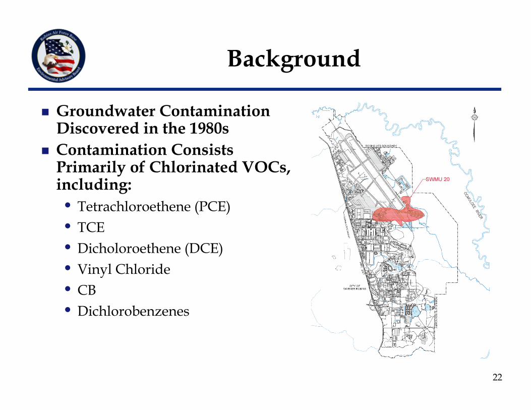
Background
Groundwater Contamination Discovered in the 1980s
Contamination Consists Primarily of Chlorinated VOCs, including:• Tetrachloroethene (PCE)• TCE• Dicholoroethene (DCE)• Vinyl Chloride• CB• Dichlorobenzenes
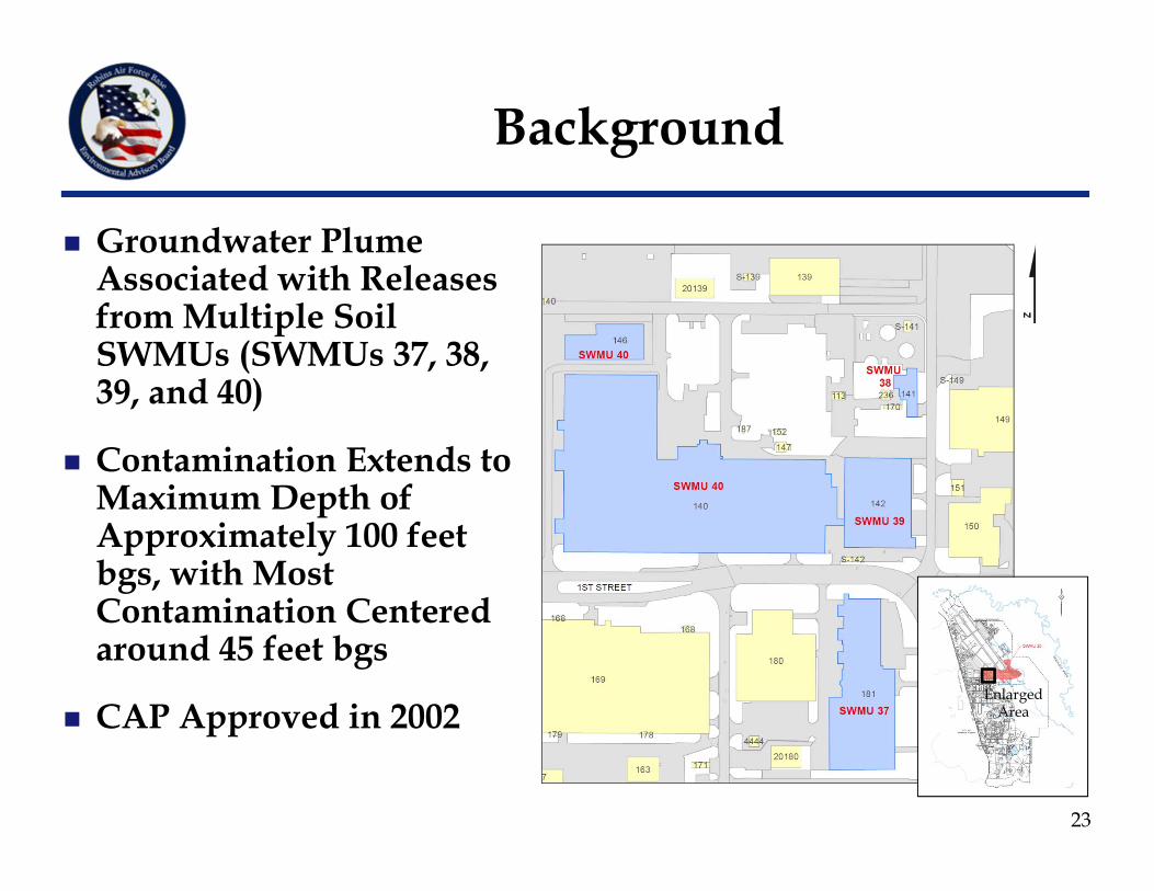
Groundwater Plume Associated with Releases from Multiple Soil SWMUs (SWMUs 37, 38, 39, and 40)
Contamination Extends to Maximum Depth of Approximately 100 feet bgs, with Most Contamination Centered around 45 feet bgs
CAP Approved in 2002
23
Background
EnlargedArea
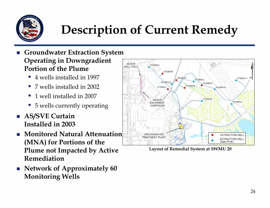
Groundwater Extraction System Operating in Downgradient Portion of the Plume• 4 wells installed in 1997• 7 wells installed in 2002• 1 well installed in 2007• 5 wells currently operating
AS/SVE Curtain Installed in 2003
Monitored Natural Attenuation (MNA) for Portions of the Plume not Impacted by Active Remediation
Network of Approximately 60 Monitoring Wells
Layout of Remedial System at SWMU 20
Description of Current Remedy
24
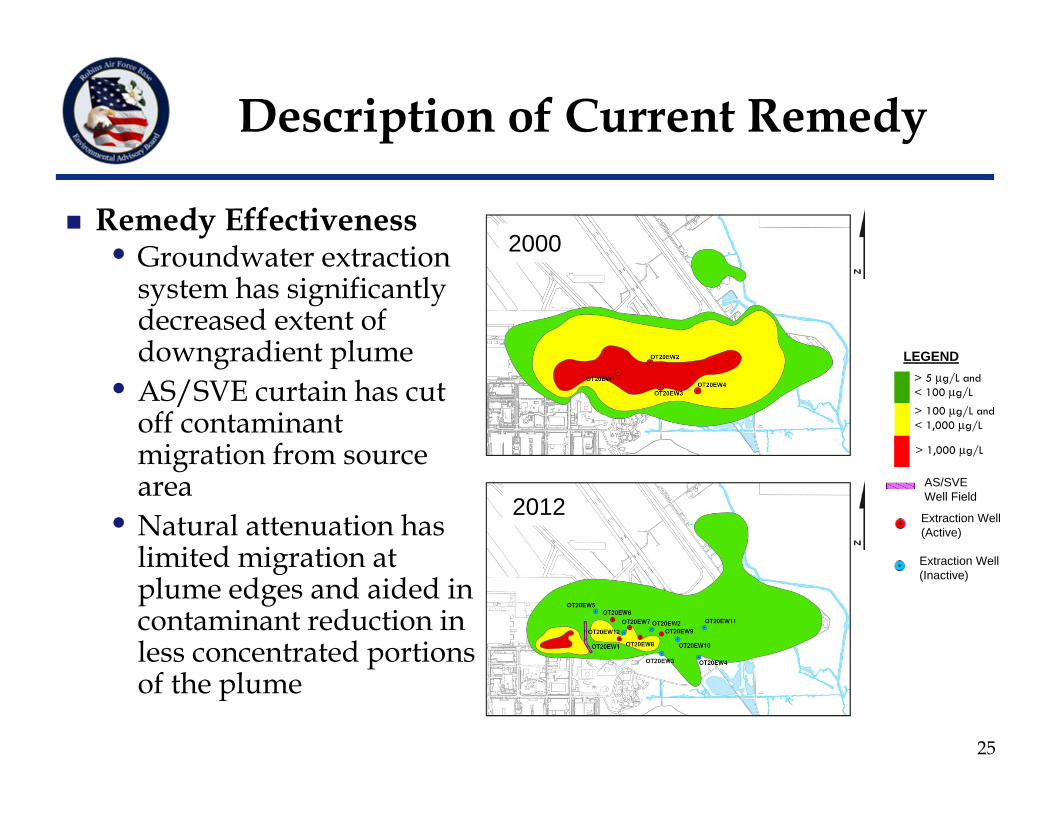
Remedy Effectiveness• Groundwater extraction
system has significantly decreased extent of downgradient plume
• AS/SVE curtain has cut off contaminant migration from source area
• Natural attenuation has limited migration at plume edges and aided in contaminant reduction in less concentrated portions of the plume
Description of Current Remedy
> 100 μg/L and< 1,000 μg/L
> 5 μg/L and < 100 μg/L
> 1,000 μg/L
LEGEND
AS/SVE Well Field
2000
Extraction Well(Active)
Extraction Well(Inactive)
25
2012
26
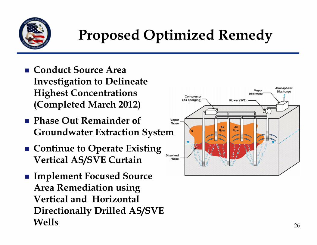
Proposed Optimized Remedy
Conduct Source Area Investigation to Delineate Highest Concentrations (Completed March 2012)
Phase Out Remainder of Groundwater Extraction System
Continue to Operate Existing Vertical AS/SVE Curtain
Implement Focused Source Area Remediation using Vertical and Horizontal Directionally Drilled AS/SVE Wells
Conceptual Design included with CAP Addendum – Currently in Review with GA EPD
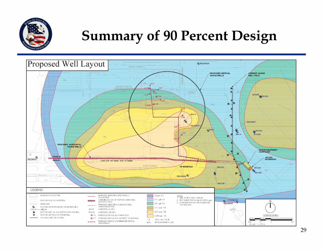
Changes to Conceptual Design:• Original design included two horizontal AS/SVE well pairs (northern
and southern)• Initial utility survey determined that there were too many buried
utilities to install the northern SVE well, so it was replaced with a cluster of 8 vertical AS wells and 6 vertical SVE wells
SVE Wells are Designed to Capture 120 Percent of Injected Air Horizontal/Vertical AS Wells Installed to a Depth of 60 feet bgs Horizontal/Vertical SVE Wells Installed to a Depth of 9 feet bgs Currently Finalizing 100 Percent Design and Construction Work
Plan
27
Proposed Optimized Remedy
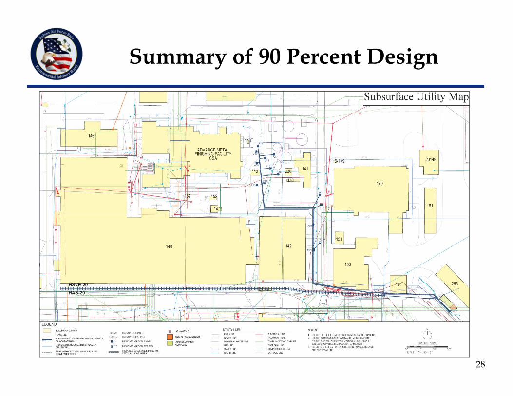
Summary of 90 Percent Design
28
Summary of 90 Percent Design
29
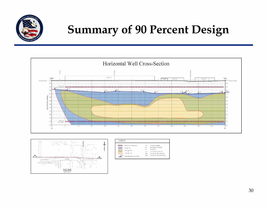
Summary of 90 Percent Design
30
31
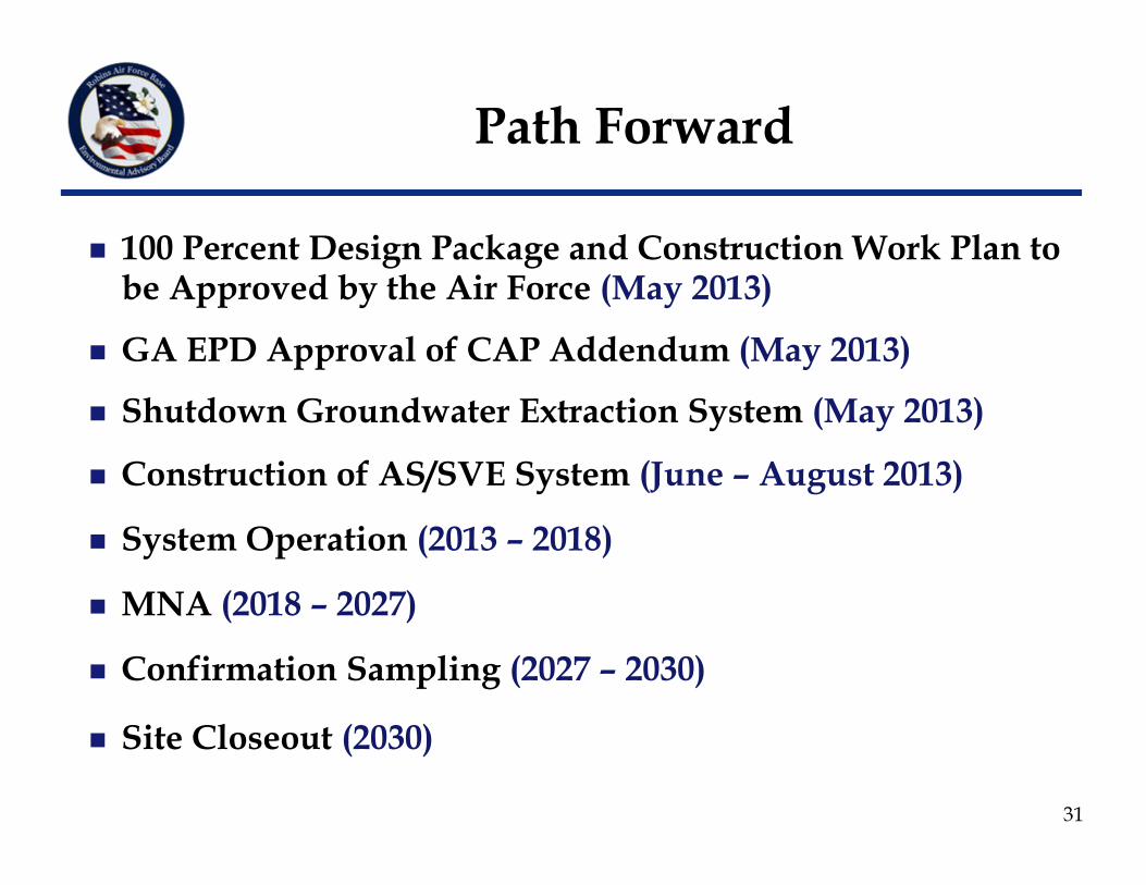
100 Percent Design Package and Construction Work Plan to be Approved by the Air Force (May 2013)
GA EPD Approval of CAP Addendum (May 2013)
Shutdown Groundwater Extraction System (May 2013)
Construction of AS/SVE System (June – August 2013)
System Operation (2013 – 2018)
MNA (2018 – 2027)
Confirmation Sampling (2027 – 2030)
Site Closeout (2030)
Path Forward
New Businessand
Program Closing
Mr. Lex StokesEAB Installation Co-chair
32
Next EAB Meeting
Thursday, 1 August 2013
33
Please…Complete the meeting evaluation and feedback form and leave at your seat
Leave your name tag at the sign-in table for the next meeting
Thank you!34