Embed Size (px)
Citation preview

Be Strong.™
E916 and EV916 Service Manual
PN 40478A Rev A (11/2005)

2
This manual is intended for authorized Nautilus® or Nautilus® certified service personnel and not for the consumer. There are no user serviceable parts. Servicing of the Nautilus® Commercial Series Elliptical by other than authorized Nautilus® or Nautilus® certified service personnel may result in voiding of the warranty.
If you are a consumer and require technical support to resolve a problem with your Nautilus® Commercial Series Elliptical, please call Nautilus® Customer Service at 800-864-1270 (USA) or +41 460 77 88 (outside USA).
Important—Please Read

3Nautilus® Commerical Series Elliptical Service Manual
Important Safety Information..................................................................................................................5
Product SpecificationsEV916 Elliptical Trainer...............................................................................................................................................6
E916 Elliptical Trainer.................................................................................................................................................7
Console CodesOverview ..................................................................................................................................................................11
Defaults ....................................................................................................................................................................11
Customize .................................................................................................................................................................11
Machine Status ........................................................................................................................................................12
Diagnostics ...............................................................................................................................................................13
Maintenance Logs ....................................................................................................................................................14
Machine Configuration .............................................................................................................................................16
Wiring SchematicsEV916 Top Level Wiring Diagram ............................................................................................................................18
EV916 Power and Alternator Wiring Diagram .........................................................................................................19
E916 Console Heart Rate Wiring Diagram ..............................................................................................................20
E916 Main Power Wiring Diagram ..........................................................................................................................21
Assembly Illustrations
Service Parts List - EV916 .........................................................................................................................................25
Cable Connections - EV916 .......................................................................................................................................31
Assembly Drawings Overview - EV916 ....................................................................................................................33
Cam Covers (Pods) and Front Knuckle Covers ......................................................................................................33
Swing Arm / Foot Link Assembly Junction ..........................................................................................................34
Front Mast Assembly / Main Frame Junction .....................................................................................................34
Drive Train Cover Assembly ..................................................................................................................................35
Drive Train Assembly w/ Main Power Assembly .................................................................................................35
Crank Cover and Crank Assembly ........................................................................................................................36
Rear Drive Assembly ............................................................................................................................................37
Alternator Assembly .............................................................................................................................................38
Foot Link Assembly (Left) ...................................................................................................................................... 38
Foot Link Assembly (Right) .................................................................................................................................... 39
Table of Contents

4
Dependency Cover (Cupholder) Assembly ........................................................................................................... 39
Swing Arm Assembly ........................................................................................................................................... 40
Dependency Link Assembly ................................................................................................................................. 41
Dynamic (Upper Body) Handles Assembly ........................................................................................................... 42
Fixed Handle (T-Bar) Assembly ............................................................................................................................ 42
Console Mount ..................................................................................................................................................... 43
Service Parts List - E916 ......................................................................................................................................... 44
Cable Connections - E916 ....................................................................................................................................... 53
Assembly Drawings Overview - E916 ..................................................................................................................... 54
Cam Covers (Pods) and Front Knuckle Covers ...................................................................................................... 54
Swing Arm / Foot Link Assembly Junction ........................................................................................................... 55
Front Mast Assembly / Main Frame Junction ...................................................................................................... 56
Drive Train Cover Assembly .................................................................................................................................. 56
Crank Cover and Drive Train Assembly ................................................................................................................. 57
Crank Arm Assembly ............................................................................................................................................. 57
Eccentric Crank Arm Assembly (detail) ................................................................................................................. 58
Rear Drive Assembly ............................................................................................................................................. 59
Alternator Assembly ............................................................................................................................................. 60
Connecting Arm Assembly .................................................................................................................................... 60
Foot Link Assembly (Right) .................................................................................................................................... 61
Foot Link Assembly (Left) ...................................................................................................................................... 61
Swing Arm Cover and Cupholder .......................................................................................................................... 62
Swing Arm Assembly ............................................................................................................................................ 62
Dynamic Handles and Polar Sensor ...................................................................................................................... 63
Dynamic (Upper Body) Handles and Grips ............................................................................................................ 64
Fixed (T-Bar) Handle Assembly ............................................................................................................................. 64
Console Support .................................................................................................................................................... 65
AppendixesRequired Tools ..........................................................................................................................................................68
International Power Plug Configurations .................................................................................................................68
Warranty Information ......................................................................................................................................................69Contact Numbers ............................................................................................................................................................70
Contents
5Nautilus® Commerical Series Elliptical Service Manual
IMPORTANT SAFETY INFORMATION: SAVE THESE INSTRUCTIONS
The following definition applies to the word “Warning” found throughout this guide:
WARNING - Used to call attention to POTENTIAL hazards that could result in personal injury or loss of life.
Read All Instructions
THIS SYMBOL APPEARING THROUGHOUT THIS MANUAL MEANS PAY ATTENTION! BE ALERT! YOUR SAFETY IS INVOLVED!
� � � � � � �
� � � � � � � � �
� � � � � �
�������������������������
� � � � � � �
1. Read, understand and carefully follow all warnings, instructions and procedures in this manual. Failure to do so can produce a serious electrical shock hazard or other serious injury.
2. The external power supply should always be unplugged from the AC wall outlet before removing or installing parts. Never make adjustments or repairs while an exercise program is in progress.
3. Close supervision is necessary whenever the machine is being used or serviced whenever children, invalids, or disabled persons are in the vicinity.
4. Keep hands away from all moving parts. Keep feet on the pedals while exercising or testing the machine.
5. Do not operate the machine with the side covers removed, or outdoors.
6. Use this machine only for its intended use as described in this Manual. Do not use parts, attachments, or accessories other than those provided by Nautilus, Inc.
7. Do not use the external power supply if it has a damaged cord or plug, it is not working properly, if it has been dropped or damaged, or dropped in water. Contact our Technical Service Department to arrange for the return of damaged parts.
8. To avoid potential safety and electrical problems, replace with manufacturer’s specified parts only.
9. Connect the external power supply to a properly grounded AC wall outlet.
10. Keep all cords away from heated surfaces.
11. To disconnect the external power supply, remove the plug from the AC wall outlet.
12. Do not let liquid enter the console. If liquid does enter the console, the console must be inspected and tested for safety by an approved technician before it can be used again.
13. Never drop or insert any object into any opening on the machine.
14. Keep the area underneath and around the machine clear.
15. Do not operate where aerosol (spray) products are being used.
16. Always wear insulated gloves when handling batteries.
17. Do not crush, incinerate, or dismantle the battery.
18. The safety level provided by the design of this equipment can only be maintained when the equipment is regularly examined for damage and wear. Inoperable components should be replaced immediately or the equipment be put out of use until it is repaired.
19. Failure to follow the guidelines may compromise the effectiveness of the exercise experience, expose you (and possibly others) to injury, and reduce the longevity of the machine. Follow all training instructions listed in the manual and/or on the machine.
Failure to follow the conditions set forth below shall limit, to the extent allowed by law, Nautilus, Inc. responsibility for the safety, reliability, and performance of this equipment.
• The operator manual must be read in full by each owner and trainer before the product is first used. Each user must be instructed in the proper use of the elliptical and its accessories.
• The equipment must be used in accordance with the instructions for use.
• Only Nautilus-trained or Nautilus-authorized personnel should carry out assembly operations, extensions, readjustments, modifications, or repairs.
• For further information or instruction on use, maintenance or specifications, please contact your Authorized Nautilus Fitness Dealer or Service Technician.
THE ELECTROLYTE CONTAINS SULFURIC ACID, WHICH CAN CAUSE SERIOUS DAMAGE TO EYES AND SKIN. SHOULD
THIS OCCUR, FLUSH PROFUSELY WITH WATER AND SEEK MEDICAL ATTENTION.
� � � � � � �
� � � � � � � � �
� � � � � �
�������������������������
� � � � � � �

6
Ele
ctric
al
PowerCordless, or 108-132VAC, 50/60 Hz, 20 watts maximum (operation with charger connected)
Battery Type 6VDC sealed lead-acid
Battery Charge Time 8 hours to full charge, starting with discharged battery
Display C51 blue/white LCD with backlightTactile membrane keypanel
Phy
sica
l
Length 94 in. (239 cm)
Width 28 in. (71 cm)
Height 62 in. (157.5 cm)
Weight 350 lb. (147 kg)
Max User Weight Supported 400 lb. (181 kg)
Belt(s) Two: 10-groove drive belt and 6-groove alternator belt
Func
tiona
lity
Ellipse Stride Length Dynamically variable up to 30” (76 cm)
Number of Functions
Ten: Heart rate, elapsed time, calories burned, calories burned per hour, watts, METS, resistance level, rpm, distance, and workout profile
Heart Rate Monitoring Integrated heat rate monitoring system with polar-compatible wireless and contact HR
Workout Programs
Twelve: Quick Start, Manual, Fat Burner, Calorie Burner, Intervals, HR Zone Trainer, multi-stage Fit Test’. Custom Intervals, HR Intervals, Random Play
Resistance Range Twenty: 20 watts (level 1, 20 rpm) to 300 watts (level 20, 100 rpm)
Language Options English, German, French, Spanish, Italian, Dutch, Portuguese
C-Safe Compatible Level 2 compatible. Owner/manager will be able to customize console.
Env
ironm
enta
l Operating Temperature 50–90 oF (10–32 oC)
Storage Temperature -25–50 oC
Operating Humidity (non-condensing) 3–95% relative humidity
Storage Humidty (non-condensing) 3–95% relative humidity
Specifications - EV916 Elliptical Trainer with MyStride® Technology
7Nautilus® Commerical Series Elliptical Service Manual
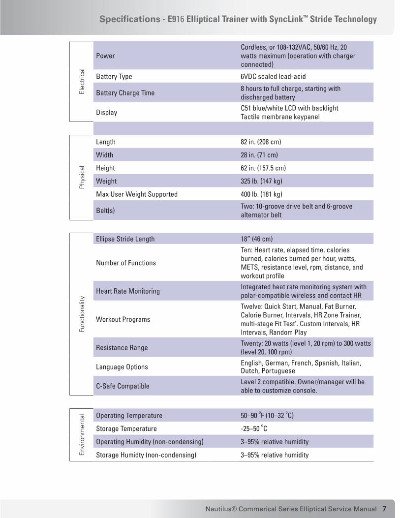
Specifications - E916 Elliptical Trainer with SyncLink™ Stride Technology
Ele
ctric
al
PowerCordless, or 108-132VAC, 50/60 Hz, 20 watts maximum (operation with charger connected)
Battery Type 6VDC sealed lead-acid
Battery Charge Time 8 hours to full charge, starting with discharged battery
Display C51 blue/white LCD with backlightTactile membrane keypanel
Phy
sica
l
Length 82 in. (208 cm)
Width 28 in. (71 cm)
Height 62 in. (157.5 cm)
Weight 325 lb. (147 kg)
Max User Weight Supported 400 lb. (181 kg)
Belt(s) Two: 10-groove drive belt and 6-groove alternator belt
Func
tiona
lity
Ellipse Stride Length 18” (46 cm)
Number of Functions
Ten: Heart rate, elapsed time, calories burned, calories burned per hour, watts, METS, resistance level, rpm, distance, and workout profile
Heart Rate Monitoring Integrated heat rate monitoring system with polar-compatible wireless and contact HR
Workout Programs
Twelve: Quick Start, Manual, Fat Burner, Calorie Burner, Intervals, HR Zone Trainer, multi-stage Fit Test’. Custom Intervals, HR Intervals, Random Play
Resistance Range Twenty: 20 watts (level 1, 20 rpm) to 300 watts (level 20, 100 rpm)
Language Options English, German, French, Spanish, Italian, Dutch, Portuguese
C-Safe Compatible Level 2 compatible. Owner/manager will be able to customize console.
Env
ironm
enta
l Operating Temperature 50–90 oF (10–32 oC)
Storage Temperature -25–50 oC
Operating Humidity (non-condensing) 3–95% relative humidity
Storage Humidty (non-condensing) 3–95% relative humidity

8

9Nautilus® Commerical Series Elliptical Service Manual
Console Codes1
Contents
Overview ..................................................................................................... 11
Defaults ....................................................................................................... 11
Customize .................................................................................................... 11
Machine Status ........................................................................................... 12
Diagnostics ................................................................................................. 13
Maintenance Logs ...................................................................................... 13
Reset Maintenance Hours ...................................................................... 14
Error Log ................................................................................................. 14
Machine Configuration ............................................................................... 15

10

11Nautilus® Commerical Series Elliptical Service Manual
OverviewTo enter a Service Mode, the unit must be in IDLE DISPLAY state or an ERROR. The service screens cannot be entered during a workout, paused or in a WARNING state. (If the unit is in a Warning state, you must press [CLEAR] before entering the Service Modes.) To access the console codes, press the Level Up button (▲), the group number code, and [ENTER]. Then use the arrow buttons to scroll through the menu options for each group. The procedures are outlined in the tables below.
There are six groups of Service Mode console codes: Defaults (codes starting with 2), Customize (codes starting with 3), Machine Status (codes starting with 4), Diagnostics (codes starting with 6), Maintenance Logs (codes starting with 7), and Change Machine (codes starting with 8). Each group of codes is defined below.
DefaultsYou can customize several workout parameters on the E916/EV916 Elliptical with default values to conform to your individual requirements, including:• % target heartrate (10-90%) • age (10-99) • workout time (5-99 min) • workout level (1-20)• weight (50-400 lbs. or 25-180 kg)
Refer to the following table to scan through and customize the settings: Table 2–1. Defaults
Step No. Press Keys Display (What you will see)
1 ▲, 2, ENTER DEFAULTS
2 ▼ or ▲ CHR PERCENT, AGE, TIME, LEVEL, WEIGHT
3 ENTER Selected choice
4 ▼ or ▲ (or numeric keypad) Default value changes
5 ENTER DEFAULTS
6 CLEAR SELECT WORKOUT
CustomizeYou can customize several console settings on the E916/EV916 Elliptical with default values to conform to your individual requirements, including:• resetting all configurable settings to factory defaults (see below)
• adjusting lower screen contrast (0-15)
• adjusting upper screen contrast (0-15)
• console language
• choosing type of heartrate inputs (description below)
Customization

12
• change units (USA units or metric units)
• cooldown time (1-10 min)
• maximum time limit (10-99 min or OFF)
Refer to the following table to scan through and customize the settings: Table 2–2. Customize
Step No. Press Keys Display (What you will see)
1 ▲, 3, ENTER CUSTOMIZE
2 ▼ or ▲ SET DEFAULTS, CONTRAST ADJ LOWER, CONTRAST ADJ UPPER, LANGUAGE, SELECT STATS*, HR INPUTS, CHANGE UNITS, COOL DOWN, MAX TIME LIMIT
3 ENTER Selected choice
4 ▼ or ▲ (or numeeric keypad) Default value changes
5 ENTER CUSTOMIZE
6 CLEAR SELECT WORKOUT
*The SELECT STATS menu display option is not active for the E916 and EV916. Set Defaults – resets the machine to the factory defaults for all configurable values. Please note that selecting this option will require the machine to be reconfigured (see Change Machine section).
NOTE: All error and history counter data (Maint Hours, Distance, Workouts, Run Hours, Error Log, and QA ID Number) will be lost if Set Defaults is selected.
HR Inputs – enables the various heart rate inputs that can be used. Heart rate configurations include: Locked Inputs (both heart rate monitors are read until it detects a valid signal to lock on, at which point the other HR inputs are ignored), HR PRGM OFF, Both HR OFF, Hand Only, Telemetry Only, and Either Input (if one input is lost, then the other input may become active).
Change Units - changes all displayed data (service information and user data) to the selected units. Units are: Miles or Kilometers, MilesPerHour or KilometersPerHour, Pounds (LB) or Kilograms (KG), MinutesPerMile or MinutesPerKM.
Machine StatusUse the machine status codes to view maintenance information such as:• maintenance hours
• machine type (Elliptical)
• console software version
• distance traveled
• number of workouts
• machine run-time hours
Machine Status

13Nautilus® Commerical Series Elliptical Service Manual
Refer to the following table to scan through and customize the settings:
Table 2–3. Machine Status
Step No. Press Keys Display (What you will see)
1 ▲, 4, ENTER MACHINE STATUS
2 ▼ or ▲ MAINT HOURS, ELLIPTICAL [or other], CONS, DISTANCE, WORKOUTS, RUN HOURS
3 CLEAR SELECT WORKOUT
Maint Hours – displays the number of hours (incremented every hour) the machine has been running. The start value is set under the Maintenance Logs service screen. (The start value can be set to any value—e.g. if the service tech had entered 100 in the Maintenance Logs service screen and there was 1 hour of running time on the machine, the value under this Maint Hours screen would read 101).
Machine Type – should display Elliptical. “NTM Config REQD” appears on the console if the software has been updated on the machine or the machine froze up and the power had to be cycled. The message also appears when the console assembly has been replaced and no configuration established. Configuring the machine will eliminate this message (see the table “Machine Configuration”).
Distance – displays the total distance in miles (or kilometers) of machine operation. This value is auto-incremented every 1/100th or 1/10th unit, depending on how many miles/km have accrued.
Workouts – displays the total number of workouts performed on the machine. This value is auto-incremented only if the user enters a workout and either completes the workout or presses the [STOP] key twice.
Run Hours – displays the total number of hours on the machine.
NOTE: The R&D options (codes starting with 5) are not used for servicing machines. Do not change these settings. If an R&D setting is inadvertently changed, it will reset when the machine is powered off and then back on.
DiagnosticsUse diagnostic codes to test various components of the machine such as the:• tachometer
• alternator
• I/O
• sensor (for EV9.16 only)
• serial ports
• keypad
• display
Diagnostics

14
Refer to the following table to scan through the diagnostic tests and view diagnostic information:Table 2–4. Diagnostics
Step No. Press Keys Display (What you will see)
1 ▲, 6, ENTER DIAGNOSTICS
2 ▼ or ▲ TACH TEST, ALT TEST, I/O TEST, A SENSOR B, SERIAL PORTS, KEY TEST, DISPLAY TEST
3 ENTER Selected choice
4 CLEAR DIAGNOSTICS
5 CLEAR SELECT WORKOUT
Tach Test – performs a tachometer test. On the left hand side of the display the target rate of 2000 rpm is displayed. On the right hand side of the display the actual rpm is displayed. If the actual rpm is above the target rate, then the alternator field turns on (the level increases). If the actual rpm is below the target rate, then the alternator field shuts off (the level decreases).
Alt Test – performs an alternator test. By pressing the level up key, the alternator field will turn on and the steps will become harder to rotate. By pressing the level down key, the alternator field will turn off and the steps will become easier to rotate.
I/O Test – The AUX and B+ values represent the current and voltage delivered from the alternator respectively. AUX is scaled by 1000 and B+ is scaled by 300. These values will increase with the speed of the alternator (note that both values will reach 0 if the alternator is left at rest). The “---” string is displayed at all times since the ellipticals do not require a magnetic key.
A Sensor B – is used only on the EV9.16. The A Sensor B diagnostic screen ensures the optical detector is functional. The A value is displayed on the left hand side of the upper display (B is not used on the EV9.16). Under normal conditions, the A value should toggle between the “0” and “1”.
Serial Ports - tests the serial ports (UARTS) for proper functionality. The tech can choose from either the CSAFE-1 Loopback or TM Loopback tests. Both of these tests result in PASS or FAIL. Please note that a null modem must be used to perform these tests.
Key Test - tests all of the user interface keys. Once a key is pressed, its value will show up on the display screen. After all keys have been pressed and are functional, a PASS message appears on the display.
Display Test - will test all segments on both the top and bottom displays.
Maintenance LogsThe MAINTENANCE LOGS settings allow you to view the quality assurance data, the machine’s error log, and reset the time between service and maintenance calls.
Maintenance Logs
15Nautilus® Commerical Series Elliptical Service Manual
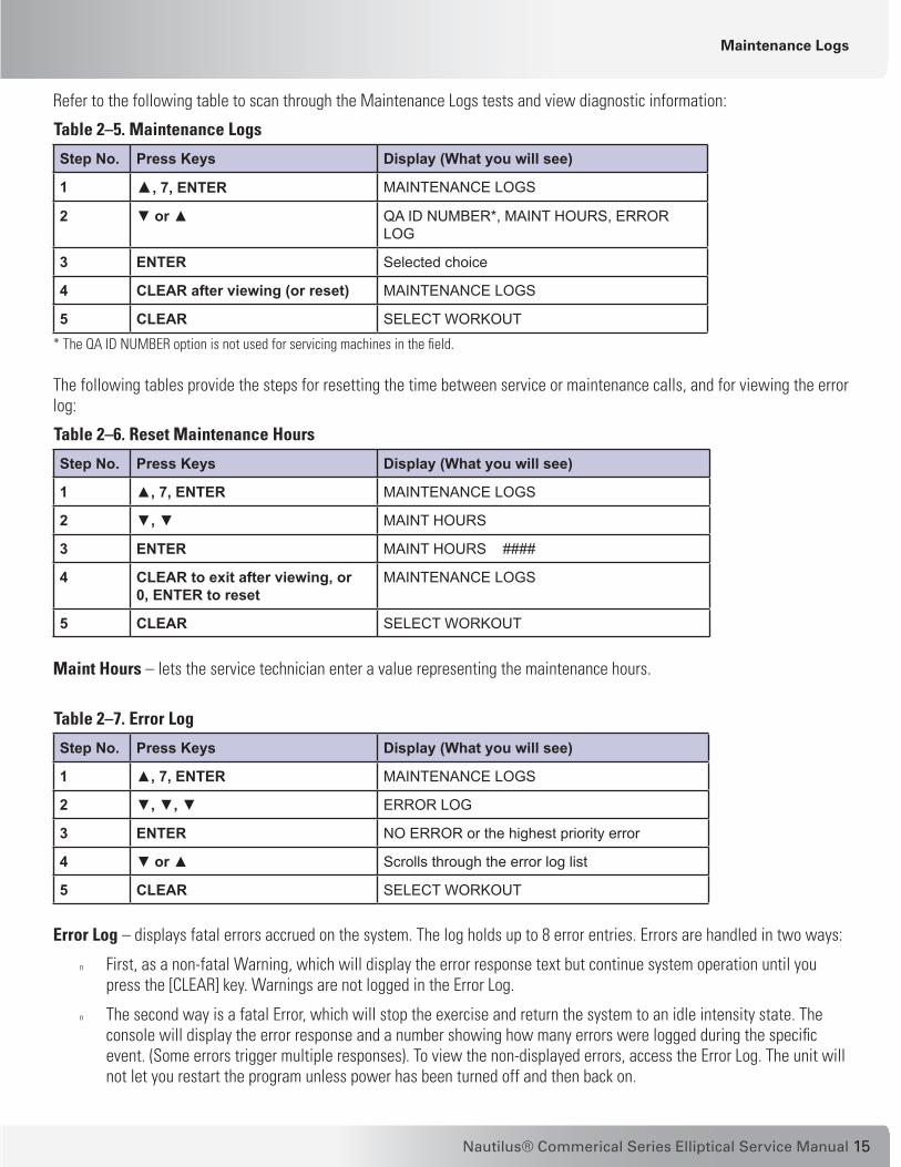
Refer to the following table to scan through the Maintenance Logs tests and view diagnostic information:
Table 2–5. Maintenance Logs
Step No. Press Keys Display (What you will see)
1 ▲, 7, ENTER MAINTENANCE LOGS
2 ▼ or ▲ QA ID NUMBER*, MAINT HOURS, ERROR LOG
3 ENTER Selected choice
4 CLEAR after viewing (or reset) MAINTENANCE LOGS
5 CLEAR SELECT WORKOUT
* The QA ID NUMBER option is not used for servicing machines in the field.
The following tables provide the steps for resetting the time between service or maintenance calls, and for viewing the error log:
Table 2–6. Reset Maintenance Hours
Step No. Press Keys Display (What you will see)
1 ▲, 7, ENTER MAINTENANCE LOGS
2 ▼, ▼ MAINT HOURS
3 ENTER MAINT HOURS ####
4 CLEAR to exit after viewing, or 0, ENTER to reset
MAINTENANCE LOGS
5 CLEAR SELECT WORKOUT
Maint Hours – lets the service technician enter a value representing the maintenance hours.
Table 2–7. Error Log
Step No. Press Keys Display (What you will see)
1 ▲, 7, ENTER MAINTENANCE LOGS
2 ▼, ▼, ▼ ERROR LOG
3 ENTER NO ERROR or the highest priority error
4 ▼ or ▲ Scrolls through the error log list
5 CLEAR SELECT WORKOUT
Error Log – displays fatal errors accrued on the system. The log holds up to 8 error entries. Errors are handled in two ways:
n First, as a non-fatal Warning, which will display the error response text but continue system operation until you press the [CLEAR] key. Warnings are not logged in the Error Log.
n The second way is a fatal Error, which will stop the exercise and return the system to an idle intensity state. The console will display the error response and a number showing how many errors were logged during the specific event. (Some errors trigger multiple responses). To view the non-displayed errors, access the Error Log. The unit will not let you restart the program unless power has been turned off and then back on.
Maintenance Logs

16
Once you access the Error Log, you can cycle the display through 8 entries by using the up/down keys. Each entry displays the error label, its position in the log (1-8), and the time (hours) the error occurred. Note that the most recent error might not be in log position 1—as the number of errors exceeds 8, the newest error will overwrite the oldest. In addition, if a new error is identical to the log’s previous entry, the system checks the time. If the time is the same (within minutes), the error is not logged, to help prevent redundant errors.
The only way to reset the Error Log is to reconfigure the machine.
Machine ConfigurationUse Machine Configuration to change the machine type. The choices are:• Stepper • StepMill • Bike• Elliptical
In general, only the Elliptical machine type is used for the EV916 or E916.
Refer to the following table to scan through and customize the settings:Table 2–8. Machine Configuration
Step No. Press Keys Display (What you will see)
1 ▲, 8, ENTER CHANGE MACHINE
2 ENTER ELLIPTICAL
3 ▼ or ▲ NTM CONFIG RQD, STEPPER CL, STEPMILL, ELLIPTICAL, BIKE
4 ENTER Selects your choice
5 CLEAR SELECT WORKOUT
NTM Config RQD – resets the machine to a “blank” configuration. The configuration must be set to Elliptical (or other machine type) for the workout functions to operate.
Stepper CL – configures the machine as a cordless Stepper. Please note that there is a sense line to let the software know if the system is a Stepper PT (corded); if the system is indeed a Stepper PT, then Stepper PT will appear in the screen instead of Stepper CL.
Machine Status

17Nautilus® Commerical Series Elliptical Service Manual
Wiring Schematics2
Contents
EV916 Top Level Wiring Diagram ........................................................... 18
EV916 Power and Alternator Wiring Diagram ....................................... 19
E916 Console Heart Rate Wiring Diagram ............................................. 20
E916 Main Power Wiring Diagram ........................................................ 21

18
Console Heart Rate Wiring Diagram
EV91
6 El
liptic
al T
op L
evel
Wiri
ng D
iagr
am

19Nautilus® Commerical Series Elliptical Service Manual
Main Power Wiring Diagram
EV91
6 El
liptic
al P
ower
Ele
ctro
nics
and
Alte
rnat
or W
iring
Dia
gram
Not
es:
Plac
e fie
ld d
iode
ass
embl
y (2
1204
) bet
wee
n fie
ld a
nd g
roun
d te
rmin
als
on th
e al
tern
ator
(226
61).

20
E916
Elli
ptic
al C
onso
le H
eart
Rat
e W
iring
Dia
gram
Console Heart Rate Wiring Diagram
4153
1

21Nautilus® Commerical Series Elliptical Service Manual
E916
Elli
ptic
al M
ain
Pow
er W
iring
Dia
gram
Main Power Wiring Diagram
Not
es:
Plac
e fie
ld d
iode
ass
embl
y (2
1204
) bet
wee
n fie
ld a
nd g
roun
d te
rmin
als
on th
e al
tern
ator
(226
61).

22

23Nautilus® Commerical Series Elliptical Service Manual
Assembly Illustrations3
Contents
Service Parts List - EV916 ........................................................................... 25
Cable Connections - EV916 ......................................................................... 31
Assembly Drawings Overview - EV916 ...................................................... 33
Cam Covers (Pods) and Front Knuckle Covers ....................................... 33
Swing Arm / Foot Link Assembly Junction ........................................... 34
Front Mast Assembly / Main Frame Junction ....................................... 34
Drive Train Cover Assembly ................................................................... 35
Drive Train Assembly w/ Main Power Assembly .................................. 35
Crank Cover and Crank Assembly .......................................................... 36
Rear Drive Assembly ............................................................................. 37
Alternator Assembly .............................................................................. 38
Foot Link Assembly (Left) ....................................................................... 38
Foot Link Assembly (Right) .................................................................... 39
Dependency Cover (Cupholder) Assembly ............................................. 39
Swing Arm Assembly ............................................................................ 40
24
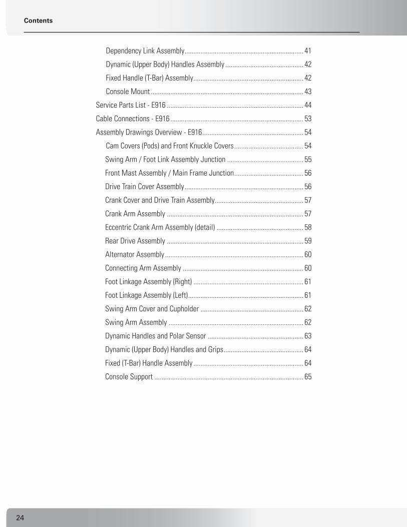
Dependency Link Assembly ................................................................... 41
Dynamic (Upper Body) Handles Assembly ............................................ 42
Fixed Handle (T-Bar) Assembly .............................................................. 42
Console Mount ...................................................................................... 43
Service Parts List - E916 ............................................................................. 44
Cable Connections - E916 ........................................................................... 53
Assembly Drawings Overview - E916 ......................................................... 54
Cam Covers (Pods) and Front Knuckle Covers ....................................... 54
Swing Arm / Foot Link Assembly Junction ........................................... 55
Front Mast Assembly / Main Frame Junction ....................................... 56
Drive Train Cover Assembly ................................................................... 56
Crank Cover and Drive Train Assembly .................................................. 57
Crank Arm Assembly ............................................................................. 57
Eccentric Crank Arm Assembly (detail) ................................................. 58
Rear Drive Assembly ............................................................................. 59
Alternator Assembly .............................................................................. 60
Connecting Arm Assembly .................................................................... 60
Foot Linkage Assembly (Right) .............................................................. 61
Foot Linkage Assembly (Left) ................................................................. 61
Swing Arm Cover and Cupholder .......................................................... 62
Swing Arm Assembly ............................................................................ 62
Dynamic Handles and Polar Sensor ...................................................... 63
Dynamic (Upper Body) Handles and Grips ............................................. 64
Fixed (T-Bar) Handle Assembly .............................................................. 64
Console Support .................................................................................... 65
Contents

25Nautilus® Commerical Series Elliptical Service Manual
Service Parts List - EV916
Assembly Parts List - EV916Part number information in the following table is meant to help you identify the parts in the drawings for ordering replacement parts. Call an authorized Nautilus representative at 1-800-NAUTILUS (624-8458) to order replacement parts and get assistance with your specific replacement or service requirements. Items with no warranty code or part number are replaceable only as part of a higher-level assembly.
WARRANTY NOTES (FOR UNITS IN USA ONLY): 1 - Part covered under standard 3-year parts warranty for replacement. 2 - Part covered under standard 1-year wear item warranty for replacement. 3 - Part covered under standard 15-year frame warranty for replacement.
Table 5-1. Part Identifier List – EV916 Elliptical SRVC# WRNTY-
CODEPART NO./ LEVEL DESCRIPTION1 2 3 4
SM25067 1 25067 ASSY.,BC-1, POWER SUPPLY NA 14029 PINS,CPC NA 21179 CONNECTOR,CPC 11-4 PLUG REVRSE NA 21184 CONNECTOR, BACKSHELL NA 21757 DECAL,WARNING, BATTERY CHARGER NA 25066 POWER SUPPLY, BC-1,1A WALL PACK SM27857 2 27857 COMMERCIAL PRODUCT WARRANTY NA 2 40334 MANUAL, OWNERS, CD, EV916/E916 NA 2 40335 MANUAL, OWNERS, EV916/E916 NA 2 40388 MANUAL, ASSY, E916/EV916
SM12212 1 12212 KEY, .250 SQUARE X .75 LONG SM13584 1 13584 CABLE,ALTERNATOR,3300CE/3900RC SM22242 1 22242 SCREW,.375-16X.75,HEX HD CAPSM22030 1 22030 WASHER, 3/8 USS FLAT SM22046 1 22046 WASHER,FLAT,.562x1.375 x .109 SM22663 1 22663 SCREW,#6 X .50 PHIL,TYPE T SM23081 1 23081 SCREW,.500-13X4.00,HEX HD CAPSM23729 1 23729 WASHER, 3/8 SPLIT LOCKSM40305 1 40305 ASSEMBLY, CRANK ARM, 5300 SM22036 22036 NUT,.250-20,NYLON INSERT SM22047 22047 WASHER,FLAT,1/4 ID X 5/8 OD NA 40303 WELDMENT, CRANK ARM ASSEMBLY SM40562 40562 SCREW,5/16-18 X 1.50 SHC W/NYL SM40697 40697 SCREW,1/4-20 X 3.50,HEX HD CAPSM40767 40767 BRACE,CRANK COVER

26
SRVC# WRNTY-CODE
PART NO./ LEVEL DESCRIPTION1 2 3 4
SM40306 40306 ASSEMBLY, REAR DRIVE, VSL SM12221 1 12221 INTERMEDIATE PULLEY, MOLDED SM12419 1 12419 KEY, .250 SQ X 2.50 LONG SM20205 1 20205 ALTERNATOR, PRESTOLITE, 1992 SM21445 1 21445 ASSY.,SPEED SENSOR,CLIM.SYS,CL SM21448 1 21448 SCREW,.375-16 x 4.50 HEX HD CP SM21774 1 21774 PIN,HITCH SM21778 1 21778 NUT, FLANGE (ALT-FLYWHEEL) SM22029 1 22029 NUT,.375-16,NYLON INSERT SM22030 1 22030 WASHER, 3/8 USS FLAT SM22047 1 22047 WASHER,FLAT,1/4 ID X 5/8 OD SM22070 1 22070 WASHER,.312 SPLIT LOCK SM22093 1 22093 SCREW,.312-18X.75,HEX HD CAP SM22116 1 22116 SCREW,.250-20X2.50,HEX HD CAP SM22191 1 22191 WASHER,SHOULDER,.38 I.D. SM22214 1 22214 WASHER, FLAT, .312 SAE SM22326 1 22326 PIN,CLEVISSM22516 1 22516 CLAMP, CABLE,.75 DIA SM22517 1 22517 DISK, SPEED SENSOR, 4400 CL SM22878 1 22878 SCREW,SET,SOCKET,.250-28 X .38 SM22883 1 22883 SCREW, SET,SOCKET,3/8-16 X .38SM22937 1 22937 SCREW,.375-16 X 3.50,HX HD CAP SM23322 1 23322 BEARING, BALL 17MM X 40MM SM23729 1 23729 WASHER, 3/8 SPLIT LOCK SM24640 1 24640 SCREW,.375-16 X 1.75 HX HD CAP SM25978 1 25978 WHEEL, 3” DIA.SM27654 1 27654 LEVELING PAD (.500-13UNC-2A X 1.88 BASE) SM40301 3 40301 WELDMENT, REAR FRAME, STRIDEMASTER SM40530 1 40530 PULLEY, DRIVE, MACHINED SM40598 3 40598 WELDMENT, ALTERNATOR, TENSIONER SM40605 3 40605 WELDMENT, INTERMED PULLEY TENSIONER SM40608 1 40608 SHAFT, INTERMEDIATE PULLEYSM40609 1 40609 SPACER, INTERMEDIATE SHAFT, LEFT SM40610 1 40610 SPACER, INTERMEDIATE SHAFT, RIGHT SM40611 1 40611 SHAFT, CRANK SM40618 1 40618 BELT, POLY-V,61”,J, 16 RIBSM40619 1 40619 BELT, POLY-V,38”,J, 8 RIB
Service Parts List - EV916
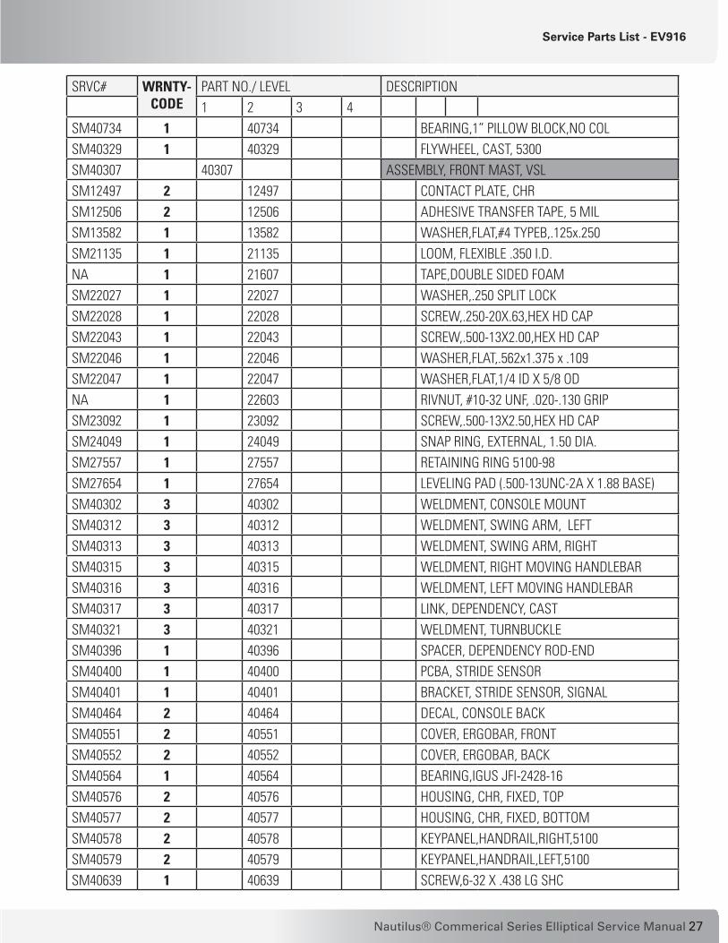
27Nautilus® Commerical Series Elliptical Service Manual
SRVC# WRNTY-CODE
PART NO./ LEVEL DESCRIPTION1 2 3 4
SM40734 1 40734 BEARING,1” PILLOW BLOCK,NO COL SM40329 1 40329 FLYWHEEL, CAST, 5300 SM40307 40307 ASSEMBLY, FRONT MAST, VSL SM12497 2 12497 CONTACT PLATE, CHR SM12506 2 12506 ADHESIVE TRANSFER TAPE, 5 MIL SM13582 1 13582 WASHER,FLAT,#4 TYPEB,.125x.250 SM21135 1 21135 LOOM, FLEXIBLE .350 I.D. NA 1 21607 TAPE,DOUBLE SIDED FOAM SM22027 1 22027 WASHER,.250 SPLIT LOCK SM22028 1 22028 SCREW,.250-20X.63,HEX HD CAP SM22043 1 22043 SCREW,.500-13X2.00,HEX HD CAP SM22046 1 22046 WASHER,FLAT,.562x1.375 x .109 SM22047 1 22047 WASHER,FLAT,1/4 ID X 5/8 OD NA 1 22603 RIVNUT, #10-32 UNF, .020-.130 GRIP SM23092 1 23092 SCREW,.500-13X2.50,HEX HD CAP SM24049 1 24049 SNAP RING, EXTERNAL, 1.50 DIA. SM27557 1 27557 RETAINING RING 5100-98 SM27654 1 27654 LEVELING PAD (.500-13UNC-2A X 1.88 BASE) SM40302 3 40302 WELDMENT, CONSOLE MOUNT SM40312 3 40312 WELDMENT, SWING ARM, LEFT SM40313 3 40313 WELDMENT, SWING ARM, RIGHT SM40315 3 40315 WELDMENT, RIGHT MOVING HANDLEBARSM40316 3 40316 WELDMENT, LEFT MOVING HANDLEBARSM40317 3 40317 LINK, DEPENDENCY, CAST SM40321 3 40321 WELDMENT, TURNBUCKLE SM40396 1 40396 SPACER, DEPENDENCY ROD-END SM40400 1 40400 PCBA, STRIDE SENSOR SM40401 1 40401 BRACKET, STRIDE SENSOR, SIGNALSM40464 2 40464 DECAL, CONSOLE BACKSM40551 2 40551 COVER, ERGOBAR, FRONT SM40552 2 40552 COVER, ERGOBAR, BACK SM40564 1 40564 BEARING,IGUS JFI-2428-16 SM40576 2 40576 HOUSING, CHR, FIXED, TOP SM40577 2 40577 HOUSING, CHR, FIXED, BOTTOM SM40578 2 40578 KEYPANEL,HANDRAIL,RIGHT,5100 SM40579 2 40579 KEYPANEL,HANDRAIL,LEFT,5100 SM40639 1 40639 SCREW,6-32 X .438 LG SHC
Service Parts List - EV916

28
SRVC# WRNTY-CODE
PART NO./ LEVEL DESCRIPTION1 2 3 4
SM40642 2 40642 CONTACT PLATE, CHR, LONG SM40643 2 40643 HOUSING, CHR, DYNAMIC, FRONT SM40644 2 40644 HOUSING, CHR, DYNAMIC, REAR SM40651 1 40651 WASHER,NYLATRON,1.505 X 2.250 SM40652 1 40652 WASHER,WAVE,1.560 X 1.8750 X .SM40654 1 40654 SCREW,10-32X.75,PANHD W/LK WASHER SM40655 1 40655 NUT,LOCK,CONICAL TOP,1/2-13 SM40679 1 40679 CABLE,ASSY,T-BAR GRIP TO CONSOLE SM40680 1 40680 ASSY,CABLE,ELLIPTICAL SWINGARM SM40692 1 40692 PCB ASSEMBLY,ELLIPT SWINGARM SM40696 1 40696 CABLE,C41 SWINGARM INTERMEDIATESM40760 1 40760 LABEL,SWING ARM,WIRE,RH SM40761 1 40761 LABEL,SWING ARM,WIRE,LH SM40776 2 40776 ADHESIVE,TRANSFER TAPE,25 MIL SM40777 1 40777 SCREW,6-32X1.25 LG HEX SHC SM41269 1 41269 GROMMET, 2870, 7/8” IDSM40318 40318 ASSEMBLY, FOOT LINK, RIGHT SM22027 1 22027 WASHER,.250 SPLIT LOCKSM22028 1 22028 SCREW,.250-20X.63,HEX HD CAP SM22032 1 22032 NUT,5/16-18 NC NYLON INSRT HEX SM22047 1 22047 WASHER,FLAT,1/4 ID X 5/8 OD NA 3 40309 WELDMENT, MAIN FOOTLINK RIGHT SM40424 2 40424 HOUSING, FOOT PAD, RIGHT SM40434 2 40434 FOOT PAD, RIGHT SM40443 1 40443 SCREW, 10-32 X 1.00 LG, OVAL HD PH, SSSM40450 1 40450 RUBBER, BRAKE SM40457 1 40457 DIA. 3/8 X 1/2 LG SHOULDER; 5/16 - 18 UNC X
1/2 LG THREADS; SOCKET HEAD SM40460 1 40460 BRKT, BRAKE RUBBER MNTG, LEFT, OUTSIDE SM40461 1 40461 BRKT, BRAKE RUBBER MNTG, LEFT, INSIDE SM40319 40319 ASSEMBLY, FOOT LINK, LEFT SM22032 1 22032 NUT,5/16-18 NC NYLON INSRT HEX SM22027 1 22027 WASHER,.250 SPLIT LOCK SM22028 1 22028 SCREW,.250-20X.63,HEX HD CAP SM22047 1 22047 WASHER,FLAT,1/4 ID X 5/8 OD SM22120 1 22120 WASHER, #6 INTERNAL TOOTH LOCK NA 2 40310 WELDMENT, MAIN FOOTLINK LEFT
Service Parts List - EV916

29Nautilus® Commerical Series Elliptical Service Manual
SRVC# WRNTY-CODE
PART NO./ LEVEL DESCRIPTION1 2 3 4
SM40425 2 40425 HOUSING, FOOR PAD, LEFTSM40435 2 40435 FOOT PAD, LEFT SM40443 1 40443 SCREW, 10-32 X 1.00 LG, OVAL HD PH, SS SM40447 1 40447 SPRING, RETURN SM40449 1 40449 MOTOR, BRAKE SM40450 1 40450 RUBBER, BRAKE SM40451 1 40451 BRKT, BRAKE RUBBER MNTG,LEFT, OUTSIDE SM40452 1 40452 BRKT, BRAKE RUBBER MNTG,LEFT, INSIDE SM40453 1 40453 CAM, BRAKE NA 1 40454 GUIDE, BRAKE CAM SM40455 1 40455 SCREW, SET, #10-32 X .1875, SM40456 1 40456 SCREW, #6-32 X .25, THR FORM, PAN HD PH SM40457 1 40457 DIA. 3/8 X 1/2 LG SHLDR; 5/16 - 18 UNC X 1/2
LG THREADS; SOCKET HEAD SM40458 1 40458 SCREW, #5-40 X .25, THR FORM, PAN HD PH SM41269 1 41269 GROMMET, 2870, 7/8” IDSM40358 1 40358 SHAFT, SWING ARM, BOTTOM, 5300 SM40364 1 40364 ROLLER, CAM SM40381 1 40381 COVER, CRANK, STEEL SM40416 2 40416 COVER, RIGHT REAR, FRONT SM40417 2 40417 COVER, RIGHT REAR, BACK SM40418 2 40418 COVER, LEFT REAR, FRONT SM40419 2 40419 COVER, LEFT REAR, BACK SM40420 2 40420 COVER, CAM, OUTSIDE, RIGHT SM40421 2 40421 COVER, CAM, OUTSIDE, LEFT SM40422 2 40422 COVER, CAM, INSIDE, RIGHT SM40423 2 40423 COVER, CAM, INSIDE, LEFT SM40426 2 40426 COVER, KNUCKLE, #1 SM40427 2 40427 COVER, KNUCKLE, #2 SM40428 2 40428 COVER, DEPENDENCY, UPPER, FRONT SM40430 2 40430 COVER, DEPENDENCY LEFT, FRONT SM40431 2 40431 COVER, DEPENDENCY, RIGHT, FRONT SM40436 2 40436 DECAL,ID,RIGHT,5300 SM40437 2 40437 DECAL,ID,LEFT,5300 SM40438 2 40438 BRACKET, FRONT PLASTIC, SUPPORT SM40439 2 40439 COVER, UPPER SWING ARM, #1 SM40440 2 40440 COVER, UPPER SWING ARM, #2
Service Parts List - EV916

30
SRVC# WRNTY-CODE
PART NO./ LEVEL DESCRIPTION1 2 3 4
SM40441 2 40441 COVER, UPPER SWING ARM, RIGHT SM40442 2 40442 COVER, UPPER SWING ARM, LEFT SM40462 1 40462 ASSY, CABLE, BRAKE MOUNT SM40527 2 40527 COVER,DRIVTRAIN,TOPSM40556 2 40556 COVER, FRONT, BOTTOM, LEFT SM40558 2 40558 COVER, FRONT, BOTTOM, RIGHT SM40601 40601 ASSEMBLY, LOWER CONTROL BOARD SM13572 1 13572 ASSY,PCB,POWER CONTROL BOARD SM14123 1 14123 BATTERY,6V SM22109 1 22109 WASHER, #8 INTERNAL TOOTH LOCK SM22133 1 22133 SCREW,#8-32 X .75,PHIL PAN HD SM22938 1 22938 FASTENER,HOOK SM22939 1 22939 FASTENER,LOOP SM24279 1 24279 TYRAP,.14x11.0 SM25206 1 25206 SIL PAD SM40635 1 40635 ASSY,LOWER CONTROL BOARD BRACKET SM40603 40603 ASSEMBLY, RESISTOR AND BRACKET, STRIDEMASTER SM22022 1 22022 NUT, 1/4-20 NC FINISH HEX SM22027 1 22027 WASHER,.250 SPLIT LOCK SM22047 1 22047 WASHER,FLAT,1/4 ID X 5/8 OD SM25611 1 25611 ASSEMBLY, RESISTOR, 3800 SM13580 1 13580 WASHER,#8 SAE FLAT SM22109 1 22109 WASHER, #8 INTERNAL TOOTH LOCK SM22110 1 22110 NUT,#8-32,HEX MACH SM22134 1 22134 SCREW,#8-32 X .38,PHIL PAN HD SM23783 1 23783 ASSY,CABLE,RESISTOR SM24989 1 24989 RESISTOR,0.5 OHM, 240 WATT SM40604 1 40604 RACKET,RESISTOR,HEAT SHIELD SM40632 1 40632 SCREW,.250-20UNC X .75LG SHC SM40616 1 40616 SPACER, CRANK SHAFTSM40651 1 40651 WASHER,NYLATRON,1.505 X 2.250 SM40654 1 40654 SCREW,10-32X.75,PANHD W/LK WASHER SM40655 1 40655 NUT,LOCK,CONICAL TOP,1/2-13 SM40667 1 40667 SCREW, 5/16-18X.75,BH CAP,SS SM40668 1 40668 WASHER,FLAT,11/32IDX3/4ODX.050 SM40669 1 40669 WASHER,SPRING LOCK,5/16,SS SM40670 1 40670 SCREW,1/4-20X.75,PAN HD,W/LOCK
Service Parts List - EV916

31Nautilus® Commerical Series Elliptical Service Manual
SRVC# WRNTY-CODE
PART NO./ LEVEL DESCRIPTION1 2 3 4
SM40671 1 40671 SCREW,10-32X.50,PAN HEAD,SS,BL SM40676 1 40676 CABLE ASSY,INLINE TO PWR PCBASM40677 1 40677 ASSY,MAIN POWER,ELLIPTICAL SM40678 1 40678 CABLE,ASSY,BATTERY,ELLIPTICAL SM40679 1 40679 CABLE,ASSY,T-BAR GRIP TO CONSOLE SM40680 1 40680 ASSY,CABLE,ELLIPTICAL SWINGARM SM40681 1 40681 ASSY, CABLE, C41 CHR BREAKOUTSM40710 1 40710 CABLE ASSY,CONSOLE TO INLINE SM40801 1 40801 ASSY, CONSOLE, C51, LCD
Cable Connections - EV916
Cable Connections - EV916Two of the main cable connections for the EV916 elliptical are shown below. Wiring diagrams for the EV916 console, handles and main power are provided in Section 2.
Front Mast to Main Frame Connection:
CONNECT CABLE (PN 40471) FROM FRONT MAST TO CABLE (PN 40844) FROM MAIN FRAME CENTER TUBE BEFORE SECURING FLANGES TOGETHER. THE COLOR-CODED CABLES SNAP TOGETHER WITH THE M/F CONNECTORS FOR THE CORRESPSONDING CABLE COLORS.
NOTE: TAKE CARE NOT TO PINCH CABLES WHEN ASSEMBLING.
CABLES

32
Left Swing Arm to Foot Link Connection:
Cable Connections - EV916
CONNECT THE FOOTLINK AND SWING ARM CABLE (PN 40470) USING M/F CONNECTORS FOR CORRESPONDING COLORS. (SEE FIGURE 1.)
CAREFULLY INSERT THE CONNECTORS AND ZIP-TIED LOOP INTO THE SWING ARM (PN 40312) TUBE OPENING. (SEE FIGURE 2.)
NOTE: If connectors are not inserted into the Swing Arm tube, they will be damaged during use!
Figure 1
Figure 2
REINSTALL THE SWING ARM RUBBER GROMMET (PN 41269), AND INSERT ANY REMAINING SLACK CABLE (PN 40470) INTO EITHER TUBE. MAKE SURE THE SWING ARM GROMMET (PN 41269) IS FULLY INSTALLED AND THAT ONLY THE SHEATHED CABLE (PN 40470) IS EXPOSED. (SEE FIGURE 3.)
Figure 3
Footlink Cable
Swing Arm Cable
3/4 inch Loop
LengthSwing Arm Connector
Footlink Connector Swing Arm
Grommet

33Nautilus® Commerical Series Elliptical Service Manual
Assembly Drawings - EV916
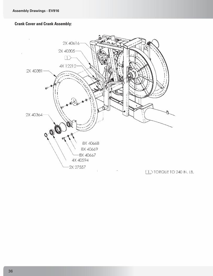
Assembly Drawings Overview - EV916Some drawings include specific notes, represented by . Refer to these notes when replacing parts because they mention critical torque specs and other important servicing information.
Refer to the Parts List in the preceding pages to locate information on the part numbers that are called out in the assembly drawings.
1.
Cam Covers (Pods) and Front Knuckle Covers:

34
Swing Arm / Foot Link Assembly Junction:
Front Mast Assembly / Main Frame Junction:
Assembly Drawings - EV916

35Nautilus® Commerical Series Elliptical Service Manual
Drive Train Cover Assembly:
Drive Train Assembly w/ Main Power Assembly:
Assembly Drawings - EV916
36
Crank Cover and Crank Assembly:
Assembly Drawings - EV916

37Nautilus® Commerical Series Elliptical Service Manual
Rear Drive Assembly:
Assembly Drawings - EV916
2288322883

38
Alternator Assembly:
Assembly Drawings - EV916
Foot Link Assembly (Left):
.020-.040 AIR GAP BETWEEN SENSOR (PN 21445) AND DISK (PN 22517).
.

39Nautilus® Commerical Series Elliptical Service Manual
Assembly Drawings - EV916
Dependency Cover (Cupholder) Assembly:
Foot Link Assembly (Right):

40
Assembly Drawings - EV916
Swing Arm Assembly:
.

41Nautilus® Commerical Series Elliptical Service Manual
Assembly Drawings - EV916
Dependency Link Assembly:
NOTES:

42
Assembly Drawings - EV916
Dynamic (Upper Body) Handle Assembly:
Fixed (T-Bar) Handle Assembly:
(ASSEMBLY SHOWN FROM RIGHT SIDE OF FRONT MAST, LOOKING TOWARD REAR DRIVE.)
.

43Nautilus® Commerical Series Elliptical Service Manual
Assembly Drawings - EV916
Console Mount:
POSITION CONSOLE SO THAT CABLES CAN BE CONNECTED USING THE PROPER CONNECTORS.

44
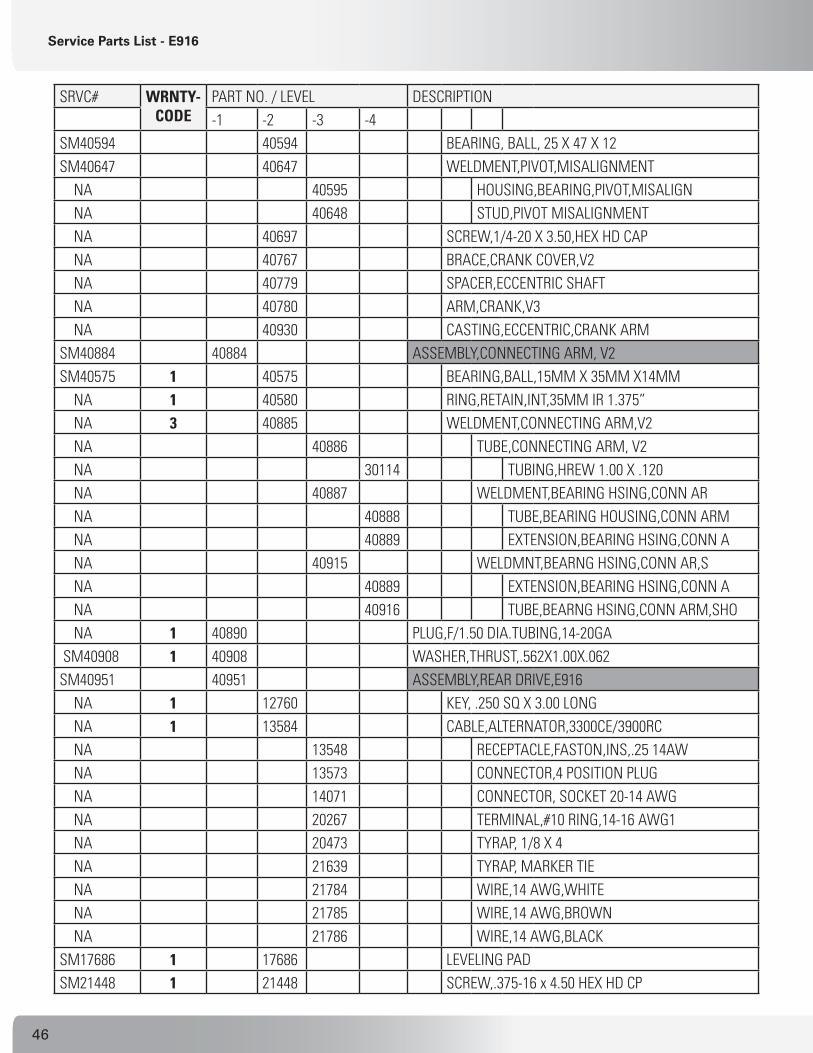
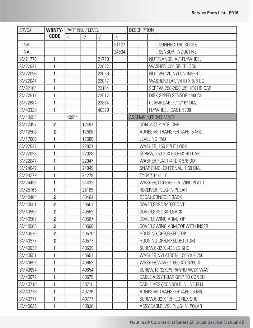
Service Parts List - E916Part number information in the following table is meant to help you identify the parts in the drawings for ordering replacement parts. Call an authorized Nautilus® representative at 1-800-NAUTILUS (624-8458) to order replacement parts and get assistance with your specific replacement or service requirements. Items with no warranty code or part number are replaceable only as part of a higher-level assembly only.
WARRANTY NOTES (FOR UNITS IN USA ONLY): 1 - Part covered under standard 3-year parts warranty for replacement. 2 - Part covered under standard 1-year wear item warranty for replacement. 3 - Part covered under standard 15-year frame warranty for replacement.
Table 5-2. Part Identifier List – E916 Elliptical
SRVC# WRNTY-CODE
PART NO. / LEVEL DESCRIPTION-1 -2 -3 -4
SM25067 2 25067 ASSY.,BC-1, POWER SUPPLY NA 14029 PINS,CPC NA 21179 CONNECTOR,CPC 11-4 PLUG REVRSE NA 21184 CONNECTOR, BACKSHELL NA 21757 DECAL,WARNING,BATTERY CHARGER NA 25066 POWER SUPPLY,BC-1,1A WALL PACK SM27857 2 27857 COMMERCIAL PRODUCT WARRANTY NA 2 40334 MANUAL, OWNERS, CD, EV916/E916 NA 2 40335 MANUAL, OWNERS, EV916/E916 NA 2 40388 MANUAL, ASSY, E916/EV916
SM12212 2 12212 KEY,.250 SQUARE X .750 LONG SM12419 2 12419 KEY, .250 SQ X 2.50 LONG SM22030 2 22030 WASHER, 3/8 USS FLAT SM22042 2 22042 NUT,.500-13,NYLON INSERT SM22046 2 22046 WASHER,FLAT,.562x1.375 x .109 SM22242 2 22242 SCREW,.375-16X.75,HEX HD CAP SM23729 2 23729 WASHER, 3/8 SPLIT LOCK SM26669 2 26669 SCREW,.500-13x4.50,HEX HD CAPSM29062 2 29062 SCREW,1/4-28X 5/8 SOCKET HD CP SM40358 2 40358 SHAFT, SWING ARM PIVOTSM40381 1 40381 COVER, CRANK, STEEL SM40426 2 40426 COVER, KNUCKLE, FRONT LEFT SM40427 2 40427 COVER, KNUCKLE, FRONT RIGHT SM40436 2 40436 DECAL,ID,RIGHT SM40437 2 40437 DECAL,ID,LEFT
Service Parts List - E916

45Nautilus® Commerical Series Elliptical Service Manual
SRVC# WRNTY-CODE
PART NO. / LEVEL DESCRIPTION-1 -2 -3 -4
SM40525 2 40525 COVER,DRIVETRAIN,RIGHT SM40526 2 40526 COVER,DRIVETRAIN,LEFTSM40527 2 40527 COVER,DRIVTRAIN,TOPSM40556 2 40556 COVER,FRONT,BOTTOM,LEFT SM40558 2 40558 COVER,FRONT,BOTTOM,RIGHT SM40592 2 40592 COVER,POD,TOP,LEFTSM40593 2 40593 COVER,POD,BOTTOM,LEFT SM40596 2 40596 COVER,POD,TOP,RIGHT SM40597 2 40597 COVER,POD,BOTTOM,RIGHT SM40616 1 40616 SPACER,CRANK SHAFT SM40654 1 40654 SCREW,10-32X.75,PANHD W/LK WAS SM40667 1 40667 SCREW, 5/16-18X.75,BH CAP,SS SM40668 1 40668 WASHER,FLAT,11/32IDX3/4ODX.050 SM40669 1 40669 WASHER,SPRING LOCK,5/16,SS SM40670 1 40670 SCREW,1/4-20X.75,PAN HD,W/LOCK SM40751 1 40751 RING,RETAINING,EXTERNAL,15MM SM40783 1 40783 ASSEMBLY,CRANK ARM,RIGHT,V2 SM12212 12212 KEY,.250 SQUARE X .750 LONG SM22036 22036 NUT,.250-20,NYLON INSERT SM22047 22047 WASHER,FLAT,1/4 ID X 5/8 ODSM27557 27557 RETAINING RING 5100-98 SM40562 40562 SCREW,5/16-18 X 1.50 SHC W/NYL SM40594 40594 BEARING, BALL, 25 X 47 X 12 SM40647 40647 WELDMENT,PIVOT,MISALIGNMENT NA 40595 HOUSING,BEARING,PIVOT,MISALIGN NA 40648 STUD,PIVOT MISALIGNMENT NA 40697 SCREW,1/4-20 X 3.50,HEX HD CAP NA 40767 BRACE,CRANK COVER,V2 NA 40779 SPACER,ECCENTRIC SHAFT NA 40780 ARM,CRANK,V3 NA 40930 CASTING,ECCENTRIC,CRANK ARM SM40784 1 40784 ASSEMBLY,CRANK ARM,LEFT,V2 SM12212 12212 KEY,.250 SQUARE X .750 LONG SM22036 22036 NUT,.250-20,NYLON INSERT SM22047 22047 WASHER,FLAT,1/4 ID X 5/8 ODSM27557 27557 RETAINING RING 5100-98 SM40562 40562 SCREW,5/16-18 X 1.50 SHC W/NYL
Service Parts List - E916
46
SRVC# WRNTY-CODE
PART NO. / LEVEL DESCRIPTION-1 -2 -3 -4
SM40594 40594 BEARING, BALL, 25 X 47 X 12 SM40647 40647 WELDMENT,PIVOT,MISALIGNMENT NA 40595 HOUSING,BEARING,PIVOT,MISALIGN NA 40648 STUD,PIVOT MISALIGNMENT NA 40697 SCREW,1/4-20 X 3.50,HEX HD CAP NA 40767 BRACE,CRANK COVER,V2 NA 40779 SPACER,ECCENTRIC SHAFT NA 40780 ARM,CRANK,V3 NA 40930 CASTING,ECCENTRIC,CRANK ARMSM40884 40884 ASSEMBLY,CONNECTING ARM, V2SM40575 1 40575 BEARING,BALL,15MM X 35MM X14MM NA 1 40580 RING,RETAIN,INT,35MM IR 1.375” NA 3 40885 WELDMENT,CONNECTING ARM,V2 NA 40886 TUBE,CONNECTING ARM, V2 NA 30114 TUBING,HREW 1.00 X .120 NA 40887 WELDMENT,BEARING HSING,CONN AR NA 40888 TUBE,BEARING HOUSING,CONN ARM NA 40889 EXTENSION,BEARING HSING,CONN A NA 40915 WELDMNT,BEARNG HSING,CONN AR,S NA 40889 EXTENSION,BEARING HSING,CONN A NA 40916 TUBE,BEARNG HSING,CONN ARM,SHO NA 1 40890 PLUG,F/1.50 DIA.TUBING,14-20GA SM40908 1 40908 WASHER,THRUST,.562X1.00X.062 SM40951 40951 ASSEMBLY,REAR DRIVE,E916 NA 1 12760 KEY, .250 SQ X 3.00 LONG NA 1 13584 CABLE,ALTERNATOR,3300CE/3900RC NA 13548 RECEPTACLE,FASTON,INS,.25 14AW NA 13573 CONNECTOR,4 POSITION PLUG NA 14071 CONNECTOR, SOCKET 20-14 AWG NA 20267 TERMINAL,#10 RING,14-16 AWG1 NA 20473 TYRAP, 1/8 X 4 NA 21639 TYRAP, MARKER TIE NA 21784 WIRE,14 AWG,WHITE NA 21785 WIRE,14 AWG,BROWN NA 21786 WIRE,14 AWG,BLACK SM17686 1 17686 LEVELING PADSM21448 1 21448 SCREW,.375-16 x 4.50 HEX HD CP
Service Parts List - E916

47Nautilus® Commerical Series Elliptical Service Manual
SRVC# WRNTY-CODE
PART NO. / LEVEL DESCRIPTION-1 -2 -3 -4
SM21774 1 21774 PIN,HITCH SM22029 1 22029 NUT,.375-16,NYLON INSERT SM22030 1 22030 WASHER, 3/8 USS FLAT SM22047 1 22047 WASHER,FLAT,1/4 ID X 5/8 ODSM22070 1 22070 WASHER,.312 SPLIT LOCKSM22093 1 22093 SCREW,.312-18X.75,HEX HD CAP SM22116 1 22116 SCREW,.250-20X2.50,HEX HD CAP SM22191 1 22191 WASHER,SHOULDER,.38 I.D.SM22214 1 22214 WASHER, FLAT, .312 SAE SM22326 1 22326 PIN,CLEVIS SM22663 1 22663 SCREW,#6 X .50 PHIL,TYPE T SM22878 1 22878 SCREW,SET,SOCKET,.250-28 X .38 SM22883 1 22883 SCREW, SET,SOCKET,3/8-16 X .38 SM22937 1 22937 SCREW,.375-16 X 3.50,HX HD CAPSM23729 1 23729 WASHER, 3/8 SPLIT LOCK SM24640 1 24640 SCREW,.375-16 X 1.75 HX HD CAPSM25978 1 25978 WHEEL, 3” DIA SM40501 3 40501 WELDMENT,REAR FRAME,STRIDEMAST SM40530 1 40530 PULLEY,DRIVE,MACHINED SM40528-05 40528 HUB,PULLEY,DRIVE SM40598 3 40598 WELDMENT, ALTERNATOR TENSIONER NA 40599 TAB,ALTERNATOR,TENSIONER NA 40600 SHAFT,THREADED,ALTERNATOR,TENS SM40601 40601 ASSEMBLY,LOWER CONTROL BOARD SM13572 1 13572 ASSY,PCB,POWER CONTROL BOARDSM14123 1 14123 BATTERY,6VSM22109 1 22109 WASHER, #8 INTERNAL TOOTH LOCK SM22133 1 22133 SCREW,#8-32 X .75,PHIL PAN HD SM22938 1 22938 FASTENER,HOOK SM22939 1 22939 FASTENER,LOOP SM24279 1 24279 TYRAP,.14x11.0 SM25206 1 25206 SIL PAD SM40635 1 40635 ASSY,LOWER CONTROL BOARD BRACKSM40603 40603 ASSY,RESISTOR & BRACKET,STRIDE NA 1 22022 NUT, 1/4-20 NC FINISH HEX NA 1 22027 WASHER,.250 SPLIT LOCK NA 1 22047 WASHER,FLAT,1/4 ID X 5/8 OD
Service Parts List - E916

48
SRVC# WRNTY-CODE
PART NO. / LEVEL DESCRIPTION-1 -2 -3 -4
NA 1 25611 ASSEMBLY, RESISTOR, 3800 SM13580 1 13580 WASHER,#8 SAE FLAT SM22109 1 22109 WASHER, #8 INTERNAL TOOTH LOCK SM22110 1 22110 NUT,#8-32,HEX MACH SM22134 1 22134 SCREW,#8-32 X .38,PHIL PAN HDSM23783 1 23783 ASSY,CABLE,RESISTOR SM24989 1 24989 RESISTOR,0.5 OHM, 240 WATT SM40604 1 40604 BRACKET,RESISTOR,HEAT SHIELD SM40632 1 40632 SCREW,.250-20UNC X .75LG SHC SM40605 3 40605 WELDMENT, INT PULLEY TENSIONERSM40607 40607 HUB,INTERMEDIATE PULLEY SHAFT SM40631 40631 ASSY,INTERMED PULLEY BRACKET NA 25218 NUT,SELF CLINCHING,.250-20 NA 25325 PEM NUT, 3/8-16 NA 40606 BRACKET,INTERMED PULLEY TENSIO SM40608 1 40608 SHAFT,INTERMEDIATE PULLEY SM40609 1 40609 SPACER,INTERMEDIATE SHAFT,LEFTSM40610 1 40610 SPACER,INTERMEDIATE SHAFT,RIGH SM40611 1 40611 SHAFT,CRANKSM40654 1 40654 SCREW,10-32X.75,PANHD W/LK WAS SM40678 1 40678 CABLE,ASSY,BATTERY,ELLIPTICAL SM40734 1 40734 BEARING,1” PILLOW BLOCK,NO COL SM40844 1 40844 CABLE ASSY,MAIN LOWER,EV916 SM40909 1 40909 BELT,POLY-V,61”,J,10 RIBS SM40910 1 40910 BELT,POLY-V,38”,J,6 RIB SM40952 40952 ASSEMBLY,INTERMEDIATE PULLEY NA 1 12221 INTERMEDIATE PULLEY, MOLDED NA 12347 HUB, INTERMEDIATE PULLY SM23322 1 23322 BEARING, BALL 17MM X 40MM SM40953 40953 ASSEMBLY,ALTERNATOR SM20205 1 20205 ALTERNATOR,PRESTOLITE,1992 SM21204 1 21204 ASSY,FIELD,DIODE NA 20456 CONNECTOR, LUG 18-22 AWG NA 20751 TERMINAL,#10 RING,16-22 AWG NA 22261 DIODE, IN5404 SM21445 1 21445 ASSY.,SPEED SENSOR,CLIM.SYS,CL NA 21126 CONNECTOR,2-POS SOCKET HOUSING
Service Parts List - E916
49Nautilus® Commerical Series Elliptical Service Manual
SRVC# WRNTY-CODE
PART NO. / LEVEL DESCRIPTION-1 -2 -3 -4
NA 21127 CONNECTOR, SOCKET NA 24594 SENSOR, INDUCTIVE SM21778 1 21778 NUT,FLANGE (ALT-FLYWHEEL) SM22027 1 22027 WASHER,.250 SPLIT LOCK SM22036 1 22036 NUT,.250-20,NYLON INSERT SM22047 1 22047 WASHER,FLAT,1/4 ID X 5/8 OD SM22164 1 22164 SCREW,.250-20X1.25,HEX HD CAP SM22517 1 22517 DISK,SPEED,SENSOR,4400CL SM22884 1 22884 CLAMP,CABLE,11/16” DIA. SM40329 1 40329 FLYWHEEL, CAST, 5300 SM40954 40954 ASSEMBLY,FRONT MAST SM12497 2 12497 CONTACT PLATE, CHR SM12506 2 12506 ADHESIVE TRANSFER TAPE, 5 MIL SM17686 1 17686 LEVELING PAD SM22027 1 22027 WASHER,.250 SPLIT LOCK SM22028 1 22028 SCREW,.250-20X.63,HEX HD CAPSM22047 1 22047 WASHER,FLAT,1/4 ID X 5/8 OD SM24049 1 24049 SNAP RING, EXTERNAL, 1.50 DIA. SM24279 1 24279 TYRAP,.14x11.0 SM24432 1 24432 WASHER,#10 SAE FLAT,ZINC PLATDSM25165 1 25165 RECEIVER,PLUG-IN,POLAR SM40464 2 40464 DECAL,CONSOLE BACK SM40551 2 40551 COVER,ERGOBAR,FRONT SM40552 2 40552 COVER,ERGOBAR,BACK SM40567 2 40567 COVER,SWING ARM,TOP SM40568 2 40568 COVER,SWING ARM,TOP,WITH INSER SM40576 2 40576 HOUSING,CHR,FIXED,TOP SM40577 2 40577 HOUSING,CHR,FIXED,BOTTOMSM40639 1 40639 SCREW,6-32 X .438 LG SHC SM40651 1 40651 WASHER,NYLATRON,1.505 X 2.250 SM40652 1 40652 WASHER,WAVE,1.560 X 1.8750 X SM40654 1 40654 SCREW,10-32X.75,PANHD W/LK WAS SM40679 1 40679 CABLE,ASSY,T-BAR GRIP TO CONSO SM40710 1 40710 CABLE ASSY,CONSOLE-INLINE,ELLI SM40776 1 40776 ADHESIVE,TRANSFER TAPE,25 MIL SM40777 1 40777 SCREW,6-32 X 1.5” LG HEX SHC SM40836 1 40836 ASSY,CABLE, VSL PLUG-IN, POLAR
Service Parts List - E916

50
SRVC# WRNTY-CODE
PART NO. / LEVEL DESCRIPTION-1 -2 -3 -4
SM40880 2 40880 COVER, CUP HOLDER, TOP, V2 SM40881 2 40881 COVER, CUP HOLDER, BOTTOM, V2 SM40892 3 40892 WELDMENT, CONSOLE MOUNT, V2 SM40955 40955 ASSEMBLY,SWING ARM SM40564 1 40564 BEARING,IGUS JFI-2428-16 SM40893 3 40893 WELDMENT,SWING ARM,E916,V2 SM40380 40380 HOUSING,BEARING,SWING ARM NA 40409 PLATE, MOUNTING, UPPER HANDLE SM40410 40410 HOUSING,BEARING,SWING ARM,LOWE NA 40561 TUBE,SWING ARM SM40956 40956 ASSY,UPPER BODY,ARM,RIGHT,E916 SM21135 1 21135 LOOM, FLEXIBLE .350 I.D. NA 2 21607 TAPE,DOUBLE SIDED FOAM NA 2 40466 KEYPANEL,HANDRAIL,RIGHT,EV9.16 NA 1 40639 SCREW,6-32 X .438 LG SHC NA 2 40642 CONTACT PLATE,CHR,LONG NA 2 40643 HOUSING,CHR,DYNAMIC,FRONT NA 2 40644 HOUSING,CHR,DYNAMIC,REAR NA 1 40680 ASSY,CABLE,ELLIPTICAL SWINGARM SM40692 1 40692 PCB ASSEMBLY,ELLIPT SWINGARM SM40761 2 40761 LABEL,SWING ARM,WIRE,LH SM40776 2 40776 ADHESIVE,TRANSFER TAPE,25 MILSM40896 3 40896 WELDMENT, UPPER BODY, RIGHT,V2 NA 40571 PLATE,UPPER BODY HANDLE,TOP NA 40653 TUBE, CHR, UPPER BODY HANDLE NA 40906 TUBE, UPPER BODY, RIGHT,V2 SM40957 40957 ASSY,UPPER BODY,ARM,LEFT,E916 SM21135 1 21135 LOOM, FLEXIBLE .350 I.D. NA 2 21607 TAPE,DOUBLE SIDED FOAM SM40465 2 40465 KEYPANEL,HANDRAIL,LEFT,EV9.16 SM40639 1 40639 SCREW,6-32 X .438 LG SHC SM40642 2 40642 CONTACT PLATE,CHR,LONG SM40643 2 40643 HOUSING,CHR,DYNAMIC,FRONT SM40644 2 40644 HOUSING,CHR,DYNAMIC,REAR SM40680 1 40680 ASSY,CABLE,ELLIPTICAL SWINGARM SM40692 1 40692 PCB ASSEMBLY,ELLIPT SWINGARM SM40760 2 40760 LABEL,SWING ARM,WIRE,RH
Service Parts List - E916

51Nautilus® Commerical Series Elliptical Service Manual
SRVC# WRNTY-CODE
PART NO. / LEVEL DESCRIPTION-1 -2 -3 -4
SM40776 2 40776 ADHESIVE,TRANSFER TAPE,25 MIL SM40895 3 40895 WELDMENT,UPPER BODY, LEFT, V2 NA 40571 PLATE,UPPER BODY HANDLE,TOP NA 40653 TUBE, CHR, UPPER BODY HANDLE NA 40905 TUBE, UPPER BODY, LEFT, V2 SM40958 40958 ASSEMBLY,FOOT LINK, RIGHT SM40424 2 40424 HOUSING,FOOT PAD,RIGHT SM40434 2 40434 FOOT PAD,RIGHT SM40443 1 40443 SCREW,10-32 X 1.0, OVAL HD,PHL SM40646 1 40646 SHAFT,FOOT PIVOT SM40667 1 40667 SCREW, 5/16-18X.75,BH CAP,SS SM40668 1 40668 WASHER,FLAT,11/32IDX3/4ODX.050 SM40669 1 40669 WASHER,SPRING LOCK,5/16,SS SM40877 3 40877 WELDMENT,FOOT SUPPORT,RIGHT,V5 NA 40798 BRKT,MTING,CONN ARM,FRONT,R,V2 NA 40883 SHAFT,CONNECTING ARM,FRONT,V3 NA 40914 ASSY,BRACKT,FOOT SUPRT,W/PEM,R NA 40912 BRACKT,FOOT SUPPORT,1 TAB,R,V2 NA 41145 NUT,SELF-CLINCHING,10-32 SM40960 40960 ASSY,FOOT LINK W/BEARING,RIGHT NA 1 40591 BEARING, IGUS JFI-141618-11 NA 3 40898 WELDMENT, FOOT LINK, RIGHT, V2 NA 40444 BRACKET,MOUNTING,LEG LINK NA 40584 PLATE,SUPPORT,FOOT PIVOT,SIDE NA 40585 HOUSING, BEARING, FOOT PIVOT NA 40586 PLATE,SUPPORT,FOOT PIVOT,FRONT NA 40587 PLATE,SUPPORT,FOOT PIVOT,REAR NA 40588 BRACKET,FOOT LINK,MISALIGNMENT NA 40589 GUSSET,FOOT LINK,MISALIGNMENT NA 40904 TUBE, FOOT LINK, V2 SM40959 40959 ASSEMBLY,FOOT LINK,LEFT SM40425 2 40425 HOUSING,FOOT PAD,LEFT SM40435 2 40435 FOOT PAD,LEFT SM40443 1 40443 SCREW,10-32 X 1.0, OVAL HD,PHL SM40646 1 40646 SHAFT,FOOT PIVOT SM40667 1 40667 SCREW, 5/16-18X.75,BH CAP,SS SM40668 1 40668 WASHER,FLAT,11/32IDX3/4ODX.050
Service Parts List - E916

52
SRVC# WRNTY-CODE
PART NO. / LEVEL DESCRIPTION-1 -2 -3 -4
SM40669 1 40669 WASHER,SPRING LOCK,5/16,SS SM40876 3 40876 WELDMENT,FOOT SUPPORT, LEFT,V5 NA 40797 BRKT,MTING,CONN ARM,FRT,L,V2 NA 40883 SHAFT,CONNECTING ARM,FRONT,V3 NA 40913 ASSY,BRACKT,FOOT SUPRT,W/PEM,L NA 40911 BRACKT,FOOT SUPPORT,1 TAB,L,V2 NA 41145 NUT,SELF-CLINCHING,10-32 SM40961 40961 ASSY,FOOT LINK W/BEARING,LEFT NA 1 40591 BEARING, IGUS JFI-141618-11 NA 3 40897 WELDMENT, FOOT LINK, LEFT, V2 NA 40444 BRACKET,MOUNTING,LEG LINK NA 40584 PLATE,SUPPORT,FOOT PIVOT,SIDE NA 40585 HOUSING, BEARING, FOOT PIVOT NA 40586 PLATE,SUPPORT,FOOT PIVOT,FRONT NA 40587 PLATE,SUPPORT,FOOT PIVOT,REAR NA 40588 BRACKET,FOOT LINK,MISALIGNMENT NA 40589 GUSSET,FOOT LINK,MISALIGNMENT NA 40904 TUBE, FOOT LINK, V2 SM40962 1 40962 WASHER,NEOPRENESM41531 1 41531 CONSOLE, C51, LCD, E916
Service Parts List - E916

53Nautilus® Commerical Series Elliptical Service Manual
Cable Connections - E916
Cable Connections - E916The main cable connection for the E916 elliptical is shown below. Wiring diagrams for the E916 console, handles and main power are provided in Section 2.
Front Mast to Main Frame Connection:
CONNECT CABLE (40710) FROM FRONT MAST TO CABLE (40844) FROM MAIN FRAME CENTER TUBE BEFORE SECURING FLANGES TOGETHER. THE COLOR-CODED CABLES SNAP TOGETHER WITH THE M/F CONNECTORS FOR THE CORRESPONDING CABLE COLORS.
NOTE: TAKE CARE NOT TO PINCH CABLES WHEN ASSEMBLING.
CABLES

54
Assembly Drawings Overview - E916Refer to the Parts List in the preceding pages to locate information on the part numbers that are called out in the assembly drawings.
Some drawings include specific notes, represented by . Refer to these notes when replacing parts because they mention critical torque specs and other important information.
1.
Cam Covers (Pods) and Front Knuckle Covers:
Assembly Drawings - E916

55Nautilus® Commerical Series Elliptical Service Manual
Assembly Drawings - E916
Swing Arm / Foot Link Assembly Junction:
..
..
.

56
Front Mast Assembly / Main Frame Junction:
Drive Train Cover Assembly:
Assembly Drawings - E916

57Nautilus® Commerical Series Elliptical Service Manual
Assembly Drawings - E916
Crank Cover and Drive Train Assembly:
�������������������������
�����
�����
�����
�����������������������������������������������������������������
�������������������������
�����
Crank Arm Assembly:
.

58
Assembly Drawings - E916
Eccentric Crank Arm Assembly: (detail)
�����
�����
4078640930

59Nautilus® Commerical Series Elliptical Service Manual
Assembly Drawings - E916
Rear Drive Assembly:

60
Assembly Drawings - E916
Connecting Arm Assembly:
Alternator Assembly:
.020-.040 AIR GAP BETWEEN SENSOR (PN 21445) AND DISK (PN 22517).
.

61Nautilus® Commerical Series Elliptical Service Manual
Foot Link Assembly (Left):
Foot Link Assembly (Right):
Assembly Drawings - E916
.

62
Swing Arm Cover and Cup Holder:
Swing Arm Assembly:
Assembly Drawings - E916

63Nautilus® Commerical Series Elliptical Service Manual
Dynamic Handles and Polar® Sensor:
POLAR® SENSOR PLACEMENT UNDER SWING ARM BRACKET (TOP VIEW)
Assembly Drawings - E916
.

64
Fixed (T-Bar) Handle Assembly:
Dynamic (Upper Body) Handles and Grips:
Assembly Drawings - E916
..

65Nautilus® Commerical Series Elliptical Service Manual
Console Mount:
Assembly Drawings - E916
POSITION CONSOLE SO THAT CABLES CAN BE CONNECTED USING THE PROPER CONNECTORS.
41531

66

67Nautilus® Commerical Series Elliptical Service Manual
Appendixes
Contents
Appendix A—Required Tools ..................................................................... 68
Appendix B—International Power Plug Configurations ............................. 68

68
Appendix
Required ToolsThis is a list of the most common tools you will need to service the E916 and EV916 Ellipticals.
Table A–1. Required Tools and Uses
Tool Purposes
Socket wrench General
3/4" socket (deep well) Removing and installing misalignment nut
3/4" open-end box wrench Removing and installing nut on swing arm and foot link assembly
1/4" Allen wrench Hex cap screws on crank arms
9/16" wrench Adjusting belt tension
9/16" Allen wrench Removing and installing screws on crank cover
7/16" Allen wrench Adjusting belt tension
#2 Philips screwdriver Removing and installing screws on pod and drivetrain covers
Snap Ring Pliers Connecting arm and eccentric crank arm
Tape Measure Adjusting belt tension
Diagonal cutters General
Multimeter Electrical troubleshooting
International Power Plug Configurations
Table B–1. International Power Plugs
Power Cords System Country
G UK
C, E, F Europe
J Swiss
K Australia
L

69Nautilus® Commerical Series Elliptical Service Manual
All Nautilus® exercise products are warranted to the commercial market purchaser to be free from defects in materials and workmanship. Warranty coverage valid to the original purchaser only and proof of the purchase will be required. Any product sold or placed in an application not recommended by Nautilus will void any warranty coverage set forth by Nautilus® warranty policies and procedures.
Time Period Frame: 15 Years Mechanical and electrical parts : 3 Years Labor: 1 Year Wear Items: 1 Year
Note – Warranty only applies to use of product in non-dues paying facility settings.
What This Warranty Does Not Cover1. Any component on original equipment which carries a
separate consumer warranty of the parts supplier.
2. Users weighing more than 400 lbs.
3. Any damage, failure or loss caused by accident, misuse, neglect, abuse, improper assembly, improper maintenance or failure to follow instructions or warnings in Owner’s Manual, or disaster (such as floods or power surges).
4. Use of product in an application not recommended by Nautilus, Inc. or in a manner or environment for which it was not designed.
5. Damage due to normal wear and tear.
Limitations
The preceding warranties are the sole and exclusive express warranties made by Nautilus, Inc. They supersede any prior, contrary or additional representations, whether oral or written. No agent, representative, dealer or employee has the authority to alter or increase the obligation or limitations of this warranty. Any implied warranties, including the WARRANTY OF MERCHANTABILITY and any WARRANTY OF FITNESS FOR A PARTICULAR PURPOSE, are limited in duration to the term of the applicable express warranty provided
above, whichever is longer. Some states do not allow limitations on how long an implied warranty lasts, so the above limitation may not apply to you.
What Nautilus Will Do
Nautilus, Inc.’s liability hereunder is expressly limited to the replacement of goods not complying with this warranty or, at Nautilus, Inc.’s election, to the return of the purchase price of the exercise product in question. THESE REMEDIES ARE THE EXCLUSIVE AND SOLE REMEDIES FOR ANY BREACH OF WARRANTY. Nautilus, Inc. shall in no event be liable for incidental or consequential losses, damages or expenses in connection with its exercise products. Some states do not allow the exclusion or limitation of incidental or consequential damages, so the above limitation may not apply to you.
ProceduresWarranty service will in most cases be performed by an authorized Nautilus® Fitness Dealer or Service Technician. The original purchaser must provide proof of purchase, Service calls and/or transportation to and from the Nautilus® Dealer is the responsibility of the purchaser.
1. Nautilus will have the option to repair or replace any exercise product, which requires service. Nautilus, Inc. reserves the right to refund the purchase price.
2. Nautilus will replace any equipment frame that is structurally defective with a new frame or replace the unit with a unit of equal value.
3. Nautilus is not responsible for dealer labor charges for the component changeovers completed after the labor related warranty period stated herein.
4. If you elect to repair an exercise product or part yourself, using the services of someone other than an authorized Nautilus® Fitness Dealer or Service Technician, or use a replacement part not supplied by Nautilus, Nautilus shall not be liable for any cost, damage, failure or loss caused by the use of such unauthorized service or parts.
Warranty
Warranty Information

70
IMPORTANT CONTACT NUMBERS
If you need assistance, please have both the serial number of your machine and the date of purchase available when you contact the appropriate Nautilus office listed below.
OFFICES IN THE UNITED STATES
E-mail: [email protected]
• TECHNICAL/CUSTOMER SERVICE Nautilus, Inc.
World Headquarters 16400 S.E. Nautilus Drive Vancouver, Washington, USA 98683 Phone: 800-NAUTILUS
• NAUTILUS INNOVATION CENTER Nautilus, Inc.
1886 Prairie Way Louisville, Colorado, USA 80027 Phone: 800-864-1270 Fax: 800-898-9410
• CORPORATE HEADQUARTERS Nautilus, Inc.
World Headquarters 16400 S.E. Nautilus Drive Vancouver, Washington, USA 98683 Phone: 800-NAUTILUS
INTERNATIONAL OFFICES
For technical assistance and a list of distributors in your area, please call or fax one of the following numbers:
• INTERNATIONAL CUSTOMER SERVICE NORTH AMERICA OFFICE Nautilus, Inc.
World Headquarters 16400 S.E. Nautilus Drive Vancouver, Washington, USA 98683 Phone: 800-864-1270 Fax: 800-764-7380 E-mail: [email protected]
• GERMANY OFFICE Nautilus GmbH
Tel: 02204-61027 Fax: 02204-62890
• ITALY OFFICE Nautilus Italy s.r.l.
Tel: 031-51-10-86 Fax: 031-34-24-97
• SWITZERLAND OFFICE Nautilus International S.A.
Rue Jean Prouve 6 1762 Givisiez / Switzerland Tel: +41-26-460-77-77 Fax: +41-26-460-77-70 Web: www.nhfg-intl.com
• UNITED KINGDOM OFFICE Nautilus UK Ltd.
Tel: 01-908-267-345 Fax: 01-908-267-346
© 2005. Nautilus, Inc. All Rights Reserved. Nautilus, the Nautilus Logo, Be Strong, MyStride, SyncLynk are either registered trademarks or trademarks of Nautilus, Inc. Polar is a registered trademark of its respective company.

71Nautilus® Commerical Series Elliptical Service Manual