Embed Size (px)
Citation preview

1
E88I-E-01 rev. 18
Compact Photoelectric Sensor with Built-in Amplifier
E3ZThe Standard for Photoelectric Sensors with a Secure Track Record of One Million Sold Yearly. • Long sensing distance of 30 m for through-beam models, 4 m for
retro-reflective models, and 1 m for diffuse-reflective models.• Mechanical axis and optical axis offset of less than ±2.5° simplifies
optical axis adjustment.• High stability with unique algorithm that prevents interference of
external light.
Be sure to read Safety Precautions on page 13.
For the most recent information on models that have been certified for safety standards, refer to your OMRON website.
Features
Industry's Top-level Sensing Distance with Built-in AmplifierA separately sold filter is available to prevent mutual interference for Through-beam Models with red lights sources and a sensing distance of 10 m. Reflective Models include functionality to prevent mutual interference (up to 2 sensors).
Long-distance, Through-beam Sensors with a detection distance of 30 m (response time: 2 ms) are also available.
Low-temperature Operation for Applications in Cold-storage WarehousesA wider ambient operating range from −40 to 55°C (main models with connectors). We also provide Sensor I/O Connectors with PUR Cables for high resistance to cold environments.
Improved Matching of Optical Axis and Mechanical Axis for Through-beam Models and Retro-reflective ModelsThe offset between the optical axis and the mechanical axis is kept within ±2.5°, so the optical axis can be accurately set simply by mounting the Sensor according to the mechanical axis.
Sensor Protection against Incorrect Wiring The Sensor includes output reverse polarity protection. (A diode to protect against reverse polarity is added to the output line.)
Complete Compliance with the EU's RoHS DirectiveLead, mercury, cadmium hexachrome, polybrominated biphenyl (PBB), and polybrominated diphenyl ether (PBDE) have all been eliminated. Also, burnable polyethylene packaging has been used.
Through-beam
Retro-reflective with MSR function
30 m
Diffuse-reflective
1 m
4 m Distance-settable
20 cm
30 m
Optical axis
2.5° max. mechanicalaxis
The receiver will always be in the range of light diffusion.
Through-beam Model receivers and Reflective Models (except the E3Z-LS)
Protection for NPN output models
4
3
112 to 24 VDCBrown
Black
Blue
100 mAmax.
Operation indicator (orange)
Stabilityindicator(green)
0 V
ZD
Load(relay)
Photo-electric Sensor main circuit
ecoPb
2
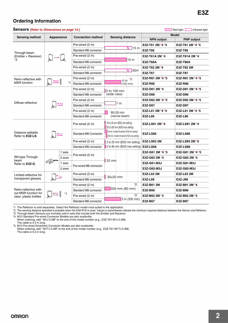
E3ZOrdering Information
Sensors [Refer to Dimensions on page 14.]
*1. The Reflector is sold separately. Select the Reflector model most suited to the application.*2. The sensing distance specified is possible when the E39-R1S is used. Values in parentheses indicate the minimum required distance between the Sensor and Reflector.*3. Through-beam Sensors are normally sold in sets that include both the Emitter and Receiver. *4. M12 Standard Pre-wired Connector Models are also availavble.
When ordering, add "-M1J 0.3M" to the end of the model number (e.g., E3Z-T61-M1J 0.3M).The cable is 0.3 m long.
*5. M12 Pre-wired Smartclick Connector Models are also availavble.When ordering, add "-M1TJ 0.3M" to the end of the model number (e.g., E3Z-T61-M1TJ 0.3M).The cable is 0.3 m long.
Sensing method Appearance Connection method Sensing distanceModel
NPN output PNP output
Through-beam(Emitter + Receiver) *3
Pre-wired (2 m) E3Z-T61 2M *4 *5 E3Z-T81 2M *4 *5
Standard M8 connector E3Z-T66 E3Z-T86
Pre-wired (2 m) E3Z-T61A 2M *4 E3Z-T81A 2M *4
Standard M8 connector E3Z-T66A E3Z-T86A
Pre-wired (2 m) E3Z-T62 2M *4 E3Z-T82 2M
Standard M8 connector E3Z-T67 E3Z-T87
Retro-reflective with MSR function *1
Pre-wired (2 m) E3Z-R61 2M *4 *5 E3Z-R81 2M *4 *5
Standard M8 connector E3Z-R66 E3Z-R86
Diffuse-reflective
Pre-wired (2 m) E3Z-D61 2M *4 E3Z-D81 2M *4 *5
Standard M8 connector E3Z-D66 E3Z-D86
Pre-wired (2 m) E3Z-D62 2M *4 *5 E3Z-D82 2M *4 *5
Standard M8 connector E3Z-D67 E3Z-D87
Pre-wired (2 m) E3Z-L61 2M *4 *5 E3Z-L81 2M *4 *5
Standard M8 connector E3Z-L66 E3Z-L86
Distance-settableRefer to E3Z-LS.
Pre-wired (2 m) E3Z-LS61 2M *4 E3Z-LS81 2M *4
Standard M8 Connector E3Z-LS66 E3Z-LS86
Pre-wired (2 m) E3Z-LS63 2M E3Z-LS83 2M *5
Standard M8 connector E3Z-LS68 E3Z-LS88
Slit-type Through-beamRefer to E3Z-G.
1 axisPre-wired (2 m)
E3Z-G61 2M *4 *5 E3Z-G81 2M *4 *5
2 axes E3Z-G62 2M *4 E3Z-G82 2M *4
1 axisPre-wired M8 connector
E3Z-G61-M3J E3Z-G81-M3J
2 axes E3Z-G62-M3J E3Z-G82-M3J
Limited-reflective for transparent glasses
Pre-wired (2 m) E3Z-L63 2M E3Z-L83 2M
Standard M8 connector E3Z-L68 E3Z-J88
Retro-reflective with-out MSR function for clear, plastic bottles
Pre-wired (2 m) *2 E3Z-B61 2M E3Z-B81 2M *4
Standard M8 connector E3Z-B66 E3Z-B86
Pre-wired (2 m) *2 E3Z-B62 2M *4 E3Z-B82 2M *4
Standard M8 connector E3Z-B67 E3Z-B87
Red light Infrared light
15 m
10 m
30m
4 m (100 mm)
*2
5 to 100 mm (wide view)
1 m
90±30 mm (narrow beam)
20 to 40 mm (BGS min setting)20 to 200 mm (BGS max setting)
40 min. Incident threshold (FGS min setting)
200 min. Incident threshold (FGS max setting)
2 to 20 mm (BGS min setting)2 to 80 mm (BGS max setting)
25 mm
30±20 mm
*1
500 mm (80 mm)
2 m (500 mm)
3
E3Z
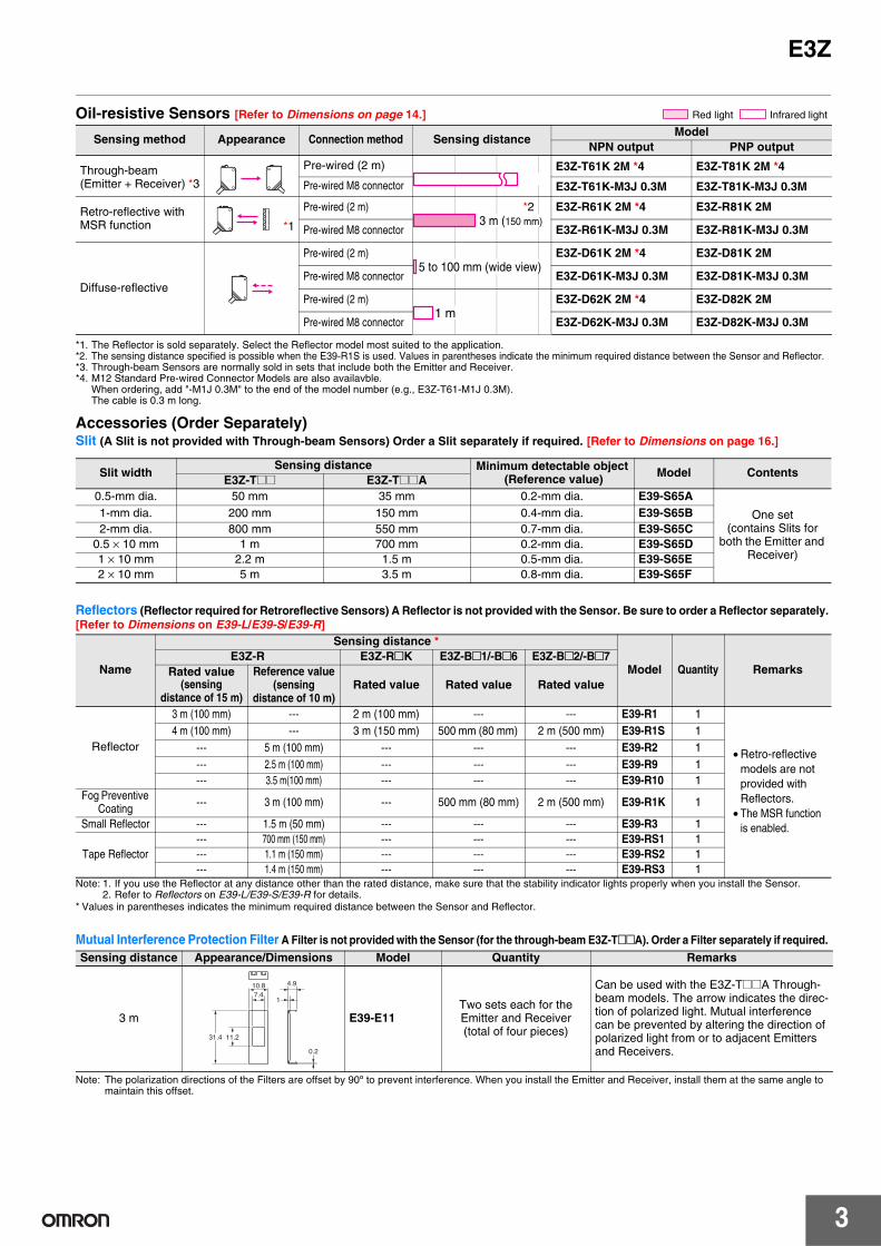
Oil-resistive Sensors [Refer to Dimensions on page 14.]
*1. The Reflector is sold separately. Select the Reflector model most suited to the application. *2. The sensing distance specified is possible when the E39-R1S is used. Values in parentheses indicate the minimum required distance between the Sensor and Reflector. *3. Through-beam Sensors are normally sold in sets that include both the Emitter and Receiver. *4. M12 Standard Pre-wired Connector Models are also availavble.
When ordering, add "-M1J 0.3M" to the end of the model number (e.g., E3Z-T61-M1J 0.3M).The cable is 0.3 m long.
Accessories (Order Separately)Slit (A Slit is not provided with Through-beam Sensors) Order a Slit separately if required. [Refer to Dimensions on page 16.]
Reflectors (Reflector required for Retroreflective Sensors) A Reflector is not provided with the Sensor. Be sure to order a Reflector separately. [Refer to Dimensions on E39-L/E39-S/E39-R]
Note: 1. If you use the Reflector at any distance other than the rated distance, make sure that the stability indicator lights properly when you install the Sensor.2. Refer to Reflectors on E39-L/E39-S/E39-R for details.
* Values in parentheses indicates the minimum required distance between the Sensor and Reflector.
Note: The polarization directions of the Filters are offset by 90º to prevent interference. When you install the Emitter and Receiver, install them at the same angle to maintain this offset.
Sensing method Appearance Connection method Sensing distanceModel
NPN output PNP output
Through-beam(Emitter + Receiver) *3
Pre-wired (2 m) E3Z-T61K 2M *4 E3Z-T81K 2M *4
Pre-wired M8 connector E3Z-T61K-M3J 0.3M E3Z-T81K-M3J 0.3M
Retro-reflective with MSR function *1
Pre-wired (2 m) *2 E3Z-R61K 2M *4 E3Z-R81K 2M
Pre-wired M8 connector E3Z-R61K-M3J 0.3M E3Z-R81K-M3J 0.3M
Diffuse-reflective
Pre-wired (2 m) E3Z-D61K 2M *4 E3Z-D81K 2M
Pre-wired M8 connector E3Z-D61K-M3J 0.3M E3Z-D81K-M3J 0.3M
Pre-wired (2 m) E3Z-D62K 2M *4 E3Z-D82K 2M
Pre-wired M8 connector E3Z-D62K-M3J 0.3M E3Z-D82K-M3J 0.3M
Red light Infrared light
15 m
3 m (150 mm)
5 to 100 mm (wide view)
1 m
Slit widthSensing distance Minimum detectable object
(Reference value) Model ContentsE3Z-T@@ E3Z-T@@A
0.5-mm dia. 50 mm 35 mm 0.2-mm dia. E39-S65A
One set (contains Slits for
both the Emitter and Receiver)
1-mm dia. 200 mm 150 mm 0.4-mm dia. E39-S65B2-mm dia. 800 mm 550 mm 0.7-mm dia. E39-S65C
0.5 × 10 mm 1 m 700 mm 0.2-mm dia. E39-S65D1 × 10 mm 2.2 m 1.5 m 0.5-mm dia. E39-S65E2 × 10 mm 5 m 3.5 m 0.8-mm dia. E39-S65F
Name
Sensing distance *
Model Quantity RemarksE3Z-R E3Z-R@K E3Z-B@1/-B@6 E3Z-B@2/-B@7
Rated value(sensing
distance of 15 m)
Reference value(sensing
distance of 10 m)Rated value Rated value Rated value
Reflector
3 m (100 mm) --- 2 m (100 mm) --- --- E39-R1 1
• Retro-reflectivemodels are notprovided withReflectors.
• The MSR function is enabled.
4 m (100 mm) --- 3 m (150 mm) 500 mm (80 mm) 2 m (500 mm) E39-R1S 1--- 5 m (100 mm) --- --- --- E39-R2 1--- 2.5 m (100 mm) --- --- --- E39-R9 1--- 3.5 m(100 mm) --- --- --- E39-R10 1
Fog Preventive Coating
--- 3 m (100 mm) --- 500 mm (80 mm) 2 m (500 mm) E39-R1K 1
Small Reflector --- 1.5 m (50 mm) --- --- --- E39-R3 1
Tape Reflector--- 700 mm (150 mm) --- --- --- E39-RS1 1--- 1.1 m (150 mm) --- --- --- E39-RS2 1--- 1.4 m (150 mm) --- --- --- E39-RS3 1
Sensing distance Appearance/Dimensions Model Quantity Remarks
3 m E39-E11Two sets each for the Emitter and Receiver(total of four pieces)
Can be used with the E3Z-T@@A Through-beam models. The arrow indicates the direc-tion of polarized light. Mutual interference can be prevented by altering the direction of polarized light from or to adjacent Emitters and Receivers.0.2
1
4.910.87.4
11.231.4
Mutual Interference Protection Filter A Filter is not provided with the Sensor (for the through-beam E3Z-T@@A). Order a Filter separately if required.

4
E3Z
Mounting Brackets A Mounting Bracket is not enclosed with the Sensor. Order a Mounting Bracket separately if required. [Refer to Dimensions on E39-L/E39-S/E39-R]
Note: 1. When using Through-beam models, order one bracket for the Receiver and one for the Emitter.2. Refer to Mounting Brackets on E39-L/E39-S/E39-R for details.
*1. Cannot be used for Standard Connector models with mounting surface on the bottom. In that case, use Pre-wired Connector models.*2. Cannot be used for Standard Connector models.
Sensor I/O Connectors (Sockets on One Cable End)(Models for Connectors and Pre-wired Connectors: A Connector is not provided with the Sensor. Be sure to order a Connector separately.)[Refer to Dimensions for XS3.]
Note: 1. When using Through-beam models, order one connector for the Receiver and one for the Emitter.2. Refer to Introduction to Sensor I/O Connectors/Sensor Controllers for details.
*1. The Sensor can be used in low-temperature environments (−25°C to −40°C). Do not use the Sensor in locations that are subject to oil.*2. The connector will not rotate after connecting.*3. The cable is fixed at an angle of 180° from the sensor emitter/receiver surface.
Appearance Model (material) Quantity Remarks Appearance Model (material) Quantity Remarks
E39-L153(SUS304) *1 1
Mounting Brackets
E39-L98(SUS304) *2 1 Metal Protective Cover
Bracket
E39-L104(SUS304) *1 1
E39-L150(SUS304) 1
(Sensor adjuster)
Easily mounted to the aluminum frame rails of conveyors and easily adjusted.
For left to right adjust-ment
E39-L43(SUS304) *2 1 Horizontal Mounting
Brackets
E39-L151(SUS304) 1
E39-L142(SUS304) *2 1 Horizontal Protective
Cover Bracket
E39-L44(SUS304) 1 Rear Mounting Bracket
E39-L144(SUS304) *2 1
Compact Protective Cover Bracket (For E3Z only)
Size Cable Appearance Cable type Model
M8
Standard
2 m
4-wire
XS3F-M421-402-A5 m XS3F-M421-405-A2 m XS3F-M422-402-A5 m XS3F-M422-405-A
PUR (Polyure-thane) cable *1
2 m XS3F-M421-402-L5 m XS3F-M421-405-L2 m XS3F-M422-402-L5 m XS3F-M422-405-L
Vibration-proof robot cable
2 m XS3F-M421-402-R5 m XS3F-M421-405-R2 m XS3F-M422-402-R5 m XS3F-M422-405-R
Straight *2
L-shaped *2 *3
Straight *2
L-shaped *2 *3
Straight *2
L-shaped *2 *3

5
E3ZRatings and Specifications
*1. Values in parentheses indicate the minimum required distances between the Sensors and Reflectors.*2. Plastic bottles must pass with the minimum clearance of 500 mm.
Sensing method Through-beam Retro-reflective with MSR function Diffuse-reflective (Narrow-
beam Models)
Model
NPNout-put
Pre-wired E3Z-T61 E3Z-T62 E3Z-T61A E3Z-R61 E3Z-D61 E3Z-D62 E3Z-L61
Connector (M8) E3Z-T66 E3Z-T67 E3Z-T66A E3Z-R66 E3Z-D66 E3Z-D67 E3Z-L66
PNPout-put
Pre-wired E3Z-T81 E3Z-T82 E3Z-T81A E3Z-R81 E3Z-D81 E3Z-D82 E3Z-L81
Item Connector (M8) E3Z-T86 E3Z-T87 E3Z-T86A E3Z-R86 E3Z-D86 E3Z-D87 E3Z-L86
Sensing distance 15 m 30 m 10 m
4 m (100 mm) *1(when using E39-R1S)3 m (100 mm) *1(when using E39-R1)
100 mm (white paper: 100 × 100 mm)
1 m (white paper: 300 × 300 mm)
90 + 30 mm (white paper, 100 x 100 mm)
Spot diameter (reference value) ---
(2.5 dia. and sensing dis-tance of 90 mm)
Standard sensing object Opaque: 12-mm dia. min. Opaque: 75-mm dia. min. ---
Minimum detectable object (reference value) ---
0.1 mm (cop-per wire)
Differential travel --- 20% max. of setting distanceRefer to Engi-neering data on page 8.
Directional angle Both emitter and receiver: 3 to 15° 2 to 10° ---
Light source (wavelength) Infrared LED (870 nm) Red LED(660 nm) Red LED (660 nm) Infrared LED (860 nm) Red LED
(650 nm)
Current consumption 35 mA max. (Emitter: 15 mA max., Receiv-er: 20 mA max.) 30 mA max.
Protection circuitsReversed power supply polarity protection, Output short-circuit protection, and Re-versed output polarity protection
Reversed power supply polarity protection, Output short-circuit protection, Mutual interference prevention, and Reversed output polarity protection
Response timeOperate or reset: 1 ms max.
Operate or reset: 2 ms max.
Operate or reset: 1 ms max.
Degree of protection IEC, IP67
Connection method Pre-wired cable (standard length: 2 m and 0.5 m), Connector (M8)
Weight(packedstate)
Pre-wired cable (2 m) Approx. 120 g Approx. 65 g
Connector Approx. 30 g Approx. 20 g
MaterialCase PBT (polybutylene terephthalate)
Lens Modified polyarylate Methacrylic resin Modified polyarylate
Sensing method Retro-reflective for clear, plastic bottles (without MSR function)
ModelNPN output E3Z-B61 E3Z-B66 E3Z-B62 E3Z-B67
Item PNP output E3Z-B81 E3Z-B86 E3Z-B82 E3Z-B87
Sensing distance 500 mm (80 mm) *1 (using E39-R1S) 2 m (500 mm) *1 *2 (using E39-R1S)
Standard sensing objectOpaque materials, 75mm dia. min.(Standard detectable object :glass Cylinder 15mm dia. thickness 1.1mm length 50mm, and the transmis-sion factor 92% or less in wave length 660nm)
Light source (wavelength) Red LED (660 nm)
Current consumption 30 mA max.
Protection circuits Reversed power supply polarity protection, Output short-circuit protection, Mutual interference prevention, and Reversed output polarity protection
Response time Operate or reset: 1 ms max.
Degree of protection IEC, IP67
Connection method Pre-wired cable (standard length: 2 m and 0.5 m) Connector (M8, 4 pins) Pre-wired cable (standard
length: 2 m and 0.5 m) Connector (M8, 4 pins)
Weight (packed state)
Pre-wired cable (2 m) Approx. 65 g
Standard Connector Approx. 20 g
MaterialCase PBT (polybutylene terephthalate)
Lens Modified polyarylate

6
E3Z
Sensing method Transparent glass Limited-reflective (for transparent object detection )
Model NPN output E3Z-L63 E3Z-L68
Item PNP output E3Z-L83 E3Z-L88
Sensing distance 30±20 mm (transparent glasses 100 × 100 mm)
Spot diameter (reference value) 2-mm dia. min. (at sensing distance of 30 mm)
Minimum detectable object (reference value) 0.1 mm dia. (copper wire)
Light source (wavelength) Red LED (660 nm)
Current consumption 30 mA max.
Protection circuits Power supply reverse polarity protection, Output short-circuit protection, Mutual interference prevention,Reverse output polarity protection
Response time Operate or reset: 1 ms max.
Degree of protection IEC, IP67
Connection method Pre-wired (standard length: 2 m) M8 connector
Weight (packed state)
Pre-wired cable (2 m) Approx. 65 g
Standard Connector Approx. 20 g
MaterialCase PBT (polybutylene terephthalate)
Lens Modified polyarylate

7
E3Z
Oil-resistant
* Values in parentheses indicate the minimum required distance between the Sensor and Reflector.
Common
* The ambient temperature range during operation for connector models depends on the model. For the E3Z-T66/T86/R66/R86, the range is −40°C to 55°C. For the E3Z-D66/D86/D67/D87, the range is −30°C to 55°C. For other connector models, the range is −25°C to −55°C. The sensing distance for Retro-reflective Models (E3Z-R66/R86) between −40°C to −25°C, however, will be as follows (not the values in the table): With E39-R1S: 3 m (100 mm), With E39-R1: 2 m (100 mm). Also, use the XS3F-M42@-4@@-L Sensor I/O Connector (PUR cable) for applications between −25°C to −40°C. (Refer to page 4.)
Sensing method Through-beam Retro-reflective Diffuse-reflective
Model
NPNout-put
Pre-wired Models E3Z-T61K E3Z-R61K E3Z-D61K E3Z-D62K
M8 Pre-wired connector E3Z-T61K-M3J E3Z-R61K-M3J E3Z-D61K-M3J E3Z-D62K-M3J
PNPout-put
Pre-wired Models E3Z-T81K E3Z-R81K E3Z-D81K E3Z-D82K
Item M8 Pre-wired connector E3Z-T81K-M3J E3Z-R81K-M3J E3Z-D81K-M3J E3Z-D82K-M3J
Sensing distance 15 m
3 m (150 mm) * (when using E39-R1S)2 m (100 mm) * (when using E39-R1)
100 mm (white paper: 100 × 100 mm)
1 m (white paper: 300 × 300 mm)
Standard sensing object Opaque: 12-mm dia. min. Opaque: 75-mm dia. min. ---
Differential travel --- 20% max. of setting distance
Directional angle Both emitter and receiver: 3 to 15° 2 to 10° ---
Light source (wavelength) Infrared LED (870 nm) Red LED (660 nm) Infrared LED (860 nm)
Current consumption35 mA max. (Emitter: 15 mA max., Receiver: 20 mA max.)
30 mA max.
Protection circuits
Reversed power supply polarity protection, Output short-circuit protection, and Reversed output po-larity protection
Reversed power supply polarity protection, Output short-circuit protection, Mutual in-terference prevention, and Reversed output polarity protection
Response time Operate or reset: 1 ms max.
Degree of protection IP67 (IEC), Oil resistant models: IP67 (IEC) (in-house standards: oilproof), excluding cables and connectors
Connection method Pre-wired cable (standard length: 2 m), M8 Pre-wired Connector
Weight(packedstate)
Pre-wired cable (2 m) Approx. 120 g Approx. 65 g
Connector (M8, 4 pins) Approx. 50 g Approx. 30 g
MaterialCase PBT (polybutylene terephthalate)
Lens Modified polyarylate Methacrylic resin Modified polyarylate
Power supply voltage 12 to 24 VDC±10%, ripple (p-p): 10% max.
Control output
Load power supply voltage: 26.4 VDC max., Load current: 100 mA max.Residual voltage: Load current of less than 10 mA: 1 V max.
Load current of 10 to 100 mA: 2 V max.Open collector output (NPN/PNP depending on model)Light-ON/Dark-ON selectable
Sensitivity adjustment One-turn adjuster
Ambient illumination (Receiver side) Incandescent lamp: 3,000 lx max.Sunlight: 10,000 lx max.
Ambient temperature range Operating: −25 to 55°C, Some connector models: −40°C to 55°C * (with no icing or condensation)Storage: −40 to 70°C (with no icing or condensation)
Ambient humidity range Operating: 35% to 85%, Storage: 35% to 95% (with no condensation)
Insulation resistance 20 MΩ min. at 500 VDC
Dielectric strength 1,000 VAC, 50/60 Hz for 1 min
Vibration resistance Destruction: 10 to 55 Hz, 1.5 mm double amplitude for 2 hours each in X, Y, and Z directions
Shock resistance Destruction: 500 m/s2 3 times each in X, Y, and Z directions
IndicatorOperation indicator (orange)Stability indicator (green)Through-beam Emitter has power indicator (orange) only.
Accessories Instruction manual (Neither Reflectors nor Mounting Brackets are provided with any of the above models.)
8
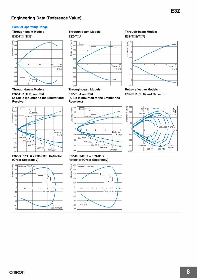
E3ZEngineering Data (Reference Value)
Parallel Operating Range
Through-beam Models Through-beam Models Through-beam Models
E3Z-T@1(T@6) E3Z-T@A E3Z-T@2(T@7)
Through-beam Models Through-beam Models Retro-reflective Models
E3Z-T@1(T@6) and Slit(A Slit is mounted to the Emitter and Receiver.)
E3Z-T@A and Slit(A Slit is mounted to the Emitter and Receiver.)
E3Z-R@1(R@6) and Reflector
E3Z-B@1/B@6 + E39-R1S Reflector (Order Separately)
E3Z-B@2/B@7 + E39-R1SReflector (Order Separately)
1000
800
600
400
200
0
−200
−400
−600
−800
−1000
40302010Distance
X (m)
Y
X
Dis
tanc
e Y
(m
m)
1000
800
600
400
200
0
−200
−400
−600
−800
−1000
40302010
Y
X
Distance X (m)
Dis
tanc
e Y
(m
m)
2.0
1.5
1.0
0.5
0
−0.5
−1.0
−1.5
−2.0
40302010Distance
X (m)
Dis
tanc
e Y
(m
m)
Y
X
250
200
150
100
50
0
−50
−100
−150
−200
−250
5 4 3 2 1
E39-S65B
E39-S65C
E39-S65D
E39-S65E E39-S65F
Distance X (m)
Dis
tanc
e Y
(m
m) 200
150
100
50
0
−50
−200
−150
−100
5 4 3 2 1
E39-S65B
E39-S65C
E39-S65D E39-S65E
E39-S65F
Distance X (m)
Dis
tanc
e Y
(m
m)
Y
X
Y
X
200
150
100
50
0
−50
−100
−150
−200
8642
E39-R9
E39-R1SE39-R1
E39-R10
E39-R2
E39-R1K
E39-R3
Dis
tanc
e Y
(m
m)
Distance X (m)
30.5 1 1.5 2 2.5
Y
X
−50
−40
−30
−20
−10
0
10
20
30
40
50
Dis
tanc
e Y
(m
m)
Reflector: E39-R1S
500-mm type
Distance X (m)
−100
−80
−60
−40
−20
0
20
40
60
80
100
Dis
tanc
e Y
(m
m)
4.50.5 1 1.5 2 2.5 3 3.5 4
Reflector: E39-R1S
Distance X (m)
2-m type
Y
X

9
E3Z
Operating Range
Diffuse-reflective Models Diffuse-reflective Models Narrow-beam Reflective Models
E3Z-D@1(D@6) E3Z-D@2(D@7) E3Z-L@1(L@6)
Excess Gain vs. Set Distance
Through-beam Models Retro-reflective Models Diffuse-reflective Models
E3Z-T@1(T@6)/-T@A/-T@2(T@7) E3Z-R@1(R@6) and Reflector E3Z-D@1(D@6)
Diffuse-reflective Models Narrow-beam Reflective Models Limited reflective Models
E3Z-D@2(D@7) E3Z-L@1(L@6) E3Z-L@3(L@8)
30
20
10
0
−10
−20
−30
250150 20010050
Y
X
Sensing object: 100 × 100 mm white paper
Dis
tanc
e Y
(m
m)
Distance X (m)
80
60
40
20
0
−20
−40
−60
−80
1.61.0 1.20.6 1.40.80.2 0.4
Y
X
Sensing object: 300 × 300 mm white paper
Dis
tanc
e Y
(m
m)
Distance X (m)
Y
X
10
8
6
4
2
0
−2
−4
−6
−8
−10
Sensing object: 100 × 100 mm white paper
50 100 150200
250
Dis
tanc
e Y
(m
m)
DistanceX (m)
100
10
1
0.1 0 10 20 30 40 50 70 60 80
E3Z-T@A
E3Z-T@2 (T@7)
E3Z-T@1 (T@6)
Exc
ess
gain
rat
io
Distance (m)
100
10
1
0.1106 8420
E39-R1S
E39-R1
E39-R10
E39-R2
E39-R1K
E39-R3
E39-R9
Exc
ess
gain
rat
io
Distance (m)
1007050
30
1075
3
10.70.5
0.3
0.10 50 100 150 200 250 300 350
Exc
ess
gain
rat
io
Distance (m)
Operating level
Sensing object: 100 × 100 mm white paper
1007050
30
1075
3
10.70.5
0.3
0.10 0.5 1 1.5 2.52 3
Exc
ess
gain
rat
io
Distance (m)
Operating level
Sensing object: 300 × 300 mm white paper 1007050
30
1075
3
10.70.5
0.3
0.10 50 100 150 200 250 300 350
Exc
ess
gain
rat
io
Distance (m)
Operating level
SUS
White paper
Glass
1007050
30
1075
3
10.70.5
0.3
0.10 20 40 60 80 100 120
Exc
ess
gain
rat
io
Distance (m)
Operating level

10
E3Z
Excess Gain vs. Set Distance
E3Z-B@1/B@6 + E39-R1SReflector (Order Separately)
E3Z-B@2/B@7 + E39-R1SReflector (Order Separately)
Sensing Object Size vs. Sensing Distance
Diffuse-reflective Models Diffuse-reflective Models Narrow-beam Reflective Models
E3Z-D@1(D@6) E3Z-D@2(D@7) E3Z-L@1(L@6)
Spot Diameter vs. Sensing Distance Differential Travel vs. Sensing Distance
Narrow-beam Reflective Models Narrow-beam Reflective Models
E3Z-L@1(L@6) E3Z-L@1(L@6)
0.1
1
10
100
0.5 1 1.5 2 2.5 3
Exc
ess
gain
rat
io
500-mm type
Distance (m)
0.1
1
10
100
0.5 1 1.5 2 2.5 3 3.5 4 4.5 5
Exc
ess
gain
rat
io
Distance (m)
2-m type
d
d
350
300
250
200
150
100
50
350300250200150100500
Side length (one side) of sensing object: d (mm)
Black paper
SUS (glossy surface)
Dis
tanc
e (m
m)
White paper d
d
4.5
4
3.5
3
2.5
2
1.5
1
0.5
350300250200150100500Side length (one side) of sensing object: d (mm)
Black paper
SUS (glossy surface)D
ista
nce
(m)
White paper
d
d
300
250
200
150
100
50
10010 20 307.51 2 3 50
Side length (one side) of sensing object: d (mm)
Dis
tanc
e (m
)
White paper
4.0
3.5
3.0
2.5
2.0
1.5
1.0
0.5
1601401208040 10060200
Distance (mm)
Spo
t dia
met
er (
mm
) 30
25
20
15
10
5
15010075 125500
Distance (mm)
Diff
eren
tial t
rave
l (m
m)

11
E3ZI/O Circuit Diagrams
NPN Output
PNP Output
* Models numbers for Through-beam Sensors (E3Z-T@@) are for sets that include both the Emitter and Receiver. The model number of the Emitter is expressed by adding "-L" to the set model number (example: E3Z-T61-L 2M), the model number of the Receiver, by adding "-D" (example: E3Z-T61-D 2M.) Refer to Ordering Information to confirm model numbers for Emitter and Receivers.
Model* Operation mode Timing charts Operation
selector Output circuit
E3Z-T61(K)E3Z-T66E3Z-T62E3Z-T67E3Z-T61AE3Z-T66AE3Z-R61(K)E3Z-R66E3Z-D61(K)E3Z-D66E3Z-D62(K)E3Z-D67E3Z-L61E3Z-L66E3Z-B61E3Z-B66E3Z-B62E3Z-B67E3Z-L63E3Z-L68
Light-ON L side(LIGHT ON)
Dark-ON D side(DARK ON)
Model* Operation mode Timing charts Operation
selector Output circuit
E3Z-T81(K)E3Z-T86E3Z-T82E3Z-T87E3Z-T81AE3Z-T86AE3Z-R81(K)E3Z-R86E3Z-D81(K)E3Z-D86E3Z-D82(K)E3Z-D87E3Z-L81E3Z-L86E3Z-B81E3Z-B86E3Z-B82E3Z-B87E3Z-L83E3Z-L88
Light-ON L side(LIGHT ON)
Dark-ON D side(DARK ON)
Incident light
No incident light
ON
OFF
ON
OFF
Operate
Reset
Operationindicator (orange)
(Between brown (1) and black (4) leads)
Output transistor
Load(e.g., relay)
Connector Pin Arrangement
Pin 2 is not used.
4
1
2 43
3
1 12 to 24 VDC Br o w n
Bla c k (Control output)
Blue
100 mA max.
Ope r ation indicator Stability
indicator (Green) (O r ange )
0 V
Z D
Load (Rel a y )
Photo - elect r ic Sensor main circuit
Through-beam Receivers, Retro-reflective Models, Diffuse-reflective Models, Limited reflective Models.
Incident light
No incident light
ON
OFF
ON
OFF
Operate
Reset
Operationindicator (orange)
(Between brown (1) and black (4) leads)
Output transistor
Load(e.g., relay)
1
2 43
3
1 Power indicator (orange)
Connector Pin Arrangement
Pins 2 and 4 are not used.
12 to 24 VDC
Brown
Blue
Photo- electric Sensor main circuit
Through-beam Emitter
Incident light
No incident light
ON
OFF
ON
OFF
Operate
Reset
Operationindicator (orange)
(Between blue (3) and black (4) leads)
Output transistor
Load(e.g., relay)
4
1
2 43
1
3 0 V
ZD
Connector Pin Arrangement
Pin 2 is not used.
12 to 24 VDC Brown
Black
(Control output)
Blue
100 mA max.
Operation indicator Stability
indicator (Green) (Orange)
Load (Relay)
Photo-electric Sensor main circuit
Through-beam Receivers, Retro-reflective Models, Diffuse-reflective Models, Limited reflective Models.
Incident light
No incident light
ON
OFF
ON
OFF
Operate
Reset
Operationindicator (orange)
(Between blue (3) and black (4) leads)
Output transistor
Load(e.g., relay)
1
2 43
3
1Power indicator (orange) Connector Pin Arrangement
Pins 2 and 4 are not used.
12 to 24 VDC
Brown
Blue
Photo- electric Sensor Main Circuit
Through-beam Emitter
12
E3Z
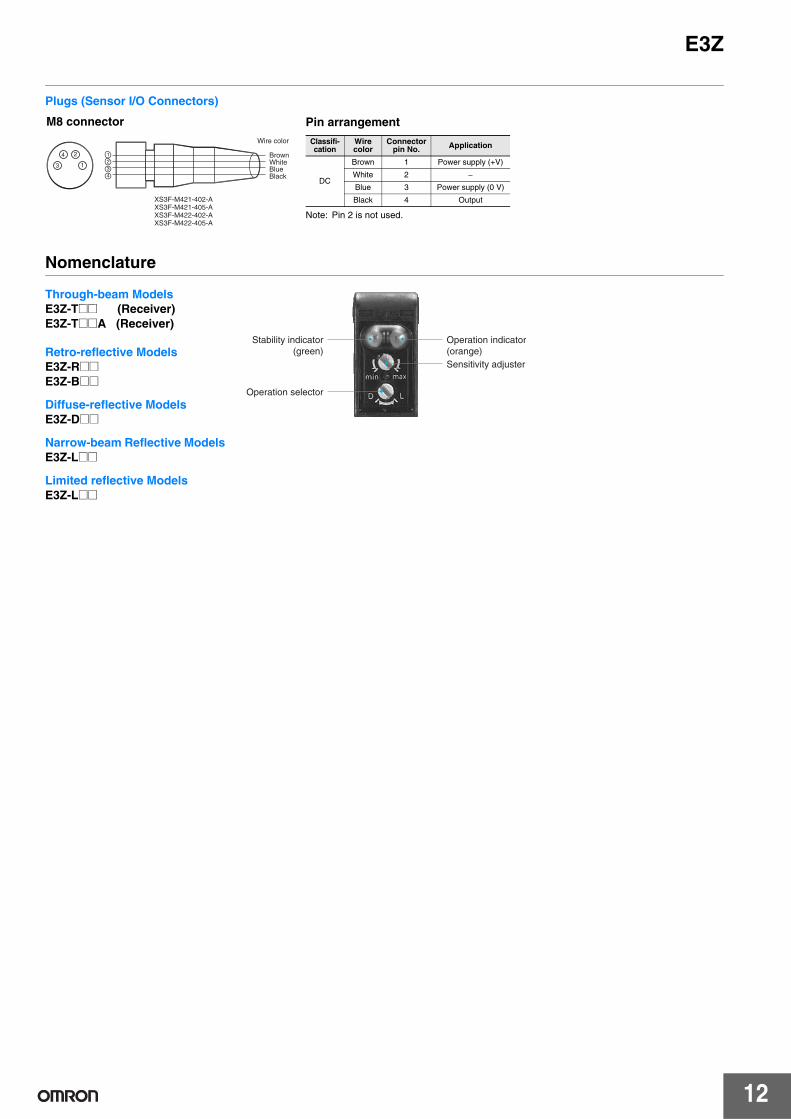
Plugs (Sensor I/O Connectors)
Nomenclature
24
13
1234
BrownWhite Blue Black
Wire color
XS3F-M421-402-AXS3F-M421-405-AXS3F-M422-402-AXS3F-M422-405-A
Pin arrangement
Note: Pin 2 is not used.
Classifi-cation
Wirecolor
Connector pin No. Application
DC
Brown 1 Power supply (+V)
White 2 −Blue 3 Power supply (0 V)
Black 4 Output
M8 connector
Through-beam ModelsE3Z-T@@ (Receiver)E3Z-T@@A (Receiver)
Retro-reflective ModelsE3Z-R@@E3Z-B@@
Diffuse-reflective ModelsE3Z-D@@
Narrow-beam Reflective ModelsE3Z-L@@
Limited reflective ModelsE3Z-L@@
Stability indicator(green)
Operation selector
Operation indicator(orange)Sensitivity adjuster
13
E3ZSafety Precautions
Refer to Warranty and Limitations of Liability.
This product is not designed or rated for ensuring safety of persons either directly or indirectly.Do not use it for such purposes.
Do not use the product in atmospheres or environments that exceed product ratings.
● Wiring
M8 Metal Connector• Be sure to connect or disconnect the metal connector after turning
OFF the Sensor.• Hold the connector cover to connect or disconnect the metal
connector.• Secure the connector cover by hand. Do not use any pliers,
otherwise the connector may be damaged.• The proper tightening torque range is between 0.3 and 0.4 N·m. Be
sure to tighten the connector securely, otherwise the specified degree of protection may not be maintained or the connector may be disconnected due to vibration.
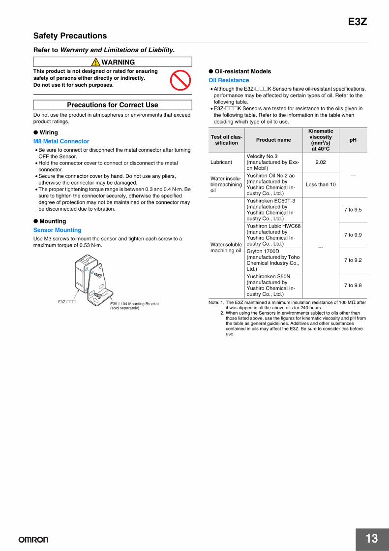
● Mounting
Sensor MountingUse M3 screws to mount the sensor and tighten each screw to a maximum torque of 0.53 N·m.
● Oil-resistant Models
Oil Resistance• Although the E3Z-@@@K Sensors have oil-resistant specifications,
performance may be affected by certain types of oil. Refer to the following table.
• E3Z-@@@K Sensors are tested for resistance to the oils given in the following table. Refer to the information in the table when deciding which type of oil to use.
Note: 1. The E3Z maintained a minimum insulation resistance of 100 MΩ after it was dipped in all the above oils for 240 hours.
2. When using the Sensors in environments subject to oils other than those listed above, use the figures for kinematic viscosity and pH from the table as general guidelines. Additives and other substances contained in oils may affect the E3Z. Be sure to consider this before use.
WARNING
Precautions for Correct Use
E3Z-@@@ E39-L104 Mounting Bracket(sold separately)
Test oil clas-sification Product name
Kinematic viscosity(mm2/s)at 40°C
pH
LubricantVelocity No.3(manufactured by Exx-on Mobil)
2.02
---Water insolu-ble machining oil
Yushiron Oil No.2 ac(manufactured by Yushiro Chemical In-dustry Co., Ltd.)
Less than 10
Water soluble machining oil
Yushiroken EC50T-3(manufactured by Yushiro Chemical In-dustry Co., Ltd.)
---
7 to 9.5
Yushiron Lubic HWC68(manufactured by Yushiro Chemical In-dustry Co., Ltd.)
7 to 9.9
Gryton 1700D(manufactured by Toho Chemical Industry Co., Ltd.)
7 to 9.2
Yushironken S50N(manufactured by Yushiro Chemical In-dustry Co., Ltd.)
7 to 9.8
14
E3ZDimensions
Sensors
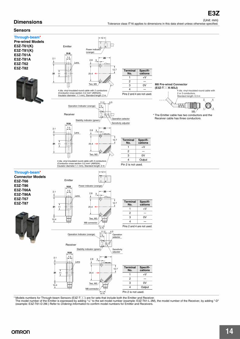
* Models numbers for Through-beam Sensors (E3Z-T@@) are for sets that include both the Emitter and Receiver.The model number of the Emitter is expressed by adding "-L" to the set model number (example: E3Z-T61-L 2M), the model number of the Receiver, by adding "-D" (example: E3Z-T61-D 2M.) Refer to Ordering Information to confirm model numbers for Emitter and Receivers.
(Unit: mm)Tolerance class IT16 applies to dimensions in this data sheet unless otherwise specified.
Through-beam*Pre-wired ModelsE3Z-T61(K)E3Z-T81(K)E3Z-T61AE3Z-T81AE3Z-T62E3Z-T82
2020
12
32.8
25.4
12.7
4 dia. vinyl-insulated round cable with 2 conductors (Conductor cross section: 0.2 mm2 (AWG24), Insulator diameter: 1.1 mm), Standard length: 2 m
Two, M3
Power indicator (orange)
Emitter
Lens
11
2.1
3131
10.810.8
7.2
Pins 2 and 4 are not used.
Terminal No.
Specifi-cations
1 +V2 ---3 0V4 ---
M8 Pre-wired Connector(E3Z-T@@K-M3J)
4 dia. vinyl-insulated round cable with 2 or 3 conductors, Standard length: 0.3 m
M8
2 4
1 3
* The Emitter cable has two conductors and the Receiver cable has three conductors.
202032.8
25.4
12.7
4 dia. vinyl-insulated round cable with 3 conductors (Conductor cross section: 0.2 mm2 (AWG24), Insulator diameter:1.1 mm), Standard length: 2 m
Two, M3
4.511.2
Stability indicator (green)
Operation Indicator (orange) 7.5
Sensitivity adjuster
Operation selector
Receiver
Lens
11
2.1
3131
10.810.8
7.2
Pin 2 is not used.
Terminal No.
Specifi-cations
1 +V
2 ---
3 0V
4 Output
Through-beam*Connector ModelsE3Z-T66E3Z-T86E3Z-T66AE3Z-T86AE3Z-T67E3Z-T87
M8 connector
10.4 Two, M3
Lens
11
Power indicator (orange)
9.75
Emitter
12
20202.1
12.7
3131
10.810.8
7.232.8
25.4
Pins 2 and 4 are not used.
Terminal No.
Specifi-cations
1 +V
2 ---
3 0V
4 ---
M8 connector
9.75
Lens
Stability indicator (green)
Operation Indicator (orange)
Sensitivity adjuster
Operation selector
Receiver
Two, M3
2.8
25.4
4.511.2
7.5
12.7
2020
10.810.8
7.2
10.4
11
2.1
3131
3
Pin 2 is not used.
Terminal No.
Specifi-cations
1 +V
2 ---
3 0V
4 Output

15
E3Z
Retro-reflective ModelsPre-wired ModelsE3Z-R61(K) E3Z-B61E3Z-R81(K) E3Z-B81E3Z-D61(K) E3Z-B62E3Z-D81(K) E3Z-B82E3Z-D62(K) E3Z-L63E3Z-D82(K) E3Z-L83E3Z-L61E3Z-L81 2.8
25.4
4 dia. vinyl-insulated round cable with 3conductors (Conductor cross section:0.2 mm2 (AWG24), Insulator diameter:1.1 mm), Standard length: 2 m
Stability indicator (green)
Two, M3
Sensitivity adjuster
Operation selector
Operation Indicator (orange)
2.1
3131
Receiver Lens 7 dia.
EmitterLens 7 dia.
2020
16.7
10.810.8
32.8
4.511.2
7.5
25.48
Terminal No.
Specifica-tions
1 +V
2 ---
3 0V
4 Output
M8 Pre-wired Connector (E3Z-T@@K-M3J)
4 dia. vinyl-insulated round cable with 3 conductors, Standard length: 0.3 m
M8
2 4
1 3
Retro-reflective ModelsConnector ModelsE3Z-R66 E3Z-B66E3Z-R86 E3Z-B86E3Z-D66 E3Z-B67E3Z-D86 E3Z-B87E3Z-D67 E3Z-L68E3Z-D87 E3Z-L88E3Z-L66E3Z-L86
Stability indicator (green)
Two, M3
9.75
Receiver Lens 7 dia.
EmitterLens 7 dia.
Sensitivity adjuster
M8 connector
Operation selector
Operation Indicator (orange)
2020
16.7
10.810.8
10.4
2.1
3131
2.8
25.4
4.511.2
7.5
3
8
Terminal No.
Specifica-tions
1 +V
2 ---
3 0V
4 Output
Note: The lens for the E3Z-D@1/D@6/L@@/B@@ is red. The lens for the E3Z-D@2/D@7 is black.

16
E3Z
Accessories (Order Separately)
Mounting Brackets
Refer to E39-R for details.
Sensor I/O Connectors
Refer to XS3@ for details.
SlitsE39-S65AE39-S65BE39-S65C
A
32.232.2
20.220.2
0.2-mm-thick
10.410.4
12.7
Model Size A MaterialE39-S65A 0.5 dia. SUS301
stainless steel
E39-S65B 1.0 dia.E39-S65C 2.0 dia.
SlitsE39-S65DE39-S65EE39-S65F
Model Size A MaterialE39-S65D 0.5 SUS301
stainless steel
E39-S65E 1.0E39-S65F 2.0
A
32.232.2 10
0.2-mm-thick
10.410.4
20.220.2
12.7
SlitsE39-L44
16.2
19.5
14.18.7
2727
31.231.2
3636
3
3
1.8
18
23.2
26.2
20°
(Mounting dimensions)SlitsE39-L104
6.7
7.0
1
4.5 6 2929
17.8
26.626.6
12.4
R20 14°
21.5
3939
10°
8.8
(Mounting dimensions)

Terms and Conditions Agreement
Read and understand this catalog. Please read and understand this catalog before purchasing the products. Please consult your OMRON representative if you have any questions or comments.
Warranties. (a) Exclusive Warranty. Omron’s exclusive warranty is that the Products will be free from defects in materials and workmanshipfor a period of twelve months from the date of sale by Omron (or such other period expressed in writing by Omron). Omrondisclaims all other warranties, express or implied.(b) Limitations. OMRON MAKES NO WARRANTY OR REPRESENTATION, EXPRESS OR IMPLIED, ABOUTNON-INFRINGEMENT, MERCHANTABILITY OR FITNESS FOR A PARTICULAR PURPOSE OF THE PRODUCTS. BUYERACKNOWLEDGES THAT IT ALONE HAS DETERMINED THAT THEPRODUCTS WILL SUITABLY MEET THE REQUIREMENTS OF THEIR INTENDED USE.Omron further disclaims all warranties and responsibility of any type for claims or expenses based on infringement by theProducts or otherwise of any intellectual property right. (c) Buyer Remedy. Omron’s sole obligation hereunder shall be, atOmron’s election, to (i) replace (in the form originally shipped with Buyer responsible for labor charges for removal orreplacement thereof) the non-complying Product, (ii) repair the non-complying Product, or (iii) repay or credit Buyer an amountequal to the purchase price of the non-complying Product; provided that in no event shall Omron be responsible for warranty,repair, indemnity or any other claims or expenses regarding the Products unless Omron’s analysis confirms that the Productswere properly handled, stored, installed and maintained and not subject to contamination, abuse, misuse or inappropriatemodification. Return of any Products by Buyer must be approved in writing by Omron before shipment. Omron Companies shallnot be liable for the suitability or unsuitability or the results from the use of Products in combination with any electrical orelectronic components, circuits, system assemblies or any other materials or substances or environments. Any advice,recommendations or information given orally or in writing, are not to be construed as an amendment or addition to the abovewarranty.See http://www.omron.com/global/ or contact your Omron representative for published information.
Limitation on Liability; Etc. OMRON COMPANIES SHALL NOT BE LIABLE FOR SPECIAL, INDIRECT, INCIDENTAL, OR CONSEQUENTIAL DAMAGES, LOSS OF PROFITS OR PRODUCTION OR COMMERCIAL LOSS IN ANY WAY CONNECTED WITH THE PRODUCTS, WHETHER SUCH CLAIM IS BASED IN CONTRACT, WARRANTY, NEGLIGENCE OR STRICT LIABILITY. Further, in no event shall liability of Omron Companies exceed the individual price of the Product on which liability is asserted.
Suitability of Use. Omron Companies shall not be responsible for conformity with any standards, codes or regulations which apply to the combination of the Product in the Buyer’s application or use of the Product. At Buyer’s request, Omron will provide applicable third party certification documents identifying ratings and limitations of use which apply to the Product. This information by itself is not sufficient for a complete determination of the suitability of the Product in combination with the end product, machine, system, or other application or use. Buyer shall be solely responsible for determining appropriateness of the particular Product with respect to Buyer’s application, product or system. Buyer shall take application responsibility in all cases. NEVER USE THE PRODUCT FOR AN APPLICATION INVOLVING SERIOUS RISK TO LIFE OR PROPERTY OR IN LARGE QUANTITIES WITHOUT ENSURING THAT THE SYSTEM AS A WHOLE HAS BEEN DESIGNED TO ADDRESS THE RISKS, AND THAT THE OMRON PRODUCT(S) IS PROPERLY RATED AND INSTALLED FOR THE INTENDED USE WITHIN THE OVERALL EQUIPMENT OR SYSTEM.
Programmable Products. Omron Companies shall not be responsible for the user’s programming of a programmable Product, or any consequence thereof.
Performance Data. Data presented in Omron Company websites, catalogs and other materials is provided as a guide for the user in determining suitability and does not constitute a warranty. It may represent the result of Omron’s test conditions, and the user must correlate it to actual application requirements. Actual performance is subject to the Omron’s Warranty and Limitations of Liability.
Change in Specifications. Product specifications and accessories may be changed at any time based on improvements and other reasons. It is our practice to change part numbers when published ratings or features are changed, or when significant construction changes are made. However, some specifications of the Product may be changed without any notice. When in doubt, special part numbers may be assigned to fix or establish key specifications for your application. Please consult with your Omron’s representative at any time to confirm actual specifications of purchased Product.
Errors and Omissions. Information presented by Omron Companies has been checked and is believed to be accurate; however, no responsibility is assumed for clerical, typographical or proofreading errors or omissions.

OMRON CANADA, INC. • HEAD OFFICEToronto, ON, Canada • 416.286.6465 • 866.986.6766 • www.omron247.com
OMRON ELECTRONICS DE MEXICO • HEAD OFFICEMéxico DF • 52.55.59.01.43.00 • 01-800-226-6766 • [email protected]
OMRON ELECTRONICS DE MEXICO • SALES OFFICEApodaca, N.L. • 52.81.11.56.99.20 • 01-800-226-6766 • [email protected]
OMRON ELETRÔNICA DO BRASIL LTDA • HEAD OFFICESão Paulo, SP, Brasil • 55.11.2101.6300 • www.omron.com.br
OMRON ARGENTINA • SALES OFFICECono Sur • 54.11.4783.5300
OMRON CHILE • SALES OFFICESantiago • 56.9.9917.3920
OTHER OMRON LATIN AMERICA SALES54.11.4783.5300
Authorized Distributor:
E88I-E-01 rev18 05/17 Note: Specifications are subject to change. © 2017 Omron. All Rights Reserved. Printed in U.S.A.
Printed on recycled paper.
OMRON AUTOMATION AMERICAS HEADQUARTERS • Chicago, IL USA • 847.843.7900 • 800.556.6766 • www.omron247.com
OMRON EUROPE B.V. • Wegalaan 67-69, NL-2132 JD, Hoofddorp, The Netherlands. • +31 (0) 23 568 13 00 • www.industrial.omron.eu
Controllers & I/O • Machine Automation Controllers (MAC) • Motion Controllers • Programmable Logic Controllers (PLC) • Temperature Controllers • Remote I/O
Robotics • Industrial Robots • Mobile Robots
Operator Interfaces• Human Machine Interface (HMI)
Motion & Drives• Machine Automation Controllers (MAC) • Motion Controllers • Servo Systems • Frequency Inverters
Vision, Measurement & Identification• Vision Sensors & Systems • Measurement Sensors • Auto Identification Systems
Sensing• Photoelectric Sensors • Fiber-Optic Sensors • Proximity Sensors • Rotary Encoders • Ultrasonic Sensors
Safety • Safety Light Curtains • Safety Laser Scanners • Programmable Safety Systems • Safety Mats and Edges • Safety Door Switches • Emergency Stop Devices • Safety Switches & Operator Controls • Safety Monitoring/Force-guided Relays
Control Components • Power Supplies • Timers • Counters • Programmable Relays • Digital Panel Meters • Monitoring Products
Switches & Relays • Limit Switches • Pushbutton Switches • Electromechanical Relays • Solid State Relays
Software • Programming & Configuration • Runtime


