Embed Size (px)
Citation preview

AFHER EUROBELT , S.A ● Topacio , 41 E -47012 - VALLADOLID - SPAIN ● CIF:A47028436 ● Phone : + 34 983 217 480 ● [email protected] ● www.eurobelt.com
30
4.5
9
SERIES E30 FLUSH GRID
Material of the belt
Material of the rod
Belt strength (kg/m)
Temperaturerange (ºC)
Belt weight(kg/m2)
Available colours in stock
PP - Polypropylene PP - Polypropylene 1,100 +1 to +104 3.71 [W] - [G]
PE - Polyethylene PE - Polyethylene 600 -50 to +65 4.00 [N] - [B]
AC - PolyacetalPP - Polypropylene 2,250 +1 to +90 5.60 [B]
PE - Polyethylene 1,920 -40 to +65 5.63 [B]
Colours: [W] White - [G] Grey - [B] Blue - [N] Natural - [O] Black. // The materials and colours that are normally in stock are those above indicated. In special cases in which it is needed a belt in a material or colour different from those above mentioned, you should ask directly to EUROBELT.
Pitch 30 mm
Surface Flush Grid
Open area 41 %
Maximum opening (approx.) [8 X 7.7] mm
Thickness 9 mm
Drive system Central
Belt width Multiples of 10 mm
Rod diameter Ø 4.6 mm
Retention system Cap
E30 / SERIES
Eurobelt Series E30 Flush Grid has a grille-shaped configuration with a 41% open area and a completely smooth surface. This conveyor belt is ideal for applications in which drainage through the belt is needed, avoiding accumulation of any particle on its surface.

AFHER EUROBELT , S.A ● Topacio , 41 E -47012 - VALLADOLID - SPAIN ● CIF:A47028436 ● Phone : + 34 983 217 480 ● [email protected] ● www.eurobelt.com
E30 / SERIES
ACCESSORIES [SPROCKETS]
Nº of teethT
Pitch diameter
Bore for square shaft Hubwidth
Materialsmm inch
6 60 25 - 24
Polypropylene
Polyacetal
Stainless steel
9 87.72540
1”1.5"
24
11 106.5 40 1.5" 40
14 134,8 40 1,5" 40
16 153.54060
1.5"2.5"
40
20 191.5406090
1.5" 40
WITH KEY WAY WITHOUT KEY WAY
SPROCKETS FOR SQUARE SHAFT
We have plastic sprockets for round shaft with and without keyway. We also have sprockets to be used with motor drum in applications needing a special cleaning or in conveyors in which it is not possible to place the motor in the outside due to problems of space or safety.
Bore
Hub width

AFHER EUROBELT , S.A ● Topacio , 41 E -47012 - VALLADOLID - SPAIN ● CIF:A47028436 ● Phone : + 34 983 217 480 ● [email protected] ● www.eurobelt.com
SERIES / E30
INSTALLATION
ACCESSORIES [RETAINING RINGS]
RETAINING RINGS
CENTR AL SPROCKET
These rings are placed at every side of the central sprocket to fasten it to the shaft in order to avoid any lateral movements of the belt.
They are manufactured in AISI 316 stainless steel and they are fixed by means of a set screw stuffed in the ring itself.
One sprocket, duly fixed with 2 retaining rings, should be put in the centre. Then you should place the same quantity of sprockets at every side of the central one but without any fixing, as they will absorb the possible belt expansions and contractions.
The same procedure should be carried out in both shafts.
Bore for square shaft
Screws
20 M 5 x 5
40 M 6 x 6
60 M 6 x 6
90 M 6 x 6

AFHER EUROBELT , S.A ● Topacio , 41 E -47012 - VALLADOLID - SPAIN ● CIF:A47028436 ● Phone : + 34 983 217 480 ● [email protected] ● www.eurobelt.com
ANILLO DE RETENCIÓN CLU
1.Direct installation without dismantling the shaft.
2.Easy placing on the shaft by opening the ring.
3.Reliable closing of the ring by means of a screw and nut at a low cost.
Central Sprocket
The CLU Eurobelt retainer rings guarantee the fastening of the Central Sprocket on both drive and idle shafts.
High-resistance ACETAL.
Working temperature: +60ºC / -40ºC
Pour arbre carré de 40 mm ó 1 1/2"
The belt can expand or contract due to the temperature.
The drive system of modular belts requires the central sprocket not to move axially both in the drive and the idle shafts.
The rest of sprockets can slide freely on the shaft adapting to the possible changes of the belt, so that the correct position of the teeth is guaranteed.
ACCESSORIES [FASTENING RING CLU]
QUICK AND EASY INSTALLATION
AFHER EUROBELT , S.A ● Topacio , 41 E -47012 - VALLADOLID - SPAIN ● CIF:A47028436 ● Phone : + 34 983 217 480 ● [email protected] ● www.eurobelt.com
30
hE30 / SERIES
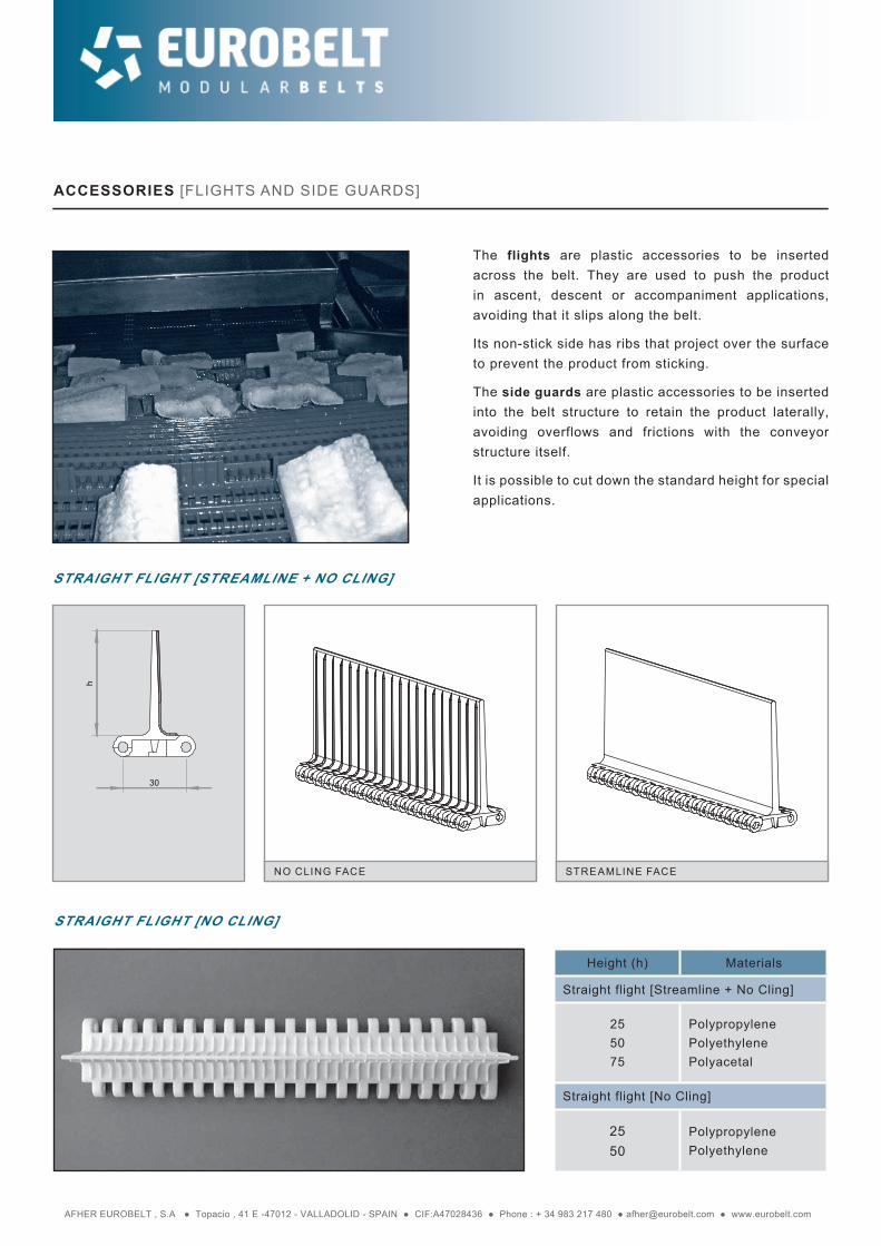
ACCESSORIES [FLIGHTS AND SIDE GUARDS]
The flights are plastic accessories to be inserted across the belt. They are used to push the product in ascent, descent or accompaniment applications, avoiding that it slips along the belt.
Its non-stick side has ribs that project over the surface to prevent the product from sticking.
The side guards are plastic accessories to be inserted into the belt structure to retain the product laterally, avoiding overflows and frictions with the conveyor structure itself.
It is possible to cut down the standard height for special applications.
STRAIGHT FLIGHT [STREAMLINE + NO CLING]
NO CLING FACE STREAMLINE FACE
STRAIGHT FLIGHT [NO CLING]
Height (h) Materials
Straight flight [Streamline + No Cling]
255075
PolypropylenePolyethylenePolyacetal
Straight flight [No Cling]
2550
PolypropylenePolyethylene

AFHER EUROBELT , S.A ● Topacio , 41 E -47012 - VALLADOLID - SPAIN ● CIF:A47028436 ● Phone : + 34 983 217 480 ● [email protected] ● www.eurobelt.com
30
h
h
304.3
Sentidode marcha
Drivedirection
Sensde marche
Sentidode marcha
Sensde marche
Drivedirection
BENT FLIGHT
SIDE GUARDS
Accessories Height (h) Materials
Bent Flight[Streamline + No Cling]
4570
PolypropylenePolyethylenePolyacetal
Accessories Height (h) Materials
Side guards5075
PolypropylenePolyethylenePolyacetal
SERIES / E30

AFHER EUROBELT , S.A ● Topacio , 41 E -47012 - VALLADOLID - SPAIN ● CIF:A47028436 ● Phone : + 34 983 217 480 ● [email protected] ● www.eurobelt.com
Indent Indent
10 A 10A
∅15
Indent Indent
Indent Indent
10 10
Indent Indent
10 A 10A
∅15
Indent Indent
Indent Indent
10 10
Indent Indent
10 A 10A
∅15
Indent Indent
Indent Indent
10 10
L.C. L.C.
TECHNICAL DATA [FLIGHTS AND SIDE GUARDS]
E30 / SERIES
BELT ONLY WITH FLIGHTS
BELT ONLY WITH SIDE GUARDS BELT WITH FLIGHTS AND SIDE GUARDS
Indent = Multiples of 10 mm (30 mm the minimum)(1).
Distance between flights = Multiples of 60. Flight longitudinal cut = increment of 10 mm (minimum 30 mm)
Indent = Multiples of 10 mm (20 mm the minimum). A= 10 mm
Multiples of 10 + 5 mm (25 mm the minimum). A= 5 mm
Indent = Multiples of 10 mm (20 mm the minimum).
Multiples of 10 + 5 mm (25 mm the minimum).
BELT WITH ZIGZAG FLIGHTS
BELT WITH LONGITUDINAL CUTS
BELT WITH FLIGHTS, WITHOUT INDENT
(1) Ask for the possibility of shaping your belt with a smaller indent than that recommended.

AFHER EUROBELT , S.A ● Topacio , 41 E -47012 - VALLADOLID - SPAIN ● CIF:A47028436 ● Phone : + 34 983 217 480 ● [email protected] ● www.eurobelt.com
ELEVATING CONVEYOR WITH FLIGHTS
CONSTRUCTION DATA [CONVEYOR]
HORIZONTAL CONVEYOR
In the construction of conveyors, the distances appearing in the chart below must be respected according to the belt Series and the size of the sprockets.
A
200 ÷ 300
A
B
B
R min. 150
R min. 150
RollerØ mín. 75
R min. 150
200 ÷ 300
D
Wearstrips
C max.
Belt widthWearstrips
Flight support if belt width ≥ 600
C max.
Belt width
C Max.
B B
200 ÷ 300>400
A
[A] Distance between the sliding surface of the belt and the centre of the shaft.
[B] Distance between the vertical of the shaft and the beginning of the sliding surface.
[C] Distance between the sliding surface of the belt and the support of the return way.
[D] If sprockets are used in the inflexion shaft, do not retain the central one.
[R] This radius must be as big as allowed by the application in order to minimize the wear (min. 150 mm). For belts with side guards, consult about this radius.
E30 / SERIES
Nº of teeth T
ØPitch
AB
max.C
max.
6 60 25 30 65
9 87.7 37 40 92
11 106.5 48 50 110
14 134,8 62 43 135
16 153.5 73 65 155
20 191.5 91 75 195

AFHER EUROBELT , S.A ● Topacio , 41 E -47012 - VALLADOLID - SPAIN ● CIF:A47028436 ● Phone : + 34 983 217 480 ● [email protected] ● www.eurobelt.com
SERIES / E30
TABLE OF SPROCKETS AND WEARSTRIPS
Belt nominalwidth (mm)
Minimum quantityof sprockets per shaft
Minimum quantityof wearstrips
Transport way Return way
40 100 1 2 2
110 300 3 2 2
310 500 5 4 3
510 700 7 6 4
710 900 9 8 5
910 1,100 11 10 6
1,110 1,300 13 12 7
1,310 1,500 15 14 8
1,510 1,700 17 16 9
1,710 1,900 19 18 11
1,910 2,100 21 20 12
2,110 2,300 23 22 13
2,310 2,500 25 24 14
2,510 2,700 27 26 15
2,710 2,900 29 28 16
2,910 3,100 31 30 17
3,110 3,300 33 32 18
3,310 3,500 35 34 19
3,510 3,700 37 36 21
To calculate the necessary minimum quantity of sprockets for the drive shaft as well as for the idle one, the next formula has been used:
This amount must always be odd.
To calculate the quantity of supports, the weight of the product to be transported must be taken into account.
The distance between supports should not exceed 150 mm in the transport way or 300 mm in the return way.
Minimum quantity =Belt width (mm)
100 mm

AFHER EUROBELT , S.A ● Topacio , 41 E -47012 - VALLADOLID - SPAIN ● CIF:A47028436 ● Phone : + 34 983 217 480 ● [email protected] ● www.eurobelt.com
13
20
20
12
3814
61830
20
12
6 6
37
40
35
6 500
32
13
20
20
123
814
61830
20
12
6 6
37
40
35
6 500
32
PROFILES IN L
PROFILES IN U
ACCESSORIES [HOLD-DOWN PROFILES]
To make the fastening and the support of the belt, EUROBELT has designed two types of hold-down profiles with different geometries, but with the same uses and services.
These profiles, with a low coefficient of friction, are placed between the belt and the structure of the conveyor, reducing the wear of the surfaces in contact, which contributes to prolong the life of the belt.
EUROBELT offers all the hold-down profiles in special polyethylenes with very good sliding properties and an excellent resistance to impact.
Accessories Dimensions Materials
Profiles in L40 x 20 x 2.000
Polyethylene35 x 12 x 2.000
Profiles in U20 x 30 x 2.000
20 x 14 x 2.000
ACCESSORIES

AFHER EUROBELT , S.A ● Topacio , 41 E -47012 - VALLADOLID - SPAIN ● CIF:A47028436 ● Phone : + 34 983 217 480 ● [email protected] ● www.eurobelt.com
Ø12.5
Ø 6.5
500
6
32
40
"A"
"B"
20
PARALLEL RUNNERS CHEVRON ARRAY
It consists of placing the wearstrips in a parallel and continuous way along the conveyor structure.
It is preferable to position them so that the joints do not coincide.
This is probably the simplest and most economical configuration although, depending on the load to be transported, uneven wears can arise on the back surface of the belt.
It is not advisable for applications with a very heavy load.
The wearstrips are placed throughout the length and breadth of the conveyor, as shown in the picture above.
The possible wear that might occur will be even all over the belt, since it is resting on the wearstrips lengthwise and breadthwise.
With this angle-shaped layout the cleaning and the removal of wastes are easy.
It is advisable for applications bearing heavy loads or for high speeds.
ACCESSORIES [WEARSTRIPS]
The flat wearstrips are fastened by means of flatheaded plastic screws, which contributes to obtain a smooth surface free of any possibility of hooking.
The dimensions of those screws are: M 6 x 25 mm.
Due to their dovetail design, they can adapt to possible longitudinal contractions and expansions of the belt.
Dimensions Materials
6 x 32 x 500PolyethyleneConductive polyethylenePolyacetal
The wearstrips arrangement is an important factor in the life span of a conveyor belt. It should be chosen the most suitable configuration according to the transport needs. To calculate the quantity of supports, the weight of the product to be conveyed should be taken into account.
ACCESSORIES


![SERIES / C12 - Eurobelt · 2020. 9. 2. · C12 / SERIES ACCESSORIES [SPROCKETS] Bore Nº of teeth T Pitch diameter Bore for square shaft Hub width Material mm inch 11 42.59 20 ¾”](https://img.dokumen.tips/doc/110x75/61343ebedfd10f4dd73b9b6d/series-c12-eurobelt-2020-9-2-c12-series-accessories-sprockets-bore.jpg)